1. Introduction
Extensive mandibular defects resulting from malignant tumor resection require the reconstruction of mandibular continuity, taking into account both function and aesthetics [
1,
2]. In most cases, the osteocutaneous fibular free flap is the first choice because it offers several advantages such as a reliable vascular pedicle, flexibility, sufficient bone quality and length, and the possibility of a two-team approach [
1,
3]. However, when the neomandible is created using a single layer of fibula bone, the height is usually insufficient compared to the actual mandible, requiring the surgeon to position the segments in a compromised manner while considering aesthetics and function [
4]. To overcome this limitation, the proposed double-barrel fibula flap method involves reconstructing the fibular segments by folding the bone into two layers [
5,
6]. The upper layer can be used to restore function by installing osseointegrated dental implants at a later stage, whereas the lower layer is positioned in accordance with the mandibular border to achieve optimal aesthetics. However, compared to the single-layer surgery, this double-barreling technique is more challenging and requires greater skill to handle and position the bones and pedicle without the de-vascularization of the flap [
7,
8]. Therefore, the operation time may be longer, and the risks may be higher [
7].
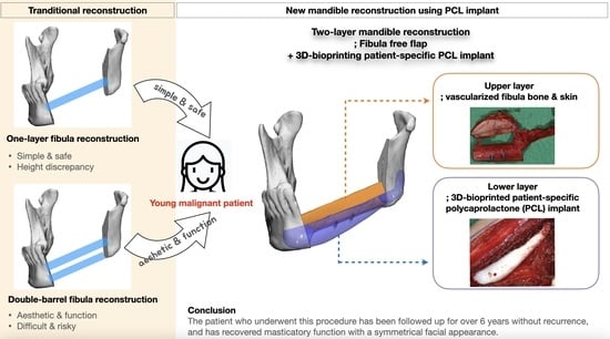
The purpose of this paper is to propose a novel surgical option that combines a microvascular fibula free flap with a patient-specific, 3D-bioprinted PCL implant to achieve a simple two-layer reconstruction while eliminating the technical difficulties in double-barreling. To the best of our knowledge, this is the first long term follow-up case to combine an osteocutaneous fibula free flap and 3D-bioprinted PCL implant in mandible reconstruction.
2. Methods
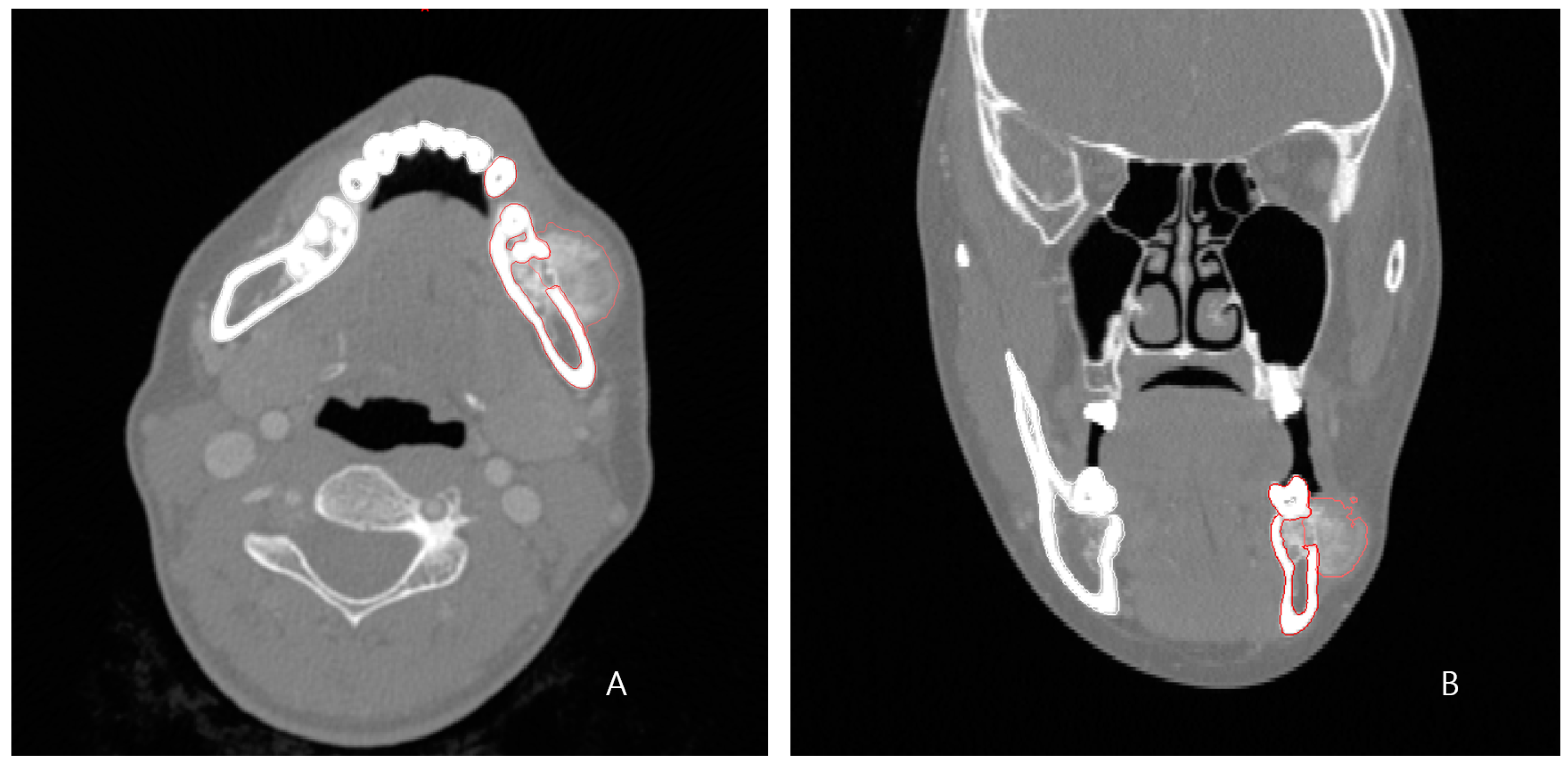
A 24-year-old female patient was identified with osteosarcoma of the left mandible body and referred to Kyung Hee University Dental Hospital. Preoperative enhanced computed tomography (CT) and enhanced magnetic resonance imaging (MRI) confirmed a tumor of approximately 2.5 cm that had eroded the buccal cortical bone and was bulging out (
Figure 1). A wide excision, including segmental mandibulectomy, was planned with a sufficient safety margin. The fibula free flap was considered first since a bony free flap containing soft tissue was required to repair the lining oral mucosa and mandible.
Our patient was a young female, and a more complete reconstruction result was desired without compromising both function and aesthetics, unlike in the case of an elderly patient suffering from a malignant lesion. Additionally, as the tumor was malignant, not benign, a simple and rapid reconstruction operation was necessary to minimize the risk and complications in consideration of the possibility of subsequent treatment. Therefore, considering all of the above, we devised a design that combined the fibular segment and the bio-printed PCL scaffold in two layers instead of the double-barrel method. The fibular portion was placed at the alveolus level for load-bearing and subsequent dental implant insertion, and the PCL scaffold was positioned beneath it to reproduce the patient’s original mandible border contour. This idea was made possible by computer-assisted design/computer-assisted manufacturing (CAD/CAM) and 3D printing technology.
2.1. Computer-Assisted Surgical Planning and Design of Patient-Specific Implant
The preoperative patient’s craniomaxillofacial skeleton and lower extremities region-enhanced CT images with slice thicknesses of 1.0 mm were stored in the digital imaging and communication in medical (DICOM) format. These datasets were imported into medical simulation software (Mimics, Materialize NV, Leuven, Belgium) to generate the skull and fibula models through segmentation processing. The standard tessellation language (STL) files of these 3D objects were transferred to medical CAD software (3-matic
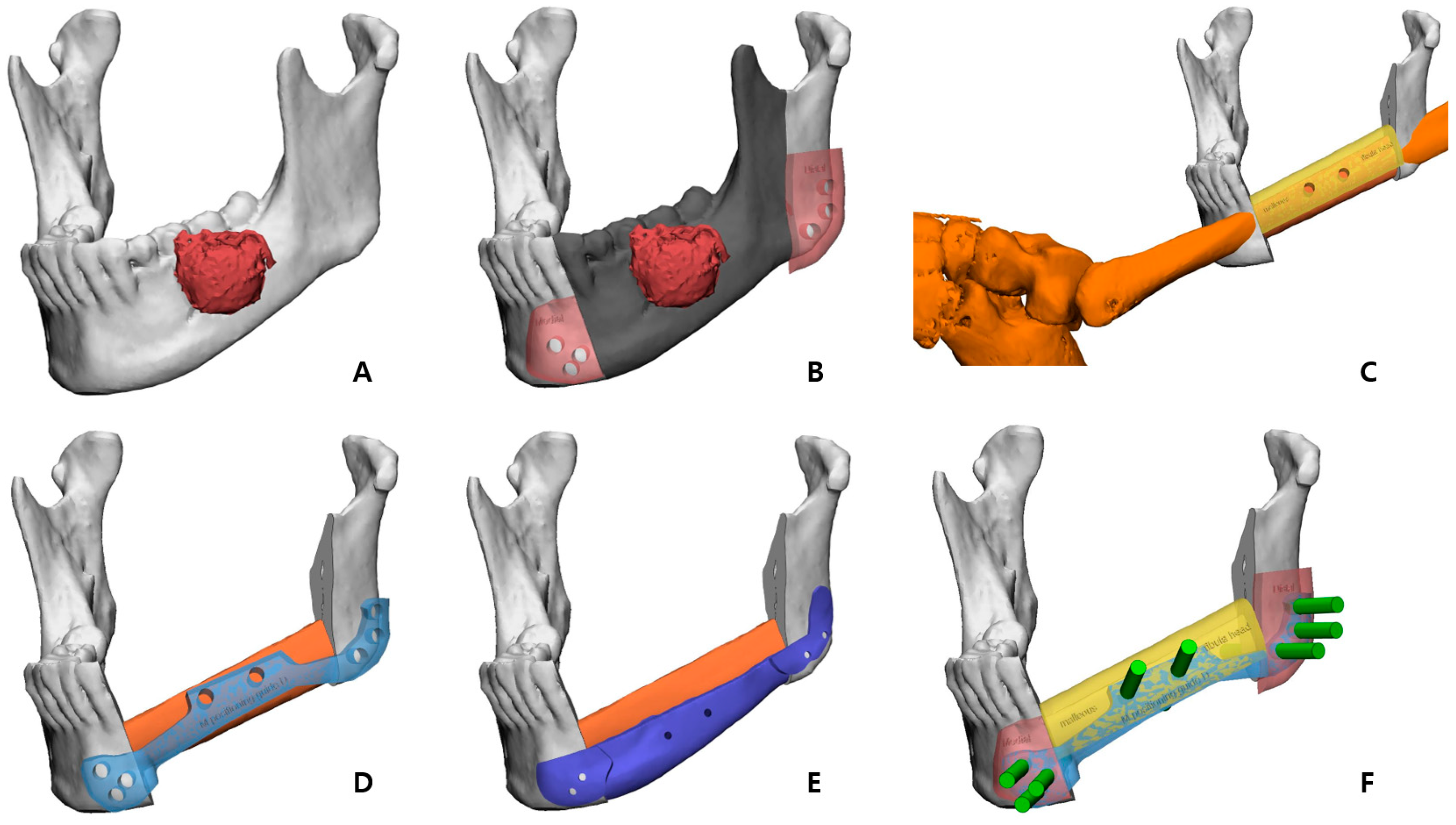
®, Materialize NV, Leuven, Belgium). The mass was extracted by overlapping the enhanced MRI data with the CT data (
Figure 2A), and, based on this, the resection part, including the first premolar to the mandibular notch, was determined with a proper safety margin.
After performing the planned mandibulectomy on the software, mandible cutting guides were designed to implement it (
Figure 2B). The left fibula model was moved to the resection area, and the fibula model was positioned at the alveolar level to facilitate later implant placement, considering the fibula’s shape and pedicle location. To achieve this, the fibula cutting guide and the fibula positioning guide were created (
Figure 2C,D). In the inferior part, the scaffold that reproduced the original shape of the patient’s mandibular border was designed to partially cover the outer and lower side of the fibular segment to recreate the volume, and, at the same time, it was intended to support the position of the fibula more accurately (
Figure 3). Wing-shaped connection parts with fixation holes that could be fixed to the remaining mandible were added on both sides of the scaffold (
Figure 2E). All surgical guides and the scaffold were designed to be fixed with screws through fixation holes, and the locations of these fixation holes were shared to enable reconstruction (
Figure 2F).
2.2. Fabrication of Surgical Guides and 3D-Bioprinted PCL Implant
The STL file of the PCL implant was sent to a bioprinting company (T&R Biofab Co. Ltd., Seoul, Republic of Korea), which produced it using medical-grade PCL (Evonik Industries, Essen, Germany) in Biofab’s 3D printing system. The PCL raw material was placed within a 10 mL steel syringe for printing. The PCL was heated to 120 °C, which was maintained for the printing duration. The molten PCL was then extruded through 500 µm steel nozzles. The printing code was generated by CAM software. The code was served to slice the customized 3D models and generated a moving path for the 3D printer to operate. The PCL scaffold was then fabricated with interconnected lattice-type pores (
Figure 3E). This entire process was performed in accordance with a facility with Good Manufacturing Practice (GMP) certification approved by the MFDS of Korea, and the final fabricated implant was prepared by gamma sterilization.
The surgical guides that we designed were directly printed using our own 3D printer (Form2, Formlabs, Somerville, MA, USA) with clear resin (Formlabs, Somerville, MA, USA), and these were sterilized by the hospital system.
2.3. Surgical Technique
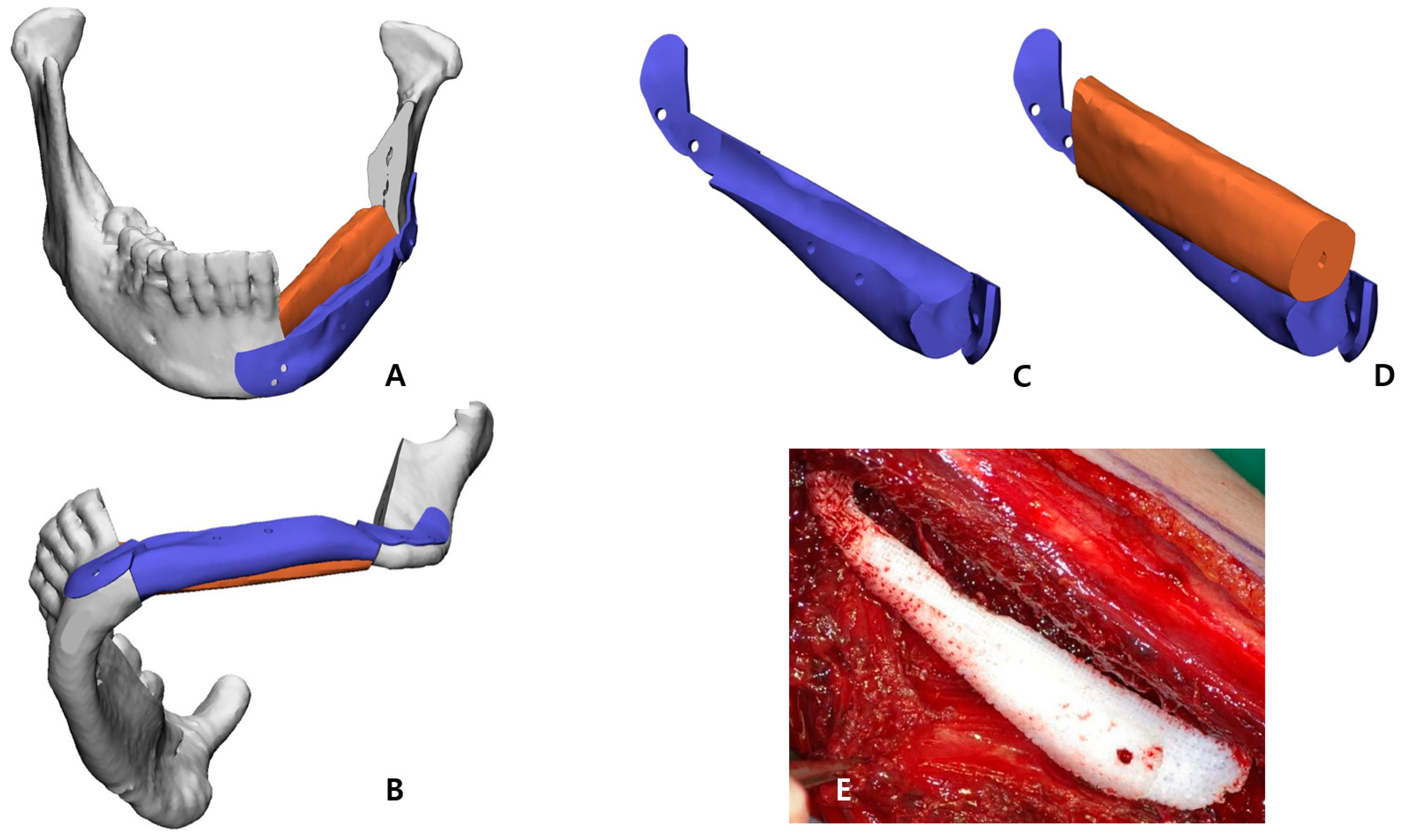
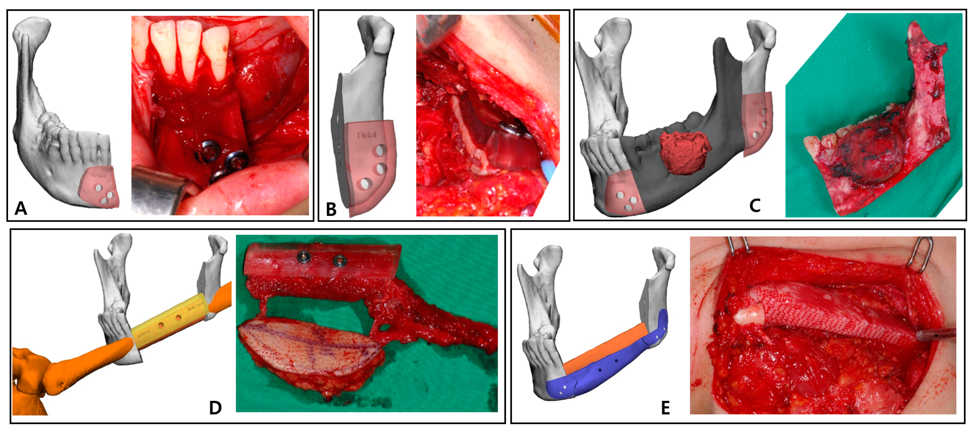
The left mandible and tumor were minimally exposed through simultaneous access to the neck and oral cavity without lip splitting. The transparent mandible cutting guides were adapted to the intended location, drilled in accordance with the fixing holes, and secured with screws (
Figure 4A,B). The holes generated in the residual mandible were also planned to be used to attach the PCL implant and the fibula positioning guide in the subsequent process. The osteotomy was completed according to the mandible cutting guides, and the mandibular fragment containing the mass was removed in one-bloc (
Figure 4C).
The osteofasciocutaneous fibula free flap with a fusiform skin paddle was obtained from the left lower leg by conventional lateral access. Before separating the vascular pedicle, the fibula cutting guide was precisely positioned on the outer surface of the fibula, drilled along the fixation holes, and monocortically fastened with screws. Then, piezoelectric osteotomy was elaborately implemented according to this fibula cutting guide, and the fibula free flap was harvested (
Figure 4D). Immediately after this stage, the bio-printed PCL implant was briefly placed in the extracted fibular space to soak in blood containing bone marrow (
Figure 3E).
After placing the fibula segment on the defect of the mandible, the fibula positioning guide was accurately fixed with screws using holes already formed in the remaining mandible and fibula segment. In this state, the fibula segment and the remnant mandible were connected with mini-plates and mini-screws. The positioning guide was eliminated, and the patient-specific PCL implant was arranged below the fibula segment (
Figure 4E). This scaffold was also fixed with screws using existing holes of the residual mandible. After microvascular anastomosis in the left neck area, the skin paddle regenerated an oral mucosa, and the neck region was closed.
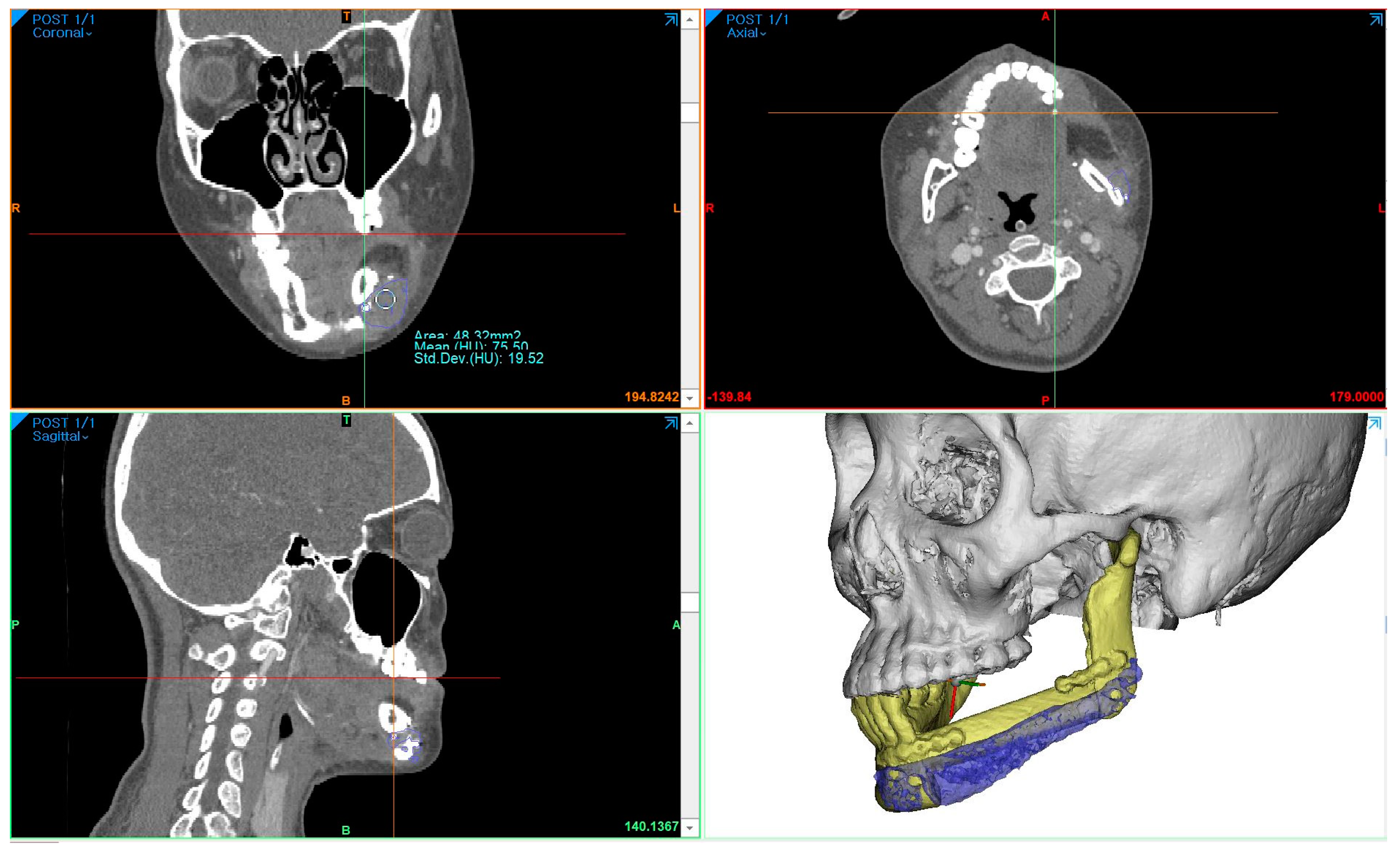
2.4. Density and Accuracy Analysis Based on CT Data
To measure the density of the PCL implant using follow-up-enhanced CT and Mimics software, the same location where the PCL was positioned at the level of the maxillary first molar was identified in the coronal view. At this specific location, the mean value and standard deviation of the Hounsfield units (HUs) were obtained using the “density” function (
Figure 5). To compare accuracy on the same software, 3D models of surgical planning and the 3D model generated from the CT data taken two weeks after the operation were superimposed, and the error was calculated through mapping analysis.
3. Results
The patient was discharged without any complications after surgery, and the histopathological findings showed chondroblastic osteosarcoma, grade IV, with tumor-free margins. She underwent adjuvant chemotherapy with six cycles of high-dose methotrexate postoperatively and was followed up for over 6 years without metastasis, recurrence, or complications.
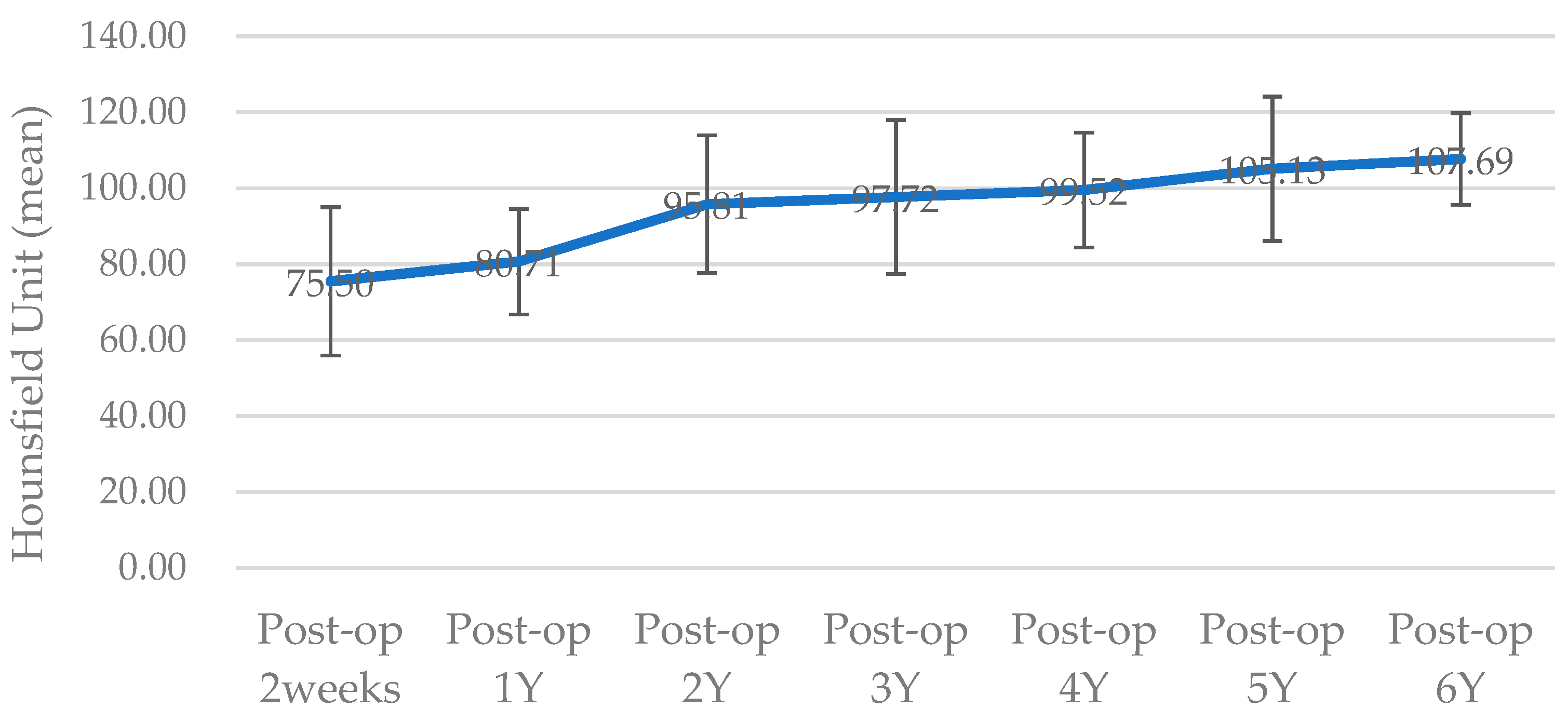
The surgical results were analyzed using enhanced CT and MRI, which were radiographic images taken for the purpose of tracking malignant tumors. Follow-up CT scans were conducted at 2 weeks postoperatively and every year for the next 6 years, whereas MRI scans were performed only at 5 months, 11 months, 40 months, and 4-and-a-half years after surgery. The PCL implant exhibited similar attenuation to the surrounding soft tissue on the enhanced CT images, making it challenging to accurately generate a 3D model rendering in the Mimics software. The Hounsfield unit value of the PCL implant was measured using the “density” function in this software. It was observed that the density progressively increased over the years, from 75.50 at 2 weeks after surgery to 107.69 at 6 years after surgery (
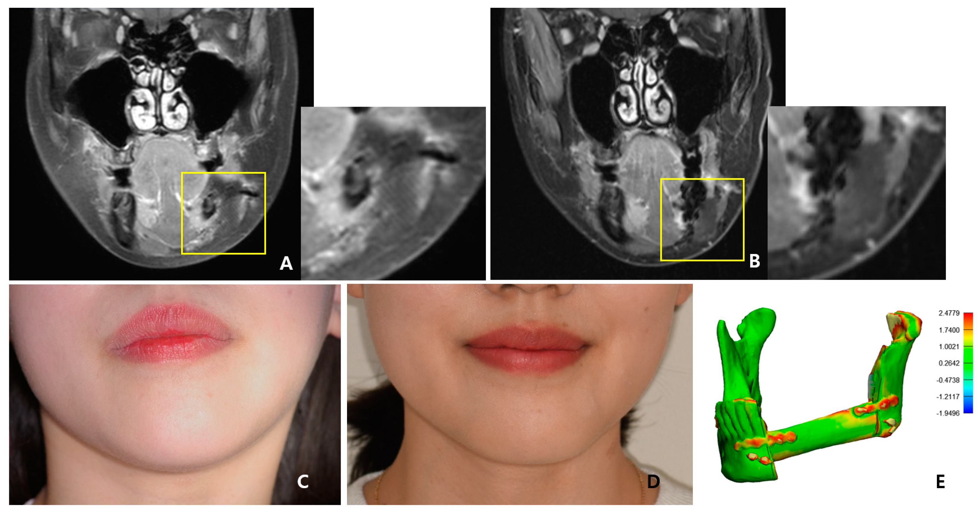
Figure 6). All average values were within the range of muscle thresholds. On the follow-up MRI, the PCL implant exhibited signals between the surrounding soft tissue and hard tissue, allowing for clear margin distinction. Consequently, changes in volume could be observed on the MRI, and there were no significant changes until 4-and-a-half years after surgery. The lattice pattern of the PCL, which was clearly observed until the 11-month postoperative MRI image, was absent in the 40-month postoperative MRI image, and it was analyzed that only the surface of the PCL had been replaced with soft tissue (
Figure 7A,B). By superimposing the model immediately after surgery with the virtual plan, it was determined that the error was within 1 mm, except for the condylar head (
Figure 7E).
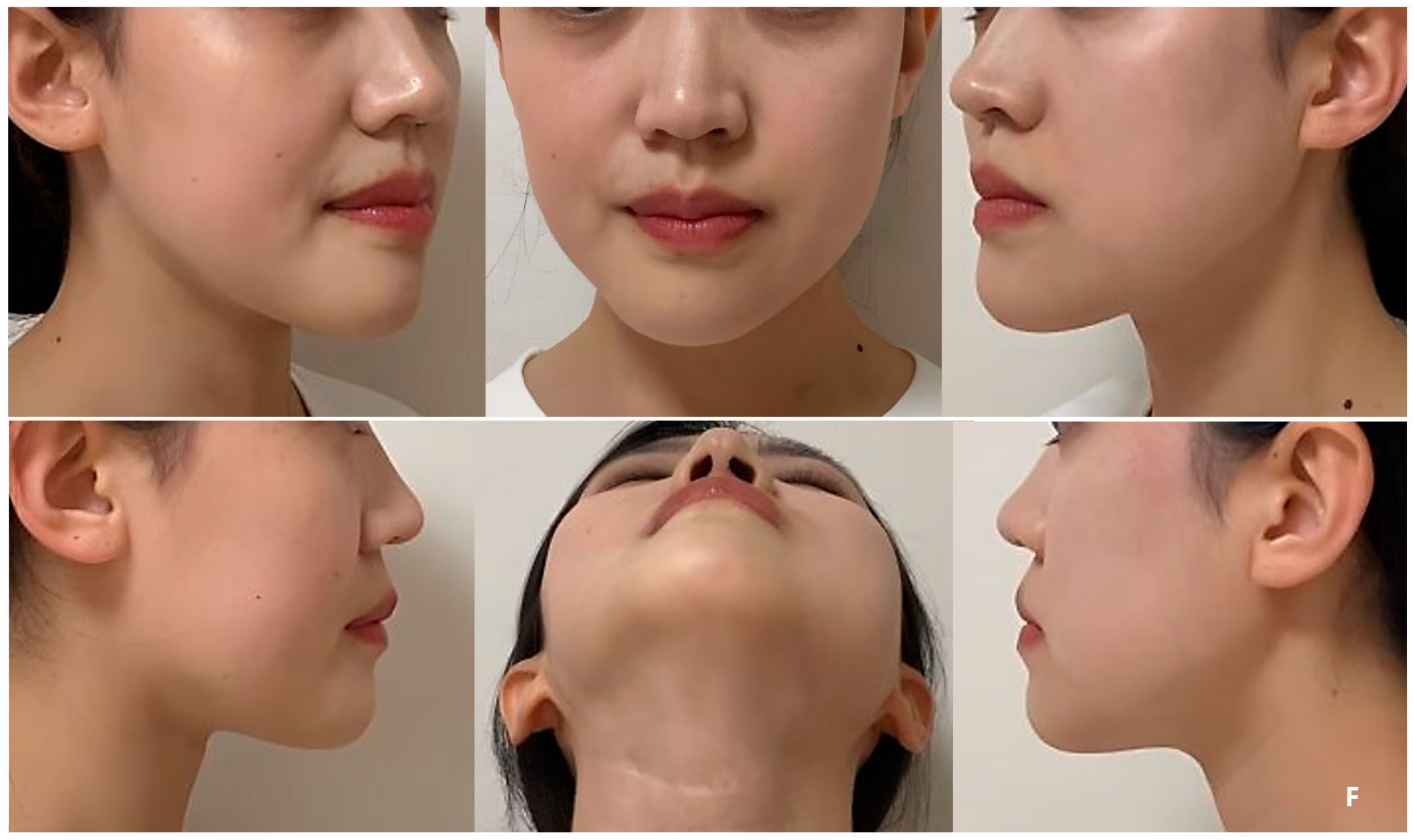
As shown in the series of facial clinical photos, the patient’s surgical site has been maintaining volume symmetry without any deformation for over 6 years, and the patient has been satisfied with her appearance (
Figure 7C,D,F). During each follow-up, upon palpation of the reconstructed region, it was confirmed that the PCL implant area was firmly maintained and smoothly connected to the mandible without any irregular edges.
Three years after cancer surgery, 2-stage dental implant (TS-III CA; Osstem Implant Co., Busan, Republic of Korea) installation was performed outpatiently under local anesthesia, the final implant prosthesis was completed 4 years after surgery, and the patient recovered functionally and aesthetically (
Figure 8).
4. Discussion
The purpose of this paper was to propose a surgical option that combined a microvascular fibula free flap with a patient-specific PCL implant as a safe and simple novel method that achieved the best results both functionally and aesthetically in mandible reconstruction surgery for young patients with malignant tumors.
As the fibula free flap became the gold standard in mandibular reconstruction that required soft tissue and hard tissue simultaneously, various methods have been sought to solve the height discrepancy between the mandible and fibula, which was almost the only limitation [
4,
9]. These included the double-barrel fibula, the use of an additional inferior reconstruction plate, and vertical distraction osteogenesis [
4,
5,
10,
11]. After Horiuchi et al. proposed the double-barrel fibula graft for mandibular reconstruction in 1995, several successful results of the method have been published [
6]. In particular, with the recent development of 3D simulation CAD/CAM and 3D printing technology, more diverse attempts have become possible [
3,
12,
13]. Yang et al. produced a design that increased the accuracy in the positioning of two-strut fibula segments by fabricating a “one-piece” patient-specific plate [
14]. Berrone et al. used long dental implants to secure the double-barrel segments and fixed only the lower layer to the mandible using a patient-specific plate [
15]. Lee et al. reproduced the planned position through virtual surgery by fixing the double-barrel fibula with the positioning guide that shared screw holes and then performed fixation using a mini-plate in that state to ensure accuracy [
16]. Although the problem of difficulty in precisely locating multiple bone segments as mentioned above could be overcome with technology, the double-barrel fibula graft was still complicated and risky due to the fundamental limitation of folding the pedicle [
7].
In order to overcome the restriction of the double-barrel fibula graft and enable two-strut reconstruction [
17], Lee et al. proposed a hybrid graft method with a non-vascularized residual fibula bone [
7]. Since then, various designs have been tried that placed non-vascularized fibula segments only in areas necessary for dental implant placement. Although these options simplified the operation, there were cases where the non-vascular part was resorbed, and bone formation was not possible [
18]. Therefore, to prevent the possibility of resorption of the site where dental implants were to be inserted, we placed the vascular fibula segment at the alveolar level so that the autogenous bone continued and located the patient-specific PCL implant below that reproduced the original shape of the mandible. This surgical option for two-layer reconstruction was simple, safe, and provided an ideal outcome.
Polycaprolactone (PCL) is an FDA-approved, biocompatible, and biodegradable safety biomaterial that has been studied as a drug delivery device since the 1970s [
19,
20]. Recently, it has been used not only to prevent airway stenosis in infants with tracheobronchomalacia but also to be applied for the reconstruction of maxillary, infraorbital, and cranial defects as a patient-specific, 3D-printed scaffold [
21,
22,
23]. According to the finite element analysis of mandible reconstruction, PCL alone cannot withstand the masticatory force, and the wing design helps to distribute the stress [
24,
25]. Our design also did not use PCL alone; we placed it in the lower part, unrelated to the bearing of the masticatory force, and added the wing design to disperse stress. This wing part shared the holes with the drilling holes of surgical guides so that the PCL implant could be secured in the planned position. Additionally, the PCL implant was designed to cover the inferior surface of the fibula bone, which had the benefit of guiding the location of the fibula part.
Han et al. applied a patient-specific PCL scaffold to reconstruct a complex maxillary defect and reported stable and aesthetic surgical results [
21]. The Hounsfield unit values of CT images at 6 months and 16 months after surgery were compared and analyzed as an increase in scaffold density. However, even on enhanced CT, the PCL part was distinguishable from the hard tissue but had a similar attenuation to the surrounding soft tissues. As a result, it was impossible to clearly demarcate the margin of the PCL, and only the extent of its position could be grasped. Therefore, in order to objectively compare the density of the PCL, HUs measured at the same location were required. In our case, the maxillary tooth and surrounding hemoclip in a fixed position were used as references. The HU values were acquired using the “density” function of the Mimics software. These values increased gradually each year, with all falling within the range of HU values for muscle. This observation suggested that the biodegradable PCL was replaced by soft tissues with a density similar to that of muscle, leading to an overall increase in density. Jeong et al. reported accurate and esthetic surgical outcomes of eight patients in zygomatico-maxillary reconstruction using a PCL/beta tricalcium phosphate (β-TCP) scaffold [
22]. In their analysis of the results based on CT, a volume-rendering 3D model was created for the postsurgical implant to calculate the volume increase, and the HU values were measured to report the rate of new bone formation. However, due to the similar attenuation of the PCL implant to the nearby soft tissue, it was not possible to generate a volume-rendering model of the PCL implant alone in CT through segmentation. In contrast, on the MRI, the PCL implant showed intermediated signals between the hard tissue and the soft tissue; thus, it was possible to establish the boundary between the surrounding soft tissues. Even the PCL implant with interconnected lattice-type pores was observed as a lattice pattern on the MRI image. This grid pattern, which was clearly seen on MRI at 5 and 11 months after surgery, was not observed from MRI at 40 months postoperatively. Therefore, volume comparison of the PCL was possible with MRI, not CT. When comparing the latest follow-up MRI images taken 4-and-a-half years postoperatively, with previous MRI images, it was observed that the volume of the patient’s PCL implant itself did not change significantly. This finding was in contrast to reports of active disassembly occurring at 2 to 3 years in general conditions [
19,
20,
26]. Additionally, it was seen that the surface of the PCL implant was replaced with soft tissue, having a signal similar to that of the muscle. Based on the fact that PCL is a biodegradable material, the above results could be interpreted as not regenerating into bone tissue at the resolved site but being replaced by the rigid soft tissue homogeneous to the muscle, so that the patient’s facial deformation may not occur.
Three-dimensional, metal-printed, patient-specific implants (PSIs) have been attempted as replacements for bone flaps in mandible reconstruction, and titanium (Ti) is preferred mainly due to its advantages such as its high tensile strength and osseointegration properties [
27,
28,
29]. Oassemar et al. reported that the application of titanium PSIs in mandible reconstruction is an alternative method, especially when the patient has poor general condition, previous surgery at the same site, radiation treatment, or a donor site vascular defect; thus, microsurgery is not possible [
30]. In addition, several cases of applying Ti PSIs to correct the asymmetry of the mandible have been reported [
29,
31,
32]. However, titanium facial implants continue to have problems such as extrusion, migration, foreign body reaction, and infection that alloplastic implants can have [
32,
33]. In particular, if dental implants are connected for masticatory function, they become more vulnerable to infection [
33]. Due to the enormous production cost and long production period, the patient’s economic burden is high, and there is a time limit in applying it to malignant patients; thus, there is still a limit to general use. In contrast, biodegradable PCL can overcome the restrictions of exposure, inflammation, and infection that metal implants have, and is less burdensome with a relatively shorter manufacturing period and lower cost than them [
19]. In order for PCL, which has these advantages, to be applied as a substitute for bone flaps in mandible reconstruction, bone generation must be possible, and additional research on this is needed [
21]. Additionally, for a clinical analysis, it seems necessary to have an attenuation that distinguishes PCL on CT images.
CAD/CAM and 3D printing technology ensure the accuracy of reconstruction, reduce operation time and ischemia time, and, eventually, improve surgical results [
3,
13,
15,
34]. Tack et al. reported in a literature review of 3D printing that it is applied in multiple surgical domains because of the above benefits, and there are many related papers in the order of surgical guides, surgical planning, and custom implants [
12]. Our surgical design utilizes all of the above techniques, and, as a result, accurate and safe surgery can be performed. In addition, the long-term stable clinical results of this case for over 6 years lead to considering the primary application of the surgical option in mandibular reconstruction for young patients. These patients are a target group that requires satisfying aesthetics and functions to a relatively higher degree. The biocompatible PCL implant has no absolute contraindications, although it may not be feasible for patients who cannot undergo the fibula free flap procedure mentioned earlier [
30], which is rare among young patients. To expand its applicability beyond young patients, it is necessary to reduce production time and cost. As the patient is tumor-free and has completed the 5-year follow-up period for malignant tumors, MRI and CT scans are not required. However, follow-ups of the reconstructed sites and dental implants will continue, allowing for data reporting over a longer period of time.


