Article

An Experimental Investigation of Tsunami Bore Impact on Coastal Structures

1
Department of Civil Engineering, Faculty of Engineering, Niğde Ömer Halisdemir University, Niğde 51240, Turkey
2
Department of Mechanical Engineering, Faculty of Engineering, Niğde Ömer Halisdemir University, Niğde 51240, Turkey
*
Author to whom correspondence should be addressed.
Hydrology 2024, 11(9), 131; https://doi.org/10.3390/hydrology11090131
Submission received: 6 June 2024 / Revised: 6 August 2024 / Accepted: 22 August 2024 / Published: 23 August 2024
(This article belongs to the Special Issue Climate Change Effects on Coastal Management)

Abstract

:
This experimental study focused on the measurement and analysis of the impact force caused by a tsunami bore on a coastal structure. The bore wave was produced by a dam break mechanism. The water depth in the reservoir and the location of the coastal structures were varied to simulate different impact scenarios. The time history of the force resulting from the impact of the bore wave on the coastal structure was measured. The propagation of the bore wave along the flume was recorded and the video recordings were converted into digital data using an image-processing technique in order to determine the flow depth variations with time. The hydrostatic forces and the corresponding depth and time-averaged hydrodynamic forces as well as the maximum hydrodynamic forces were acquired for each scenario. The ratio of hydrodynamic to hydrostatic forces were obtained, and it was observed that the calculated averaged ratio was within the recommended design ratio. The results indicate that an increase in the reservoir level caused an increase in the magnitude and intensity of the impact forces, however, the relationship was non-linear. Moreover, it was found that the location of the structure did not play a significant role on the intensity of the impact forces.

1. Introduction

In recent years, climate change and its consequences have attracted increasing attention among researchers and engineers because it poses a fundamental threat to our species, livelihood, and structures including coastal structures. Climate change results in not only sea level rise, but also affects the flow processes and wave dynamics in coastal zones. Changes in wave power can cause the failure of coastal structures including piers, docks, bridges, and breakwaters [1]. Failure of the structure occurs when the waves or bore impact on the structure produce loads that exceed the bearing capacity of the structure.
Reports of the different failures of coastal structures or structures within the tsunami impacted areas in the past have revealed the negative impact of tsunami bore on structures. The 2004 Indian Ocean tsunami, 2010 Chile tsunami, and 2011 Japan tsunami were the most destructive tsunami bore disasters in the world, with devastating impacts on coastal structures. For example, the Japan tsunami of 2011 caused the major destruction of breakwaters and harbor structures [2]. Likewise, the seawall designed to protect the town of Kirikiri against tsunami hazards collapsed due to the scouring at its base. Additionally, the concrete-lined dyke for coastal protection in Kanahama was damaged, and a number of railway bridges failed [3]. In addition to all of these, many residential buildings close to coastal areas were partially or completely destroyed [4]. Nistor et al. [5] showed the relation between the inundation depth and degree of damage to reinforced concrete buildings and pointed out that inundation depths of more than 5 m can result in partial damage.
The tsunami generated impact force includes hydrostatic, hydrodynamic, buoyant, and debris forces. The propagation speed and height of the tsunami wave play a crucial role in the magnitude of these forces. Therefore, in tsunami-prone areas, the combination of these forces needs to be accurately evaluated and taken into account in the design of structures to minimize such damage. These forces are often disregarded in the design of coastal structures, particularly in the design of structures in inundation areas caused by tsunamis. This may be due to the low probability of the occurrence of large-scale tsunamis [5]. However, the tsunami wave characteristics that are of importance in evaluating the magnitude of the impact of tsunamis have been numerically, analytically, and experimentally studied. Some of the numerical studies include the study of tsunami force on superstructures offshore [6], tsunami force on coastal bridge decks [7], mitigating tsunami effects on buildings [8], the beach slope effects on hydrodynamic loading [9], and the effectiveness of vegetation-embankment hybrid structures [10]. Additionally, other numerical studies include those that examined the impact force [11,12], kinematics [13,14], and impact force and kinematics [15,16].
Some analytical studies include the work of Okada et al. [17], which integrated static and dynamic load together. They proposed that the force per unit length of a coastal wall be treated as an equivalent hydrostatic load and that the resultant force is calculated as nine times the hydrostatic force of the inundation depth when there is no wave break-up, and an equivalent force of approximately 11 times the hydrostatic force of the inundation depth when there is wave break-up. The U.S. Army Coastal Engineering Research Center [18] also proposed that the tsunami force on a coastal vertical wall was four and a half times the hydrostatic load, while the U.S. FEMA [19] proposed eleven times the hydrostatic force of the inundation depth, provided the vertical wall is greater than or equal to 2.2 of the inundation depth.
Experimental studies on the impact of tsunami bore on coastal structures include the works of Robertson et al. [20], who investigated the application of hydrodynamic loading by the leading edge of a bore to a non-linear analysis of a reinforced concrete building damaged during the 2011 Tohoku tsunami, and Mizutani and Imamura [21], who measured the wave forces of tsunamis acting on coastal protection structures to revise the existing wave force equations. Moreover, Linton et al. [22] examined the performance of wood-frame walls subjected to wave loading by considering the hydrodynamic conditions and structural response for a range of tsunami heights, and Rahman et al. [23] investigated the effectiveness of seawalls in reducing tsunami forces on onshore structures. Similarly, Arnason [24] also studied tsunami forces on coastal structures, Kihara et al. [25] investigated the pressure and flow characteristics on a vertical tide by taking into account the impact, reflection, and overflow, Santo and Robertson [26] measured the force exerted by the tsunami bore on vertical structural elements, Robertson et al. [27] measured the tsunami bore-induced force on structures, and Thusyanthan and Madabhushi [28] investigated the effect of tsunami bore on a typical coastal house. Furthermore, Huo et al. [29] studied the hydrodynamic characteristics of surge and bore impacts on vertical walls, Liu et al. [9] investigated the effects of slope on hydrodynamic loading during dam-break wave propagation over different inclined beds, and Rajaie et al. [30] researched the pore pressure variations around structures due to tsunami-like bores propagating over permeable surfaces. Maqtan et al. [31] studied the scour profile at the landward toe of vertical seawalls induced by tsunami bores, while Shafiei et al. [32] highlighted the importance of understanding the hydrodynamic forces. Hayatdavoodi et al. [1] highlighted the complexity of bore wave–coastal structure interactions, emphasizing the necessity of taking into account factors like wave breaking, air pockets, and variable bathymetry.
In experimental studies, tsunami bores have been generated through two different approaches: the breaking of a reservoir of water [1,33,34,35,36,37] or breaking of a wave [8,38]. The shock wave resulting from a dam break (Figure 1) resembles a tsunami bore [37,39,40,41,42]. The tsunami wave propagates toward the shoreline and steepens. The wave speed decreases near the shoreline with decreasing water depths, then becomes unstable and eventually breaks, resulting in a bore with a large mass flux that can be very destructive. This phenomenon is similar to a dam break shock wave [40,43,44]. In this study, the bore was generated by the breaking of a reservoir by using a dam-break mechanism [45,46].
Although some empirical and semi empirical equations have been developed based on experimental studies, there exist significant differences in their applications to compute load, particularly on onshore structures [36]. This requires further studies to provide more guidelines for a robust design, averting possible damage to structures prone to tsunami bore.
This comprehensive experimental study, examining the forces caused by tsunami bore acting on structures and covering variable flow conditions and structural locations, aims at providing a set of data for the further development of more practical empirical equations and the validation of numerical models. Furthermore, this study also aims to provide a ratio of hydrodynamic to hydrostatic forces for comparison with previously proposed ratios that have been used in practical coastal structural design applications.
To achieve these aims, hydrodynamics forces were obtained with the help of a six axis load cell. The wave height at the first impact, which produces the strongest hydrodynamic force, immediately upstream of the structure was determined by an image processing technique. This technique was used to digitize camera images of the experimental studies. With this technique, the required flow depth values were attained without interfering with the flow [46,47,48]. Hydrostatic forces as well as the depth-averaged and time-averaged hydrodynamic forces, along with the maximum hydrodynamics forces, were obtained. A comparison of the hydrostatic forces with the hydrodynamics forces was made to acquire the equivalent hydrostatic forces of the hydrodynamic forces.
The rest of this paper is organized as follows. The introduction section presents the background to the study, a review of literature, and identifies the research need and motivation for the study. A description of the experimental setup and instrumentation are given in Section 2. The results are then analyzed and discussed in Section 3. Finally, our conclusions are drawn and presented in Section 4.

2. Materials and Methods

In this section, the experimental setup and the measurement methods for the impact forces and the flow depths due to the bore wave propagations on the dry downstream bed are presented.

2.1. Experimental Studies

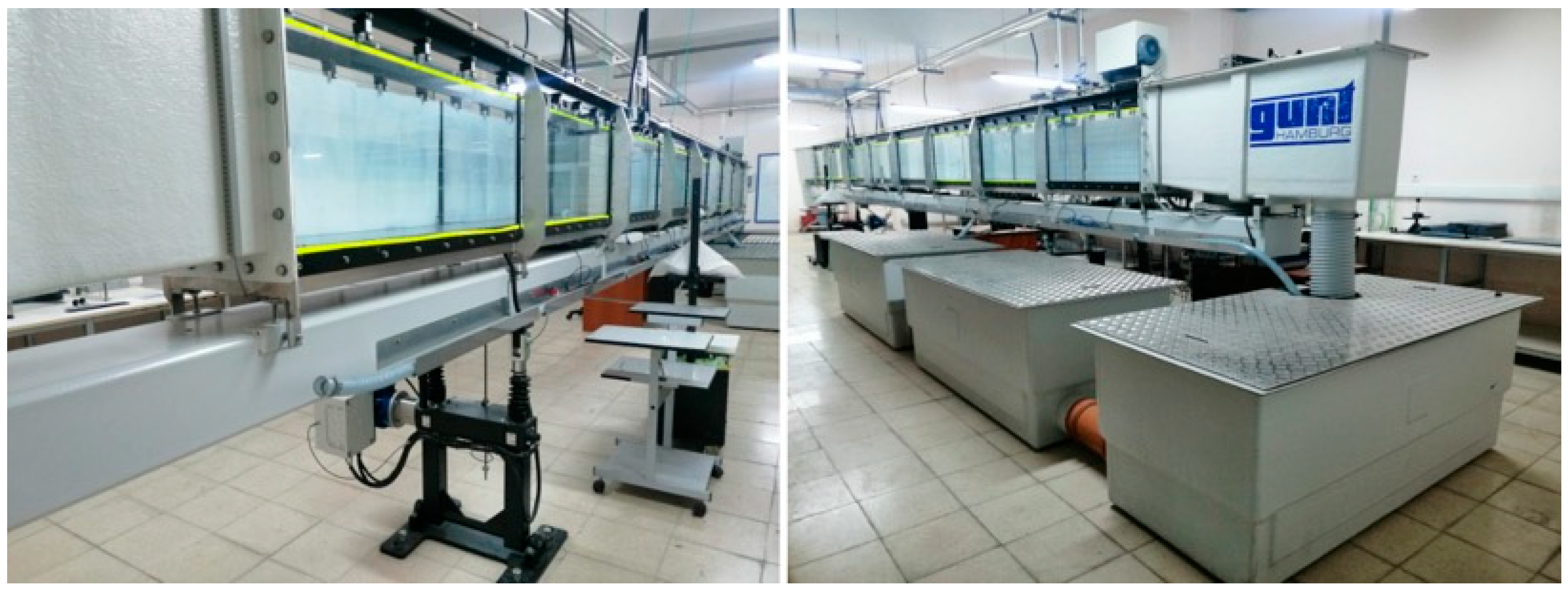
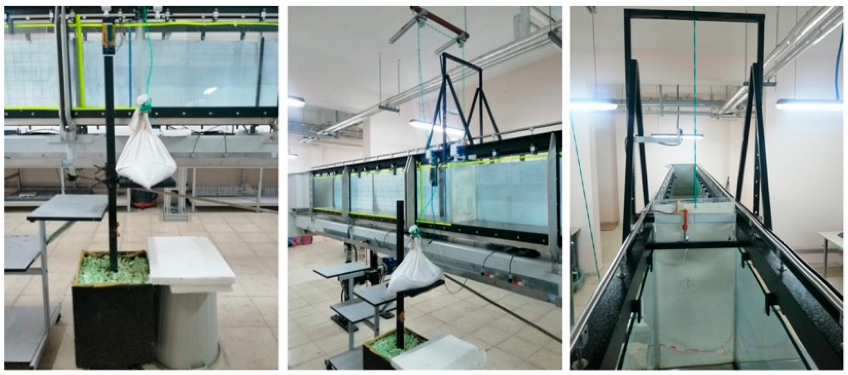
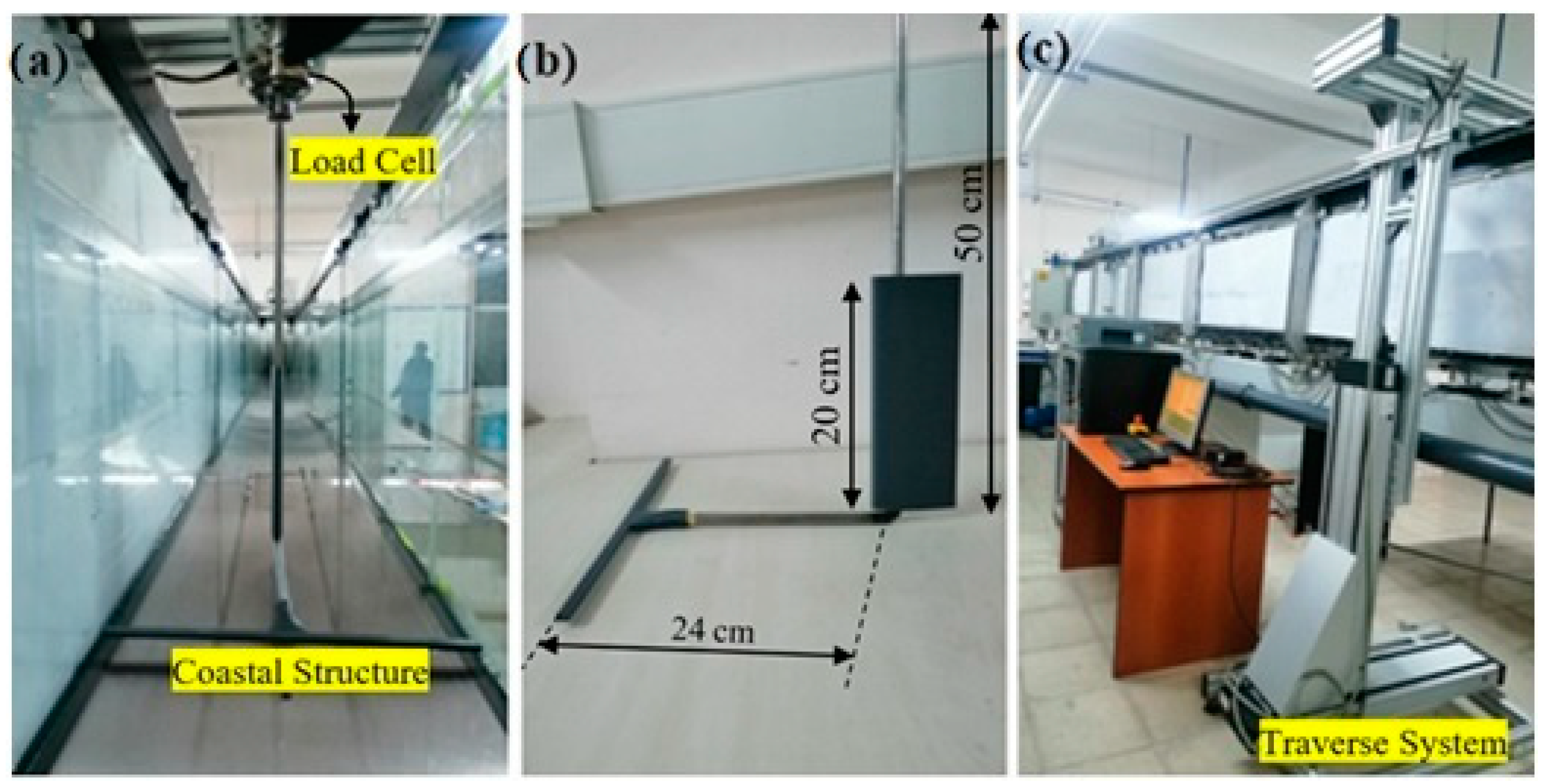
The experimental studies were carried out in a flume (HM162-GUNT) with dimensions of 10.0 × 0.309 × 0.5 m, located in the Hydraulics Laboratory of Niğde Ömer Halisdemir University, Faculty of Engineering, Department of Civil Engineering. The experimental flume was a rectangular cross-section flume with a horizontal flume bottom, a dry downstream bed, and an open outlet section (Figure 2). In the experiments, a gate representing the dam body was opened by freely dropping a 10 kg load connected to the pulley system from a height of 40 cm (Figure 3). In addition, a rectangular cross-sectional coastal structure with dimensions of 304 × 5 × 10 mm was designed and printed using a 3D printer. The hydrodynamic force acting on the structure was measured with the help of an ATI Mark GAMMA Model load cell for different reservoir water depths and different structure positions in the flume (Figure 4). A cell phone camera was also used to record the bore wave propagation, and video recordings were digitized to obtain the change in flow depth with time in front of the structure. These obtained records were then converted into numerical data with the image processing technique.
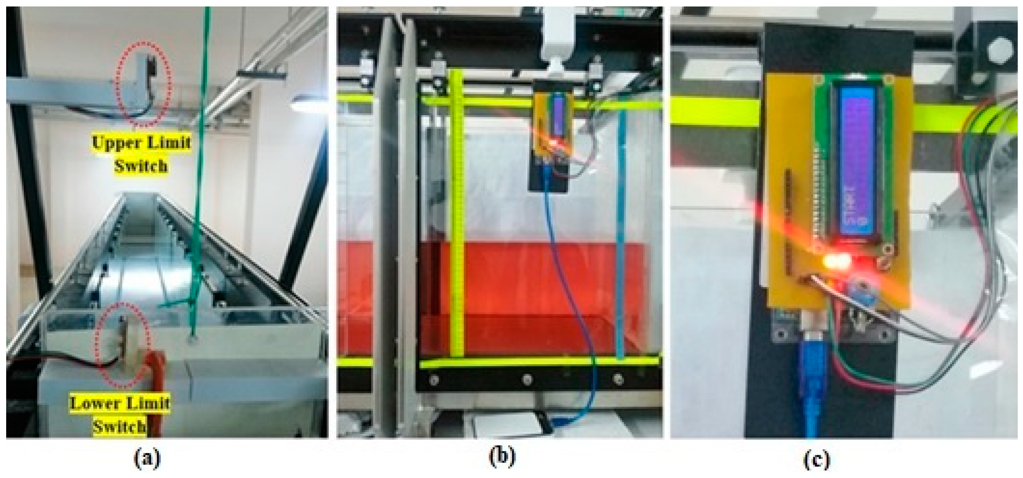
The experiments were carried out to satisfy the sudden gate opening criteria recommended by Lauber and Hager [49], and the gate opening time was measured with the Arduino system (Figure 5). In order to ensure approximately the same gate opening time for all experiments, a gate opening mechanism was built with a platform to hold the load. This platform was held in position with a hook; when the hook was opened, the load dropped from a fixed height in each experiment. Thus, almost the same gate opening time was recorded for each experiment. The measured gate opening times were 132 ms, 134 ms, 135 ms, and 143 ms for H10, H15, H20, and H25, respectively.
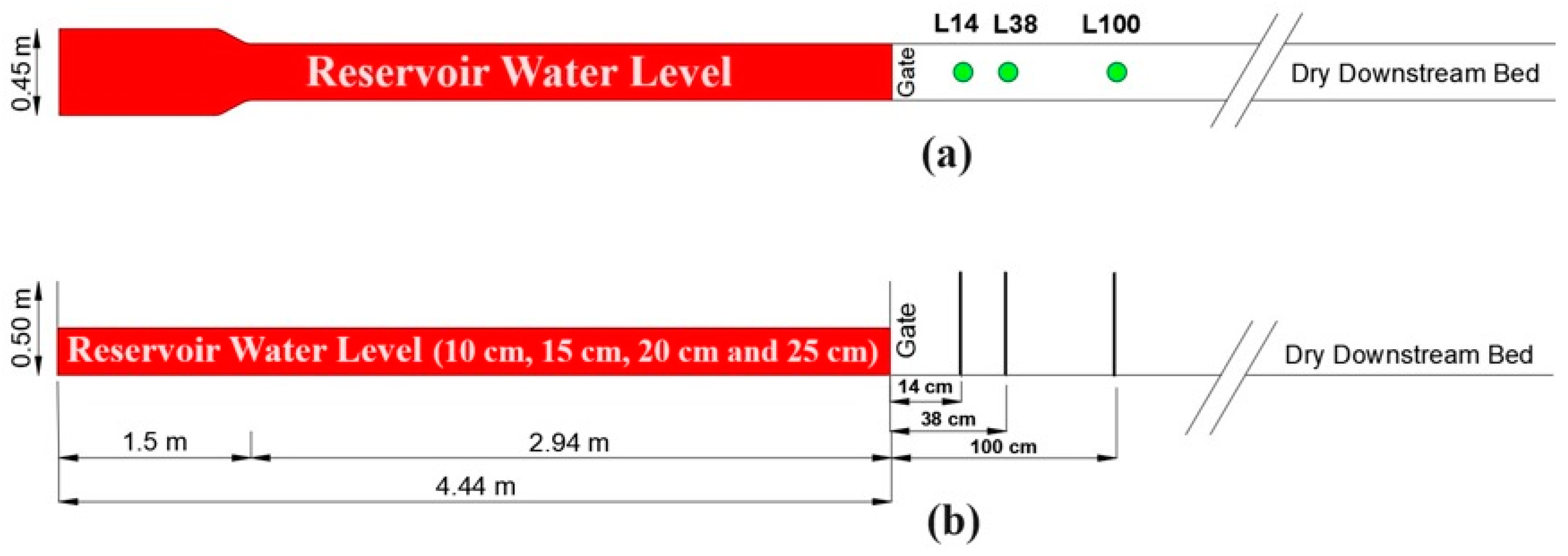
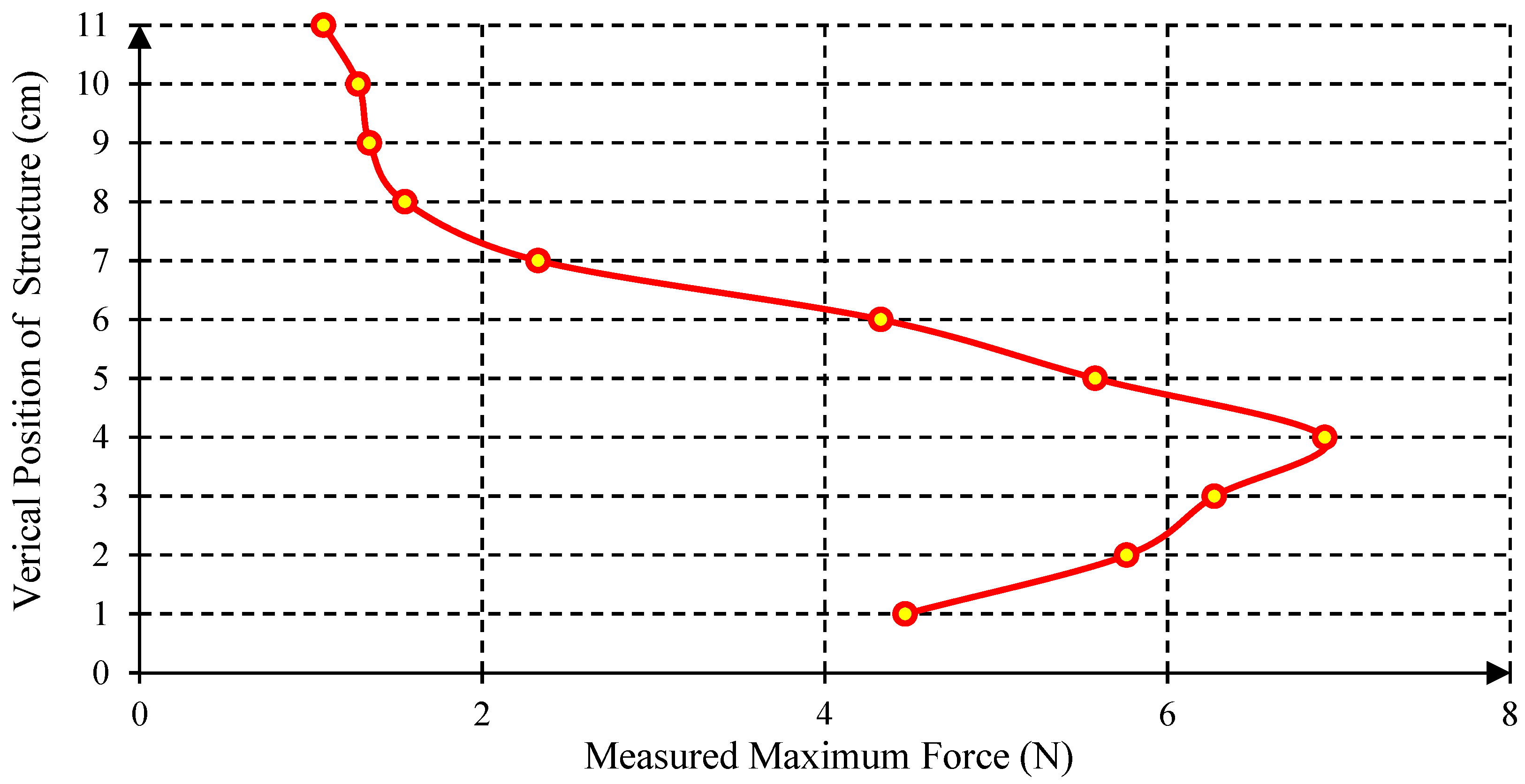
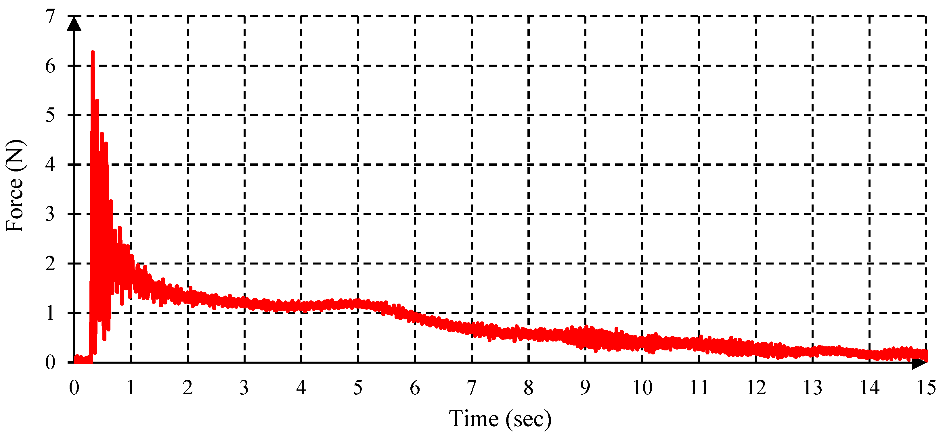
It is known that the water depth in the reservoir and the downstream water level play a crucial role in the bore generation, formation, and its propagation speed. Hence, experiments were conducted for four different reservoir water levels, namely 10 cm, 15 cm, 20 cm, and 25 cm, and labelled as H10, H15, H20, and H25, respectively (Figure 6 and Figure 7). Figure 6 also shows the size and length of the reservoir. Therefore, the effects of the reservoir water level, in other words, the effects of different bore scenarios on the hydrodynamic and maximum hydrodynamic forces acting on the structure and the duration of impact, were investigated. Moreover, the experiment was also repeated three times to investigate the effects of the location of the structure to the reservoir by placing the structure in three different locations downstream of the reservoir for each case. The locations of the structure were chosen as 14 cm, 38 cm, and 100 cm away from the gate, labelled as L14, L38, and L100, respectively in the study. In addition, measurements were taken by changing the vertical position of the coastal structure above the flume bottom at 0.5 cm intervals for each reservoir water level and the location of the structure from the gate. This was to obtain the vertical hydrodynamic load distributions for all scenarios; as known, the smaller the interval, the better the result. Hence, the vertical distance (bore height) was divided into small intervals that varied between 5 and 11 depending on the bore height. Using Equation (1), the depth-averaged hydrodynamic forces were then calculated as the arithmetic mean of the measured vertical forces for each location and for each reservoir water level. For example, the depth-averaged maximum force for case H25-L38, given in Figure 8, was calculated by taking the arithmetic mean of the vertical hydrodynamic forces at 11 vertical positions. The first vertical position of the structure was placed 1 cm above the bottom of the flume and the following positions had 0.5 cm intervals. The time averaged-forces of the depth average forces were calculated in two steps. First of all, using Equation (2), the time-averaged forces were computed as the arithmetic mean of the hydrodynamic forces over 15 s at each vertical point. For example, the time-averaged force for case H25-L38, shown in Figure 9, at vertical position 3 cm above the bed, was the arithmetic mean of the hydrodynamic forces over 15 s. Then, the time averaged-forces of the depth-averaged forces were calculated by taking the arithmetic mean of the resulting time averaged-forces in the vertical points.
F ¯ x = 1 k i = 1 k F i
F ¯ = 1 n i = 1 n F i
where F ¯ x , is the maximum depth-averaged force in the flow direction, F ¯ is the time-averaged force, F is the force in the flow direction, i is the index variable, k is the total number of vertical points, and n is the total number of time steps. The time step was 0.001 s, hence, n was taken as 15,000 for a 15 s simulation.

2.1.1. Load Cell Measurements

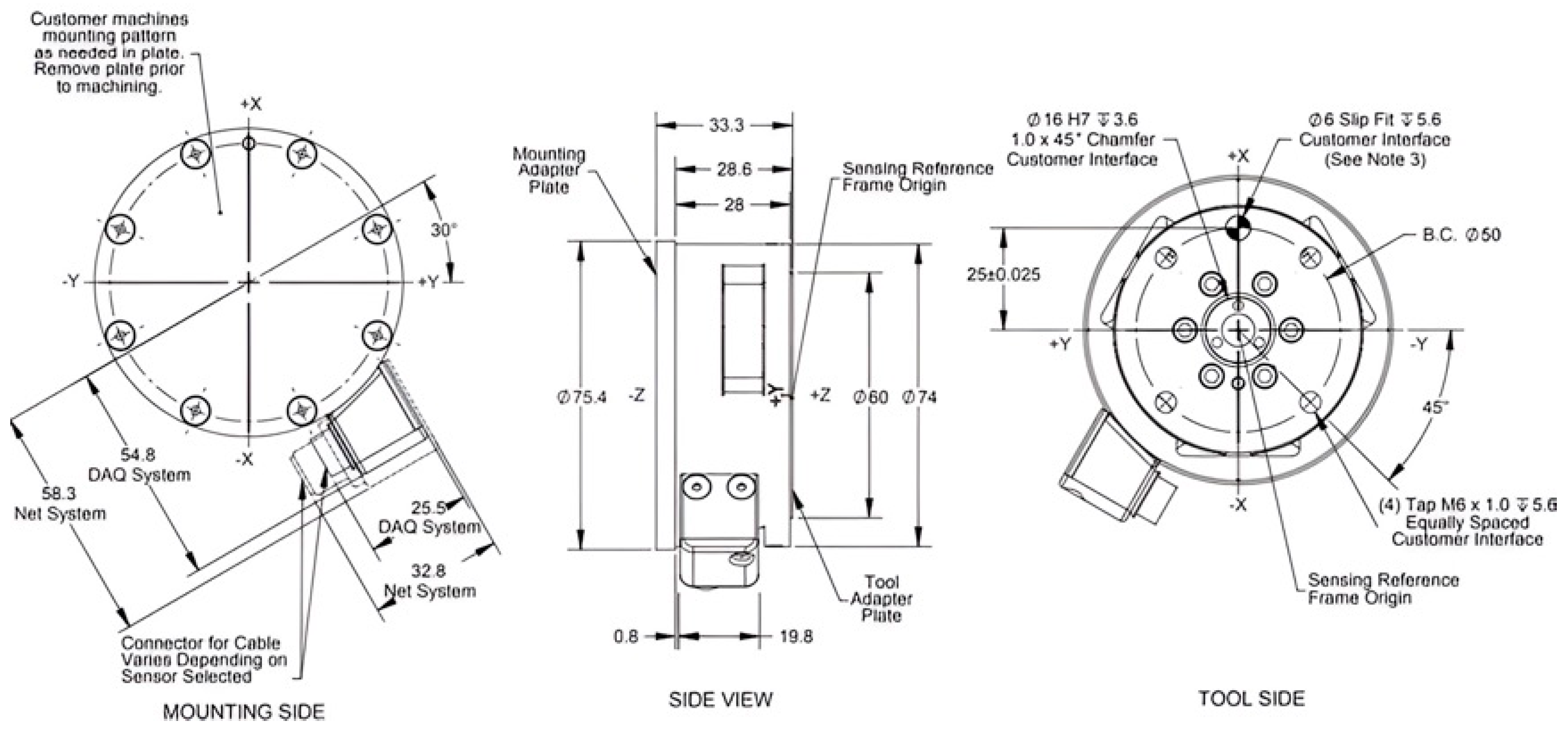
The forces and moments applied to the x, y, and z axes could be measured precisely with the six component USA ATI Mark GAMMA model SI-32-2.5 load cell (Figure 10) used in this experimental study. The load cell was 75.4 mm in diameter and 33.3 mm in height. With this load cell, the forces in horizontal directions (Fx and Fy) can be measured up to ±32 N, whereas the force in the vertical direction (Fz) can be evaluated up to ±100 N. The moments in the x, y, and z directions (Mx, My, and Mz, respectively) can be measured in the range of ±2.5 Nm. The uncertainty values of these forces and moments are given as calibration values of ±0.75%, ±1%, ±0.75%, ±1%, ±1.25%, and ±1% on the full scale, respectively [50].
During the experiments, the load cell was connected to the traverse, which aids movement in the desired direction within the flume. This movement could be controlled through the connected computer (Figure 4c), thus making it easy to position the coastal structure at desired points away from the gate and from the flume bottom. While taking measurements with the load cell, an L-shaped rod was used (Figure 4b), and the vertical component of this rod was protected by an NACA0018 type airfoil produced by using a 3D printer. The L-shaped rod ensured that the maximum load observed at the first impact was not influenced by the load on the vertical section of the rod, which was 24 cm away from the structure. The use of the airfoil was for several reasons. First, it was used to ensure that the maximum load was not more than the maximum capacity of the load cell. Second, it was used to minimize the interference of the force acting on the vertical section of the rod holding the structure. This is because the projected area and drag coefficient of the airfoil in the flow direction was less than the projected area and the drag coefficient of the circular rod exposed to the flow Finally, it helped to reduce the instabilities caused by high turbulence flow around the vertical rod.

2.1.2. Image Processing Technique

To obtain the flow depths immediately as they hit the structure, green tapes were placed on the flume glass wall at the points upstream of the structure. Then, the video recordings of the experimental study were segmented into frames. In this study, a cell-phone camera with 30 frames per second (fsp) was employed. Consequently, the video segmentation yielded 900 frames for 30 s of video recording, aligning with the specified frame rate of the camera. Figure 11 shows a sample of the frame presenting the water surface profile at the time of the impact.
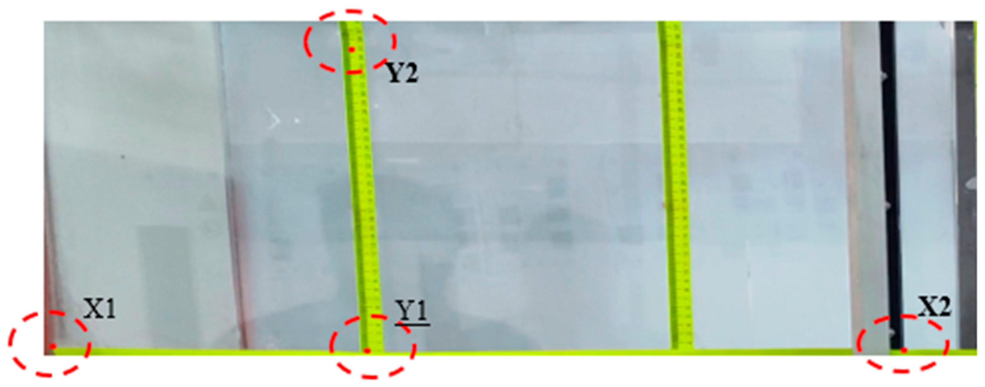
To enable precise measurements, calibration was carried out on the frame to create a connection between digital representations and real-world values. Scaling factors and offsets for pixel-to-real conversion were calculated by measuring known points on the flume to obtain the calibration data. Figure 12 shows the positions of X1, X2, Y1, and Y2 for the pixels and known values used for calibration.
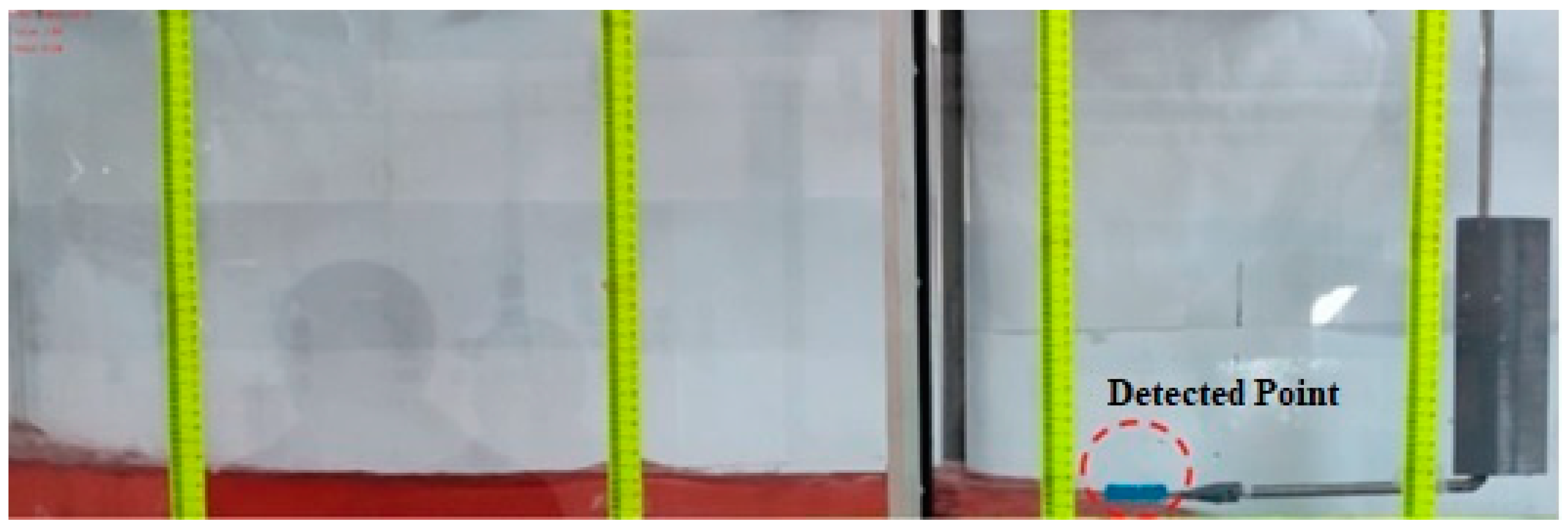
An image processing algorithm was then used to digitize the frames based on the calibrated data. This enabled the extraction of the free surface profile of the bore propagation and time history of the flow depth immediately upstream of the structure, as shown in Figure 13. The algorithm reads the frames using OpenCV and converts them into the HSV (hue, saturation, and value) color space, in order to achieve efficient color-based segmentation. Canny edge detection is then applied to the mask to detect the water surface, and the values and coordinates of the detected edges are saved in a csv file for data processing (Figure 13).

3. Results and Discussion

In this section, the forces and flow depths as well as how they were obtained from the experimental studies are presented. The findings were compared with each other and with those in the literature and discussed.

Force Measurement

In this section, the graphs showing the depth-averaged hydrodynamic force–time relationship of the bore wave impact on the coastal structure are presented for four different reservoir water levels, three different coastal structure locations downstream of the gate, and variable vertical positions of the coastal structure above the channel bed.
The depth-averaged hydrodynamic forces were obtained as the arithmetic average of forces measured at five vertical positions above the channel bed for H10, seven vertical positions for H15, nine vertical positions for H20, and eleven vertical positions for H25.
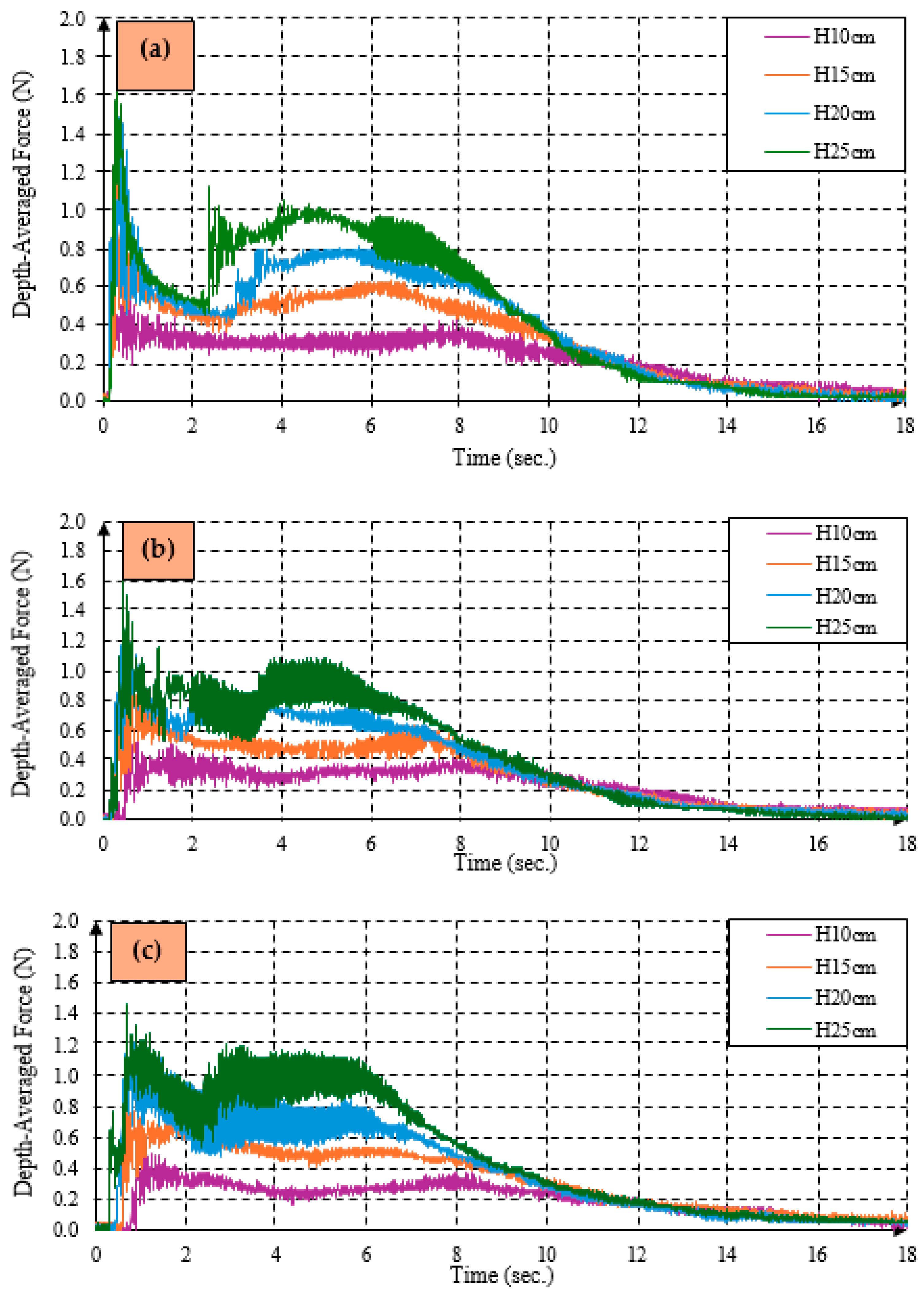
Figure 14 shows the variation in the depth-averaged hydrodynamic force over time at different reservoir water levels for each location. From the graphs, it can be seen that the maximum hydrodynamic force and the depth-averaged hydrodynamic force increased as the reservoir water level increased, independent of the structure position.
This shows that an increase in the bore properties (celerity and depth) resulting from an increase in the reservoir water level causes an increase in the depth-averaged force impacting the structure. It is a fact that the exerted force is a function of the height and celerity of the bore wave. Nevertheless, this relationship is not seen to be linear. This finding is in line with the results of Chen 2020 et al. [43] and Al-Faesly et al. [37].
Table 1 shows in detail the percentage difference in the maximum depth-averaged hydrodynamic force across the different reservoir water levels (H15, H20, and H25) with reference to H10. These results show that a 50% increase in water level results in more than a 50% increase in the maximum depth-averaged force in all scenarios. When the water depth was increased to 100%, the maximum depth-averaged hydrodynamic force also increased by more than 100%, except for the case of H20. A 150% increase in water depth was also seen to cause more than a 150% increase in the maximum depth-averaged hydrodynamic force. Table 1 also indicates that an increase in reservoir water level brought about a greater rise in the maximum depth-averaged forces on the structure closer to the gate than the structures further downstream. Hence, it could be concluded that the structures closer to the bore formation are more vulnerable to larger tsunamis.
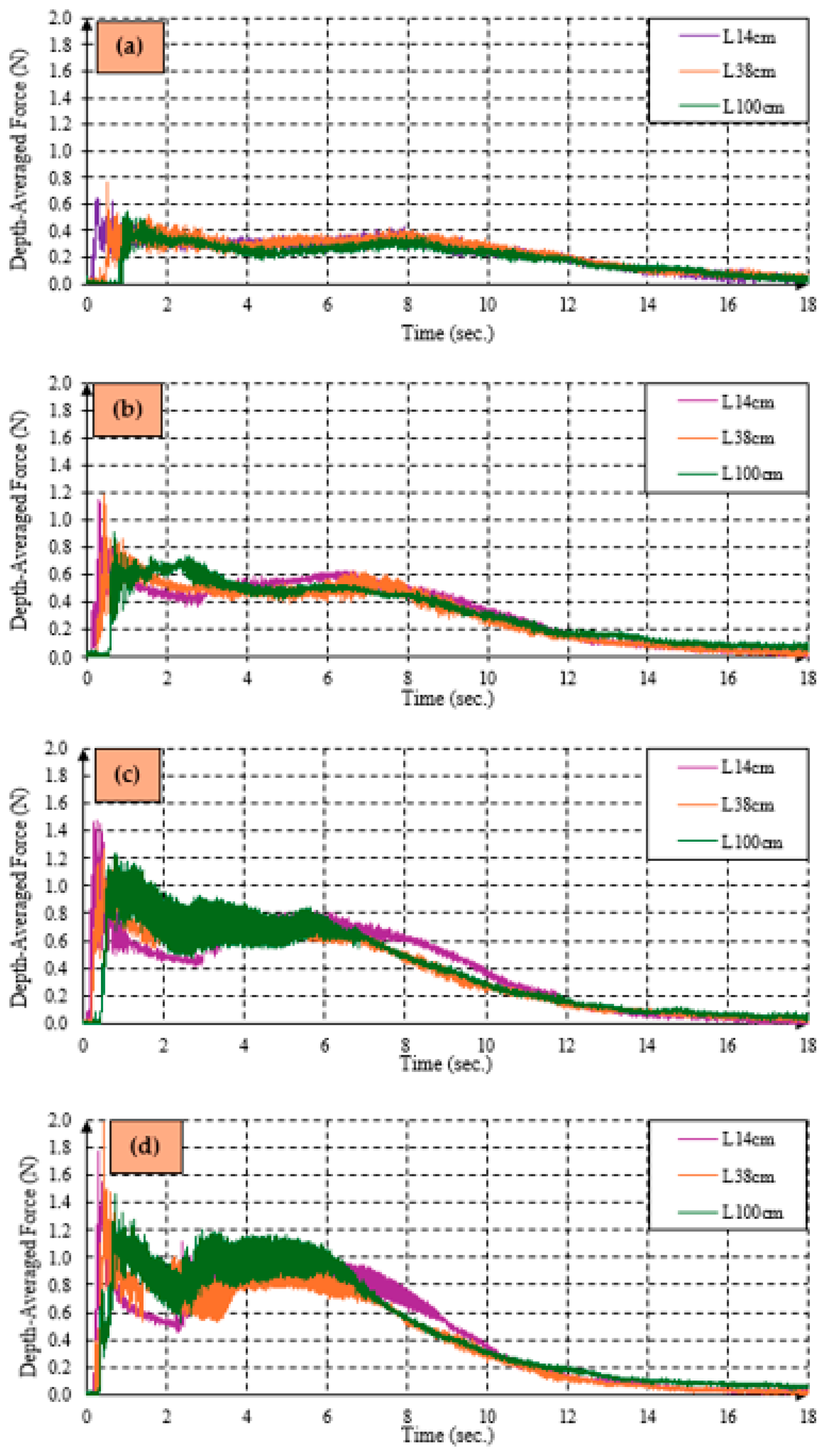
Figure 15 shows the effect of the location of the structure on the depth-averaged hydrodynamic force over a period of 18 s. It can be seen that the lowest force occurred at L100 in all scenarios. Additionally, in all three cases, the maximum depth-averaged hydrodynamic force occurred at L38; however, at H20, the maximum depth-averaged hydrodynamic force at L14 was higher than that of L38 with a difference of about 16.63%. The results recorded at L38 may be attributed to the hydrodynamic force of the bore wave, which seemed higher at this location compared with others. At L14, it seems that the bore wave was not fully developed, and this contributed to the cause of the results recorded at this structure location. In this study, the formation of the bore wave and its location were determined by analyzing the frames obtained from the image processing technique. However, further studies to precisely evaluate the location of fully developed bore waves are required.
The lowest force recorded at L100 can be due to the effect of friction in lowering the celerity of the bore wave further downstream. In addition, as indicated in Table 2, the percentage increase in the maximum force at different reservoir water levels for L14 and L38 based on the lowest force values at L100 was calculated.
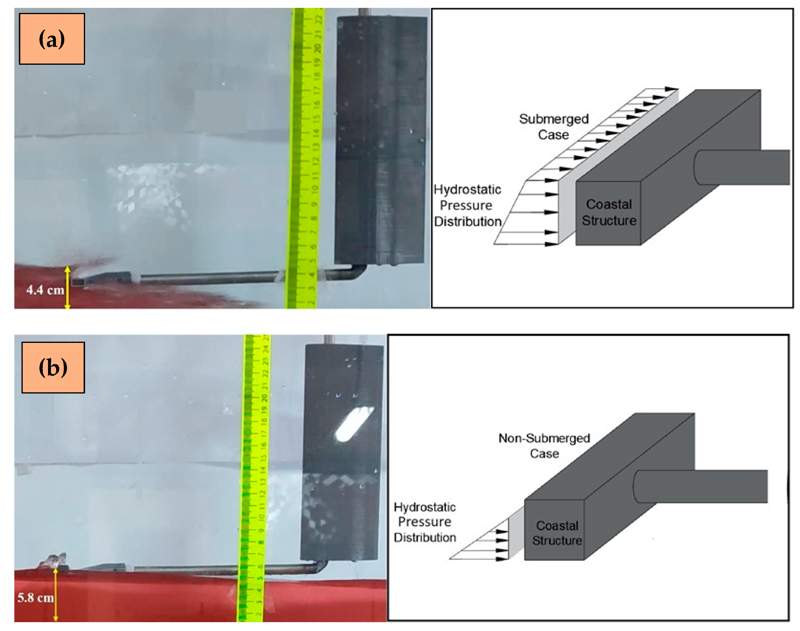
The hydrostatic forces at the occurrence time of the maximum depth-averaged hydrodynamic forces were computed, as shown in Figure 16, in order to obtain the ratio of hydrodynamic to hydrostatic forces for a comparison. The water depths in Figure 16 were extracted by using the image processing technique, and the hydrostatic forces were then computed based on the pressure distribution of the submerged or non-submerged cases, as given in Figure 16. Similar to the computation of the depth-averaged hydrodynamic forces, the depth-averaged hydrostatic forces were the arithmetic mean of the hydrostatic forces at the vertical points. The maximum ratio was found to be 14.83, and the minimum ratio was 7.47 (Table 3). It was seen that the average ratio when the reservoir water level increased from 20 to 25 rose dramatically. The average ratio varied between 10.05 and 13.38. Therefore, the bore impact forces were estimated to be equivalent to 10–13 times that of the hydrostatic forces. The overall average ratio was found to be 11.41, which is close to the range recommended by Okada et al. [17] and U.S. FEMA [19].
In Figure 15, the areas under the green, purple, and orange lines over a period of 15 s were computed. These areas indicate the intensity of the forces acting on the structure. In order to compare the duration of impact on the structure, the time-averaged forces of the depth-averaged forces over a period of 15 s were computed; this is because after 15 s, the recorded forces were found to be insignificant.
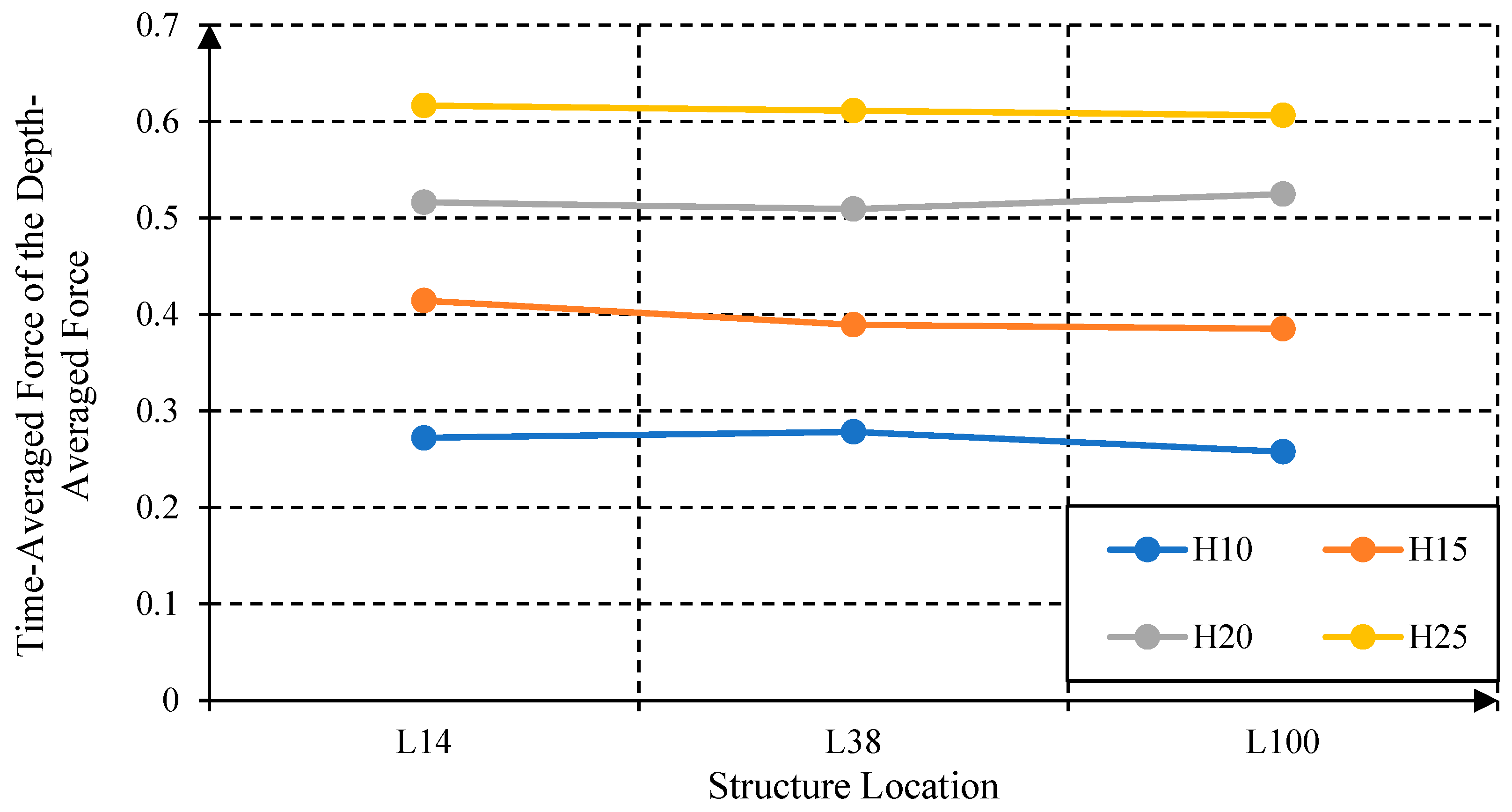
The lowest time-averaged forces of the depth-averaged forces were found at L100 in all reservoir water levels except H20, where the force was slightly higher than that of L38. This can be attributed to the bore wave celerity, which reduces with increasing propagation distance due to friction. However, according to Figure 17, contrary to the maximum depth-averaged hydrodynamic forces, the differences in the timed-averaged forces of the depth-averaged forces at each location for every reservoir water level were seen to be insignificant with a maximum difference of 0.029. It can therefore be concluded that the time-averaged forces of the depth-averaged forces acting on the structure were not much influenced by the location, given that the resistance to flow is controlled by only the small amount of bottom and side frictions, and the distance to the occurrence of the bore is short.
Table 4 shows the percentage increase calculated for different reservoir water levels and the structure locations based on the values of the time-averaged forces of the depth-averaged forces at all structure locations with respect to H10. From Table 4, it can be seen that the highest increase occurred at H25 and L100, and the lowest increase occurred at H15 and L38. It can therefore be said that an increase in the reservoir water level plays an important role in the intensity of the impact and significantly increases the time-average of the depth-averaged forces.

4. Conclusions

In this study, the effect of a bore wave on a coastal structure was experimentally examined. Measurements were taken with the help of a load cell for different horizontal and vertical positions of the coastal structure and different reservoir water levels. This study indicates that the degree of the impact of the hydrodynamic force acting on the structure depends on the following factors: bore characteristics, bottom friction, and structure location. As a result of the comparisons made for different scenarios, the following conclusions can be drawn in detail.
  • As the reservoir water level increased, the depth-averaged force impact on the structure increased. However, the percentage increase in the depth-averaged hydrodynamic forces was more than the percentage increase in the reservoir water level. Therefore, the force produced by the tsunami bore was not linearly proportional to the size of the bore.
  • When the reservoir water level rose, the resultant increase in the maximum depth-averaged force on the structure closer to the gate was found to be higher than the increase in the structures further downstream away from the gate, indicating that for larger tsunamis, the increase in the impact force would be larger for the structures closer to the bore formation than the structures further away from the bore formation.
  • The depth-averaged hydrodynamic forces were generally found to be larger at L38, where the bore was fully developed. The minimum depth-averaged hydrodynamic forces were observed at location L100 due to the friction.
  • The overall average ratio of the measured maximum depth-averaged hydrodynamic forces to the calculated hydrostatic forces was found to be very similar to the value reported in the literature. Therefore, in line with previous practical studies, this study also showed that in the design of coastal structures or onshore structures, the hydrodynamic forces could be taken as the ratio of the hydrostatic forces, which are easier to evaluate.
  • The force intensity was not significantly affected by the location of the structure, but the reservoir water level was again found to play an important role in the intensity.
  • In this study, a high volume of hydrodynamic data regarding the bore was obtained, so the data could be used not only for the validation of the numerical model to be developed, but also for the development of empirical equations for further studies.
This study was limited to the dry downstream bed with a horizontal bottom. Therefore, further studies covering wet downstream beds with varying bed slope are required to extend our conclusions for wider applications. Furthermore, measurement of the bore celerity would be helpful to analyze previously recommended empirical equations that are used in structural design.

Author Contributions

Conceptualization, K.S.E.; Methodology, K.S.E. and U.Ü.; Software, Y.E.A., U.Ü. and O.O.A.; Validation, K.S.E., U.Ü. and O.O.A.; Formal analysis, K.S.E. and U.Ü.; Investigation, K.S.E. and U.Ü.; Resources, U.Ü. and O.O.A.; Data curation, K.S.E., U.Ü. and O.O.A.; Writing—original draft preparation, K.S.E., U.Ü. and O.O.A.; Writing—review and editing, K.S.E.; Visualization, U.Ü.; Supervision, K.S.E. and Y.E.A. All authors have read and agreed to the published version of the manuscript.

Funding

This research received no external funding.

Data Availability Statement

Data is contained within the article.

Conflicts of Interest

The authors declare no conflicts of interest.

References

  1. Hayatdavoodi, M.; Liu, J.; Cengiz Ertekin, R. Bore impact on decks of coastal structures. J. Waterw. Port Coast. Ocean Eng. 2022, 148, 04021051. [Google Scholar] [CrossRef]
  2. Jones, L.; Anastasopoulos, I. Breakwater subjected to tsunami–impact: Physical modelling of geotechnical phenomena. Soil Dyn. Earthq. Eng. 2022, 159, 107344. [Google Scholar] [CrossRef]
  3. Yeh, H.; Sato, S. Tsunami effects on buildings and coastal structures. J. Disaster Res. 2016, 11, 662–669. [Google Scholar] [CrossRef]
  4. Pringgana, G. Improving Resilience of Coastal Structures Subject to Tsunami-Like Waves. Ph.D. Thesis, University of Manchester, Manchester, UK, 2016. [Google Scholar]
  5. Nistor, I.; Palermo, D.; Nouri, Y.; Murty, T.; Saatcioglu, M. Tsunami-induced forces on structures. In Handbook of Coastal and Ocean Engineering; World Scientific: Singapore, 2009; pp. 261–286. [Google Scholar]
  6. Gu, Y.; Yu, A.H.; Zheng, F.D. Numerical study of tsunami force on superstructure of offshore rigid frame box girder bridge. J. Phys. 2023, 2476, 012021. [Google Scholar] [CrossRef]
  7. Song, Y.; Jia, J.; Liu, H.; Chen, F.; Fang, Q. Numerical study on tsunami force on coastal bridge decks with superelevation. J. Mar. Sci. Eng. 2023, 11, 824. [Google Scholar] [CrossRef]
  8. Pringgana, G.; Cunningham, L.S.; Rogers, B.D. Mitigating tsunami effects on buildings via novel use of discrete onshore protection systems. Coast. Eng. J. 2023, 65, 149–173. [Google Scholar]
  9. Liu, S.; Nistor, I.; Mohammadian, A.; Azimi, A.H. Experimental and numerical investigation of beach slope effects on the hydrodynamic loading of tsunami-like surges on a vertical wall. J. Mar. Sci. Eng. 2022, 10, 1580. [Google Scholar] [CrossRef]
  10. Tanaka, N.; Igarashi, Y.; Zaha, T. Numerical investigation of the effectiveness of vegetation-embankment hybrid structures for tsunami mitigation introduced after the 2011 tsunami. Geosciences 2021, 11, 240. [Google Scholar] [CrossRef]
  11. Peng, L.; Zhang, T.; Rong, Y.; Hu, C.; Feng, P. Numerical investigation of the impact of a dam-break induced flood on a structure. Ocean Eng. 2021, 223, 108669. [Google Scholar] [CrossRef]
  12. Asadollahi, N.; Nistor, I.; Mohammadian, A. Numerical investigation of tsunami bore effects on structures, part I: Drag coefficients. Nat. Hazards 2019, 96, 285–309. [Google Scholar] [CrossRef]
  13. Cheng, D.; Zhao, X.Z.; Zhang, D.K.; Chen, Y. Numerical study of dam-break induced tsunami-like bore with a hump of different slopes. China Ocean Eng. 2017, 31, 683–692. [Google Scholar] [CrossRef]
  14. Li, Y.L.; Ma, Y.; Deng, R.; Jiang, D.P.; Hu, Z. Research on dam-break induced tsunami bore acting on the triangular breakwater based on high order 3D CLSVOF-THINC/WLIC-IBM approaching. Ocean Eng. 2019, 182, 645–659. [Google Scholar] [CrossRef]
  15. St-Germain, P.; Nistor, I.; Townsend, R. Numerical modeling of the impact with structures of tsunami bores propagating on dry and wet beds using the SPH method. Int. J. Prot. Struct. 2012, 3, 221–255. [Google Scholar] [CrossRef]
  16. Wei, Z.; Dalrymple, R.A.; Hérault, A.; Bilotta, G.; Rustico, E.; Yeh, H. SPH modeling of dynamic impact of tsunami bore on bridge piers. Coast. Eng. 2015, 104, 26–42. [Google Scholar] [CrossRef]
  17. Okada, T.; Sugano, T.; Ishikawa, T.; Ohgi, T.; Takai, S.; Hamabe, C. Structural Design Methods of Buildings for Tsunami Resistance (SMBTR); The Building Center of Japan: Osaka, Japan, 2005. [Google Scholar]
  18. USACE: US Army Coastal Engineering. Wave Forces on a Wall Shoreward of the Still Water Level; Technical Note III-29; US Army Corps of Engineers, Coastal Engineering Research Centre: Vicksburg, MS, USA, 1990. [Google Scholar]
  19. US FEMA: Federal Emergency Management Agency. Coastal Construction Manual; FEMA P-55 (Vol. II); US FEMA: Federal Emergency Management Agency: Washington, DC, USA, 2011. [Google Scholar]
  20. Robertson, I.N.; Carden, L.P.; Chock, G.Y. Case study of tsunami bore impact on RC wall. In Proceedings of the 32nd International Conference on Ocean, Offshore and Arctic Engineering, Nantes, France, 8–13 June 2013. [Google Scholar]
  21. Mizutani, S.; Imamura, F. Dynamic wave force of tsunamis acting on a structure. In Proceedings of the ITS 2001 Proceedings, Seattle, Washington, 7–10 August 2001; pp. 941–948. [Google Scholar]
  22. Linton, D.; Gupta, R.; Cox, D.; Van de Lindt, J.; Oshnack, M.E.; Clauson, M. Evaluation of tsunami loads on wood-frame walls at full scale. J. Struct. Eng. 2013, 139, 1318–1325. [Google Scholar] [CrossRef]
  23. Rahman, S.; Akib, S.; Khan, M.T.R.; Shirazi, S.M. Experimental study on tsunami risk reduction on coastal building fronted by sea wall. Sci. World J. 2014, 7, 729357. [Google Scholar] [CrossRef]
  24. Arnason, H. Interactions between an Incident Bore and a Free-Standing Coastal Structure; University of Washington: Seattle, WA, USA, 2005; p. 172. [Google Scholar]
  25. Kihara, N.; Niida, Y.; Takabatake, D.; Kaida, H.; Shibayama, A.; Miyagawa, Y. Large-scale experiments on tsunami-induced pressure on a vertical tide wall. Coast. Eng. 2015, 99, 46–63. [Google Scholar] [CrossRef]
  26. Santo, J.; Robertson, I.N. Lateral Loading on Vertical Structural Elements Due to a Tsunami Bore; University of Hawaii: Honolulu, HI, USA, 2010. [Google Scholar]
  27. Robertson, I.; Paczkowski, K.; Riggs, H.; Mohamed, A. Tsunami bore forces on walls. In Proceedings of the 30th International Conference on Ocean, Offshore and Arctic Engineering, Rotterdam, The Netherlands, 19–24 June 2011; pp. 395–403. [Google Scholar]
  28. Thusyanthan, N.; Madabhushi, G.S. Tsunami wave loading on coastal houses: A model approach. Civ. Eng. 2008, 161, 77–86. [Google Scholar] [CrossRef]
  29. Huo, Z.; Liu, H. Experimental study of the surge- and bore-induced impact pressure on a vertical wall and its foundation. Phys. Fluids 2023, 35, 016602. [Google Scholar] [CrossRef]
  30. Rajaie, M.; Azimi, A.H.; Nistor, I.; Rennie, C.D. Experimental investigations of the impact of tsunami-like hydraulic bores on a square structure. I: Pore pressure variations. J. Waterw. Port Coast. Ocean Eng. 2023, 149, 04022027. [Google Scholar] [CrossRef]
  31. Maqtan, R.; Yusuf, B.; Hamzah, S.B. Physical modeling of landward scour due to tsunami bore overtopping seawall. MATEC Web Conf. 2018, 203, 01003. [Google Scholar] [CrossRef]
  32. Shafiei, S.; Melville, B.W.; Shamseldin, A.Y.; Adams, K.N.; Beskhyroun, A.S. Experimental investigation of tsunami-borne debris impact force on structures: Factors affecting impulse-momentum formula. Ocean Eng. 2016, 127, 158–169. [Google Scholar] [CrossRef]
  33. Li, X.; Liu, H. Experimental study on the dam-break-induced surge impact on an inclined wall. Phys. Fluids 2024, 36, 047105. [Google Scholar] [CrossRef]
  34. Wüthrich, D.; Pfister, M.; Nistor, I.; Schleiss, A.J. Experimental study of tsunami-like waves generated with a vertical release technique on dry and wet beds. J. Waterw. Port Coast. Ocean Eng. 2018, 144, 04018006. [Google Scholar] [CrossRef]
  35. Rajaie, M.; Azimi, A.H.; Nistor, I.; Rennie, C.D. Experimental investigations on hydrodynamic characteristics of tsunami-like hydraulic bores impacting a square structure. J. Hydraul. Eng. 2022, 148, 04021061. [Google Scholar] [CrossRef]
  36. Wüthrich, D.; Pfister, M.; Nistor, I.; Schleiss, A.J. Experimental study on the hydrodynamic impact of tsunami-like waves against impervious free-standing buildings. Coast. Eng. J. 2018, 60, 180–199. [Google Scholar] [CrossRef]
  37. Al-Faesly, T.; Palermo, D.; Nistor, I.; Cornett, A. Experimental modeling of extreme hydrodynamic forces on structural models. Int. J. Prot. Struct. 2012, 3, 477–505. [Google Scholar] [CrossRef]
  38. Chuang, W.L.; Chang, K.A.; Kaihatu, J.; Cienfuegos, R.; Mokrani, C. Experimental study of force, pressure, and fluid velocity on a simplified coastal building under tsunami bore impact. Nat. Hazards 2020, 103, 1093–1120. [Google Scholar] [CrossRef]
  39. Cross, R.H. Tsunami surge forces. J. Waterw. Harb. Div. 1967, 93, 201–231. [Google Scholar] [CrossRef]
  40. Chanson, H. Tsunami surges on dry coastal plains: Application of dam break wave equations. Coast. Eng. J. 2006, 48, 355–370. [Google Scholar] [CrossRef]
  41. Chanson, H.; Aoki, S.I.; Maruyama, M. Experimental Investigations of Wave Runup Downstream of Nappe Impact: Applications to Flood Wave Resulting from Dam Overtopping and Tsunami Wave Runup; Coastal/Ocean Engineering Report; Toyohashi University of Technology: Toyohashi, Japan, 2000. [Google Scholar]
  42. Benazir, B.; Triatmadja, R.; Rahardjo, A.P.; Yuwono, N. The behavior of a tsunami-like wave produced by dam break and its run-upon 1:20 slope. J. Tsunami Soc. Int. 2019, 38, 49–67. [Google Scholar]
  43. Chen, C.; Chen, J.; Lin, P.; Chen, C.; Chen, H. Experimental study of dam-break-like tsunami bore impact mechanism on a container model. Pol. Marit. Res. 2020, 1, 53–59. [Google Scholar] [CrossRef]
  44. Elsheikh, N.; Nistor, I.; Azimi, A.H.; Mohammadian, A. Tsunami-induced bore propagating over a canal—Part 1: Laboratory experiments and numerical validation. Fluids 2022, 7, 213. [Google Scholar] [CrossRef]
  45. Erduran, K.S.; Kutija, V.; Hewett, C.J.M. Performance of finite volume solutions to the shallow water equations with shock-capturing schemes. Int. J. Numer. Methods Fluids 2002, 40, 1237–1273. [Google Scholar] [CrossRef]
  46. Erduran, K.S.; Ünal, U.; Dokuz, A.Ş. Experimental and numerical investigation of partial dam-break waves. Ocean Eng. 2024, 308, 118346. [Google Scholar] [CrossRef]
  47. Erduran, K.S.; Dokuz, A.Ş.; Ünal, U. Performance analysis of a hybrid numerical wave model based on experimental results obtained by image processıng technique. Omer Halisdemir Univ. J. Eng. Sci. 2019, 8, 183–196. (In Turkish) [Google Scholar]
  48. Erduran, K.S.; Ünal, U.; Dokuz, A.Ş.; Nas, M.Ç. Experimental and numerical investigation of the effect on the water surface profiles of bridge pier type and skew angle. Konya J. Eng. Sci. 2023, 11, 41–58. (In Turkish) [Google Scholar] [CrossRef]
  49. Lauber, G.; Hager, W.H. Experiments to dam break wave: Horizontal channel. J. Hydraul. Res. 1998, 36, 291–307. [Google Scholar] [CrossRef]
  50. Bayındırlı, C.; Akansu, Y.E.; Salman, M.S. The determination of aerodynamic drag coefficient of truck and trailer model by wind tunnel tests. Int. J. Automot. Eng. Technol. 2016, 5, 53–60. [Google Scholar] [CrossRef]
  51. URL-1: ATI Industrial Automation F/T Sensor: Gamma. Available online: https://www.ati-ia.com/app_content/Documents/9230-05-1329.auto.pdf (accessed on 10 July 2024).
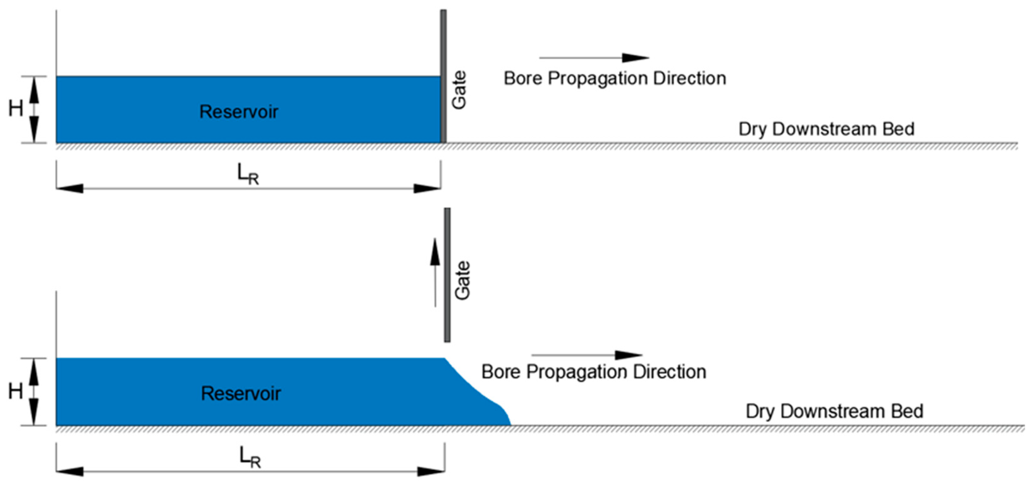
Figure 1. Schematic view of bore wave propagation resulting from dam break.
Hydrology 11 00131 g001
Figure 2. General view of the flume used in experimental studies.
Hydrology 11 00131 g002
Figure 3. Gate opening mechanism.
Hydrology 11 00131 g003
Figure 4. Hydrodynamic force measurement: (a) coastal structure and load cell; (b) coastal structure and NACA0018 airfoil; (c) traverse system.
Hydrology 11 00131 g004
Figure 5. Measuring gate opening time: (a) limit switches; (b) Arduino system and power supply; (c) LCD screen.
Hydrology 11 00131 g005
Figure 6. Schematic view of dam break scenarios for the experimental studies: (a) plan view; (b) longitudinal cross section view.
Hydrology 11 00131 g006
Figure 7. Longitudinal view of the experimental setup.
Hydrology 11 00131 g007
Figure 8. Vertical hydrodynamic load distribution for H25-L38.
Hydrology 11 00131 g008
Figure 9. Time variation of hydrodynamic force at a vertical position 3 cm above the bed.
Hydrology 11 00131 g009
Figure 10. USA ATI mark GAMMA model SI-32-2.5 load cell [51].
Hydrology 11 00131 g010
Figure 11. Frame sample showing the water surface profile at the impact time.
Hydrology 11 00131 g011
Figure 12. Position definition for the x and y axis.
Hydrology 11 00131 g012
Figure 13. Frame showing the detected water surface.
Hydrology 11 00131 g013
Figure 14. Depth-averaged hydrodynamic force for different reservoir water levels: (a) L14; (b) L38; (c) L100.
Hydrology 11 00131 g014
Figure 15. Depth-averaged hydrodynamic force for different locations: (a) H10; (b) H15; (c) H20; (d) H25.
Hydrology 11 00131 g015
Figure 16. Calculation of hydrostatics forces: (a) submerged case; (b) non-submerged case.
Hydrology 11 00131 g016
Figure 17. Time-averaged hydrodynamic forces of the depth-averaged hydrodynamic forces for different locations.
Hydrology 11 00131 g017
Table 1. Percentage increase in the maximum depth-averaged hydrodynamic force for different reservoir water levels with respect to H10.
H15H20H25
L1476.58127.07172.52
L3854.1564.89158.04
L10067.89127.16169.29
All values are in percentage (%).
Table 2. Percentage increase in the maximum depth-averaged hydrodynamic force for different locations with respect to L100.
L14L38
H1019.1740.71
H1525.3429.19
H2019.132.14
H2520.6034.83
All values are in percentage (%).
Table 3. The ratio of the depth-averaged maximum hydrodynamic forces to hydrostatic forces.
Reservoir Water
Level
Hydrodynamic Force (N)Hydrostatic Force
(N)
RatioAverage Ratio
L14L38L100L14L38L100L14L38L100
H100.64990.76730.54530.0870.0570.0507.4713.5510.8310.62
H151.14761.18290.91560.0860.1080.08813.4110.9410.3811.58
H201.47581.26531.23880.1150.1670.12712.807.599.7710.05
H251.77111.98011.46860.1190.1680.10914.8311.7913.5013.38
Overall Average Ratio11.41
Table 4. Percentage increase in force intensity for different locations with respect to H10.
L14L38L100
H1552.2939.8649.39
H2089.7382.99103.55
H25126.54119.58135.16
All values are in percentage (%).
Disclaimer/Publisher’s Note: The statements, opinions and data contained in all publications are solely those of the individual author(s) and contributor(s) and not of MDPI and/or the editor(s). MDPI and/or the editor(s) disclaim responsibility for any injury to people or property resulting from any ideas, methods, instructions or products referred to in the content.