Article

Mathematical Modeling and Experiments on Pyrolysis of Walnut Shells Using a Fixed-Bed Reactor

School of Engineering and Natural Sciences, University of Iceland, VR-II, Hjardarhaga 6, 107 Reykjavik, Iceland
*
Authors to whom correspondence should be addressed.
ChemEngineering 2022, 6(6), 93; https://doi.org/10.3390/chemengineering6060093
Submission received: 29 October 2022 / Revised: 15 November 2022 / Accepted: 29 November 2022 / Published: 1 December 2022
(This article belongs to the Special Issue Thermal Treatment of Biomass and Solid Municipal Waste)

Abstract

:
Pyrolysis is a low-emission and sustainable thermochemical technique used in the production of biofuels, which can be used as an alternative to fossil fuels. Understanding the kinetic characterization of biomass pyrolysis is essential for process upscaling and optimization. There is no accepted model that can predict pyrolysis kinetics over a wide range of pyrolysis conditions and biomass types. This study investigates whether or not the classical lumped kinetic model with a three-competitive reaction scheme can accurately predict the walnut shell pyrolysis product yields. The experimental data were obtained from walnut shell pyrolysis experiments at different temperatures (300–600 °C) using a fixed-bed reactor. The chosen reaction scheme was in good agreement with our experimental data for low temperatures, where the primary degradation of biomass occurred (300 and 400 °C). However, at higher temperatures, there was less agreement with the model, indicating that some other reactions may occur at such temperatures. Hence, further studies are needed to investigate the use of detailed reaction schemes to accurately predict the char, tar, and gas yields for all types of biomass pyrolysis.

1. Introduction

Due to worldwide energy concerns, the depletion of fossil fuels, as well as environmental problems associated with their use, renewable energy sources are receiving increased attention. Biomass has been recognized as an alternative to fossil fuels due to its global availability and environmental benefits, which provide the main motivation for the conversion of biomass into fuels. This conversion can be achieved through biochemical conversion (anaerobic digestion [1,2], fermentation [3]), and thermochemical conversion (combustion [4], pyrolysis [5], and gasification [6,7]). Unlike biochemical transformation, the thermochemical method can convert various types of biomass into fuels or chemicals in an efficient, sustainable, and quick way [8]. However, the use of biomass in traditional combustion processes is limited due to its low energy density and release of toxic organic compounds, such as dioxins [9,10].
Pyrolysis is a low-emission and sustainable thermochemical technique that can be used to thermally degrade biomass into a range of useful products, including bio-char (solid), pyrolysis oil/tars, and fuel gas products (volatiles) [11]. In addition to being an independent technology, biomass pyrolysis is the main sub-process in combustion and gasification processes. As pyrolysis is an inevitable process in thermochemical biomass conversion, understanding pyrolysis kinetics is important for process development, optimization, and proper reactor design.
Kinetics plays an important role in understanding the complex pyrolysis process and deriving mathematical models. Numerous studies have investigated the kinetics of pyrolysis processes [12,13]. Pyrolysis of biomass involves a highly complex set of competitive and concurrent reactions, and the exact mechanism remains unknown. There is no conventional model that can predict the pyrolysis rate or provide initial information about final conversion yields over a varied range of biomass types, pyrolysis conditions, and reactors types [14]. Hence, simple models that can describe pyrolysis kinetics are very beneficial.
This paper investigates the use of a simple lumped model to mathematically simulate the reaction kinetics of the slow pyrolysis of walnut shells. While lumped models do not necessarily represent the complex physicochemical mechanism of the process, they are able to predict the overall yields [15,16]. A lumped model is acceptable for determining the kinetic parameters of reactions involving pyrolysis, combustion, and gasification [17]. In such models, biomass components and their reaction products are categorized into three product groups: solid (char), non-condensable volatiles (gas), and liquid (tar) [18].
There are two main mathematical approaches to experimentally determine the kinetic parameters of biomass pyrolysis: iso-conversional (model-free) [19,20,21] and model-based (model-fitting) [22] methods. Model-fitting methods can be categorized as one-component or multi-component depending on the initial biomass characterization (biomass type or its components) and as lumped or detailed reaction mechanisms according to how the products are defined (by products or by species in each product) [23]. The present work combines experimental and theoretical studies on walnut shell pyrolysis. Nutshells as potential materials can be used as an alternative fuel. While studies have evaluated the kinetics of nutshell thermal decomposition [24,25], many have used different reaction mechanisms and kinetic models [26].
Sheth et al. [27] validated the model previously proposed by Koufopanos [28] to optimize the kinetic parameters of the hazelnut shell pyrolysis experiments conducted by Demirbas [29], which involved thermogravimetry experiments on hazelnut shells at heating rates of 0.5, 2, 10, 25, and 40 K/s. Noszczyk et al. [26] conducted thermogravimetric analyses at three different heating rates (5, 10, and 20 °C·min−1) on walnut, hazelnut, peanut, and pistachio shells. The kinetic parameters were determined by Coats and Redfern [30] using the isothermal model-fitting method. Their results showed that an increase in the heating rate caused an increase in the activation energy of nut shell pyrolysis. They concluded that there is a significant difference in the kinetic parameters of different feed materials, even those from the waste classes (e.g., nutshell wastes). They recommended characterizing specific nutshell residues to improve the modeling of thermal processes and reactor design for thermal waste treatment [30].
So far, few studies have been conducted on the pyrolysis of walnut shells using a fixed-bed reactor. To the best of our knowledge, no research has been performed on lumped kinetic modeling of nut shells, especially walnut shells. Therefore, the aim of this work was to apply the lumped kinetic model proposed by many authors [15,16,31] to accurately determine the kinetic parameters of walnut shells pyrolysis. The objectives of this research were as follows: (1) conduct slow pyrolysis experiments on walnut shells in a fixed-bed reactor, (2) estimate the kinetic parameters of the walnut shell pyrolysis. Then, based on a comparison of the modeling and experimental results, we will study whether the existing three-reaction competitive scheme has sufficient prediction power for gas, tar, and char yields across the temperature range of 300 to 600 °C.

2. Materials and Methods

2.1. Pyrolysis Experiment

Walnut shells were chosen as the pyrolysis material. The samples were chopped up and sieved into small particles with sizes ranging from 1 to 2 mm, dried in an oven at 105 °C for 48 h to remove any moisture, and then kept in a desiccator prior to the experiments to ensure that they remained dry. Based on the proximate analysis of the samples, walnut shells had 37.9% fixed carbon and 59.3% volatile matter on a dry and ash-free basis [32]. It is assumed that any moisture uptake that might have occurred during the handling of the samples prior to the experiments would have been eliminated due to the slow heating rate of the process (0.25 °C·s−1), as thermal decomposition starts at around 180–200 °C.
The pyrolysis experiments were carried out on a fixed-bed reactor, as shown in Figure 1. The system consists of vertically positioned stainless steel tubes. A tube (350 mm and 8 mm ID) was connected to the reactor tube (50 mm and 6 mm ID), where the pyrolysis of the biomass occurs, and a U-style tar trap (6 mm ID) was connected to the reactor. The tar trap was submerged in the cooling bath for the duration of the experiment to condense and collect tar. Power was delivered via copper clamps attached to the outside of the stainless steel tube body at the top and bottom of the tube. The tube body acted as a resistance heater. The samples were held in place between two stainless steel wire meshes, placed in the middle of the reactor tube, and kept constant for all the tests. A layer of quartz wool was placed on top of the tar tube in order to separate the tar from other pyrolysis gases. The controller, the power supply, and the K-type thermocouple were arranged in a loop. The controller modulated the direct current onto the stainless steel tube, which was resistively heated to regulate the heating rate and control the temperature. The required experimental parameters, such as the heating rate, holding time, and temperature, were entered in the control program. Holding temperatures of 300 °C, 400 °C, 500 °C, and 600 °C were used in this study. A heating rate of 0.25 °C·s−1 and a holding time of 100 s were used for all of the experiments. A K-type thermocouple was used to measure and control the temperature. The thermocouple was introduced through a fitting connection at the top of the tube. The cooling bath used for pyrolysis vapor condensation contained a mixture of dry ice and ethylene glycol (the temperature of the bath was −60 °C). In order to achieve the desired temperature, volume fractions of 0.4 and 0.6 of dry-ice and ethylene glycol were used, respectively [33]. Another thermocouple was placed at the top of the tar trap to measure the temperature during the experiment and to ensure the trap was cool enough to capture tars. Argon (Ar) was used as a carrier gas, at a 3 L/min flow rate, from the top of the stainless steel tube to sweep away pyrolysis products. Argon was selected as the carrier gas, as it does not condense at a temperature of −60 °C.

Product Yield Calculations

At the end of the run, the reactor was left to cool naturally to room temperature, and products were collected to calculate char and tar yields. The tar collection method using solvents and rotary evaporators was avoided due to concerns of losing some tars due to the relatively high temperature of the rotary evaporators [34]. The difference in weight of the reactor tube and tar trap before and after the experiments was calculated as the mass of chars and tars, respectively. Gas yields were calculated by difference to close the mass balance. The experiments were repeated two times for each condition and then the mean values were obtained. The product yields were calculated using Equations (1)–(3):
C h a r   y i e l d   w t % = m c h a r m i n i t i a l   s a m p l e × 100  
T a r   y i e l d   w t % = m t a r m i n i t i a l   s a m p l e × 100
G a s   y i e l d   w t % = 100 C h a r   y i e l d T a r   y i e l d  

2.2. Mathematical Modeling

Model-based methods are the most common methods used for evaluating solid-state kinetics, especially in non-isothermal conditions. With these methods, a reaction scheme must be proposed first (see Figure 2). This study used the competitive model, which is a common reaction scheme for representing the components of pyrolysis by simply lumping them into three groups of products (gas, tar, and char) [15,35].
The rate of reaction of the solid phase under non-isothermal conditions (Equation (4)) is determined by multiplying k(T), a process rate constant that obeys the Arrhenius law, and f(α), the conversion function depending on the reaction mechanism [36]. This study used first-order reaction f(α) = 1 − α. i = 1, 2, 3.
  d α d t = k i T f α  
The degree of conversion (α) represents the sample decomposition amount at time t and is defined in terms of the sample’s mass change (Equation (5)), where m0 is the initial mass, mt is the mass at an arbitrary time, and m is the mass at the end of the process.
α = m 0 m t m 0 m
The rate constant is described by the Arrhenius equation (Equation (6)), where A is the pre-exponential factor (s−1), E is the activation energy (kJ·mol−1), R is the universal gas constant (kJ·K−1·mol−1), and T is the absolute temperature (K).
k i T = A i exp E i R T  
The linear heating rate under non-isothermal conditions β is calculated using Equation (7), where dT is a temperature change (K) and dt is a time change (s).
β = d T d t
Nonlinear least squares fitting is commonly employed to estimate Arrhenius parameters by fitting the experimental data. Differential measurements are suggested for this method for better demonstration of solid de-volatilization [37]. We searched for values of the unknown parameters (Ai, Ei) that minimized the sums of the squares of the experimental data (final yields of gas, tar, and char at the final temperature) and determined the corresponding points of functions calculated (at the final temperature) by the model (see Equation (8)) [38]. n represents the total number of experimental data.
s u m = i = 1 n ( d α i d t e x p e r i m e n t d α i d t m o d e l ) 2
A large number of estimated pyrolysis kinetic parameters have been reported in the literature. Reported activation energies (kJ·mol−1) vary from 112.7 to 140 for E1, 84 to 133 for E2, 106.5 to 121 for E3, and pre-exponential factors from (s−1) 4.1 × 10 6 to 1.48 × 10 10 A1, 1.43 × 10 4   to 2 × 10 8   for A2 and 7.4 × 10 5   to 2.66 × 10 10 for A3 [31,39,40]. The kinetic parameters (Ai, Ei, in total 6 parameters) in this study were fitted by minimizing the sum in Equation (8) using nonlinear optimization with the generalized reduced gradient method, subject to the constraints obtained from the literature mentioned above. The motivation for using these constraints was to ensure that all the parameters remained within the physically realistic range based on the existing literature. This variation in reported values is due to the fact that the researchers used different models, feeds, operation conditions, and heating profiles. [14]. Table 1 presents the primary kinetic parameters and other constants used in the model. Primary kinetic parameters were obtained from a study using lumped model for wood pyrolysis [39].

3. Results and Discussion

3.1. Pyrolysis Experiments

Pyrolysis of walnut shells was conducted using a fixed-bed reactor. The process was performed at different temperatures (300–600 °C), with the heating rate of 0.25 °C·s−1 and a holding time of 100 s.

3.1.1. Vapor-Condensing Temperature and Condensing Efficiency

Figure 3 shows the data collected from the thermocouples, including the pyrolysis process and tar trap temperatures versus the time of the pyrolysis. The cooling bath exhibited good heat preservation performance with the right volume fractions of dry ice and ethylene glycol. During pyrolysis, the bath temperature gradually increased from −30 °C to the final temperature of 2 °C, which is well below the tar trap limit (30 °C) temperature reported in the literature [34]. Wang et al. found the optimum condensing temperature to be in the range of 67 to 77 °C, at which point the moisture in the pyrolysis oil decreased from 30% to 10% and the condensing efficiency was in the range of 0.4 to 0.2 [41].
Condensation efficiency in this study was calculated using Equation (9) [41], and the result was around 0.25 for all the experiments, which is in the optimum range [41].
C o n d e n s i n g   e f f i c i e n c y = L i q u i d   m a s s W a l n u t   s h e l l   m a s s s o l i d   m a s s
where liquid mass denotes the mass of condensed tar in the tar trap, walnut shell mass specifies the mass of raw materials prior to pyrolysis, and solid mass represents the mass of char after pyrolysis.

3.1.2. Pyrolysis Products and the Effect of Temperature

The effect of temperature (in the range of 300–600 °C) on the quantity of pyrolysis products formed from walnut shells has been studied, as it is the most significant factor related to the pyrolytic product distribution and yield.
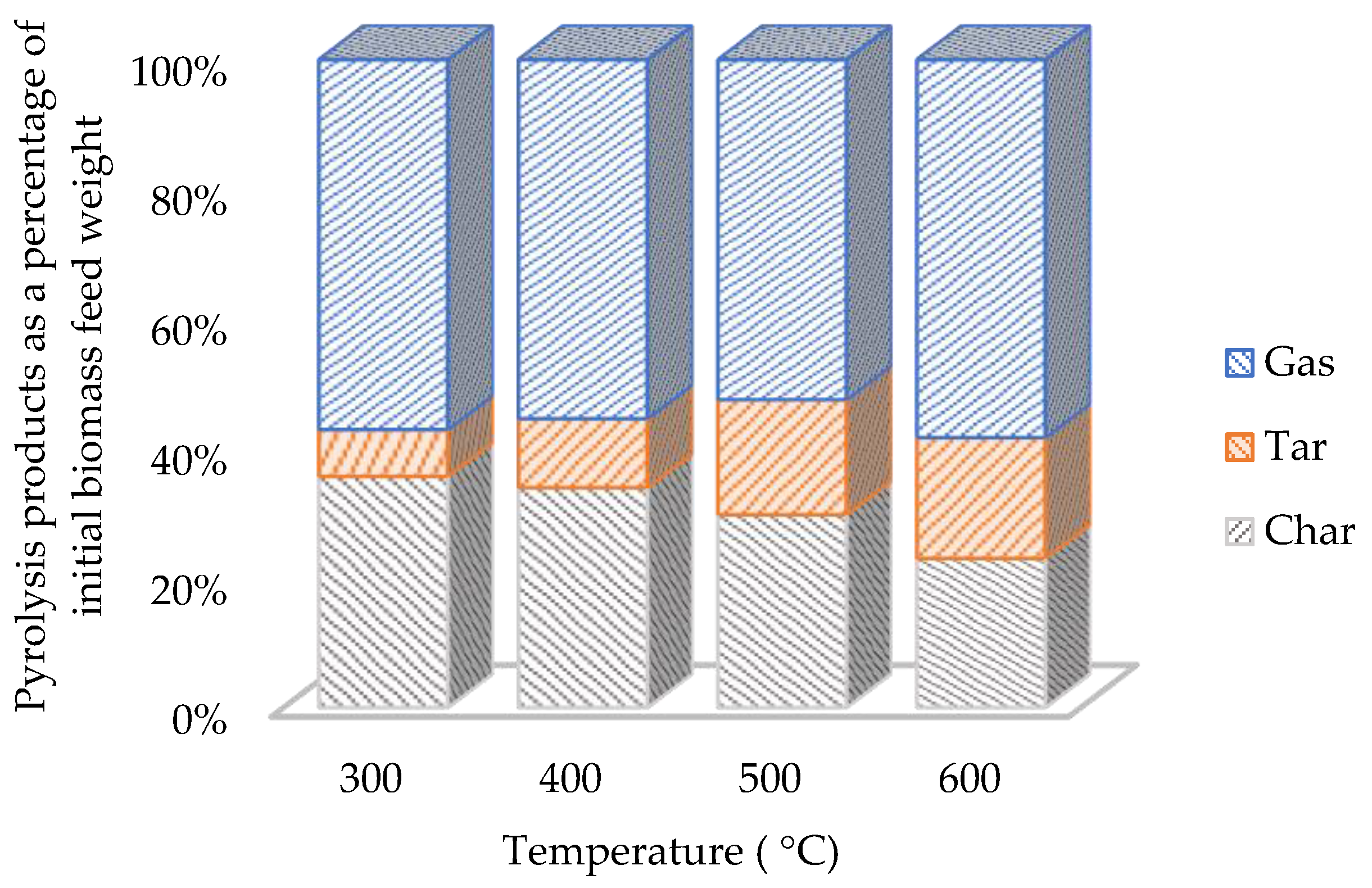
The tar and char yields were measured after each test, and the results are shown in Figure 4. The gas yield was calculated as the percentage of the balance between the original sample weight and the weights of tar and char formed. Volatile yields (volatile yield is the sum of the gas and tar yields) increased as the temperature increased. The ideal pyrolysis temperature for maximum tar yields is reported to be between 400–600 °C for most types of woody biomass [42]. The tar yields doubled when pyrolysis was carried out between 400–500 °C. There was a major increase in tar yields up to 500 °C, but by 600 °C the yield reached a maximum value of 19%. Efeovbokhan et al. [43] observed that tar yields increased by more than double when the temperature was in the range of 400–500 °C for pyrolyzing yam peels. The gas yields were high, with approximately half of the feedstock being converted to gas. The high char yields, measured at the low temperatures in the range studied, decreased up to 23% of the total biomass feed. This indicates that the optimum temperature range for char production from pyrolysis of walnut shells is up to 400 °C. Temperature negatively affects char production yields [44]. Sarkar et al. [45] studied the pyrolysis of coconut shells in the temperature range of 400–600 °C and reported the char yield reduced while bio-oil yield was improved with the temperature increase.

3.2. Pyrolysis Modeling

The simple lumped kinetic model was chosen to evaluate the accuracy of pyrolysis reaction kinetics and product yield prediction. The kinetic parameters of each reaction in the reaction scheme of the competitive model were determined with a least squares method by fitting experimental data at different temperatures. The kinetic parameters from Chan et al. [39] were employed as the primary values. The initial values for the fitting were the kinetic parameters determined for the case of a first-order reaction. The best values of the estimated kinetic parameters (3 activation energies and 3 pre-exponential factors) are shown in Table 2. The subscripts 1, 2, and 3 are the kinetic parameters of the reactions: solid to gas, solid to tar, and solid to char, respectively. The estimated kinetic parameters are within the range of values reported in the literature. Sheth et al. [46] conducted kinetic modeling on woody biomass decomposition to volatiles and char. Their chosen reaction scheme used two competing reactions for each biomass component. Sheth et al. then applied the least squares method to find the optimum kinetic parameters. They described this approach to modelling biomass decomposition as a failure since the kinetic parameters (Ai, Ei) they obtained with their model and methodology were not within the predetermined physically realistic range.
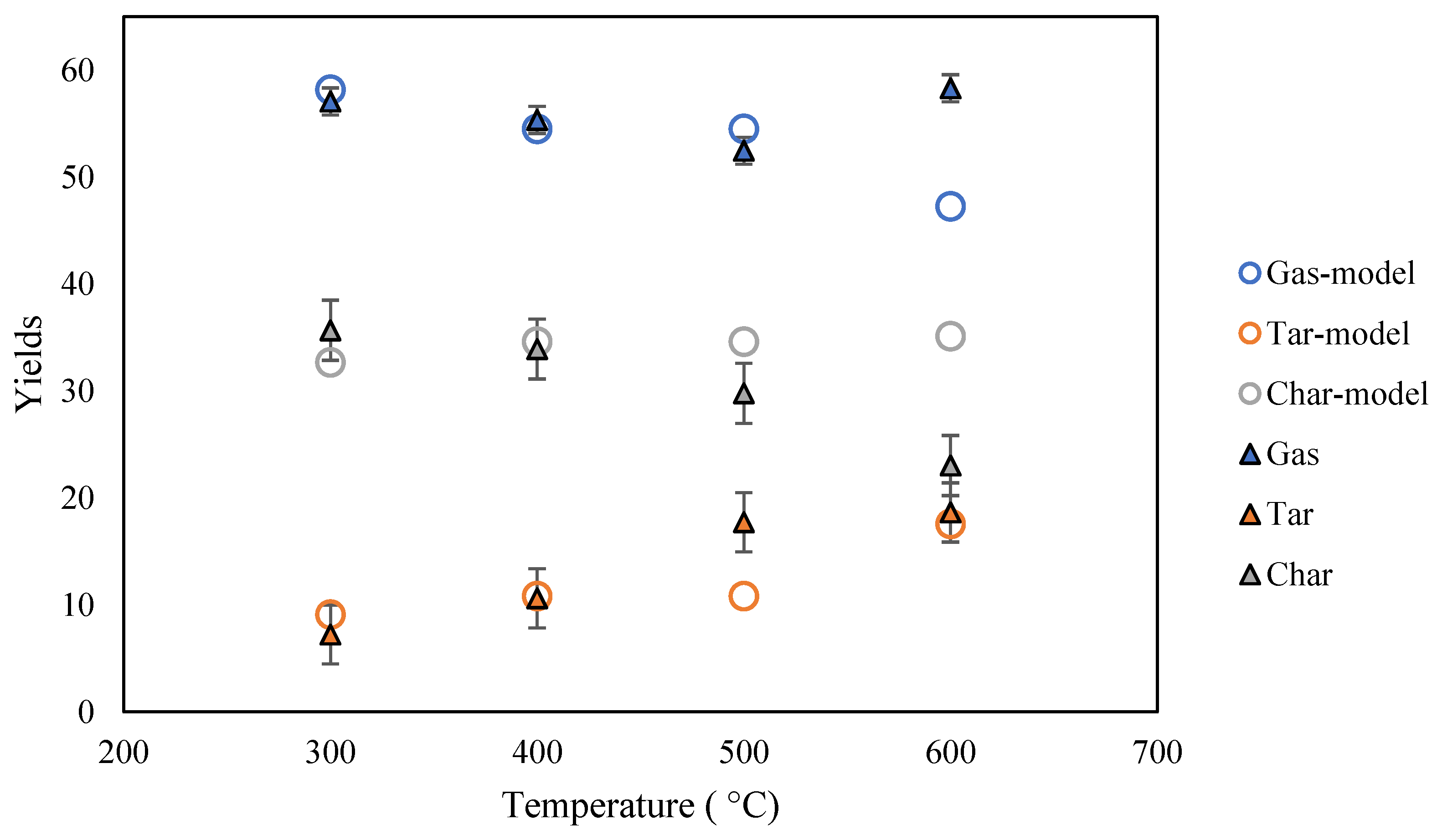
Figure 5 compares the model-predicted yields with the experimentally measured yields. The model used the best-fit parameters in Table 2. The modeling data confirmed that the solid yield dropped while the tar and gas yields enhanced during the experiments in the temperature range of 300 to 400 °C. The fit of the model to the experimental data for the pyrolysis temperatures of 300 and 400 °C was sufficiently good. At higher temperatures, there was less agreement with the model, which could indicate that some other reactions dominate at such temperatures. The first-order Arrhenius kinetics focus on the primary pyrolysis process; consequently, the kinetics scheme better represents the primary decomposition of biomass pyrolysis [47]. In pyrolysis processes, biomass moisture loss occurs at temperatures below 100 °C; primary pyrolysis reactions occur at 200–600 °C, where biomass decomposes into the primary char, primary tars, and non-condensable gas; and secondary pyrolysis reactions occur at 300–800 °C [48]. This study found that the one-component mechanism with three competing reactions is not a suitable scheme for the slow pyrolysis of walnut shell at high temperatures. As one-component kinetic mechanisms are mostly used for describing pyrolysis under fast heating rates or/and high temperatures, the disagreement could be eliminated if a different reaction mechanism was chosen [49].
The average percentage error from the experimental data was calculated using Equation (10) [50]. At low temperatures, the model and experimental results agreed well, with an average percentage error of 3% for the low-temperature data. This indicates the model performs well in the temperature range of 300 to 400 °C. Based on this result and the studies on lumped kinetic modeling in the same temperature range, average percentage error typically achieves results within 5%.
A v e r a g e   p e r c e n t a g e   e r r o r = i = 1 n d a t a e x p e r i m e n t d a t a m o d e l d a t a e x p e r i m e n t × 100 n
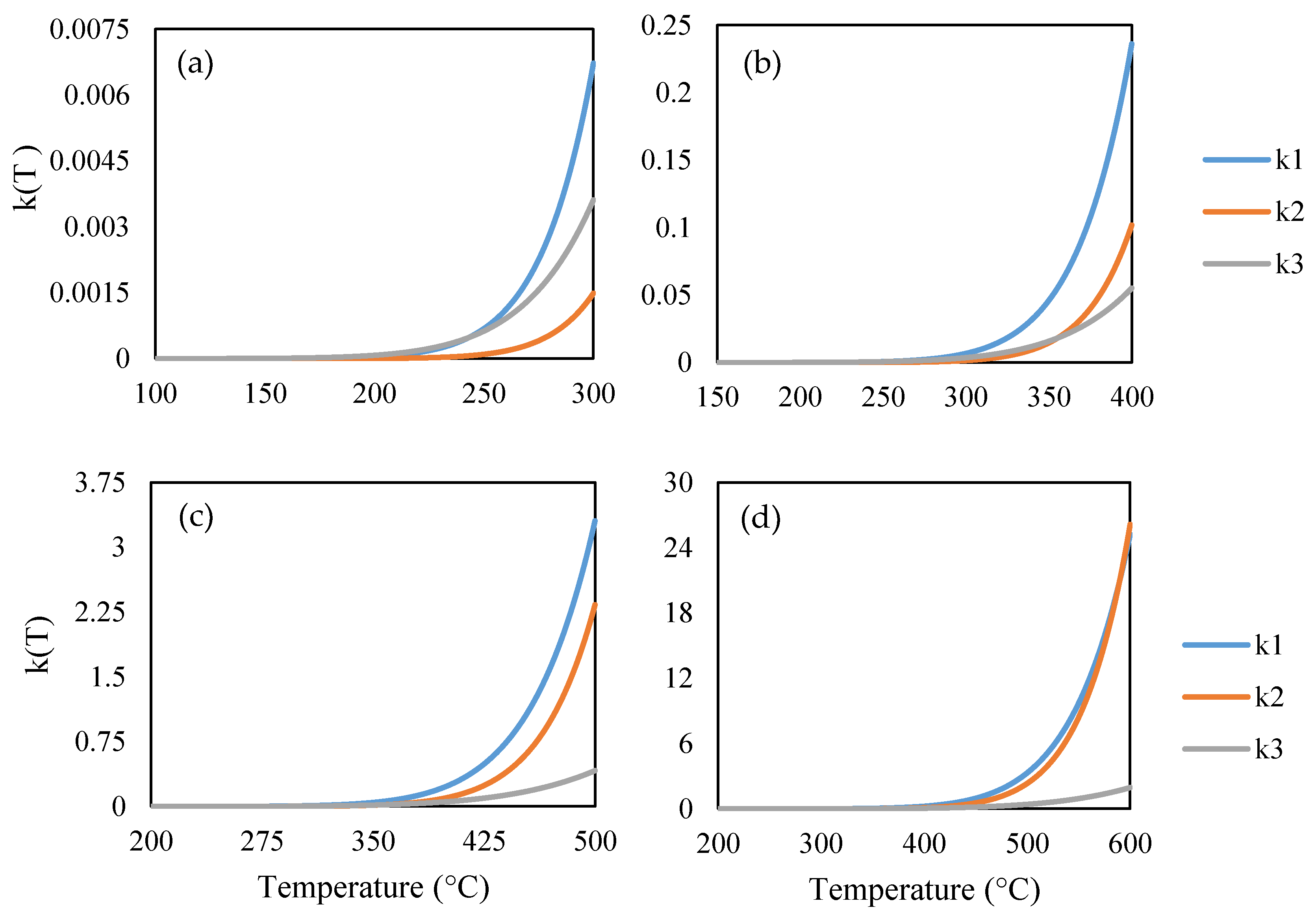
In Figure 6, we plot the temperature-dependent rate constants   k i T over different temperature ranges. We show these somewhat unconventional plots because the plots reveal how reactions 1, 2, and 3, responsible for the formation of the three phases (gas, liquid, solid), take over or dominate in different temperature ranges. For example, one might expect that the solid formation (char) would dominate at the lowest temperatures, liquid formation (tar) would dominate in the central (pyrolysis) range, and gas formation would take over at the high end as it approaches gasification temperatures. This trend does hold for char k 3 T , but according to our model and data k 2 T is dominant up to 600 °C. This suggests that k 1 T largely corresponds to volatilization. In a sense, we may have averaged out or missed the effect of gasification reactions at higher temperatures.

4. Conclusions

Pyrolysis experiments and mathematical modeling of walnut shells were conducted. No previous studies have investigated the application of lumped-kinetic modeling to simulate walnut shell pyrolysis product yields. The experimental work was conducted at different temperatures (300–600 °C) in a fixed-bed reactor. According to the experiments, char yields dropped from 37% to 23% with the temperature increase, while volatile yields (tar and gas) increased from 64% to 77%, respectively. We used the nonlinear least squares fitting method to determine the kinetic parameters of the reactions involved. The conventional competitive reaction scheme with three reactions fit our experimental data well at low temperatures, where the primary degradation of biomass occurred (300 and 400 °C), but not at higher temperatures. The results here suggest that the competitive reaction model with three reactions needs to be expanded to include the secondary decomposition of pyrolysis products to accurately predict yields as gasification temperatures are approached. This will be explored in a future work that will be published soon.

Author Contributions

A.S.: Conceptualization, formal analysis, validation, investigation, methodology, writing—original draft. C.R.: supervision, writing—review and editing. R.U.: funding acquisition, supervision, writing—review and editing. All authors have read and agreed to the published version of the manuscript.

Funding

This research was funded by the Icelandic Technology Development Fund, grant number 175326 and the University of Iceland Eimskip fund, grant number 151200.

Data Availability Statement

Not applicable.

Conflicts of Interest

The authors declare no conflict of interest.

References

  1. Safavi, S.M.; Unnthorsson, R. Methane yield enhancement via electroporation of organic waste. Waste Manag. 2017, 66, 61–69. [Google Scholar] [CrossRef] [PubMed]
  2. Safavi, S.M.; Unnthorsson, R. Enhanced methane production from pig slurry with pulsed electric field pre-treatment. Environ. Technol. 2017, 39, 479–489. [Google Scholar] [CrossRef] [PubMed]
  3. Birol, G.; Önsan, Z.İ.; Kırdar, B.; Oliver, S.G. Ethanol production and fermentation characteristics of recombinant saccharomyces cerevisiae strains grown on starch. Enzyme Microb. Technol. 1998, 22, 672–677. [Google Scholar] [CrossRef]
  4. Moliner, C.; Bove, D.; Arato, E. Co-Incineration of Rice Straw-Wood Pellets: A Sustainable Strategy for the Valorisation of Rice Waste. Energies 2020, 13, 5750. [Google Scholar] [CrossRef]
  5. Monteiro Nunes, S.; Paterson, N.; Dugwell, D.R.; Kandiyoti, R. Tar formation and destruction in a simulated downdraft, fixed-bed gasifier: Reactor design and initial results. Energy Fuels 2007, 21, 3028–3035. [Google Scholar] [CrossRef]
  6. Ouadi, M.; Brammer, J.G.; Kay, M.; Hornung, A. Fixed bed downdraft gasification of paper industry wastes. Appl. Energy 2013, 103, 692–699. [Google Scholar] [CrossRef] [Green Version]
  7. Rollinson, A.N.; Williams, O. Experiments on torrefied wood pellet: Study by gasification and characterization for waste biomass to energy applications. R. Soc. Open Sci. 2016, 3, 150578. [Google Scholar] [CrossRef] [Green Version]
  8. Zhang, X.-S.; Yang, G.-X.; Jiang, H.; Liu, W.-J.; Ding, H.-S. Mass production of chemicals from biomass-derived oil by directly atmospheric distillation coupled with co-pyrolysis. Sci. Rep. 2013, 3, 1120. [Google Scholar] [CrossRef] [Green Version]
  9. Safavi, S.M.; Richter, C.; Unnthorsson, R. Dioxin and Furan Emissions from Gasification. In Gasification; IntechOpen: London, UK, 2021. [Google Scholar]
  10. Safavi, A.; Richter, C.; Unnthorsson, R. Dioxin Formation in Biomass Gasification: A Review. Energies 2022, 15, 700. [Google Scholar] [CrossRef]
  11. Basu, P. Biomass Gasification, Pyrolysis and Torrefaction Practical Design and Theory, 2nd ed.; Elsevier: Amsterdam, The Netherlands, 2013. [Google Scholar]
  12. Çepelioğullar, Ö.; Haykiri-Açma, H.; Yaman, S. Kinetic modelling of RDF pyrolysis: Model-fitting and model-free approaches. Waste Manag. 2016, 48, 275–284. [Google Scholar] [CrossRef]
  13. Gouws, S.M.; Carrier, M.; Bunt, J.R.; Neomagus, H.W.J.P. Lumped chemical kinetic modelling of raw and torrefied biomass under pressurized pyrolysis. Energy Convers. Manag. 2022, 253, 115199. [Google Scholar] [CrossRef]
  14. Koufopanos, C.A.; Lucchesi, A.; Maschio, G. Kinetic modelling of the pyrolysis of biomass and biomass components. Can. J. Chem. Eng. 1989, 67, 75–84. [Google Scholar] [CrossRef]
  15. Di Blasi, C.; Branca, C. Kinetics of Primary Product Formation from Wood Pyrolysis. Ind. Eng. Chem. Res. 2001, 40, 5547–5556. [Google Scholar] [CrossRef]
  16. Wagenaar, B.M.; Prins, W.; van Swaaij, W.P.M. Flash pyrolysis kinetics of pine wood. Fuel Process. Technol. 1993, 36, 291–298. [Google Scholar] [CrossRef] [Green Version]
  17. Ranzi, E.; Dente, M.; Goldaniga, A.; Bozzano, G.; Faravelli, T. Lumping procedures in detailed kinetic modeling of gasification, pyrolysis, partial oxidation and combustion of hydrocarbon mixtures. Prog. Energy Combust. Sci. 2001, 27, 99–139. [Google Scholar] [CrossRef]
  18. Vikram, S.; Rosha, P.; Kumar, S. Recent modeling approaches to biomass pyrolysis: A review. Energy Fuels 2021, 35, 7406–7433. [Google Scholar] [CrossRef]
  19. Friedman, H.L. Kinetics of thermal degradation of char-forming plastics from thermogravimetry. Application to a phenolic plastic. J. Polym. Sci. Part C Polym. Symp. 2007, 6, 183–195. [Google Scholar] [CrossRef]
  20. Kissinger, H.E. Variation of peak temperature with heating rate in differential thermal analysis. J. Res. Natl. Bur. Stand. 1956, 57, 217. [Google Scholar] [CrossRef]
  21. Fawzy, S.; Osman, A.I.; Farrell, C.; Al-Muhtaseb, A.H.; Harrison, J.; Al-Fatesh, A.S.; Fakeeha, A.H.; Rooney, D.W. Kinetic modelling for pyrolytic conversion of dedicated short rotation woody crop with predictions for isothermal, non-isothermal and stepwise heating regimes. Appl. Energy Combust. Sci. 2022, 9, 100048. [Google Scholar] [CrossRef]
  22. Vo, T.A.; Ly, H.V.; Tran, Q.K.; Kwon, B.; Kim, S.S.; Kim, J. Lumped-kinetic modeling and experiments on co-pyrolysis of palm kernel cake with polystyrene using a closed-tubing reactor to upgrade pyrolysis products. Energy Convers. Manag. 2021, 249, 114879. [Google Scholar] [CrossRef]
  23. Di Blasi, C. Modeling chemical and physical processes of wood and biomass pyrolysis. Prog. Energy Combust. Sci. 2008, 34, 47–90. [Google Scholar] [CrossRef]
  24. Zubkova, V.; Strojwas, A.; Bielecki, M.; Kieush, L.; Koverya, A. Comparative study of pyrolytic behavior of the biomass wastes originating in the Ukraine and potential application of such biomass. Part 1. Analysis of the course of pyrolysis process and the composition of formed products. Fuel 2019, 254, 115688. [Google Scholar] [CrossRef]
  25. Yi, L.; Liu, H.; Li, S.; Li, M.; Wang, G.; Man, G.; Yao, H. Catalytic pyrolysis of biomass wastes over Org-CaO/Nano-ZSM-5 to produce aromatics: Influence of catalyst properties. Bioresour. Technol. 2019, 294, 122186. [Google Scholar] [CrossRef] [PubMed]
  26. Noszczyk, T.; Dyjakon, A.; Koziel, J.A. Kinetic parameters of nut shells pyrolysis. Energies 2021, 14, 682. [Google Scholar] [CrossRef]
  27. Sheth, P.; Babu, B. Pyrolysis of Hazelnut Shell: Kinetic Modeling And Simulation; Chemical Engineering Group, Birla Institute of Technology and Science: Rajasthan, India, 2007. [Google Scholar]
  28. Koufopanos, C.A.; Papayannakos, N.; Maschio, G.; Lucchesi, A. Modelling of the pyrolysis of biomass particles. Studies on kinetics, thermal and heat transfer effects. Can. J. Chem. Eng. 1991, 69, 907–915. [Google Scholar] [CrossRef]
  29. Demirbaş, A. Kinetics for non-isothermal flash pyrolysis of hazelnut shell. Bioresour. Technol. 1998, 66, 247–252. [Google Scholar] [CrossRef]
  30. Coats, A.W.; Redfern, J.P. Kinetic Parameters from Thermogravimetric Data. Nature 1964, 201, 68–69. [Google Scholar] [CrossRef]
  31. Thurner, F.; Mann, U. Kinetic investigation of wood pyrolysis. Ind. Eng. Chem. Process Des. Dev. 1981, 20, 482–488. [Google Scholar] [CrossRef]
  32. Demirbaş, A. Fuel Characteristics of Olive Husk and Walnut, Hazelnut, Sunflower, and Almond Shells. Energy Sources 2002, 24, 215–221. [Google Scholar] [CrossRef]
  33. Harris, H.H.; Lee, D.W.; Jensen, C.M. Cost-Effective Teacher Dry-Ice Bath Based on Ethylene Glycol Mixtures. J. Chem. Educ. 2000, 77, 2000. [Google Scholar]
  34. Nunes, S.M.; Paterson, N.; Herod, A.A.; Dugwell, D.R.; Kandiyoti, R. Tar Formation and Destruction in a Fixed Bed Reactor Simulating Downdraft Gasification: Optimization of Conditions. Energy Fuels 2008, 22, 1955–1964. [Google Scholar] [CrossRef]
  35. Papari, S.; Hawboldt, K. A review on the pyrolysis of woody biomass to bio-oil: Focus on kinetic models. Renew. Sustain. Energy Rev. 2015, 52, 1580–1595. [Google Scholar] [CrossRef]
  36. Fogler, H.S. Elements of Chemical Reaction Engineering, 3rd ed.; Pearson Educacion: Singapore, 2004; ISBN 81-203-2234-7. [Google Scholar]
  37. Varhegyi, G.; Antal, M.J.; Szekely, T.; Szabo, P. Kinetics of the thermal decomposition of cellulose, hemicellulose, and sugarcane bagasse. Energy Fuels 1989, 3, 329–335. [Google Scholar] [CrossRef]
  38. Várhegyi, G.; Antal, M.J.; Jakab, E.; Szabó, P. Kinetic modeling of biomass pyrolysis. J. Anal. Appl. Pyrolysis 1997, 42, 73–87. [Google Scholar] [CrossRef] [Green Version]
  39. Chan, W.-C.R.; Kelbon, M.; Krieger, B.B. Modelling and experimental verification of physical and chemical processes during pyrolysis of a large biomass particle. Fuel 1985, 64, 1505–1513. [Google Scholar] [CrossRef]
  40. Di Blasi, C. Modeling and simulation of combustion processes of charring and non-charring solid fuels. Prog. Energy Combust. Sci. 1993, 19, 71–104. [Google Scholar] [CrossRef]
  41. Wang, C.; Luo, Z.; Diao, R.; Zhu, X. Study on the effect of condensing temperature of walnut shells pyrolysis vapors on the composition and properties of bio-oil. Bioresour. Technol. 2019, 285, 121370. [Google Scholar] [CrossRef]
  42. Bhoi, P.R.; Ouedraogo, A.S.; Soloiu, V.; Quirino, R. Recent advances on catalysts for improving hydrocarbon compounds in bio-oil of biomass catalytic pyrolysis. Renew. Sustain. Energy Rev. 2020, 121, 109676. [Google Scholar] [CrossRef]
  43. Efeovbokhan, V.E.; Akinneye, D.; Ayeni, A.O.; Omoleye, J.A.; Bolade, O.; Oni, B.A. Experimental dataset investigating the effect of temperature in the presence or absence of catalysts on the pyrolysis of plantain and yam peels for bio-oil production. Data Br. 2020, 31, 105804. [Google Scholar] [CrossRef]
  44. Dhar, S.A.; Sakib, T.U.; Hilary, L.N. Effects of pyrolysis temperature on production and physicochemical characterization of biochar derived from coconut fiber biomass through slow pyrolysis process. Biomass Convers. Biorefinery 2022, 12, 2631–2647. [Google Scholar] [CrossRef]
  45. Sarkar, J.K.; Wang, Q. Different Pyrolysis Process Conditions of South Asian Waste Coconut Shell and Characterization of Gas, Bio-Char, and Bio-Oil. Energies 2020, 13, 1970. [Google Scholar] [CrossRef]
  46. Sheth, P.; Babu, B. Kinetic Modeling, Simulation and Optimization of Pyrolysis. In Proceedings of the International Symposium & 61st Annual Session of IIChE in Association with International Partners (CHEMCON-2008), Panjab University, Chandigarh, India, 27 December 2008; pp. 27–30. [Google Scholar]
  47. Park, W.C.; Atreya, A.; Baum, H.R. Experimental and theoretical investigation of heat and mass transfer processes during wood pyrolysis. Combust. Flame 2010, 157, 481–494. [Google Scholar] [CrossRef]
  48. Xia, C.; Cai, L.; Zhang, H.; Zuo, L.; Shi, S.Q.; Lam, S.S. A review on the modeling and validation of biomass pyrolysis with a focus on product yield and composition. Biofuel Res. J. 2021, 8, 1296–1315. [Google Scholar] [CrossRef]
  49. Mate, M. Numerical Modelling of Wood Pyrolysis; Royal Institute of Technology: Stockholm, Sweden, 2016. [Google Scholar]
  50. Babu, B.V.; Chaurasia, A.S. Modeling for pyrolysis of solid particle: Kinetics and heat transfer effects. Energy Convers. Manag. 2003, 44, 2251–2275. [Google Scholar] [CrossRef]
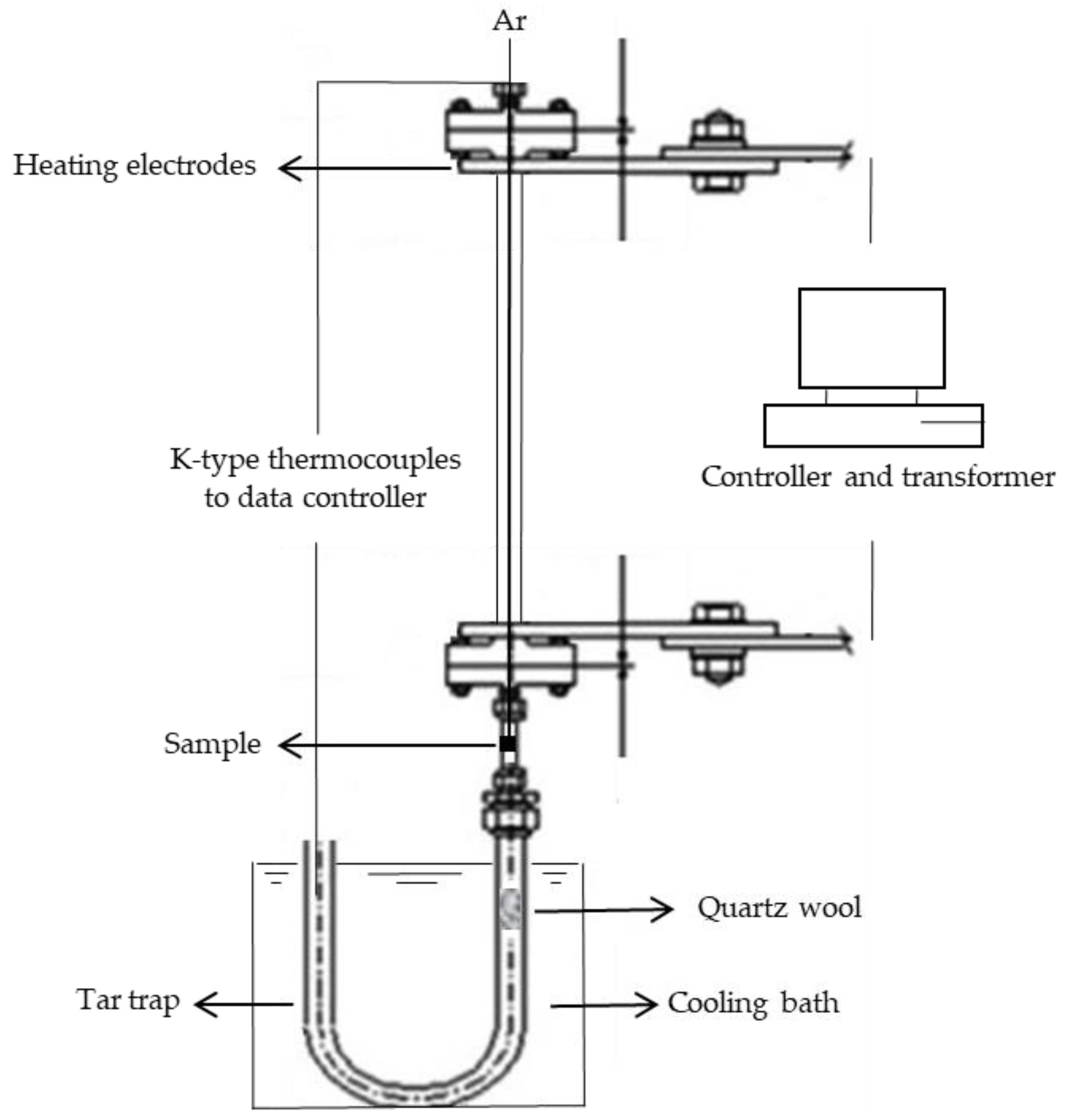
Figure 1. Fixed-bed reactor setup for the pyrolysis process.
Chemengineering 06 00093 g001
Figure 2. The competitive model with three reactions in the reaction scheme.
Chemengineering 06 00093 g002
Figure 3. Pyrolysis process and tar trap temperatures versus time of pyrolysis.
Chemengineering 06 00093 g003
Figure 4. Distribution of the products generated during pyrolysis at different temperatures. Each test was performed in duplicate.
Chemengineering 06 00093 g004
Figure 5. Comparison between experimental data and yields predicted by the model during pyrolysis as a function of maximum pyrolysis temperature.
Chemengineering 06 00093 g005
Figure 6. The reaction rate constants (s−1) versus temperature (K): (a) for the temperature range 100 °C to 300 °C; (b) for the temperature range 150 °C to 400 °C; (c) for the temperature of range 200 °C to 500 °C; and (d) for the temperature range 200 °C to 600 °C.
Chemengineering 06 00093 g006
Table 1. Primary kinetic data and other constants that are used in the model.
ParametersValues
A1 (s−1)1.30 × 10⁸
A2 (s−1)2.00 × 10⁸
A3 (s−1)1.08 × 10⁷
E1 (kJ·mol−1)140
E2 (kJ·mol−1)133
E3 (kJ·mol−1)121
R (kJ·mol−1)8.314 × 10⁻³
Heating rate (°C·s−1)0.25
Table 2. Kinetic data obtained by the model.
ParametersValues
A1 (s−1)1.70 × 10⁸
A2 (s−1)3.35 × 10⁹
A3 (s−1)3.29 × 10⁵
E1 (kJ·mol−1)114.14
E2 (kJ·mol−1)135.54
E3 (kJ·mol−1)87.32
Publisher’s Note: MDPI stays neutral with regard to jurisdictional claims in published maps and institutional affiliations.