Communication

Fe Atom—Mixed Edges Fractal Graphene via DFT Calculation

Institut de Chimie et des Procédés pour l’Énergie, l’Environnement et la Santé, UMR 7515 CNRS, Université de Strasbourg, 25 Rue Becquerel, CEDEX 2, 67087 Strasbourg, France
*
Author to whom correspondence should be addressed.
ChemEngineering 2022, 6(5), 79; https://doi.org/10.3390/chemengineering6050079
Submission received: 8 September 2022 / Revised: 28 September 2022 / Accepted: 29 September 2022 / Published: 8 October 2022
(This article belongs to the Special Issue Feature Papers in Chemical Engineering)

Abstract

:
The stability of small fractal graphene models with two different symmetries and Fe atoms at their mixed edges is addressed by density functional theory (DFT) calculations. Four kinds of edge configurations and Fe atom localizations are determined depending on the model. The edges have mixed configuration, the zig-zag and “intra-zig-zag” in symmetrical structures and armchair and zig-zag type in the architectures with rotational symmetry. The rotational symmetry graphene exhibits slightly higher stability per carbon atom compared to the symmetrical model, while the localization of Fe atoms is more favorable at armchair and “inversed zigzag” than at zigzag type carbon termination. Larger graphene structures with rotational symmetry were observed previously via experimental cutting of graphene with Fe nanoparticles (NPs).

1. Introduction

Graphene can be seen as a polymer of benzenoids. The classical approach in organic chemistry recognizes two principal types of benzenoid terminations, zigzag and arm-chair (or their combination), which are called edges in the case of graphene nanoribbons and other larger graphene and graphite based structures [1,2,3,4]. Together with a development of graphite based materials and recently graphene nanomaterials, the additional type of edges such as extended Klein edges could be distinguished and investigated [5,6]. For instance, more stable than fully hydrogenated zigzag edge are the hydrogenated or reconstructed Klein edges [7]. At the microscopic scale, the chiral termination was obtained via plasma etching confirmed via first principle calculations [8]. The hydrogen atoms are usually used to complete dangling edges bonds in theoretical prediction and in ultra-high vacuum (UHV) experiments but free edges could be observed as well in vacuum [8,9]. Other substituents such as COOH or OH groups were also investigated [10,11].
Different techniques were used over the last decade to study graphite and graphene edges structure, stability and properties [1,12,13]. Initially graphite strips [5] and later graphene nanoribbons (GNR) are mostly studied for these purposes as structures with 1D dimension and edge structure dependent properties [14]. GNR or 2D sheets can be synthesized via organic approaches, or obtained via cutting of other carbon nanomaterials such as graphene, few layer graphene (FLG) or carbon nanotubes (CNT). The preferential edges conformations, i.e., zigzag and arm-chair, are due to the energetically preferential cutting directions <1120> and <1010> with angle of 60°, 120° and 30° and 90°, respectively [15,16,17,18]. Rarely, the mixed edges are observed as a result of the cutting angle modification to 45°, 15° [19,20]. The mentioned carbon nanostructures represent Euclidean, integer dimensions: 1D, 2D. In the same context the straight and smooth 1D edges are present in these structures at the nanoscale. Scarce examples deal with the cutting or synthesis of the structures with fractal dimension [21,22,23].
Generally, the edges are considered as linear defects of conjugated C=C lattice of graphene [24,25]. Beside magnetic, electronic or optical intrinsic properties related to the edge type, the edge defects are active/reactive sites due to the unsaturated carbon atoms. They are beneficial for many purposes and often intentionally introduced [25,26,27,28,29]. One of the benefits is a stabilization of a metal phase, for instance, for catalytic applications [24,25,30].
Single metal atom catalysts have recently been proposed as a means to maximize catalytic efficiency [31]. In view of CNT synthesis, Zhao et al. studied an individual iron atom diffusing along the graphene edge removing or adding carbon atoms. The experimental observations of single Fe atom behavior were in excellent agreement with supporting DFT calculations [32].
It was shown earlier by us that the Fe-catalytic cutting of FLG under specific conditions can provide graphene flakes with jaggy edges [23]. The obtained FLG sheets as well as their edges were described as high order fractal structures according to the hierarchical multifractal nature of graphene [33]. The obtained fractal jagged edges are translated to the enhanced density of defects and consequently of active, reactive sites.
Here we investigate via DFT calculations the stabilization of Fe atoms over the edges of model graphene structures with low fractal order (n = 2) which are formed via two different arrangements of the benzenoid/coronene units.

2. Materials and Methods

The DFT total energy calculations were applied for two free-terminated graphene systems (Mix-(1), Mix-(2)) and four Fe-graphene systems (Fe-Mix-(1), Fe-Mix(2)). The calculations were carried out with semi-local XC parameter Perdew–Burke-Ernzerhof (PBE)) functional using GPAW software. Broyden–Fletcher–Goldfarb–Shanno (BFGS) quasi-Newton method was used for optimization of the structures. The unit cell was built by 44 and 46 atoms (or 44 + 1 and 46 + 1 atoms) for rotational and symmetric structures, respectively. The principal set contains plane waves with energy cutoff of 400 eV. The vacuum cell box of 25 × 25 × 12 Å in x × y × z directions was fixed for simulation. Due to the fact that C is a light atom and only one heteroatom (Fe) is added in the simulated systems, the relativistic effects are non-considered.

3. Results and Discussion

Figure 1 is a schema of the smallest graphene models, where benzenoid unit/coronene (n = 1) grows in a fractal manner into two kinds of architectures. The perfect symmetry (Figure 1a) and rotational symmetry (19.1°) architectures (Figure 1b) are formed due to the different arrangement of coronene [23]. The previous experimental part that consisted of catalytic etching of FLG with Fe NPs provided the FLG with jaggy, fractal edges mostly characterized by rotational symmetry. Such edges were observed via transmission electron microscopy (TEM) as re-illustrated in Figure 1.
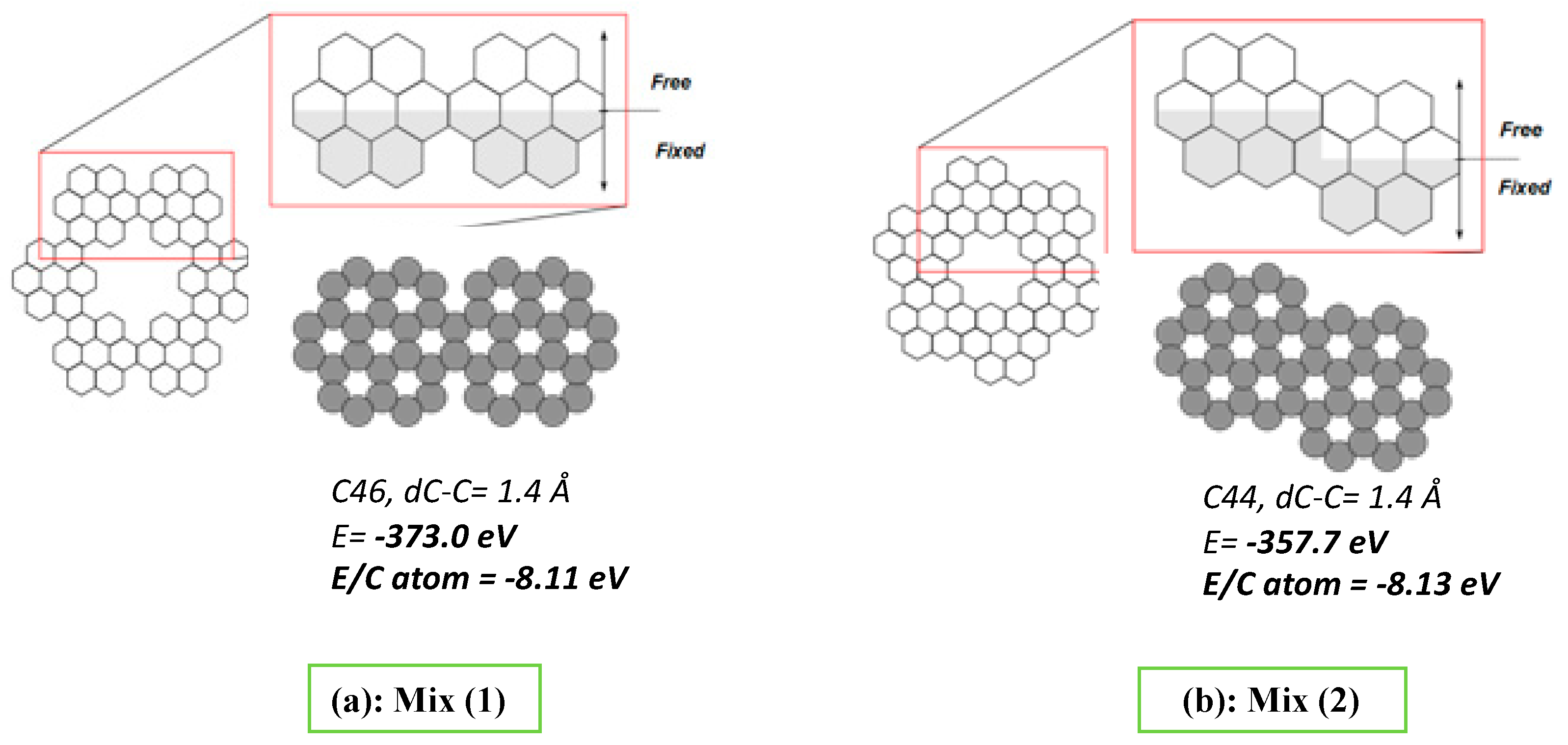
The theoretical investigation was performed for two benzenoid unit parts of two fractal architectures with order n = 2, named Mix (1) and Mix (2). Mix (1) with a symmetric arrangement includes 46 C atoms and Mix (2) includes 44 C atoms in a rotational symmetry system, Figure 2. Mix: corresponding to the mixed edges in each model.
Due to the fact that previous experimental etching was carried out under a bimodal atmosphere (oxidative and reductive) and the edges termination was not determined, the edges are free-terminated in the present simulations.
The geometry optimization was performed using BFGS quasi-Newton method [34,35] to generate the total energy of the systems Mix (1) and Mix (2). Taking into account the energy values (Figure 2), Mix (1) system exhibits the lowest total energy. The calculation of the energy per C atom in the two systems, however, exposes slightly lower energy for system Mix (2), i.e., −8.13 vs. −8.11 eV for Mix (1). The preferential rotary symmetry is somehow in agreement with the hierarchical multifractal nature of graphene characterized by this rotational symmetry as mentioned above [33], and observed experimental data for larger systems [23].
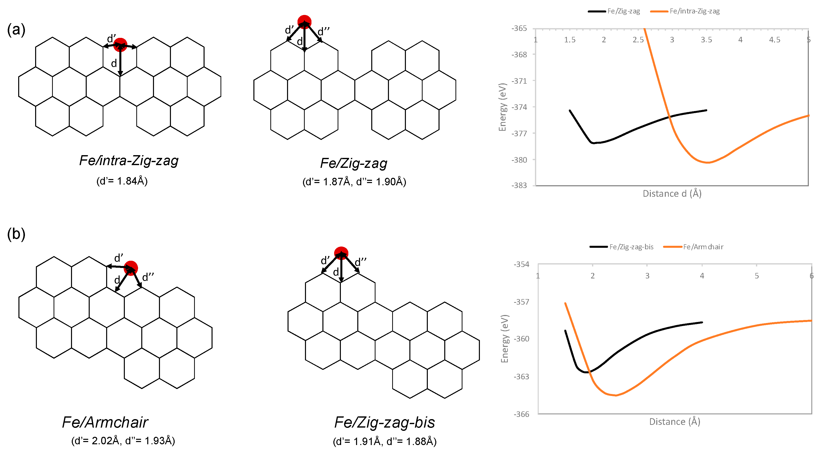
Four types of edge terminations in Mix (1) and Mix (2) were determined as Zig-zag, “intra-Zig-zag”, Armchair and Zig-zag-bis. Concerning the systems with iron, Fe-Mix (1) and Fe-Mix (2), two different positions of Fe atoms were considered for each C system displaying the distance between Fe and carbon atoms at the specific position, Figure 3. The energy curves are the functionals of distance d. The two systems with zigzag edge type in Mix (1) and Mix (2) called here Fe/Zig-zag and Fe/Zig-zag-bis show very similar behavior with the minimum energy at the same distance d, ~1.9 Å. In addition, according to symmetry reasons, the distances between the Fe atom and neighboring carbon atoms, d’ and d’’, vary slightly except Fe/intra-Zig-zag system.
The lowest total adsorption energy for an Fe atom at graphene edges was found in the Fe/Armchair configuration at the distance d = 2.4 Å. This is somehow in agreement with previous experimental work, where FLG flakes with fractal jagged edges decorated by Fe NPs obtained via catalytic cutting had mostly rotational symmetry. Concerning the energy gain, if compared to the isolated systems it decreases in the order: −6.2, −5.5, −3.9, −3.8 eV for Fe/intra-Zig-zag, Fe/Armchair, Fe/Zigzag, Fe/Zig-zag-bis, respectively (energy of Fe atom = −1.22 eV). The energy gain (Δ Eint) was computed as: Δ Eint (FeC) = E (FeC) − E (C) − E(Fe), with the considered chemical system in the parenthesis.
Likewise, Fe/intra-Zig-zag exhibits two minima of total energy due to the theoretically potential of two localizations of Fe atoms (inner and outer) as shown in Figure 4. The energy curve shows that the position 1 at 1.6 Å is, however, impossible, being much more energy demanding than the separated Fe, C systems.

4. Conclusions

The DFT calculations concerned the stability of Fe atoms at the edges of graphene structures representing small fractal models with perfect and rotational symmetry. The Fe free systems exhibit similar energy value per atom with a slight preference towards rotational symmetry. Four localizations of Fe atoms at the edges were determined depending on the edges’ geometry: Fe/intra-Zig-zag, Fe/Zig-zag, Fe/Armchair and Fe/Zig-zag-bis. The system with Fe atoms localized at armchair edges in rotational symmetry structures shows the lowest total energy. The data are useful for the further investigations of binding type in single metal atom catalyst-graphene support systems.

Author Contributions

Conceptualization, I.J.; methodology, L.A. and T.D.; software, T.D.; validation, T.D. and I.J.; formal analysis, L.A.; investigation, L.A., T.D. and I.J.; resources, I.J.; data curation, L.A. and T.D.; writing—original draft preparation, I.J.; writing—review and editing, I.J.; visualization, L.A. and I.J.; supervision, T.D. and I.J.; funding acquisition, I.J. All authors have read and agreed to the published version of the manuscript.

Funding

This research was funded by statutory support (CNRS, Unistra).

Institutional Review Board Statement

Not applicable.

Informed Consent Statement

Not applicable.

Data Availability Statement

Not applicable.

Acknowledgments

Hervé Bulou (IPCMS) is acknowledged for the brief discussion concerning calculation methods.

Conflicts of Interest

The authors declare no conflict of interest.

References

  1. Delplace, P.; Montambaux, G. WKB analysis of edge states in graphene in a strong magnetic field. Phys. Rev. B 2010, 82, 205412. [Google Scholar] [CrossRef] [Green Version]
  2. Park, C.; Yang, H.; Mayne, A.J.; Dujardin, G.; Seo, S.; Kuk, Y.; Ihm, J.; Kim, G. Formation of unconventional standing waves at graphene edges by valley mixing and pseudospin rotation. Proc. Natl. Acad. Sci. USA 2011, 108, 18622–18625. [Google Scholar] [CrossRef] [Green Version]
  3. Yamijala, S.S.R.K.C.; Bandyopadhyay, A.; Pati, S.K. Electronic properties of zigzag, armchair and their hybrid quantum dots of graphene and boron-nitride with and without substitution: A DFT study. Chem. Phys. Lett. 2014, 603, 28–32. [Google Scholar] [CrossRef] [Green Version]
  4. Sk, M.A.; Huang, L.; Chen, P.; Lim, K.H. Controlling armchair and zigzag edges in oxidative cutting of graphene. J. Mater. Chem. C 2016, 4, 6539–6545. [Google Scholar] [CrossRef]
  5. Klein, D.J. Graphitic polymer strips with edge states. Chem. Phys. Lett. 1994, 217, 261–265. [Google Scholar] [CrossRef]
  6. He, K.; Robertson, A.W.; Lee, S.; Yoon, E.; Lee, G.-D.; Warner, J.-H. Extended Klein Edges in Graphene. ACS Nano 2014, 8, 12272–12279. [Google Scholar] [CrossRef]
  7. Wagner, P.; Ivanovskaya, V.V.; Melle-Franco, M.; Humbert, B.; Adjizian, J.-J.; Briddon, P.R.; Ewels, C.P. Stable hydrogenated graphene edge types: Normal and reconstructed Klein edges. Phys. Rev. B 2013, 88, 094106. [Google Scholar] [CrossRef] [Green Version]
  8. Zhang, X.; Yazyev, O.V.; Feng, J.; Xie, L.; Tao, C.; Chen, Y.-C.; Jiao, L.; Pedramrazi, Z.; Zettl, A.; Louie, S.G.; et al. Experimentally Engineering the Edge Termination of Graphene Nanoribbons. ACS Nano 2013, 7, 198–202. [Google Scholar] [CrossRef] [PubMed] [Green Version]
  9. He, K.; Lee, G.D.; Robertson, A.W.; Yoon, E.; Warner, J.H. Hydrogen-free graphene edges. Nat. Commun. 2014, 5, 3040. [Google Scholar] [CrossRef] [Green Version]
  10. Chełmecka, E.; Pasterny, K.; Kupka, T.; Stobiński, L. DFT studies of COOH tip-functionalized zigzag and armchair single wall carbon nanotubes. J. Mol. Model. 2012, 18, 2241–2246. [Google Scholar] [CrossRef] [PubMed]
  11. Chełmecka, E.; Pasterny, K.; Kupka, T.; Stobiński, L. OH-functionalized open-ended armchair single-wall carbon nanotubes (SWCNT) studied by density functional theory. J. Mol. Model. 2012, 18, 1463–1472. [Google Scholar] [CrossRef] [PubMed] [Green Version]
  12. Gusynin, V.P.; Miransky, V.A.; Sharapov, S.G.; Shovkovy, I.A. Edge states, mass and spin gaps, and quantum Hall effect in graphene. Phys. Rev. B 2008, 77, 205409. [Google Scholar] [CrossRef] [Green Version]
  13. Santana, A.; Popov, A.M.; Bichoutskaia, E. Stability and dynamics of vacancy in graphene flakes: Edge effects. Chem. Phys. Lett. 2013, 557, 80–87. [Google Scholar] [CrossRef] [Green Version]
  14. Terrones, M.; Botello-Méndez, A.R.; Campos-Delgado, J.; López-Urías, F.; Vega-Cantú, Y.I.; Rodríguez-Macías, F.J.; Elías, A.L.; Muñoz-Sandoval, E.; Cano-Márquez, A.G.; Charlier, J.-C.; et al. Graphene and graphite nanoribbons: Morphology, properties, synthesis, defects and applications. Nano Today 2010, 5, 351–372. [Google Scholar] [CrossRef]
  15. Yang, X.; Dou, X.; Rouhanipour, A.; Zhi, L.; Räder, H.J.; Müllen, K. Two-Dimensional Graphene Nanoribbons. J. Am. Chem. Soc. 2008, 130, 4216–4217. [Google Scholar] [CrossRef]
  16. Dössel, L.; Gherghel, L.; Feng, X.; Müllen, K. Graphene Nanoribbons by Chemists: Nanometer-Sized, Soluble, and Defect-Free. Angew. Chem. Int. Ed. 2011, 50, 2540–2543. [Google Scholar] [CrossRef]
  17. Ruffieux, P.; Wang, S.; Yang, B.; Sánchez-Sánchez, C.; Liu, J.; Dienel, T.; Talirz, L.; Shinde, P.; Pognedoli, C.A.; Passerone, D.; et al. On-surface synthesis of graphene nanoribbons with zigzag edge topology. Nature 2016, 531, 489–492. [Google Scholar] [CrossRef] [Green Version]
  18. Feng, J.; Li, W.; Qian, X.; Qi, J.; Qi, L.; Li, J. Patterning of graphene. Nanoscale 2012, 4, 4883–4899. [Google Scholar] [CrossRef]
  19. Schäffel, F.; Warner, J.H.; Bachmatiuk, A.; Rellinghaus, B.; Büchner, B.; Schultz, L.; Rümmeli, M.H. Shedding Light on the Crystallographic Etching of Multi-Layer Graphene at the Atomic Scale. Nano Res. 2009, 2, 695–705. [Google Scholar] [CrossRef] [Green Version]
  20. Baaziz, W.; Melinte, G.; Ersen, O.; Pham-Huu, C.; Janowska, I. Effect of nitriding/nanostructuration of few layer graphene supported iron-based particles; Catalyst in graphene etching and carbon nanofilament growth. PhysChemChemPhys 2014, 16, 15988–15993. [Google Scholar] [CrossRef]
  21. Geng, D.; Wu, B.; Guo, Y.; Luo, B.; Xue, Y.; Chen, J.; Yu, G.; Liu, Y. Fractal Etching of Graphene. J. Am. Chem. Soc. 2013, 135, 6431–6434. [Google Scholar] [CrossRef]
  22. Geng, D.; Wang, H.; Wan, Y.; Xu, Z.; Luo, B.; Xu, J.; Yu, G. Direct Top-Down Fabrication of Large-Area Graphene Arrays by an In Situ Etching Method. Adv. Mater. 2015, 27, 4195–4199. [Google Scholar] [CrossRef]
  23. Janowska, I.; Lafjah, M.; Papaefthymiou, V.; Pronkin, S.; Ulhaq-Bouillet, C. Edges fractal approach in graphene-Defects density gain. Carbon 2017, 123, 395–401. [Google Scholar] [CrossRef]
  24. Banhart, F.; Kotakoski, J.; Krasheninnikov, A.V. Structural Defects in Graphene. ACS Nano 2010, 5, 26–41. [Google Scholar] [CrossRef] [Green Version]
  25. Su, D.S.; Perathoner, S.; Centi, G. Nanocarbons for the Development of Advanced Catalysts. Chem. Rev. 2012, 113, 5782–5816. [Google Scholar] [CrossRef] [PubMed]
  26. Luo, G.; Liu, L.; Zhang, J.; Li, G.; Wang, B.; Zhao, J. Hole Defects and Nitrogen Doping in Graphene: Implication for Supercapacitor Applications. ACS Appl. Mater. Interfaces 2013, 5, 11184–11193. [Google Scholar] [CrossRef] [PubMed]
  27. Yuan, W.; Zhou, Y.; Li, Y.; Li, C.; Peng, H.; Zhang, J.; Liu, Z.; Dai, L.; Shi, G. The edge- and basal-plane-specific electrochemistry of a single-layer graphene sheet. Sci. Rep. 2013, 3, 2248. [Google Scholar] [CrossRef] [Green Version]
  28. Shen, A.; Zou, Y.; Wang, Q.; Dryfe, R.A.W.; Huang, X.; Dou, S.; Dai, L.; Wang, S. Oxygen Reduction Reaction in a Droplet on Graphite: Direct Evidence that the Edge Is More Active than the Basal Plane. Angew. Chem. Int. Ed. 2014, 53, 10804–10808. [Google Scholar] [CrossRef]
  29. Ricciardella, F.; Vollebregt, S.; Polichetti, T.; Miscuglio, M.; Alfano, B.; Miglietta, M.L.; Massera, E.; Di Francia, G.; Sarro, P.M. Effects of Graphene Defects on Gas Sensing Properties Towards NO2 Detection. Nanoscale 2017, 9, 6085–6093. [Google Scholar] [CrossRef] [Green Version]
  30. Janowska, I.; Moldovan, M.-S.; Ersen, O.; Bulou, H.; Chizari, K.; Ledoux, M.-J.; Pham-Huu, C. High-temperature stability of platinum nanoparticles on few-layer graphene investigated by in-situ HR-TEM. Nano Res. 2011, 4, 511–521. [Google Scholar] [CrossRef]
  31. Serp, P.; Pham, M.D. Supported Metal Single Atom Catalysis; Wiley-VCH GmbH: Weinheim, Germany, 2022. [Google Scholar]
  32. Zhao, J.; Deng, Q.; Avdoshenko, S.M.; Fu, L.; Eckert, J.; Rümmeli, M.H. Direct in situ observations of single Fe atom catalytic processes and anomalous diffusion at graphene edges. Proc. Natl. Acad. Sci. USA 2014, 111, 15641–15646. [Google Scholar] [CrossRef] [PubMed] [Green Version]
  33. Zhang, T.; Ding, K. Hierarchical fractal structure of perfect single-layer graphene. Front. Mech. Eng. 2013, 8, 371–382. [Google Scholar] [CrossRef]
  34. Dai, Y.-H. A perfect example for the BFGS method. Math. Program. Ser. A 2013, 138, 501–530. [Google Scholar] [CrossRef]
  35. Dennis, J.E.; Schnabel, R.B. Numerical Methods for Unconstrained Optimization and Nonlinear Equations; Society for Industrial and Applied Mathematics: Philadelphia, PA, USA, 1996. [Google Scholar]
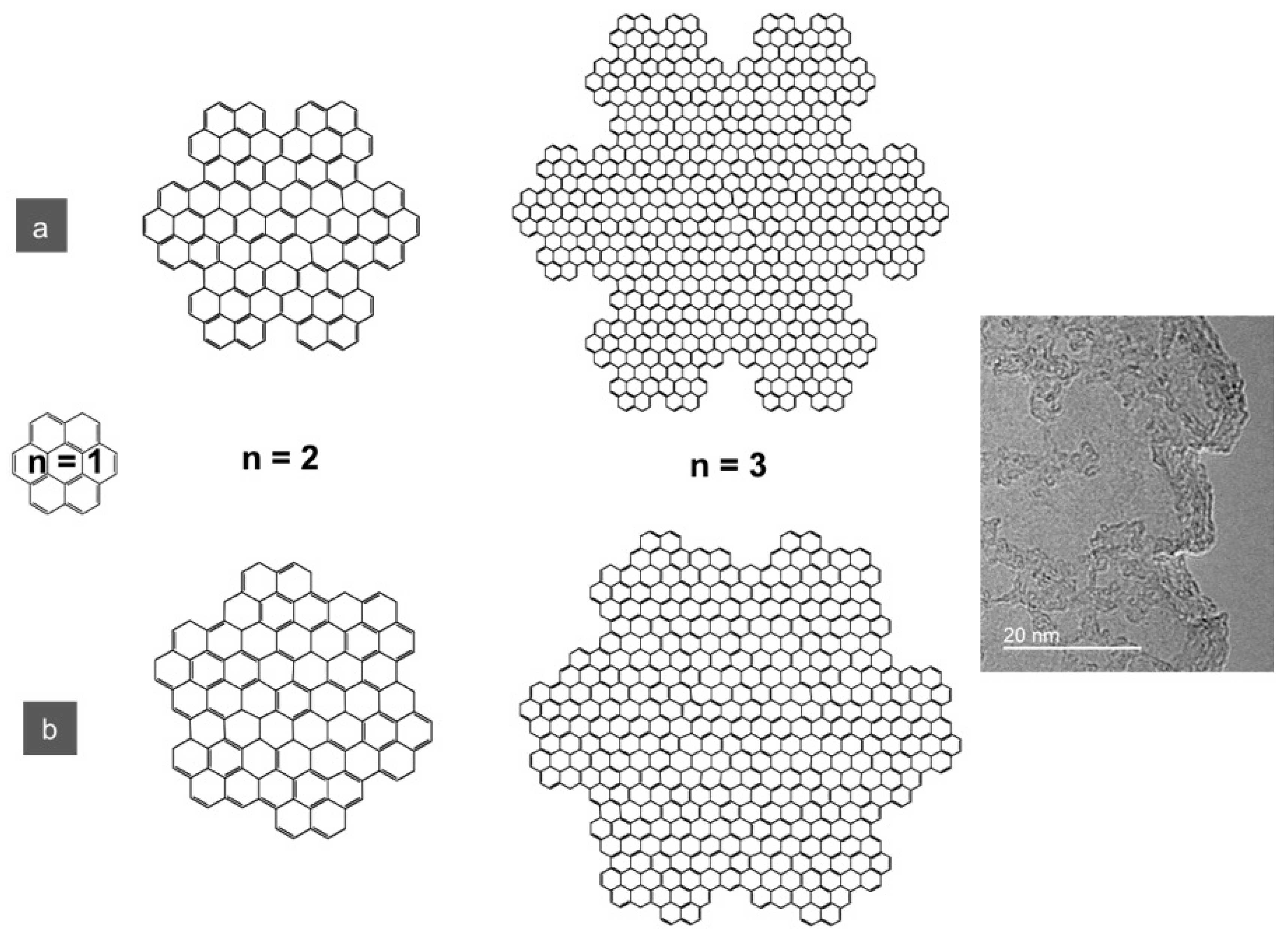
Figure 1. The models of graphene formed from coronene growing in a fractal manner with two symmetries: (a) symmetric and (b) rotational symmetry (19.1°) [23] (The models are drawn by ChemDraw; all C atoms have sp2 hybridization). The TEM micrograph shows jaggy non-integer dimension graphene edges with rotational symmetry.
Chemengineering 06 00079 g001
Figure 2. Schemes of the two systems studied using DFT method: (a) Mix (1) as a mixture of Zig-zag and intra-Zig-zag edges with 46 atoms of carbon, and (b) Mix (2) as a mixture of Zig-zag and Armchair with 44 atoms of carbon. The free and fixed atoms were configurated as shown via grey coloring. The total energy and energy per C atom calculated for two graphene models.
Chemengineering 06 00079 g002
Figure 3. Schema of four systems including Fe-M(1) (a) and Fe-M(2) (b) with different positions of the Fe atoms studied with DFT method and the corresponding energy variation curves.
Chemengineering 06 00079 g003
Figure 4. Schema of Fe/intra-Zig-zag system with different d distance. (d1, d2) Energy-distance d curve with two minima in the system.
Chemengineering 06 00079 g004
Publisher’s Note: MDPI stays neutral with regard to jurisdictional claims in published maps and institutional affiliations.