Article

Development of Continuous Gas Generation Method for Hydrogen Chloride Using Azeotropic Hydrochloric Acid System

1
Gastec Corporation, 8-8-6 Fukayanaka, Ayase 252-1195, Kanagawa, Japan
2
Department of Chemistry, School of Science, Tokai University, 4-1-1 Kitakaname, Hiratsuka 259-1292, Kanagawa, Japan
*
Author to whom correspondence should be addressed.
ChemEngineering 2022, 6(1), 12; https://doi.org/10.3390/chemengineering6010012
Submission received: 24 December 2021 / Revised: 12 January 2022 / Accepted: 21 January 2022 / Published: 1 February 2022
(This article belongs to the Special Issue Chemical Engineering and Multidisciplinary)

Abstract

:
Standard gases are often prepared using high-pressure gas cylinders. However, it is difficult to accurately prepare a known concentration of hydrogen chloride (HCl) gas using this method because HCl is highly corrosive and adsorptive. In this study, a simple method for the continuous generation of HCl gas was developed using a diffusion tube containing hydrochloric acid and a nitrogen carrier gas. The concentration of HCl produced from this system was almost unstable, but constant gas generation was realized for several hours when azeotropic hydrochloric acid (20.6% HCl in water) and a temperature near the azeotropic point (108.5 °C) were used, resulting in the generation of 103.6 ppm (mean, n = 5) of HCl gas with a relative standard deviation (RSD) of 2.34%. In this case, the percentage of HCl present in the entire gas mixture of HCl and water vapor was 22.5%, which is almost equivalent to the HCl content in the azeotropic hydrochloric acid (20.6%). The HCl concentration could also be controlled by changing the flow rate of the carrier gas. This work demonstrates a simple technique based on the diffusion theory that allows for the constant, controllable generation of a known concentration of HCl gas using an azeotropic hydrochloric acid system.

Graphical Abstract

1. Introduction

Hydrogen chloride (HCl) is a pungent, highly corrosive, and toxic substance [1]. It dissolves easily in water and exists in gaseous or aerosol forms in the atmosphere [2]. Gaseous HCl is directly released into the atmosphere from volcanos [3], waste incineration [4], coal combustion [4,5], biomass burning [6], and manufacturing processes [4]; it is also produced from the sea-salt dechlorination of the marine boundary layer [7]. HCl in the atmosphere is the main cause of the stratospheric chlorine reservoir [8] and triggers a series of chemical reactions that cause ozone depletion [9]. In many industries, HCl is often used in an aqueous form as hydrochloric acid to produce materials such as fertilizers, textiles, rubbers, and electronics [10]. The concentration of gaseous HCl used in such workplaces is often on the scale of ppm [11,12]; this is dangerous because when HCl gas is inhaled and contacts moisture in the upper respiratory tract it rapidly dissociates [13]. Exposure to HCl is also responsible for chronic gastritis, dental discoloration, and erosion (from prolonged exposure) [14]. Prolonged exposure to trace amounts of gaseous HCl also affects products such as semiconductors, electrical appliances, and museum exhibits due to its highly corrosive properties [15]. Therefore, the monitoring of gaseous HCl both in indoor and outdoor environments is strongly required, and removal of HCl is necessary to prevent its direct, negative influence on human health and consumer products. A standard gas containing trace amounts of HCl (below the ppm level) is typically required for the calibration of instruments that are used to accurately monitor HCl. Such a standard gas is also applicable as a test gas to evaluate the performance of materials designed for HCl removal and/or the durability of materials exposed to HCl.
Standard gas is usually prepared using a high-pressure gas cylinder [16,17]. However, this method is not suitable for preparing HCl because this gas is highly absorptive and corrosive; HCl molecules could easily adhere to the cylinder wall, which would decrease the overall concentration of HCl. Meanwhile, dynamic generation, permeation [18,19,20], and diffusion [21,22,23] methods allow for the accurate preparation of HCl gas. Several studies regarding the dynamic generation of HCl were conducted using the permeation [24,25,26], and diffusion [25] methods with hydrochloric acid. In these methods, HCl gas is evaporated from hydrochloric acid in a permeation tube or diffusion tube kept at a constant temperature. The standard gas is then continuously prepared by mixing the evaporated gas with a specific amount of carrier gas, such as air, nitrogen, or helium, at a constant rate, allowing for HCl gas to be prepared in concentrations ranging from ppb to ppm. Since hydrochloric acid is a binary compound, HCl gas is obtained as a mixture with water vapor. Therefore, the use of an azeotropic hydrochloric acid solution (approximately 20% (w/w)) is preferable for the generation of HCl/water-vapor gas mixtures with constant compositions over time. However, a previous study by Norton et al. [25] reported that the concentration of HCl emitted from a permeation tube did not agree with the value provided by the manufacturer, even when using an azeotropic hydrochloric acid solution (approximately 20% (w/w)).
The present study aimed to develop a diffusion tube preparation method for standard HCl gas based on the azeotrope theory. The diffusion tube method simply employs the molecular diffusion process of a target gas in a tube and subsequent dilution with a carrier gas; the concentration of the prepared gas tends to become constant within a relatively short time, only a few hours after initiation. This is a much faster rate than that of the permeation tube method. In the work reported herein, gaseous HCl was prepared using azeotropic hydrochloric acid and other concentrations of hydrochloric acid at several temperatures, including the azeotropic point. Time courses monitoring the concentration and composition of the prepared HCl gas were also conducted. The influence of the flow rate of the carrier gas on the HCl concentration was also investigated. The developed method employing an azeotropic system based on the diffusion theory was found to provide the constant, controllable generation of HCl gas.

2. Materials and Methods

2.1. Reagents

All reagents used in this experiment were of analytical grade. Aqueous reagent solutions were prepared using deionized water.
Azeotropic hydrochloric acid (Super Special Grade, Fujifilm Wako Pure Chemical Corp., Osaka, Japan) with a concentration of 20.6% (certified by the manufacturer) and non-azeotropic hydrochloric acid (Super Special Grade, Fujifilm Wako Pure Chemical Corp., Osaka, Japan) with a concentration of 35.9% (certified by the manufacturer) were used as the sources of gaseous HCl.
A sodium chloride solution suitable for volumetric analysis (0.05 M, Fujifilm Wako Pure Chemical Corp., Osaka, Japan) was used as a chloride ion standard for the determination of HCl. Working standard solutions of chloride ions were prepared by diluting the standard sodium chloride solution to the desired concentration with deionized water. Mercury(II) thiocyanate (Wako Special Grade), perchloric acid (guaranteed reagent), and methanol (guaranteed reagent) were purchased from Fujifilm Wako Pure Chemical Corp. (Osaka, Japan). Ammonium iron(III) sulfate 12-water (guaranteed reagent) was purchased from Junsei Chemical Co., Ltd. (Tokyo, Japan). A 0.50% (w/w) mercury(II) thiocyanate solution was prepared by dissolving mercury(II) thiocyanate in methanol, and 2.2% (w/w) ammonium iron(III) sulfate solution was prepared in 52% (w/w) aqueous perchloric acid. Both solutions were used for the determination of HCl.

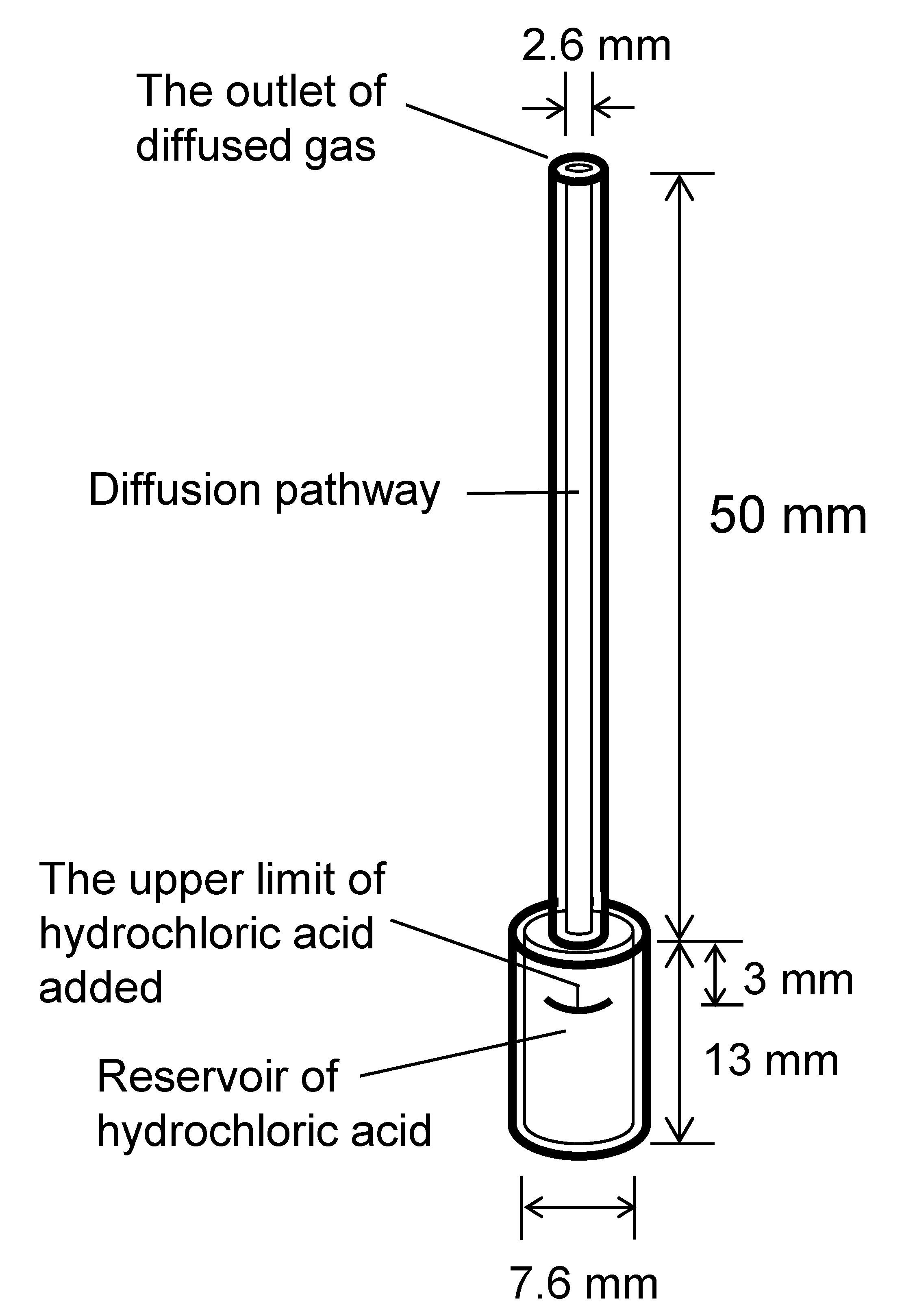
2.2. Preparation of Diffusion Materials

The diffusion device comprised a conventional diffusion tube made of Pyrex® glass (D-02, Gastec Corp., Kanagawa, Japan) that contained a reservoir (0.6 mL volume, 7.6 mm inner diameter, and 13 mm length) for pooling the source reagent; the gas diffusion pathway had an inner diameter of 2.6 mm and a length of 50 mm. Three gaseous HCl sources were prepared from different concentrations of hydrochloric acid and are as follows: (a) a 20.6% (w/w) azeotropic solution, (b) a 14.8% (w/w) solution prepared by diluting the azeotropic solution with deionized water, and (c) a 26.3% (w/w) solution prepared by diluting 35.9% (w/w) hydrochloric acid with deionized water. Three diffusion tubes were used, to which approximately 0.45 g of solution (a), solution (b), or solution (c) was added; the upper surfaces of each solution were 3 mm from the top of the reservoir of their respective tubes. Figure 1 shows an outlined diagram of the diffusion tubes.

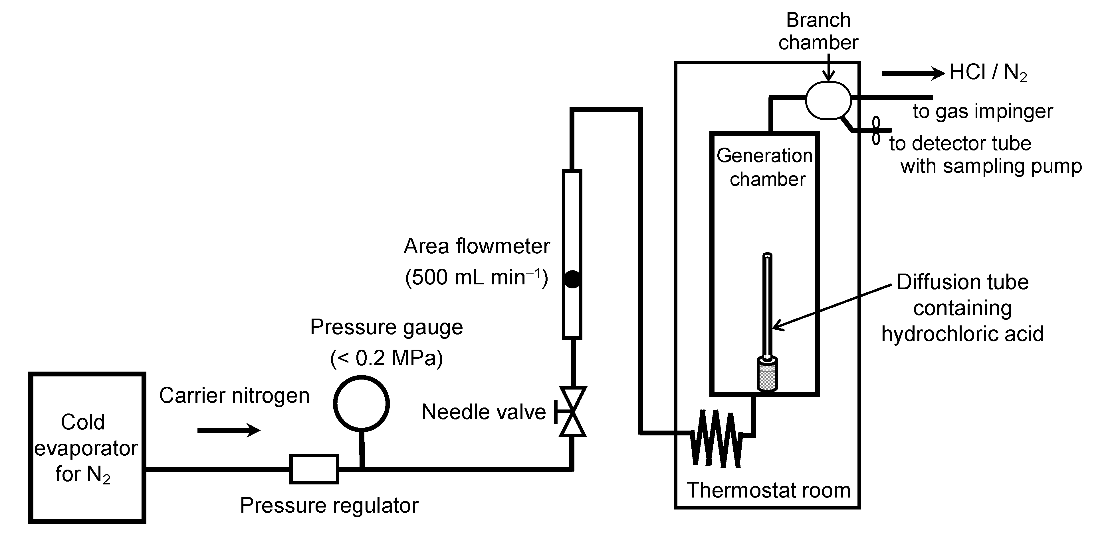
2.3. System for HCl Gas Generation

A schematic of the apparatus used for the continuous generation of HCl gas is shown in Figure 2. The generator system was composed of a glass chamber, thermostat, diffusion tube, flow meter, flow-regulated needle valve, pressure gauge for the carrier gas, and a two-way branch chamber. A diffusion tube containing a hydrochloric acid solution (a–c) was placed at the bottom of the chamber. The diffusion chamber and the two-way branch chamber were placed in the thermostat (±0.1 °C, PU-1K PH, ESPEC Corp., Osaka, Japan) and kept at a constant temperature of 70.0, 90.0, or 108.5 °C. Nitrogen gas from a cold evaporator (Air Liquide Japan Ltd., Tokyo, Japan) was used as the carrier gas for the dilution of the generated gas and was continuously introduced into the diffusion chamber from the bottom, flowing upward, after it was heated with the thermostat. The flow rate of the nitrogen gas was controlled at a constant rate using a flow meter with a precision needle valve (RK1500, KOFLOC Corp., Kyoto, Japan) that exhibited a precision of ±2% relative to the full-scale valve.

2.4. Measurements of Gaseous HCl Produced from the Generation System

The HCl concentration obtained from the azeotropic solution (solution (a)) that was heated at 108.5 °C (nearly the azeotropic point) was determined with mercury(II) thiocyanate spectrophotometry [27]. The nitrogen gas flow rate was maintained at 500 mL min−1. A 30 mL gas impinger (G-1, Sibata Scientific Technology Ltd., Tokyo, Japan), which housed 20 mL of deionized water as an absorbing solution, was used for the collection of HCl. The gas impinger was placed outside the thermostat and was kept at an ambient temperature of approximately 20 °C. The effluent gas from the branch chamber was directly introduced to the gas impinger as one side of the outlet of the branch was closed, and the target gas was collected by bubbling for 2 min. After collection, 2 mL of the ammonium iron(III) sulfate solution, 1 mL of the mercury(II) thiocyanate solution, and 10 mL of methanol were added to 10 mL of the absorbent. The mixture was left for 5 min at room temperature and then its absorbance was measured at 460 nm with a UV spectrophotometer (UVmini-1240, SHIMADZU Corp., Kyoto, Japan). The background concentrations of HCl were determined by collecting the carrier gas.
The gaseous HCl concentration was also determined using the detector tube method; this was carried out to cross-check the values obtained via mercury(II) thiocyanate spectrophotometry measurements. The gas inlet of a detector tube for hydrogen chloride (14 M, Gastec Corp., Kanagawa, Japan) was placed outside of the thermostat and connected to the gas flow path from one side of the outlet of the branch chamber; the other outlet of the chamber was open and a fixed amount of the gas was aspirated to the detector tube by a sampling pump (GV-100, Gastec Corp., Kanagawa, Japan).
The detector tube method (14 M or 14 L, Gastec Corp., Kanagawa, Japan) was also used to determine the HCl gas concentrations obtained from the experiments that employed the other conditions (i.e., those that used the diffusion tubes containing the other hydrochloric acid solutions ((b) and (c)) and temperatures of 70.0, 90.0, or 108.5 °C, and the azeotropic solution (a) and temperatures of 70.0 or 90.0 °C).

2.5. Measuring the Changes in the Masses of the Diffusion Materials

To estimate the content of HCl gas in the entire gas mixture diffused from the tube, the mass changes in the diffusion tube during the generation, which corresponds to the sum of masses of HCl and water diffused from the tube during the period, were measured. The mass of the tube was weighed before and after gas generation using an electronic balance (XS205, Mettler Toledo International Inc., Greifensee, Switzerland), and the difference between them was obtained. After gas generation, the diffusion tube was removed from the diffusion chamber and left in the balance room for 30 min to determine its weight.

3. Results and Discussion

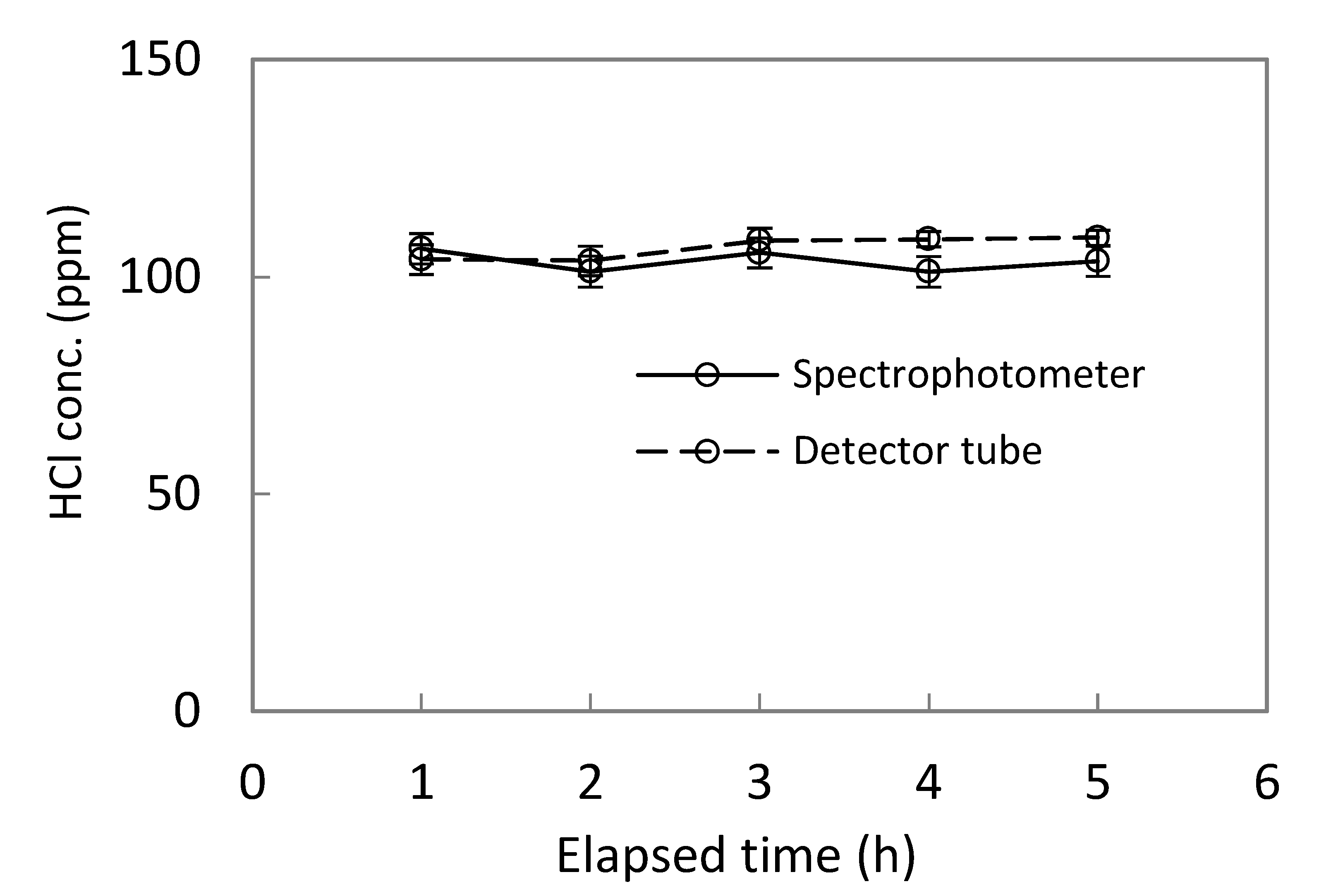
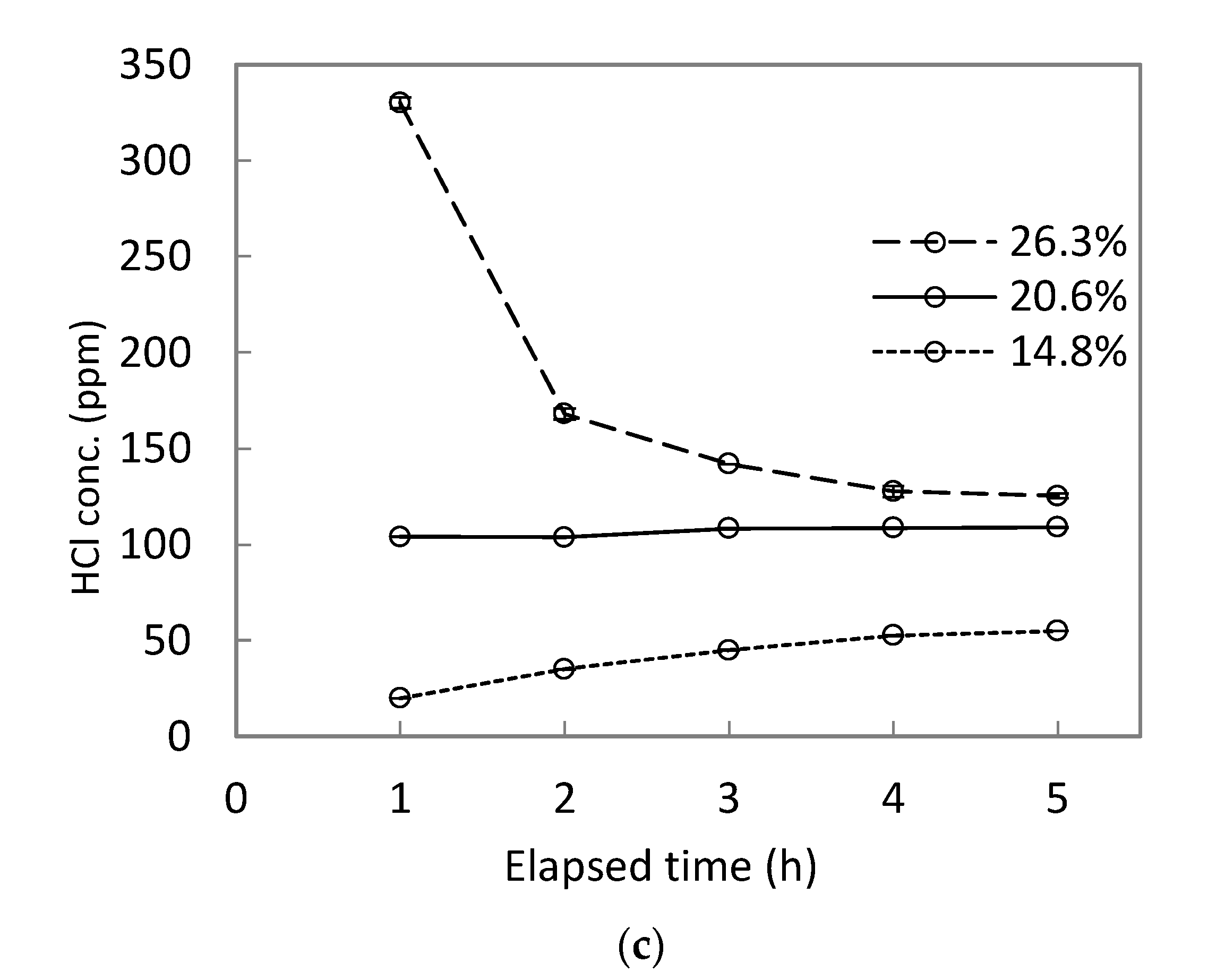
3.1. Stability of Gaseous HCl

HCl gas was generated for approximately 5 h using a generation system with azeotropic hydrochloric acid at 108.5 °C (nearly the azeotropic point), and its concentration was measured every hour with both mercury(II) thiocyanate spectrophotometry and the detector tube method. The background concentration of HCl in the carrier gas was less than 0.10 ppm. Figure 3 shows the time courses that were conducted with both analyses to monitor the concentration of gaseous HCl that was obtained when using azeotropic hydrochloric acid (solution (a)) at 108.5 °C. The mean HCl concentration determined from five measurements taken during the course of gas generation was determined by spectrophotometry to be 103.6 ppm (v/v; converted to the value at 20 °C) (2.35% of relative standard deviation (RSD)) and by the detector tube method to be 106.7 ppm (v/v at 20 °C) (2.49% RSD). The variation in the HCl concentrations determined by both analyses was less than 3%. The five spectrophotometry measurements obtained during gas generation agreed with each other within the expanded uncertainty that was below 3.58% (coverage factor of k = 2). These results indicate that HCl gas could be constantly generated for more than 4 h after the equilibrium of diffusion was achieved, which occurred within 1 h of the tube being introduced into the apparatus. The known HCl gas concentration could be provided when using the azeotrope solution (solution (a)) at 108.5 °C. The values determined by spectrophotometry and the detector tube method only differed by 2.99%, demonstrating that either method could be used to properly conduct the measurements.
Figure 4 shows the time courses where the HCl concentration was measured with the detector tube method under all conditions of varying temperature and hydrochloric acid concentration, as described in the experimental section. The variations (RSD) in the five measurement points for 14.8% hydrochloric acid were 12.5%, 13.0%, and 34.6% at 70.0, 90.0, and 108.5 °C, respectively, and those for 26.3% hydrochloric acid were 3.2%, 14.8%, and 48.3% at 70.0, 90.0, and 108.5 °C, respectively. The variations (RSD) in the measurements for the azeotropic solution were 20.6% and 9.7% at 70.0 °C and 90.0 °C, respectively. Unstable HCl gas generation was observed at all temperatures when using non-azeotropic hydrochloric acid; it was also observed for the azeotropic solution at temperatures other than the azeotropic point. In these cases, the time courses for monitoring HCl concentration were not uniform. Therefore, constant HCl gas generation could not be performed under all conditions except when employing the azeotrope at a temperature near the azeotropic point.

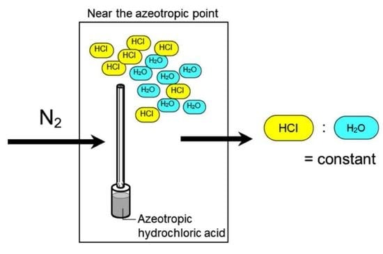
3.2. Evaluation of the Azeotrope System for HCl Gas Generation

To evaluate the diffusion with the azeotrope system for HCl, the content of gaseous HCl in the entire HCl/water-vapor gas mixture that was diffused from the tube was estimated by comparing the amount of HCl diffused from the tube to the total amount of gases diffused from the tube. First, the rate of mass loss (Drm, µg min−1) of the diffusion tube was determined by weighing the tube before and after gas generation using Equation (1) [17,28].
D r m = M 2 M 1 t
where t is the period before and after generation (min) and M1 and M2 are the masses of the diffusion tube (µg) before and after gas generation.
Next, the rate of HCl diffusion (DrHCl, µg min−1), which is the mass of diffused HCl per unit of time, was calculated using the measured concentration of gaseous HCl and the carrier gas flow rate (Equation (2)).
D r HCl = C × F × M 24.04 × 10 3
where C is the concentration of gaseous HCl determined by the detector tube method (ppm), F is the flow rate of the carrier gas (mL min−1), and M is molar mass of HCl (g mol−1).
Finally, the ratio of DrHCl to Drm was determined. Table 1 shows the rate of mass loss for the tubes, the rate of HCl diffusion at the first measurement point (1 h after gas generation began), and the percentage of the HCl diffusion rate in the mass loss rate of the tube. The value of DrHCl was 0.48 to 261.57 µg min−1. Aoyagi et al. [28] reported that the diffusion rate of formaldehyde and methanol was observed in the range of 0.2 to 8 µg min−1, that is equivalent level to that of HCl in the present study, showing that these values of DrHCl are appropriate.
The percentage of gaseous HCl in the total amount of gas diffused from the tube was significantly different for each hydrochloric acid solution under all experimental conditions, except when employing the azeotrope at 108.5 °C. In this case, the HCl diffusion based on the azeotropic hydrochloric acid system was not performed.
Meanwhile, the azeotrope at 108.5 °C produced HCl gas with a percentage of 22.5% in the entire gas mixture of HCl and water diffused from the diffusion tube, which is almost equivalent to the HCl content of the azeotrope solution (20.6%). In fact, the concentration of gaseous HCl generated under this condition remained constant. This implies that considerable HCl diffusion from the azeotrope occurred at 108.5 °C. The estimated HCl percentage obtained using the azeotrope at 108.5 °C was slightly higher than the HCl content of the azeotrope solution. This is probably due to the underestimation of the total amount of gases (HCl and water) diffused from the tube. The value of t in Equation (1) includes both the time it took for the target temperature of 108.5 °C to be reached after placing the tube in the chamber and the time it took to cool the tube back to ambient temperature once it was removed from the chamber; the mass loss during these periods was lower than that during the diffusion at 108.5 °C. As a result, the calculated mass loss rate would be lower than the actual mass loss rate, which would result in the percentage of gaseous HCl being overestimated.
In contrast with our results above, Norton et al. [25] employed an azeotrope of HCl under a condition except the azeotopic point. This is probably the main cause of undesired generation. Conclusively, the diffusion of the azeotrope at the azeotropic point is strongly required for the precise preparation of HCl.

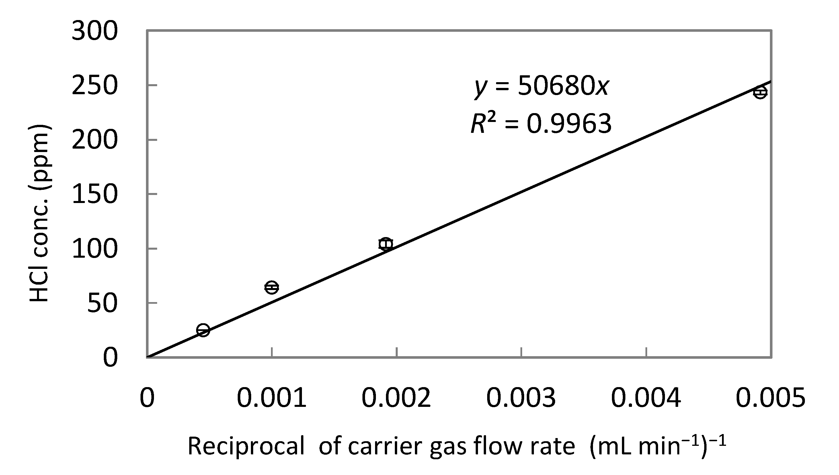
3.3. Preparation of Gaseous HCl with Different Carrier Gas Flow Rates

All of the present examinations of HCl generation mentioned above were conducted at the carrier gas flow rate of 500 mL min−1. To evaluate whether the gas concentration correlates with changes in the carrier gas flow rate, the measurement of HCl was conducted using the detector tube method under varying carrier gas flow rates (from 200 to 2200 mL min−1). The relationship is expressed in Equation (3), which is derived from Equation (2) assuming the diffused HCl was correlatively diluted by the carrier gas. In this case, the relationship between the concentration of gaseous HCl and the reciprocal of the carrier gas flow rate gave a straight line without an intercept when plotted.
C = D r HCl × 24.04 × 10 3 M × 1 F
These relationships are shown in Figure 5. The concentration of gaseous HCl and the reciprocal of the carrier gas flow rate were found to follow a distinctly straight line with an intercept of zero. This allows for the term on the right side of Equation (3), except the “1/F” term, to be regarded as a constant, which demonstrates that the rate of HCl diffusion is not dependent on the carrier gas flow rate. This result indicates that the HCl concentration could be controlled by adjusting the carrier gas flow rate, allowing for the constant generation of a desired concentration of HCl gas.

4. Conclusions

A simple gas preparation method for HCl was developed using a diffusion tube containing hydrochloric acid and nitrogen as the carrier gas. The constant generation of HCl gas was observed for several hours when using an azeotropic hydrochloric acid at a temperature (108.5 °C) that was very close to the azeotropic point. Meanwhile, the HCl concentration was not stable when other combinations of temperature and solution concentration were used. In the case of constant gas generation, the percentage of gaseous HCl present in the entire HCl/water-vapor gas mixture was close to that present in the azeotropic solution. These results indicate that constant HCl gas generation can be successfully performed using an azeotrope system. Due to the independence of the HCl gas diffusion rate from the carrier gas flow rate, the concentration of the generated HCl gas could be controlled by adjusting the carrier gas flow rate; therefore, this technique can easily provide known concentrations of HCl gas.

Author Contributions

Conceptualization, R.A. and Y.S.; methodology, R.A.; resources, Y.K. and K.M.; supervision, Y.S. All authors have read and agreed to the published version of the manuscript.

Funding

This research received no external funding.

Institutional Review Board Statement

Not applicable.

Informed Consent Statement

Not applicable.

Data Availability Statement

The data presented in this study are available within the article (tables and figures). The data presented in this study are available on request from the corresponding author.

Conflicts of Interest

The authors declare no conflict of interest.

References

  1. Perry, W.G.; Smith, F.A.; Kent, M.B. The halogens. In Patty’s Industrial Hygiene and Toxicology, 4th ed.; Clayton, G.D., Clayton, F.E., Eds.; John Wiley & Sons: New York, NY, USA, 1994; Volume 2, pp. 4487–4490. [Google Scholar]
  2. Sebacher, D.I.; Bendura, R.J.; Wornom, D.E. Hydrochloric acid aerosol and gaseous hydrogen chloride partitioning in a cloud contaminated by solid rocket exhaust. Atmos. Environ. 1980, 14, 543–547. [Google Scholar] [CrossRef]
  3. Hisham, M.W.M.; Bommaraju, T.V. Hydrogen chloride. In Kirk-Othmer Encyclopedia of Chemical Technology, 4th ed.; Kroschwitz, J.I., Howe-Grant, M., Eds.; John Wiley & Sons: New York, NY, USA, 1995; Volume 13, p. 894925. [Google Scholar]
  4. McCulloch, A.; Aucott, M.L.; Benkovitz, C.M.; Graedel, T.E.; Kleiman, G.; Midgley, P.M.; Li, Y.-F. Global emissions of hydrogen chloride and chloromethane from coal combustion, incineration and industrial activities: Reactive Chlorine Emissions Inventory. J. Geophys. Res. 1999, 104, 8391–8403. [Google Scholar] [CrossRef] [Green Version]
  5. Keene, W.C.; Khalil, M.A.K.; Erickson, D.J., III; McCulloch, A.; Graedel, T.E.; Loberr, J.M.; Aucott, M.L.; Gong, S.L.; Harper, D.B.; Kleiman, G.; et al. Composite global emissions of reactive chlorine from anthropogenic and natural sources: Reactive Chlorine Emissions Inventory. J. Geophys. Res. Atmos. 1999, 104, 8429–8440. [Google Scholar] [CrossRef] [Green Version]
  6. Ren, X.; Sun, R.; Chi, H.-H.; Meng, X.; Li, Y.; Levendis, Y. Hydrogen chloride emissions from combustion of raw and torrefied biomass. Fuel 2017, 200, 37–46. [Google Scholar] [CrossRef]
  7. Finlayson-Pitts, B.J.; Pitts, J.N., Jr. Chapter 7—Chemistry of Inorganic Nitrogen Compounds. In Chemistry of the Upper and Lower Atmosphere, 1st ed.; Academic Press: San Diego, CA, USA, 1999; pp. 264–293. [Google Scholar]
  8. Mahieu, E.; Chipperfield, M.P.; Notholt, J.; Reddmann, T.; Anderson, J.; Bernath, P.F.; Blumenstock, T.; Coffey, M.T.; Dhomse, S.S.; Feng, W.; et al. Recent Northern Hemisphere stratospheric HCl increase due to atmospheric circulation changes. Nature 2014, 515, 104–107. [Google Scholar] [CrossRef] [PubMed] [Green Version]
  9. Prather, M.J.; McElroy, M.B.; Wolfsy, S.C. Reductions in ozone at high concentrations of stratospheric halogens. Nature 1984, 312, 227–231. [Google Scholar] [CrossRef] [PubMed]
  10. EPA. Hydrochloric Acid (Hydrogen Chloride) Hazard Summary. 2000. Available online: https://www.epa.gov/sites/production/files/2016-09/documents/hydrochloric-acid.pdf (accessed on 6 May 2021).
  11. Kremer, A.M.; Pal, T.M.; Boleij, J.S.; Schouten, J.P.; Rijcken, B. Airway hyperresponsiveness, prevalence of chronic respiratory symptoms, and lung function in workers exposed to irritants. Occup. Environ. Med. 1994, 51, 3–13. [Google Scholar] [CrossRef] [PubMed] [Green Version]
  12. Kamrin, M.A. Workshop on the health effects of HCl in ambient air. Regul. Toxicol. Pharmacol. 1992, 15, 73–82. [Google Scholar] [CrossRef]
  13. National Research Council. Subcommittee on Rocket-Emission Toxicants. In Assessment of Exposure-Response Functions for Rocket-Emission Toxicants; National Academies Press: Washington, DC, USA, 1998; pp. 105–146. [Google Scholar]
  14. Sayers, R.R.; D-Valle, J.M.; Yant, W.P. Industrial hygiene and sanitation surveys in chemical establishments. Ind. Eng. Chem. 1934, 26, 1251–1255. [Google Scholar] [CrossRef]
  15. Muneer, G.B.; Posta-Kelty, L.A.; Sinclair, J.D. Chloride Accumulation on Indoor Zinc and Aluminum Surfaces. J. Electrochem. Soc. 1983, 130, 1983–1987. [Google Scholar] [CrossRef]
  16. Namieśnik, J. Generation of standard gaseous mixtures. J. Chromatogr. A 1984, 300, 79–108. [Google Scholar] [CrossRef]
  17. Aoki, N. A survey on standard gases for measuring ambient air. AIST Bull. Metrol. 2007, 6, 27–38. [Google Scholar]
  18. Mitchell, G.D. A review of permeation tubes and permeators. Sep. Purif. Methods 2000, 29, 119–128. [Google Scholar] [CrossRef]
  19. Tumbiolo, S.; Vincent, L.; Gal, J.-F.; Maria, P.-C. Thermogravimetric calibration of permeation tubes used for the preparation of gas standards for air pollution analysis. Analyst 2005, 130, 1369–1374. [Google Scholar] [CrossRef]
  20. Maria, P.-C.; Gal, J.-F.; Balza, M.; Peré-Trepat, E.; Tumbiolo, S.; Couret, J.-M. Using thermogravimetry for weight loss monitoring of permeation tubes used for generation of trace concentration gas standards. Anal. Chem. 2002, 74, 305–307. [Google Scholar] [CrossRef]
  21. Fielden, P.R.; Greenway, G.M. Diffusion apparatus for trace level vapor generation of tetramethyllead. Anal. Chem. 1989, 61, 1993–1996. [Google Scholar] [CrossRef]
  22. Gautrois, M.; Koppmann, R. Diffusion technique for the production of gas standards for atmospheric measurements. J. Chromatogr. A 1999, 848, 239–249. [Google Scholar] [CrossRef]
  23. Possanzini, M.; Di Palo, V.; Brancaleoni, E.; Frattoni, M.; Ciccioli, P. Dynamic system for the calibration of semi-volatile carbonyl compounds in air. J. Chromatogr. A 2000, 883, 171–183. [Google Scholar] [CrossRef]
  24. Scarano, E.; Calcagno, C.; Cignoli, L. A reliable source of very small amounts of hydrogen chloride for analytical purposes. Anal. Chim. Acta 1979, 110, 95–106. [Google Scholar] [CrossRef]
  25. Norton, G.A.; Eckels, D.E.; Chriswell, C.D. Development of Mercury and Hydrogen Chloride Emission Monitors for Coal Gasifiers, Final Report to the National Energy Technology Laboratory; Ames Laboratory, Iowa State University: Ames, IA, USA, 2001; pp. 85–104. [Google Scholar]
  26. Conde, M.; Taxen, C. Hydrochloric acid and water permeability in fluoropolymer tubes. Presented at the CORROSION 2000, Orlando, FL, USA, 26–31 March 2000; p. NACE-00572. [Google Scholar]
  27. Japanese Industrial Standard, JIS K 0107; Methods for Determination of Hydrogen Chloride in Flue Gas. Japanese Standards Association: Tokyo, Japan, 2012.
  28. Aoyagi, R.; Watanabe, F.; Matsunobu, K. Stability for formalin vapor with diffusion tube method. J. Work Environ. 2010, 31, 51–57. [Google Scholar]
Figure 1. Schematic diagram of the diffusion tube.
Chemengineering 06 00012 g001
Figure 2. Schematic diagram of a series of apparatuses for hydrogen chloride (HCl) gas generation.
Chemengineering 06 00012 g002
Figure 3. The time courses conducted by mercury(II) thiocyanate spectrophotometry and the detector tube method to monitor the concentration of gaseous HCl generated when using an azeotropic hydrochloric acid at 108.5 °C. The error bars show the expanded uncertainty (k = 2) for the spectrophotometry method and the standard deviation of three samples for the detector tube method.
Chemengineering 06 00012 g003
Figure 4. The time courses measured by the detector tube method to monitor the concentrations of gaseous HCl diffused from the diffusion tube containing 26.3%, 20.6%, or 14.8% hydrochloric acid: (a) 70.0 °C; (b) 90.0 °C; (c) 108.5 °C. The error bars show the standard deviation of three samples.
Chemengineering 06 00012 g004aChemengineering 06 00012 g004b
Figure 5. Relationship between the concentration of HCl gas measured with the detector tube method and the reciprocal of the carrier gas flow rate using an azeotropic hydrochloric acid at 108.5 °C. The error bars show the standard deviation of three samples.
Chemengineering 06 00012 g005
Table 1. The rate of mass loss for the diffusion tube, the diffusion rate of HCl gas at the first measurement point during the generation, and the comparison of the HCl diffusion rate and the mass loss rate at the carrier gas flow rate of 500 mL min−1.
TemperatureConcentration for Hydrochloric AcidDrmDrHClDrHCl/Drm
(°C)(%)(µgmin1)(µgmin1)(%)
70.014.836.12 ± 0.960.48 ± 0.001.3
20.635.03 ± 0.961.61 ± 0.054.6
26.343.09 ± 0.9612.81 ± 0.2329.7
90.014.889.13 ± 0.863.17 ± 0.003.6
20.679.68 ± 0.868.72 ± 0.0010.9
26.3101.05 ± 0.8656.78 ± 2.2956.2
108.514.8327.19 ± 0.8015.85 ± 0.004.8
20.6365.85 ± 0.8082.40 ± 2.7422.5
26.3386.62 ± 0.80261.57 ± 3.6567.7
The numbers following the symbol ± denote the expanded uncertainty with a coverage factor of k = 2 for Drm, and the standard deviation of the three samples for DrHCl.
Publisher’s Note: MDPI stays neutral with regard to jurisdictional claims in published maps and institutional affiliations.

