Article

Performance Evaluation of a Small-Scale Latent Heat Thermal Energy Storage Unit for Heating Applications Based on a Nanocomposite Organic PCM

1
General Department, Energy and Environmental Research Laboratory, National and Kapodistrian University of Athens, 344 00 Psachna Campus, Evia, Greece
2
Z&X Mechanical Installations Ltd., 12 Agapinoros Street, 8049 Paphos, Cyprus
3
General Department, Laboratory of Chemistry and Materials Technology, National and Kapodistrian University of Athens, 344 00 Psachna Campus, Evia, Greece
4
Department of Physics, University of Ioannina, 45110 Ioannina, Greece
5
Materials Science and Engineering Department, University of Ioannina, 45110 Ioannina, Greece
6
Polytechnic Institute of Setubal-IPS, 2910-761 Setúbal, Portugal
7
CINEA-IPS, Centre for Energy and Environment Research—IPS, 2910-761 Setúbal, Portugal
*
Author to whom correspondence should be addressed.
ChemEngineering 2019, 3(4), 88; https://doi.org/10.3390/chemengineering3040088
Submission received: 26 September 2019 / Revised: 23 October 2019 / Accepted: 28 October 2019 / Published: 1 November 2019
(This article belongs to the Special Issue Advanced Heat Exchangers for Waste Heat Recovery Applications)

Abstract

:
A small-scale latent heat thermal energy storage (LHTES) unit for heating applications was studied experimentally using an organic phase change material (PCM). The unit comprised of a tank filled with the PCM, a staggered heat exchanger (HE) for transferring heat from and to the PCM, and a water pump to circulate water as a heat transfer fluid (HTF). The performance of the unit using the commercial organic paraffin A44 was studied in order to understand the thermal behavior of the system and the main parameters that influence heat transfer during the PCM melting and solidification processes. The latter will assist the design of a large-scale unit. The effect of flow rate was studied given that it significantly affects charging (melting) and discharging (solidification) processes. In addition, as organic PCMs have low thermal conductivity, the possible improvement of the PCM’s thermal behavior by means of nanoparticle addition was investigated. The obtained results were promising and showed that the use of graphite-based nanoplatelets improves the PCM thermal behavior. Charging was clearly faster and more efficient, while with the appropriate tuning of the HTF flow rate, an efficient discharging was accomplished.

1. Introduction

The expansion of urban societies and the continuous growth of the human population result in an increase in buildings’ energy demands. Besides the demand for electricity, the other significant energy demand of a building is for heating/cooling and for domestic hot water (DHW) [1,2]. Thus, a technology that can provide low-cost thermal energy is attractive both at the scientific level, but also in economic terms. Solar energy systems for heating/cooling and DHW are existing solutions that have been proven to be cost effective as they utilize free solar radiation. However, there is a need for a system that can store the excessive thermal energy gathered during the day and deliver it back to the building after sunset. Among the systems that can store thermal energy are those that utilize the latent heat process exhibiting higher energy density compared with sensible heat storage systems. Latent heat thermal energy storage (LHTES) units using PCMs that change from the liquid to solid phase are extensively used in practical applications [1,2,3,4,5,6,7,8]. Another attracting feature of the LHTES units is their ability to store energy in a narrow temperature range (close to the phase-change temperature), thus allowing for a design that accomplishes optimum operation.
Comprehensive reviews on PCM properties and classification have been recently published [9]. The PCM has to be selected from several similar materials that are available in the market, taking into account the cost, its physical and chemical properties, and other desired properties related to Thermal Energy Storage (TES) applications [3,9]. The phase-change temperature range of the PCM must correspond to the range at which the system operates. Furthermore, the PCM must have high latent heat, it must be chemically stable and non-corrosive, and it must not exhibit a supercooling behavior. Moreover, a high PCM density value and a small density change between solid and liquid are also desirable characteristics. Three types of PCMs are common in practical applications according to their chemical nature: organic, inorganic, and eutectics [4,9]. In this study, the commercial organic PCM A44 has been used due to its high latent heat, chemical stability, relatively low cost, and phase-change temperature range, which are all properties appropriate for heating applications [6]. Considering that the heating system should be able to operate with a range of heating devices such as fan coils and low temperature radiators, the LHTES tank should store energy between 38–45 °C [6]. In addition, it is considered not corrosive towards metals, although a cautious use in contact with engineering polymers such as high density polyethylene (HDPE) [10] as well as with biodegradable 3D printed polylactic acid (PLA) [11] has been suggested. In the list of weak points, low thermal conductivity and flammability must be mentioned.
In an LHTES unit, the heat transfer between the heat transfer fluid (HTF) and the PCM can be done using a heat exchanger. The heat exchanger (HE) has to be designed considering the defined storage rate and the PCM, but also high efficiency and low cost. As most of the PCMs and especially the organic ones, have low thermal conductivity, to compensate for the low heat transfer rate, engineers usually add fins on the HE or disperse nanoparticles in the PCM [1,2,3,4,5]. Regarding the addition of fins to the HE, it results in an important increase in the heat transfer rate because of the increase in the heat transfer area [12]. Rathod and Banerjee [13] reported a reduction in process time, 24% for melting and 44% for solidification by the addition of only three longitudinal fins on a tube. Abdulateef et al. [14] also reported a decrease in melting duration when several types of longitudinal fins were used on concentric tubes. Zhang and Faghri [15] conducted a numerical study on an internally longitudinal finned tube that resulted in a decrease in the melting time when the thickness, height, and number of fins were increased. However, a large number of fins reduced the available space for the PCM and inhibited the natural convection of the liquid PCM. Gasia et al. [16] compared finned and not finned shell and tube HEs and reported a 9.4-times increase in the heat transfer surface for the finned version, while PCM quantity was only 3% larger for the not finned HE. This resulted in a 40% reduction in the process duration. Jmal and Baccar [17] investigated a transversely finned tube system where solidification was enhanced by the presence of fins, but a large number of fins reduces the effect of natural convection. Similar results regarding the use of natural convection as an additional heat transfer mechanism were presented by our group [18] after studying experimentally and computationally a staggered finned HE working with four organic PCMs with nominal melting temperatures between 40–53 °C.
Numerous HE types have been tested for LHTES at an experimental level and several have been applied in practical applications [1,2,3,4,5,6,7,8,9,10,11,12,13,14,15,16,17,18,19,20,21,22]. These include shell and tubes, plates, concentric tubes, helically coiled tubes, and others. Taylor had built an experimental system and developed a methodology for measuring the heat transfer and pressure drop of finned tube HEs [19]. The effect of fin spacing, the number of rows, and fin enhancement were investigated and expressions for Colburn and friction factors were extracted. Rahimi et al. studied experimentally a finned tube HE with an organic PCM at temperatures around 50 °C [20]. Several results were reported considering the flow rate, the effect of the HTF inlet temperature, the presence of fins, and the differences between melting and solidification. Paria et al. studied experimentally a horizontal finned tube HE with an organic PCM in terms of the fin density and Reynolds number [21]. The melting and solidification duration were reduced when the number of fins or Reynolds number was increased. However, for melting, the fin effect was 30% stronger than the Reynolds number. Different types of commercial HEs were tested by Medrano et al. using an organic PCM [22] and it was proved that a staggered finned tube HE used in air-conditioning units was by far the one with the highest average thermal power.
In order to overcome the thermal conductivity drawback, common in many organic PCMs, a number of PCM suspensions containing different carbon-based nanostructures (nanofibers, nanoplatelets, graphite nanoparticles, graphene flakes, and carbon nanotubes) and metallic and metal oxide nanoparticles have been explored [23,24,25,26,27,28,29,30,31,32,33,34,35,36]. Thermal performance enhancements of such suspensions (nano-PCMs) were investigated by conducting a series of charging and discharging experiments in HEs at various operating conditions. Ramakrishnan et al. [25] investigated the development of a thermally enhanced paraffin/hydrophobic expanded perlite (EPOP) form-stable PCM seeded with graphene nanoplatelets (GNP) as a heat transfer promoter. Τhe addition of 0.5 wt% GNP increased the thermal conductivity by up to 49% and the EPOP–GNP composite reduced the heat storage ανδ release duration by up to 20%, compared to EPOP. The same authors [26] developed a novel paraffin/hydrophobic expanded perlite form-stable PCM composite to increase its heat transfer performance when used in cement-based composites. Highly conductive carbon-based additives, such as graphite (G), carbon nanotubes (CNT), and graphene nanoplatelets (GNP), were integrated into a form-stable PCM composite. They concluded that all additives had good chemical compatibility, high latent heat, and significant enhancement in thermal conductivity of the PCM composite, however, GNP led to the highest performance enhancement and graphite the least. Wu et al. [27] used Cu nanoparticles to enhance thermal conductivity of a paraffin PCM and discovered that 1 wt% Cu nanoparticle could shorten the heating/cooling process of the PCM by 30.3% and 28.2%, respectively. Metal oxides have lower thermal conductivity compared to pure metals, they are chemically more stable and cheaper to produce. Thus, metal oxides are widely studied as alternatives to pure metals. Sharma et al. [28] used nanoparticles of Al2O3 and CuO at different volume concentrations namely 0.1, 0.3, and 0.5 wt% to produce a modified paraffin wax with improvement in the nanocomposites’ thermo-physical properties. It was found that in general, carbon-based nanostructures and carbon nanotubes, exhibit by far greater enhancement of thermal conductivity in comparison to metallic/metal oxide nanoparticles. Shi et al. [29] reported that thermal conductivity of paraffin was augmented by 10 times with the inclusion of 10 wt% of exfoliated graphite nanoplatelets. Yu et al. [30] inspected the enhancement in thermal performance of paraffin wax with inclusion of short and long multi-walled carbon nanotubes, carbon nanofibers, and graphene nanoplatelets.
In the present work, a commercial staggered finned tube HE was investigated as part of an LHTES unit that used the commercial organic PCM A44 for storing thermal energy targeting the needs for heating a building. It was considered that the thermal power was provided by solar collectors [6]. This type of HE is widely used as an evaporator/condenser at air-conditioning units so it has low cost, while it has a very large heat transfer area and can provide high levels of heat power [22]. The experimental apparatus built in [18] was used in order to measure the performance of the system and examine its operation. The results presented are follow up of a previous work [18] where the unit operation was evaluated by the use of four different organic PCMs, including A44. In this work, improvements in the experimental set-up were implemented regarding tank insulation and control of the HTF inlet temperature. A44 thermal behavior was studied focusing on the comprehension of the heat transfer phenomena taking place in the LHTES unit and thus assisting the design of a large-scale LHTES unit [37]. The organic PCM was also studied in terms of its thermal properties with the use of differential scanning calorimetry (DSC) allowing for energy calculations of the system. Finally, the enhancement of heat transfer with the use of nanoparticles was examined and the results were compared with the pure PCM.

2. Experimental Approach

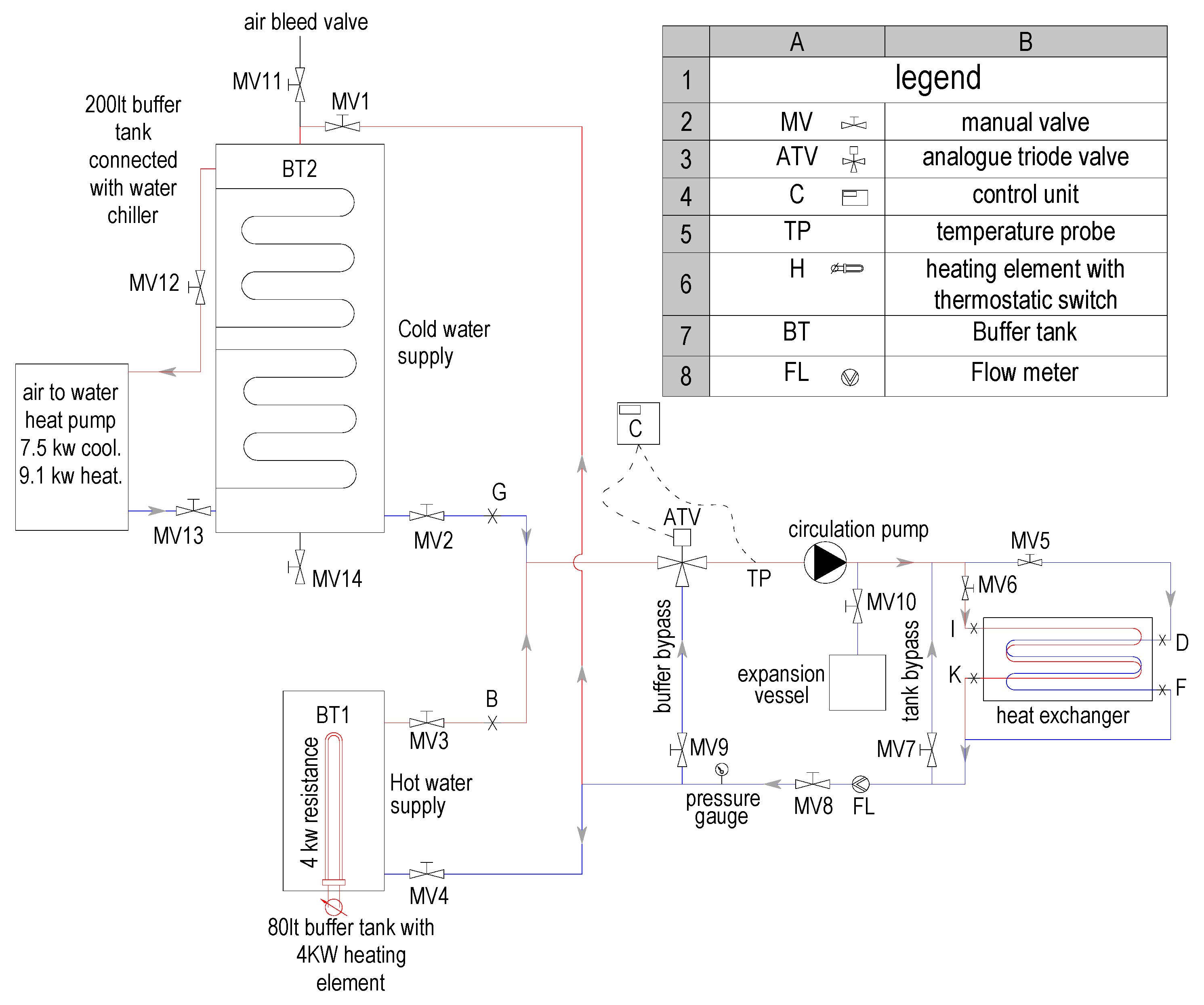
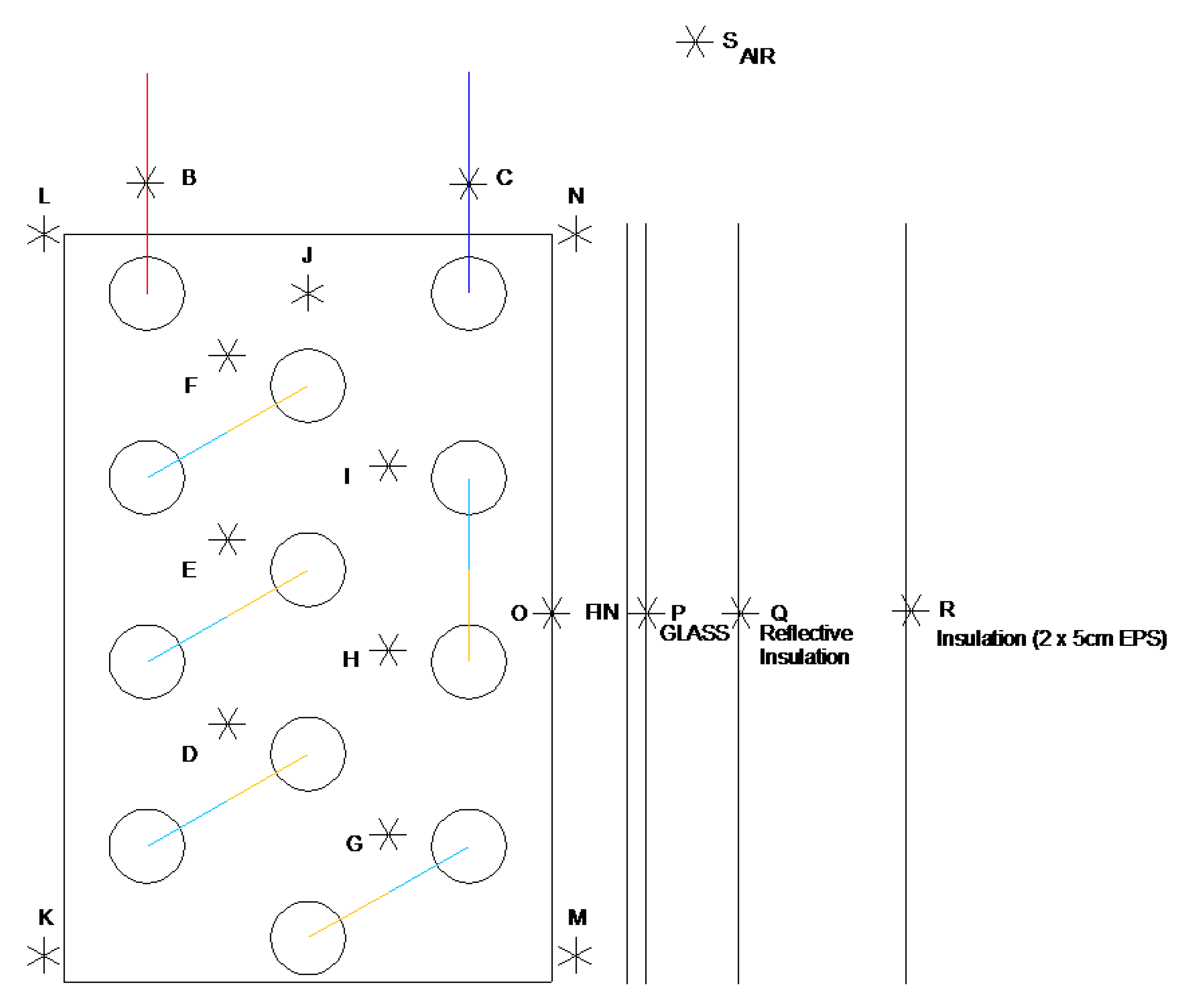
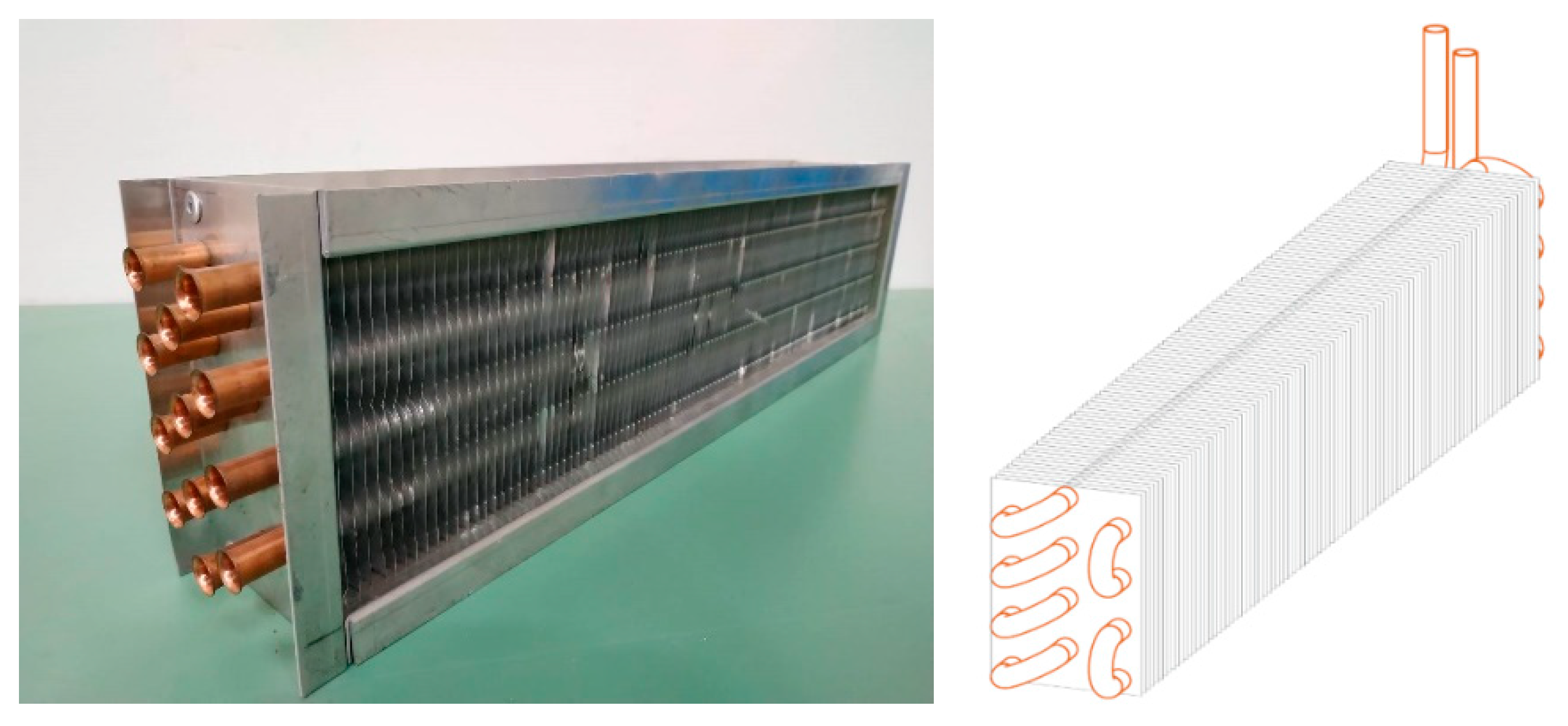
2.1. Description of the LHTES Unit

Figure 1 depicts a hydraulic drawing of the developed test rig in the experiments. It comprises a well-insulated heat storage glass tank, a staggered finned HE, a boiler, a water tank, and other auxiliary equipment. The LHTES glass tank allowed for the visual inspection of the melting and solidification stages [18]. The tank dimensions were 600 mm length, 120 mm width, and 80 mm depth. The tank insulation was composed of two layers. The inner layer was made of an aluminum foil, acting as a reflective insulation against radiation losses. The second layer was composed of two expanded polystyrene blocks with 50 mm thickness each and thermal conductivity equal to 0.034 W/mK. The HE shown in Figure 2 consisted of 12 copper tubes with aluminum fins, having inner and outer diameters of 7.75 mm and 9.525 mm, respectively. The fin thickness and length were 0.3 mm and 68 mm, respectively, while the fin spacing was 5 mm. For the production of hot water, an 80 L boiler with a 4 kW electric heater was used, while for the production of cold water, a 200 L water buffer tank connected to an air-to-water heat pump was used. The PCM volume was 5.7 L (solid) and its mass was 4.73 kg (solid).
The experimental rig also included a circulation pump (Grundfos® ALPHA 2 32–60 180 inverter pump), a three-way temperature control valve (Belimo® LR24A-SR valve and Vector® TCI-W11 controller), a flowmeter (rotameter with a measuring range of 6–60 L/h with ±4% accuracy), thermocouples (T-type, with ±0.5% accuracy), and the necessary piping and valves to regulate water flow. PCM temperatures, HTF inlet/outlet temperatures, and mass flow rate were recorded using a data logger (National Instrument® cDAq—9174 base, 2 × 9213 16 ch cards, LabVIEW® data logger) and a personal computer. The space between the tubes, fins, and the tank was filled with the organic PCM. The experimental process was improved [18] by better stabilizing the inlet water temperature of the HE and therefore producing results that closely match the theoretical calculations. The stabilization was achieved with the use of a triode mixing valve controlled by a digital controller. During the melting (charging) process, hot HTF was supplied from the boiler and its thermal energy was transferred through the HE, thus melting the PCM. HTF inlet temperature was above the melting point of A44. In the solidification (discharging) process, the HTF was supplied by a cold water buffer tank. Cold HTF flowed through the tube solidifying the molten PCM, which released the energy stored during the melting process. Measurements of the water inlet and outlet temperatures and PCM temperatures were obtained. The location of the thermocouples is indicated in Figure 3.

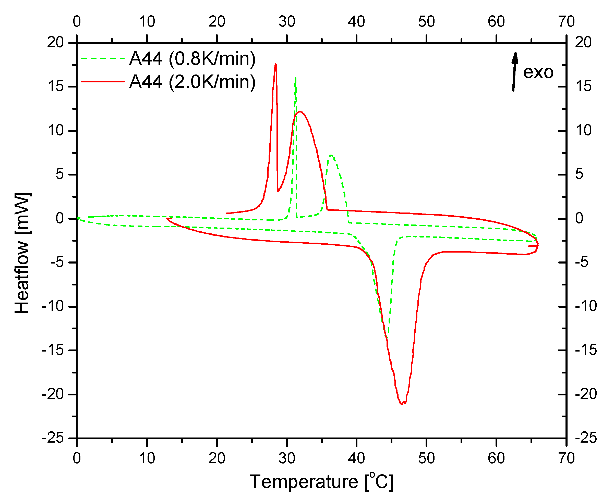
2.2. Organic PCM Properties, Experimental Protocol, and Conditions

The organic PCM used is a commercial product of PCM PRODUCTS® [38] and it was selected considering its low temperature solar thermal energy storage application [6]. Its thermal and physical properties are shown in Table 1. Thermal analysis measurements were conducted by means of DSC tests with a Setaram STA unit under air. DSC results were obtained for heating and cooling in the range 5 to 70 °C with rates of 0.8 °C/min and 2 °C/min. The integration of thermal phenomenon peaks for enthalpy calculation was performed using the CALISTO PROCESSING software [18].
The experimental procedure followed a charging–discharging sequence in a temperature range related to A44 properties. The HTF temperature inlet was controlled by mixing water of the boiler and with the return from the PCM tank using a three-way mixing valve. The charging process was stopped when the temperature difference between the inlet and outlet of the HE inside the PCM tank was less than 1 °C. This ensured that the material had been fully charged. Subsequently, the discharging process was initiated. The inlet temperature was controlled similarly with the charging process by a three-way mixing valve. The discharging process of the experiment ended when the temperature difference between the inlet and outlet was less than 1 °C. The experiments were performed for three HTF flow rates: 30 L/h, 45 L/h and 60 L/h.
In Figure 4, DSC results are shown for heating and cooling cycles up to 70 °C under 0.8 °C/min and 2.0 °C/min. It was found that A44 exhibited a temperature hysteresis upon its solidification, identified as the supercooling effect [18]. This effect was significantly increased at a higher heating or cooling rate i.e., 2.0 °C/min.
Because of this phenomenon, phase-change latent heat release might not be quantitatively captured by the HTF, except if LHTES operation was optimized well within the temperature range of PCM liquid to solid transition. The phase-change region during melting started at 39 °C and the latent heat value had a maximum at 44.4 °C. The latent heat absorption was completed at about 47 °C. In the A44 DSC cooling curve, the two recorded thermal effects showed that latent heat emission occurred in two discrete periods in the range of 35–39 °C (first peak) where latent heat emission began and a second sharp peak at 31 °C was only completed at about 28 °C. Thus, the phase change was completed and the stored energy as latent heat was delivered. Zhang et al. [32,33] prepared a paraffin/expanded graphite (EG) composite phase-change material and differential scanning calorimeter analysis indicated that the melting temperature of the composite PCM was almost similar to that of pure paraffin. XRD (X-ray diffraction) results suggested that the composite PCM was just a combination of paraffin with EG, and no new substance had been produced. Thus, the similarity of the DSC curves was due to the fact that there was no chemical reaction. No significant change in the DSC curves of pure PCM and the enhanced PCM was also observed in this work.

2.3. Repeatability and Error Analysis

All the experiments were performed at least two times in order to assure the consistency of the results. Previous experience with the system and with other storage systems [18] assisted in accomplishing repeatability of the results. Figure 5 depicts an indicative plot of the inlet and outlet water temperatures for the HTF flow rate of 30 L/h. The results for the two typical experiments A and B with the same conditions were similar for the entire charging and discharging procedure.
In Table 2 the accuracy of the temperature and flow rate sensors and A/D converter used in the experiments is shown.
The calculation of uncertainty δ for temperature, T and volumetric HTF flow rate, V: was conducted according to the following equations [39,40]:
δ T = ( 0.15 + 0.002 T ) 2 + ( 0.002 Τ range ) 2 + ( 0.005 T ) 2 3 ,
δ V ˙ = 0.04 V ˙ 3 ,
where Trange, is the temperature range that the thermocouples can measure equal to 110 °C.
The reliability level that was selected was 95% which gave a multiplication factor equal to 2. The relative error is given by:
r e l a t i v e   e r r o r = δ v a l u e 2 v a l u e .
In Table 3, the maximum values of the relative errors for the water temperatures and the relative errors for the volumetric flow rate are listed. The latter were all the same as expected and there was only one value for each flow rate. The thermal power that the water provided (or extracted) to (or from) the system and the environment is given by:
P = m ˙ C p ( T o u t T i n ) .
It was proportional to the difference in the inlet and the outlet temperatures Tin and Tout, respectively, as the flow rate m ˙ and heat capacity Cp of the water were constant. Although the losses were minor due to the sufficient insulation of the system, a small amount of heat that the water provided was lost in the environment.
For the calculation of the thermal power uncertainty, Equation (5) was used, where the heat capacity and the density of water values were considered errorless.
δ P = ( P m ˙ δ m ˙ ) 2 + ( P T o u t δ T o u t ) 2 + ( P T i n δ T i n ) 2 .
Based on the equations of the uncertainty propagation, related errors for the heat power and the accumulated energy were calculated and are summarized in Table 3.

2.4. Nano-Enhancement of Organic Paraffin

Graphite-based nanoplatelets of M15 type were selected for the enhancement of thermal conductivity of the organic PCM with a concentration of 1%. These particles have a very high thermal conductivity, k = 3000 W/m∙K parallel to the surface of the platelets (k = 6 W/m∙K perpendicular to the surface), they can be easily tailored in different dimensions, they have a relatively low cost, and they are simple to produce. It was found that nanoplatelets of expanded graphite mixed in paraffin, increased the thermal conductivity at relative low weight concentrations; 1% and 6% weight fraction of the M15 type, 15 µm diameter, and 6–8 nm thick graphite nanoparticles increased the thermal conductivity by 100% to 250%, respectively. At the same time, the heat of fusion was only slightly reduced from 2 to 10% for the 1% and 6% weight fractions, respectively. Such increases in thermal conductivity might be responsible for the observed change in the shape of the DSC curve for A44 enhanced with nanoparticles (NP) (A44 + NP) (Figure 6).
In Figure 6, DSC results are shown for heating and cooling cycles up to 70 °C under 2.0 °C/min for A44 + NP and without NP. Upon melting, very limited difference was observed among the samples, and the melting peak of A44 + NP now found was slightly sharper. A44 + NP also exhibits supercooling effect [18]. In comparison with the pure A44, the NP-enhanced sample (A44 + NP) showed a slightly modified thermal discharging effect that might be attributed to changes in thermal diffusion due to NP. Although the supercooling effect was initiated in the same temperature as for the pure A44, the second discrete peak was now found with maximum shifted about one degree higher, but with a wider shape. Thus, the solidification thermal effect for A44 + NP was concluded just less of one degree earlier than A44. The latent heat recorded was practically unaffected. These results are in good agreement with previous reports [32,33].
Therefore, still in the case of A44 + NP, phase-change latent heat release might not be quantitatively captured by the HTF as commented previously for the pure A44, except if LHTES operation was optimized within the temperature range of PCM liquid to solid transition.
The experimental set-up used and the procedure followed in the experiments were the same as those in the experiments with the pure PCM. In the following, typical results from the use of HTF flow rate equal to 360 L/h are shown for both pure PCM and enhanced PCM. Special attention was given to manage the problem of sedimentation in PCM nanocomposites, i.e., the nanoparticles were gradually deposited into the bottom of the tank containing the sample (within one to two hours), while usual functionalization of the nanoparticles, e.g., with low density fat acids like oleic acid, prior their mixture with the PCM, or by sonification of the composite, did not seem to induce significant and sustainable improvement. To overcome this issue, ultrasonic agitation was applied. A system composed of two ultrasonic transducers (100 W each) accompanied with a controller was attached on a metallic base (for a better matching of the acoustic impedance) that formed the bottom of the experimental tank filled with the PCM nanocomposite. Also, the thermocouples were replaced by thermistors, as the first were affected by the transducers and the latter did not exhibit any problem in the temperature measurements during the experiments. In Figure 7, the interior of the tank filled with the PCM nanocomposite and the HE during the transducers’ operation is shown. In Figure 6, random bubbles’ upward movement can be identified as captured and the dark regions on the left and right of the tank, where the transducers are located, indicate the initiation of effective agitation.

3. Results and Discussion

In this section, typical results from the experiments carried out to evaluate the LHTES unit performance are presented and discussed. Charging and discharging processes of the material are related to the energy provided (charging) or extracted (discharging) by the HTF [18]. The rate of heat transfer depends on the difference of the HTF inlet and outlet temperatures and specific heat capacity. The effect of the flow rate on the performance of the HE in terms of energy stored is shown. Furthermore, typical results from the testing of the system when using the nanocomposite paraffin are shown.

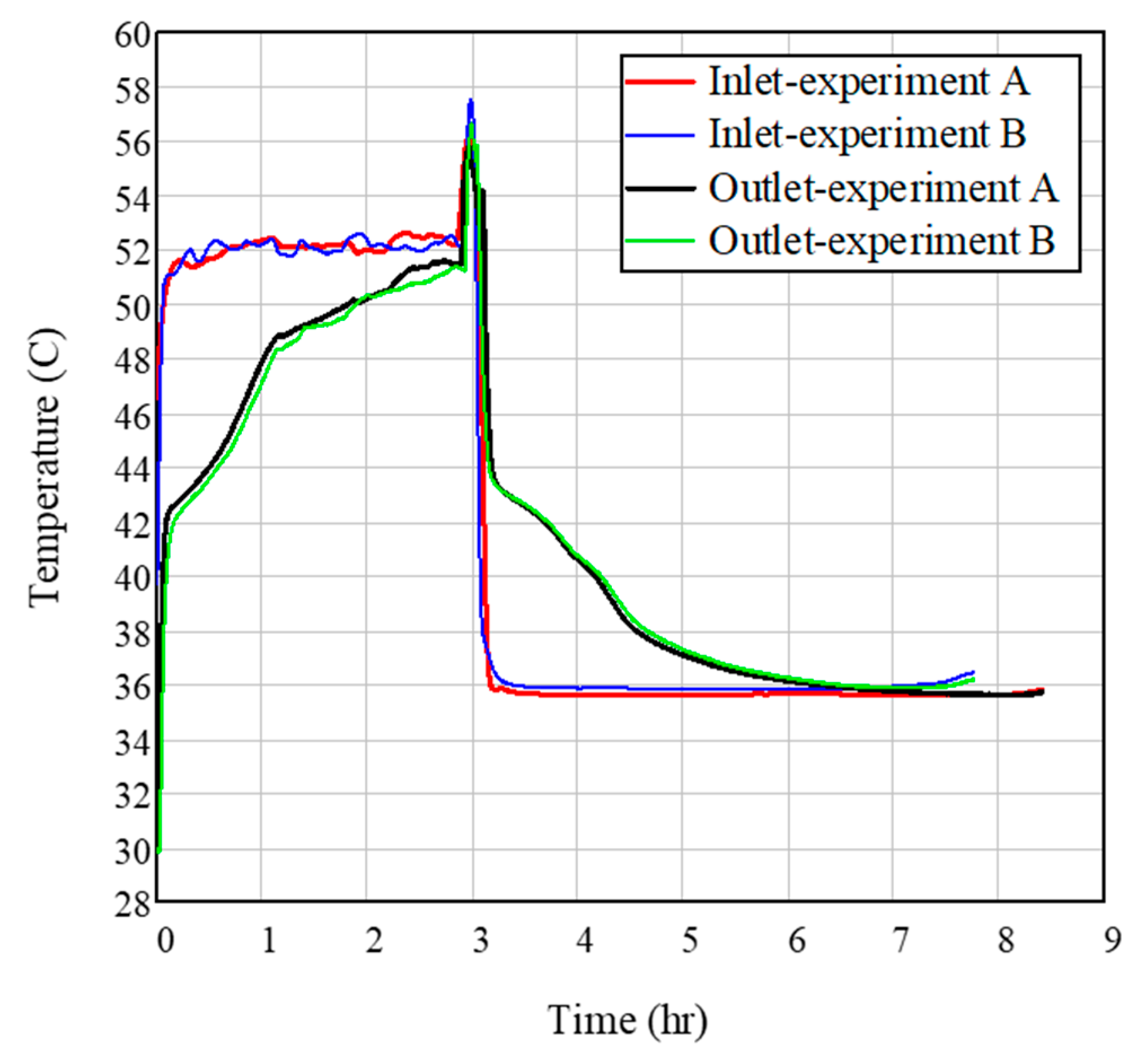
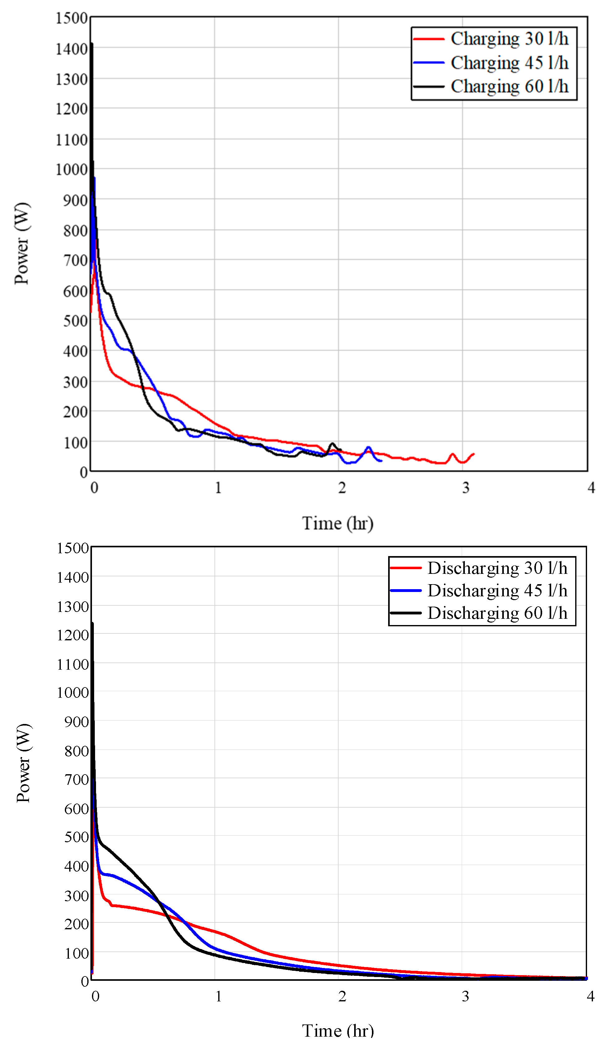
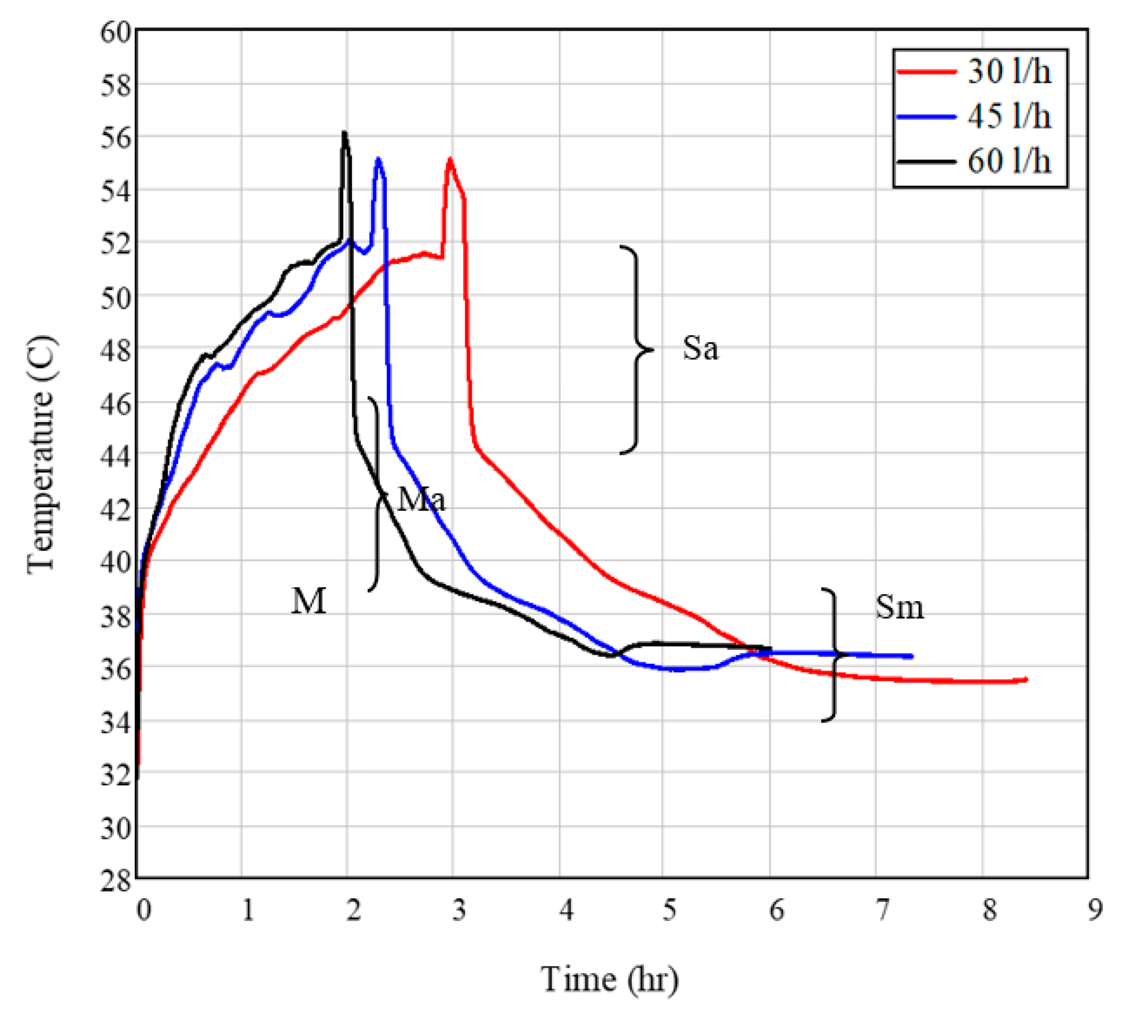
3.1. Effect of Flow Rate on HE Performance

Figure 8 shows mean temperature profiles of A44 for charging and discharging and three HTF flow rates. Τhe mean value has been calculated by the values of the thermocouples placed into the PCM tank (Figure 3). During the charging process, the HTF circulates within the HE pipes transferring its heat to the PCM and the liquid fraction of the latter increases as time progresses. In the beginning of the charging process, the increase in PCM temperature is fast (Regime Ma, Figure 8) until the PCM’s phase transition to liquid starts at 39–40 °C for all flow rates (Point M in Figure 8). This is in agreement with the A44 DSC heating curve (Figure 4) showing that the melting effect begins at 39 °C and the latent heat absorption during melting is completed at about 47 °C for the rate of 0.8 K/min. When the phase change to liquid is completed, the PCM behaves as a usual sensible heat storage medium by storing heat upon increasing its temperature. Then, charging is associated with a steady-state heat transfer rate to the liquid PCM. The procedure is faster for the higher flow rate as expected.
During discharging, a rapid reduction of PCM temperature is observed for all flow rates, where initially sensible heat (Regime Sa) is released and then latent heat when phase change takes place (Regime Sm). The phase transition from liquid to solid is not clear for A44 and this may be due to a possible supercooling phenomenon occurring, despite the narrow temperature range reported by the manufacturer (Table 1). The existence of a supercooling effect is clearly identified by the DSC measurement on the cooling curve. In the A44 DSC cooling curve (Figure 4), the two recorded thermal effects show that latent heat emission occurs in two discrete phenomena in the range of 35–39 °C (first peak) where latent heat emission begins (Regime Sm) and a second sharp peak at 31 °C is only completed at about 28 °C. Thus, the phase change is completed and the stored energy as latent heat may be delivered. In this case, a deviation from product features occurs, which is expected to affect the LHTES operation and efficiency.
In Figure 9, the heat power that is provided to or from the system through the HTF is calculated. In the beginning of the process, high values of the power are shown due to the high temperature difference at the beginning of charging and discharging. However, as the experiment progresses, the heat power decreases as temperatures converge. For higher flow rates, the heat power is higher at the first period of the process. However, it decreases rapidly due to the beforementioned temperature difference decrease. Furthermore, the accumulated energy has been calculated for all flow rates. It is noted that the term “accumulated energy” corresponds to the energy that water delivers/absorbs to/from the system. The term “system” includes the PCM, the copper tubes, the aluminum fins, and the tank. During charging, the energy that water provides, is transferred: (a) as heat tο the tube, the fins, and the glass material, (b) to the PCM as sensible and latent heat and then again as sensible heat, and (c) to the surrounding air as thermal loss. During discharging, the stored energy in the PCM, tubes, fins, and glass material is transferred to the water and to the surrounding air as thermal loss. The accumulated energy for the charging process is calculated to be equal to 0.429 kWh (30 L/h), 0.392 (45 L/h), and 0.391 (60 L/h). For the discharging process, the calculated values are 0.366 (30 L/h), 0.351 (45 L/h), and 0.345 (60 L/h). Due to the insulation of the tank, the thermal losses are small, and the accumulated energy can be utilized as an indicator of the stored energy.

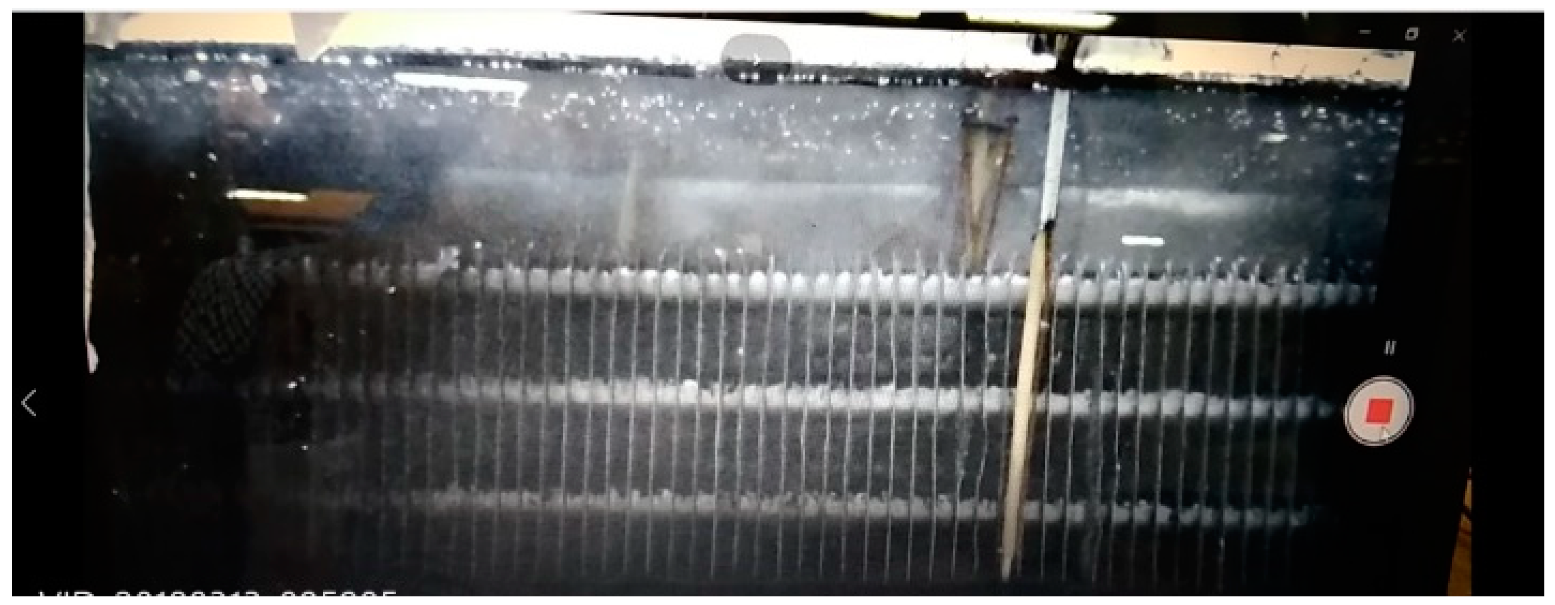
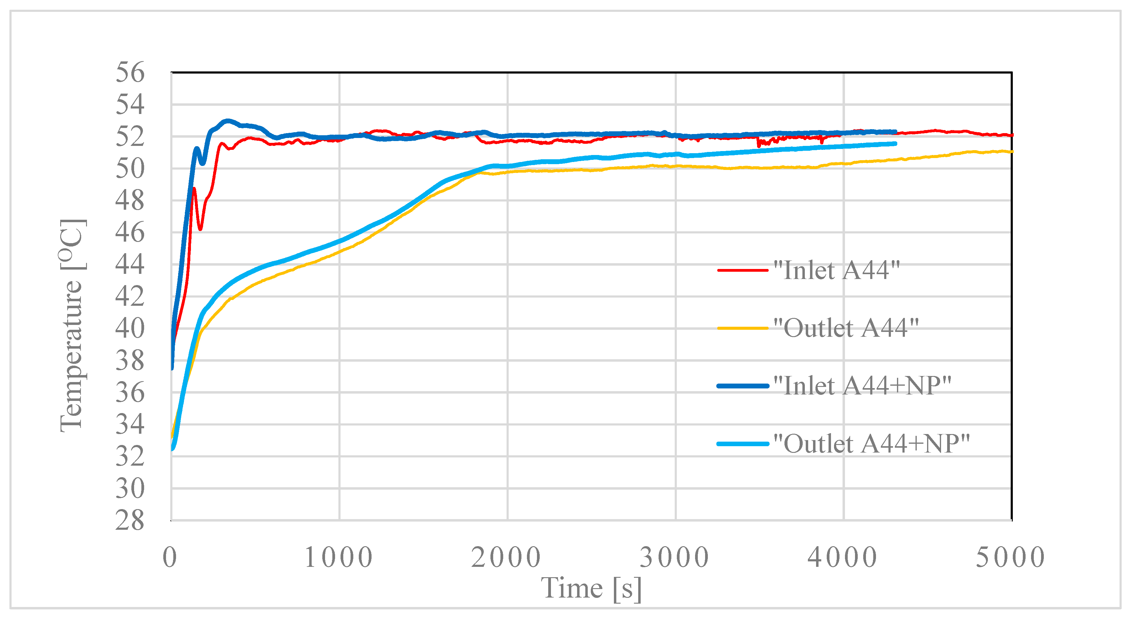
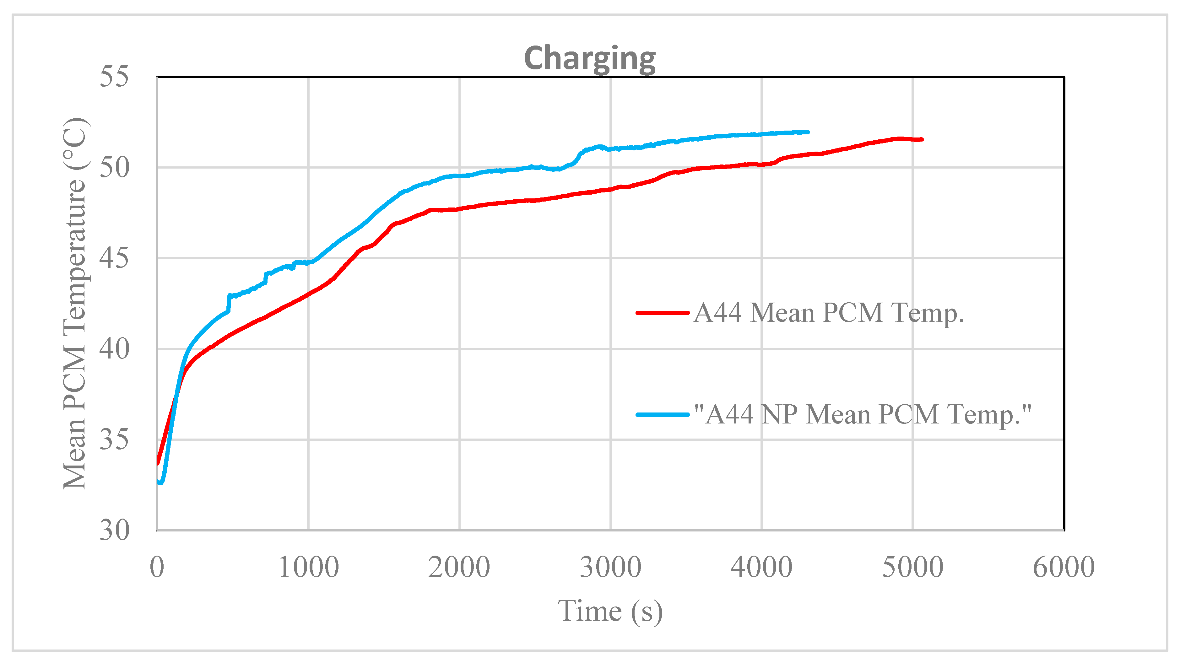
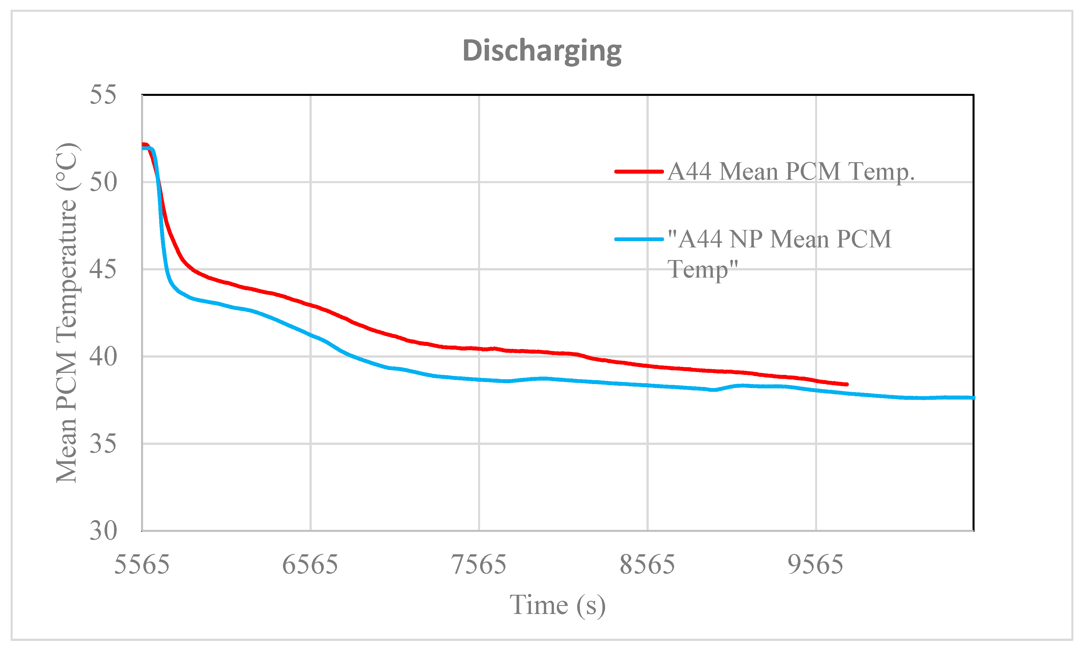
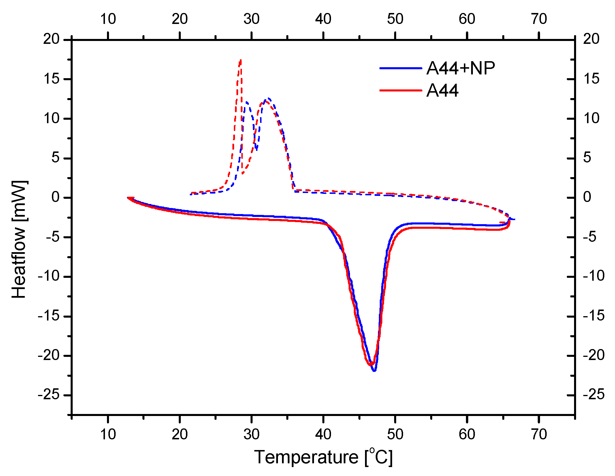
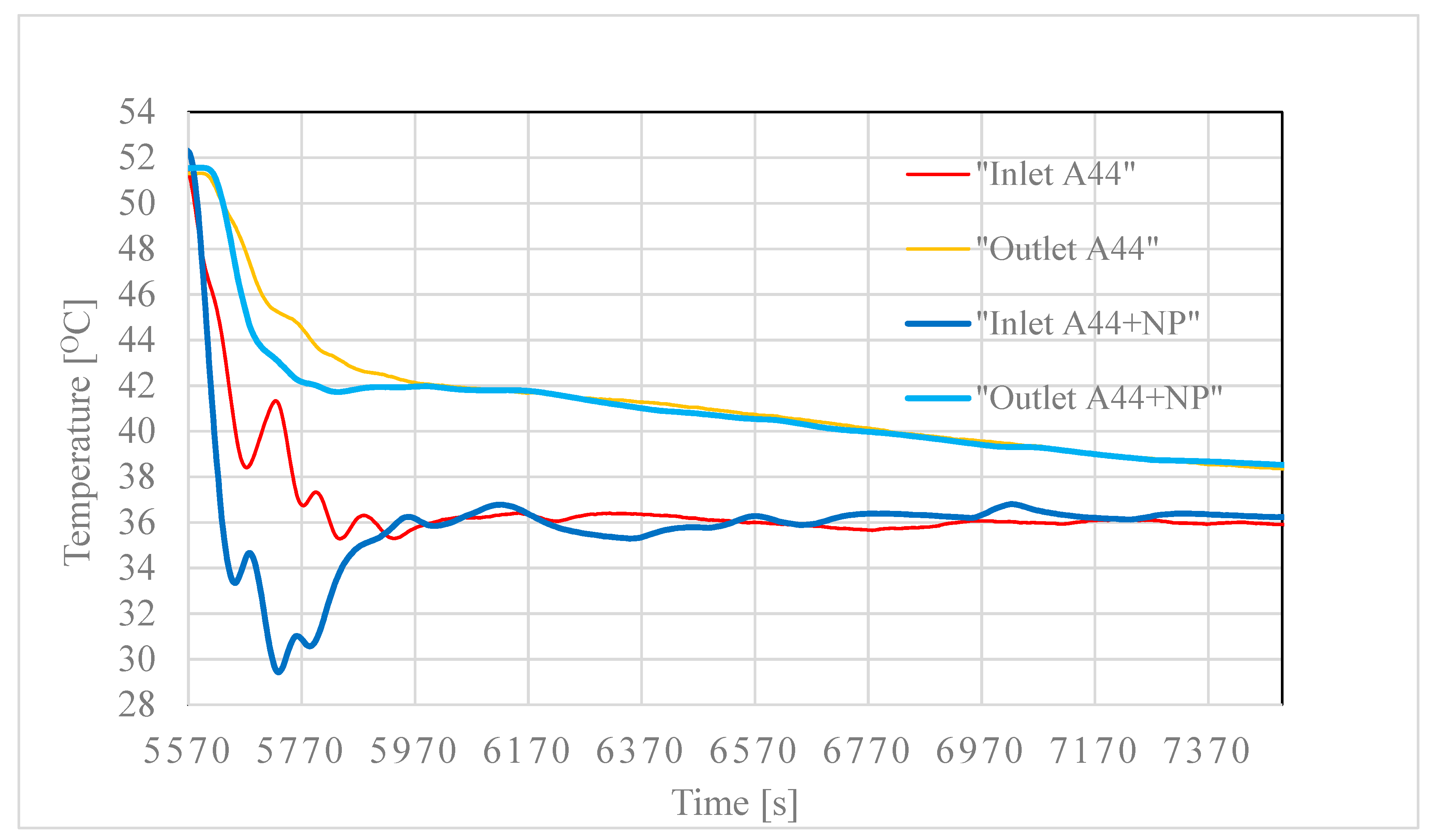
3.2. Testing of the Nancomposite Paraffin Thermal Behavior

From Figure 10, Figure 11, Figure 12 and Figure 13, it is easily seen that charging and discharging of the PCM when it is enhanced with nanoparticles is faster and more efficient, a fact that is due to the higher thermal conductivity of the nanocomposite PCM. The effects are clearer in the mean temperature evolution of the PCM (averaged over three thermistors located at different heights inside the HE) as shown in Figure 12 and Figure 13.
It is obvious from those figures that the nanocomposite A44 reaches faster the target temperature, compared to the pure A44, while some interesting conclusions emerge: (a) charging is clearly faster and quite efficient, in the sense that the provided energy is stored more rapidly and (b) discharging is also faster but the recovered thermal energy is less from what was stored and less compared to the pure A44 case. The explanation for this behavior can arise from the fact that while the more conductive A44 + NP favors a faster heat transfer, which is beneficial in the charging process, in which the PCM is essentially in the liquid or mushy state, upon discharging, the PCM undergoes very quickly the phase transition (exhibiting also some supercooling; see Figure 6) and solidifies in between the fins of the HE, thus impeding the efficient heat transfer between the HE and the PCM, which in fact remains partially at a liquid or gel-like state.
Nevertheless, this otherwise unwanted effect, which occurs at the very beginning of the discharging process (it takes only a few minutes to complete) and is also related with the cooling rate used, is rather easy to overcome by using in the beginning a slower water flow rate at the inlet (down to the melting point ~44 °C) to subsequently increasing it again, thus avoiding the fast freezing of the PCM that is in contact with the fins of the HE. The developed nanocomposite PCM can, therefore, provide a solution for the low thermal conductivity that is a characteristic drawback of these materials for use in thermal storage applications.

4. Conclusions

In this work, the study of an LHTES unit is attempted considering the use of a commercial organic PCM and targeting heating application conditions. The work is a follow up of a previous research [18] where improvements on the unit were applied, while the effect of nano-enhancement of the organic PCM is studied experimentally. The organic PCM used, based on thermal analysis measurements, shows a supercooling effect that influences the performance of the LHTES unit in terms of heat transfer. Based on the research results, it is concluded that the unit with the staggered HE is an effective solution for thermal energy storage; however, careful operation control is needed due to the properties of the thermal storage materials. As phase-change materials exhibit very low thermal conductivity, the thermal transfer mechanisms are crucial to controlling the heat exchange process. From the experimental measurements using graphite-based nanoplatelets to produce the enhanced organic PCM, it is concluded that charging and discharging of the PCM when it is enhanced with nanoparticles are faster and more efficient. Charging is clearly faster and quite efficient as the provided energy is stored more rapidly. Discharging is also faster but the recovered thermal energy is less from what was stored and less compared with the pure A44 case. In the latter case, PCM undergoes phase transition very quickly and solidifies in between the fins of the HE. This drawback, with adequate handling of the water flow rate, can be decreased and the developed nanocomposite PCM can, therefore, provide a solution for the low thermal conductivity for both charging and discharging.

Author Contributions

Conceptualization, M.G.V. and G.E.; methodology, M.G.V., G.E., M.K.K., A.R., and L.C.; formal analysis, G.D., J.K., Christos Pagkalos, M.K.K. and V.S.; experimental measurements, G.E., Costas Prouskas, J.K., V.S. and K.L.; data curation, G.D., J.K., Christos Pagkalos and A.R.; writing—original draft preparation, M.K.K., G.D., V.S., G.E.; writing—review and editing, M.K.K., G.D.; supervision, M.G.V., M.K.K.; funding acquisition, M.G.V., M.K.K. and L.C.

Funding

This research was funded by European Union’s Horizon 2020 research and innovation programme grant No. 680555.

Acknowledgments

This work was financially supported by the TESSe2b project that has received funding from the European Union’s Horizon 2020 research and innovation programme under grant agreement No. 680555. This article reflects only the authors’ view and the European Commission is not responsible for any use that may be made of the information it contains.

Conflicts of Interest

The authors declare no conflicts of interest.

References

  1. Lizana, J.; Chargartegui, R.; Barrios-Padura, A.; Ortiz, C. Advanced low-carbon energy measures based on thermal energy storage in buildings: A review. Renew. Sustain. Energy Rev. 2018, 82, 3705–3749. [Google Scholar] [CrossRef]
  2. Nkwetta, D.N.; Haghighat, F. Thermal energy storage with phase change materials—A state-of-the art review. Sustain. Cities Soc. 2014, 10, 87–100. [Google Scholar] [CrossRef]
  3. Mehling, H.; Cabeza, L. Heat and Cold Storage with PCM—An up to Date Introduction into Basics and Applications; Springer: Berlin/Heidelberg, Germany, 2008. [Google Scholar]
  4. Cunha, J.; Eames, P. Thermal Energy Storage for Low and Medium Temperature Applications Using Phase Change Materials—A Review. Appl. Energy 2016, 177, 227–238. [Google Scholar] [CrossRef]
  5. Palomba, V.; Frazzica, A. Comparative analysis of thermal energy storage technologies through the definition of suitable key performance indicators. Energy Build. 2019, 185, 88–102. [Google Scholar] [CrossRef]
  6. Tesse2b Project Deliverable 8.5: Training Material. Available online: http://www.tesse2b.eu/Content/images/tesse2b/Training_Material.pdf (accessed on 5 September 2019).
  7. Amini, A.; Miller, J.; Jouhara, H. An investigation into the use of the heat pipe technology in thermal energy storage heat exchangers. Energy 2017, 136, 163–172. [Google Scholar] [CrossRef]
  8. Alam, M.; Sanjayan, J.; Zou, P.X.W.; Ramakrishnan, S.; Wilson, J. A Comparative Study on the Effectiveness of Passive and Free Cooling Application Methods of Phase Change Materials for Energy Efficient Retrofitting in Residential Buildings. Procedia Eng. 2017, 180, 993–1002. [Google Scholar] [CrossRef]
  9. Elias, C.; Stathopoulos, V.N. A comprehensive review of recent advances in materials aspects of phase change materials in thermal energy storage. Energy Procedia 2019, 161, 385–394. [Google Scholar] [CrossRef]
  10. Chalkia, V.; Tachos, N.; Pandis, P.K.; Giannakas, A.; Koukou, M.K.; Vrachopoulos, M.Gr.; Coelho, L.; Ladavos, A.; Stathopoulos, V.N. Influence of organic phase change materials on the physical and mechanical properties of HDPE and PP polymer. RSC Adv. 2018, 8, 27438–27447. [Google Scholar] [CrossRef]
  11. Pandis, P.K.; Papaioannou, S.; Koukou, M.K.; Vrachopoulos, M.G.; Stathopoulos, V.N. Differential scanning calorimetry based evaluation of 3D printed PLA for phase change materials encapsulation or as container material of heat storage tanks. Energy Procedia 2019, 161, 429–437. [Google Scholar] [CrossRef]
  12. Languri, E.; Clifford, A.; Alvarado, J. Latent Thermal Energy Storage System Using Phase Change Material in Corrugated Enclosures. Appl. Therm. Eng. 2013, 50, 1008–1014. [Google Scholar] [CrossRef]
  13. Rathod, M.; Banerjee, J. Thermal Performance Enhancement of Shell and Tube Latent Storage Unit Using Longitudinal Fins. Appl. Therm. Eng. 2015, 75, 1084–1092. [Google Scholar] [CrossRef]
  14. Abdulateef, A.M.; Mat, S.; Sopian, K.; Abdulateef, J.; Gitan, A.A. Experimental and Computational Study of Melting Phase-Change Material in a Triplex Tube Heat Exchanger with Longitudinal/Triangular Fins. Sol. Energy 2017, 155, 142–153. [Google Scholar] [CrossRef]
  15. Zhang, Y.; Faghri, A. Heat Transfer Enhancement in Latent Heat Thermal Energy Storage System by Using the Internally Finned Tube. Int. J. Heat Mass Transf. 1996, 39, 3165–3173. [Google Scholar] [CrossRef]
  16. Gasia, J.; Bourke, M.; Van Bael, J.; Cabeza, L. Comparative Study of the Thermal Performance of Four Different Shell-and-Tube Heat Exchangers Used as Latent Heat Thermal Energy Storage Systems. Renew. Energy 2017, 114, 934–944. [Google Scholar] [CrossRef]
  17. Jmal, I.; Baccar, M. Numerical Study of PCM Solidification in a Finned Tube Thermal Storage Including Natural Convection. Appl. Therm. Eng. 2015, 84, 320–330. [Google Scholar] [CrossRef]
  18. Koukou, M.K.; Vrachopoulos, M.G.; Tachos, N.S.; Dogkas, G.; Lymperis, K.; Stathopoulos, V. Experimental and Computational Investigation of a Latent Heat Energy Storage System with a Staggered Heat Exchanger for Various Phase Change Materials. Therm. Sci. Eng. Prog. 2018, 7, 87–98. [Google Scholar] [CrossRef]
  19. Taylor, C. Measurement of Finned-Tube Heat Exchanger Performance. Ph.D. Thesis, Georgia InstituTe of Technology, Atlanta, GA, USA, 2004. [Google Scholar]
  20. Rahimi, M.; Ranjbar, A.; Ganji, D.; Sedighi, K.; Hosseini, M.; Bahrampoury, R. Analysis of Geometrical and Operational Parameters of PCM in a Fin and Tube Heat Exchanger. Int. Commun. Heat Mass Transf. 2014, 53, 109–115. [Google Scholar] [CrossRef]
  21. Paria, S.; Baradaran, S.; Amiri, A.; Sarhan, A.; Kazi, A. Performance Evaluation of Latent Heat Energy Storage in Horizontal Shell-and-Finned Tube for Solar Application. J. Therm. Anal. Calorim. 2016, 123, 1371–1381. [Google Scholar] [CrossRef]
  22. Medrano, M.; Yilmaz, M.; Nogues, M.; Martorell, I.; Roca, J.; Cabeza, L. Experimental Evaluation of Commercial Heat Exchangers for Use as PCM Thermal Storage Systems. Appl. Energy 2009, 86, 2047–2055. [Google Scholar] [CrossRef]
  23. Li, M.; Mu, B. Effect of different dimensional carbon materials on the properties and application of phase change materials: A review. Appl. Energy 2019, 242, 695–715. [Google Scholar] [CrossRef]
  24. Shah, K.W. A review on enhancement of phase change materials—A nanomaterials perspective. Energy Build. 2018, 175, 57–68. [Google Scholar] [CrossRef]
  25. Ramakrishnan, S.; Wang, X.; Sanjayan, J. Thermal enhancement of paraffin/hydrophobic expanded perlite granular phase change composite using graphene nanoplatelets. Energy Build. 2018, 169, 206–215. [Google Scholar] [CrossRef]
  26. Ramakrishnan, S.; Wang, X.; Sanjayan, J. Effects of various carbon additives on the thermal storage performance of form-stable PCM integrated cementitious composites. Appl. Therm. Eng. 2019, 148, 491–501. [Google Scholar] [CrossRef]
  27. Wu, S.; Zhu, D.; Zhang, X.; Huang, J. Preparation and melting/freezing characteristics of Cu/paraffin nanofluid as phase-change material (PCM). Energy Fuels 2010, 24, 1894–1898. [Google Scholar] [CrossRef]
  28. Sharma, G.; Kanwar Singh, M.; Sehgal, S.S.; Sandhu, H. Experimental Study of Thermal Properties of PCM with Addition of Nano Particles. Indian J. Sci. Technol. 2018, 11, 1–5. [Google Scholar]
  29. Shi, J.N.; Ger, M.D.; Liu, Y.M.; Fan, Y.C.; Wen, N.T.; Lin, C.K.; Pu, N.W. Improving the thermal conductivity and shape-stabilization of phase change materials using nanographite additives. Carbon 2013, 51, 365–372. [Google Scholar] [CrossRef]
  30. Yu, Z.T.; Fang, X.; Fan, L.W.; Wang, X.; Xiao, Y.Q.; Zeng, Y.; Xu, X.; Hu, Y.C.; Cen, K.F. Increased thermal conductivity of liquid paraffin-based suspensions in the presence of carbon nanoadditives of various sizes and shapes. Carbon 2013, 53, 277–285. [Google Scholar] [CrossRef]
  31. Khan, Z.; Khan, Z.A. Experimental and numerical investigations of nano-additives enhanced paraffin in a shell-and-tube heat exchanger: A comparative study. Appl. Therm. Eng. 2018, 143, 777–790. [Google Scholar] [CrossRef]
  32. Zhang, Z.; Fang, X. Study on paraffin/expanded graphite composite phase change thermal energy storage material. Energy Convers. Manag. 2013, 47, 303–310. [Google Scholar] [CrossRef]
  33. Zhang, Z.; Zhang, N.; Peng, J.; Fang, X.; Gao, X.; Fang, Y. Preparation and thermal energy storage properties of paraffin/expanded graphite composite phase change material. Applied Energy 2012, 91, 426–431. [Google Scholar] [CrossRef]
  34. Drissi, S.; Ling, T.C.; Hung Mo, K. Thermal efficiency and durability performances of paraffinic phase change materials with enhanced thermal conductivity—A review. Thermochim. Acta 2019, 673, 198–210. [Google Scholar] [CrossRef]
  35. Lin, Y.; Jia, Y.; Alva, G.; Fang, G. Review on thermal conductivity enhancement, thermal properties and applications of phase change materials in thermal energy storage. Renew. Sustain. Energy Rev. 2018, 82, 2730–2742. [Google Scholar] [CrossRef]
  36. Leong, K.Y.; Abdul Rahman, M.R.; Gurunathan, B.A. Nano-composite phase change materials: A review of thermo-physical properties, applications and challenges. J. Energy Storage 2019, 21, 18–31. [Google Scholar] [CrossRef]
  37. Koukou, M.K.; Vrachopoulos, M.Gr.; Konstantaras, J.; Dogkas, G.; Coelho, L.; Rebola, A. Testing the performance of a prototype thermal energy storage tank working with organic phase change material for space heating application conditions. In Proceedings of the International Conference on Advances in Energy Systems and Environmental Engineering (ASEE19), Wroclaw, Poland, 9–12 June 2019. [Google Scholar]
  38. PCM Products. Available online: http://www.pcmproducts.net (accessed on 20 May 2019).
  39. American Association for Laboratory Accreditation. G104—Guide for Estimation of Measurement Uncertainty in Testing; American Association for Laboratory Accreditation: Frederick, MD, USA, 2014. [Google Scholar]
  40. Moffat, R.J. Describing the Uncertainties in Experimental Results. Exp. Therm. Fluid Sci. 1988, 1, 3–17. [Google Scholar] [CrossRef]
Figure 1. Test rig hydraulic drawing.
Chemengineering 03 00088 g001
Figure 2. Heat exchanger photo (left) and drawing (right).
Chemengineering 03 00088 g002
Figure 3. Thermocouples position and tank insulation.
Chemengineering 03 00088 g003
Figure 4. Differential scanning calorimetry (DSC) results of A44 on heating and cooling cycle under 0.8 °C/min and 2.0 °C/min.
Chemengineering 03 00088 g004
Figure 5. Comparison of the inlet and outlet water temperatures of the two same experiments A and B with 30 L/h flow rate.
Chemengineering 03 00088 g005
Figure 6. DSC results of A44 and A44 + NP on heating and cooling cycle under 2.0 °C/min.
Chemengineering 03 00088 g006
Figure 7. The interior of the tank filled with the PCM nanocomposite and the heat exchanger during the transducers’ operation.
Chemengineering 03 00088 g007
Figure 8. Mean temperature profiles of A44 for charging and discharging and three HTF flow rates.
Chemengineering 03 00088 g008
Figure 9. Heat power through HTF temporal evolution for A44 and different flow rates. Top: charging and bottom: discharging.
Chemengineering 03 00088 g009
Figure 10. Comparison of HTF temperature evolution in case of pure A44 and A44 with nano-particles (A44 + NP) upon charging.
Chemengineering 03 00088 g010
Figure 11. Comparison of HTF temperature evolution in case of pure A44 and A44 with nano-particles (A44 + NP) upon discharging.
Chemengineering 03 00088 g011
Figure 12. Mean temperature evolution of pure A44 and A44 + NP upon charging.
Chemengineering 03 00088 g012
Figure 13. Mean temperature evolution of pure A44 and A44 + NP upon discharging.
Chemengineering 03 00088 g013
Table 1. Thermal and physical properties of organic A44 PCM used in the experiments [38].
Freezing Point (°C)45.5
Melting point (°C)44
Latent heat (kJ/kg)268
Density solid (kg/m3)830
Density liquid (kg/m3)775
Thermal conductivity solid (W/m∙K)0.24
Thermal conductivity liquid (W/m∙K)0.24
Specific heat solid (kJ/kg∙K)2.4
Specific heat liquid (kJ/kg∙K)1.8
Table 2. Accuracy of the temperature and flow rate sensors and A/D converter.
AccuracyTemperature, °CVolumetric Flow Rate, Lt/min
Sensor ±(0.005∙Temp)±(0.04∙|Flow|)
Sensor reader±(0.15 + 0.002∙Temp)-
A/D Converter ±(0.002 Temp range)-
Table 3. Maximum relative errors in the water inlet and outlet temperature the flow rate, the power and the accumulated energy.
Flow Rate (L/h)Inlet TemperatureOutlet TemperatureVolumetric Flow RateThermal PowerAccumulated Energy
301.23%1.24%4.62%0.25%5.95%
451.20%1.21%4.62%0.28%6.95%
601.28%1.29%4.62%0.35%7.50%

