Article

Self-Assembled Monolayers of Molybdenum Sulfide Clusters on Au Electrode as Hydrogen Evolution Catalyst for Solar Water Splitting

by
Stephanie Spring
1,†,
Pravin S. Shinde
1,†,
Patricia R. Fontenot
2,
James P. Donahue
2 and
Shanlin Pan
1,*
1
Department of Chemistry and Biochemistry, University of Alabama, Tuscaloosa, AL 35487, USA
2
Department of Chemistry, Tulane University, New Orleans, LA 70118, USA
*
Author to whom correspondence should be addressed.
Authors with equal contribution; Stephanie Spring is The Research Experiences for Undergraduates (REU) student of summer 2018 at The University of Alabama.
Inorganics 2019, 7(6), 79; https://doi.org/10.3390/inorganics7060079
Submission received: 1 May 2019 / Revised: 18 June 2019 / Accepted: 21 June 2019 / Published: 25 June 2019
(This article belongs to the Special Issue Inorganic Materials for Solar Energy Conversion)

Abstract

:
Hydrogen evolution reaction (HER) activities of self-assembled monolayers (SAMs) of [Mo3S7(S2CNMe2)3] and several other MoSx molecular clusters are presented on planer Au electrode. Our study suggests that such Mo-S clusters are unstable under HER reaction conditions of a strongly acidic electrolyte. The [Mo3S7(S2CNEt2)3]I monolayer prepared from DMF showed greater stability among all the studied precursors. The X-ray photoelectron spectroscopy (XPS) analysis on a monolayer of [Mo3S7(S2CNMe2)3]I in THF assembled on Au/ITO suggested sulfur-rich composition with S:Mo ratio of 2.278. The Mo-S monolayer clusters resulting from [Mo3S7(S2CNMe2)3]I in THF showed a Tafel slope of 75.74 mV dec−1 and required a lower overpotential of 410 mV to reach a high HER catalytic current density of 100 mA cm−2 compared to the other studied precursors. Surface coverage of the Mo-S clusters on the Au surface was confirmed by cyclic voltammetry (CV) curves from K3Fe(CN)6 and anodization of Au surface. Further, the rotating ring-disk electrode (RRDE) measurements were performed for the monolayer of [Mo3S7(S2CNMe2)3]I prepared in THF to study its reaction kinetics. The HER catalytic activity of such monolayer Mo-S clusters can further be improved by controlling the sulfur vacancy.

1. Introduction

Due to the adverse environmental effects of fossil fuels and their rapid decrease in availability, there is a growing demand for developing new clean and renewable energy resources. Solar power could be a viable solution to this problem, as it is a readily available and abundant source of renewable energy [1]. One of the popular methods among various emerging power conversion technologies is photoelectrochemical (PEC) water splitting that utilizes solar energy alongside electrochemistry to split water to produce hydrogen-based fuels in solar-to-fuel devices [2]. PEC water splitting involves the following necessary steps: (1) absorption at the photocatalyst such that the photon energy absorbed is more than the band gap energy of the photocatalyst; (2) generation of photo-excited electron–hole pairs; (3) separation of these charges across the surface of the photocatalyst without recombination; and (4) reduction and oxidation of water by the photogenerated electrons and holes to produce H2 and O2 [3]. The first three steps are primarily dependent on the structural and electronic properties of the photocatalyst, whereas the co-catalyst drives the last step. PEC water splitting can be challenging due to the need of thermodynamic potential of −1.23 V vs. RHE at least for the reaction to occur as well as the requirements for an efficient photocatalyst. Some of these requirements include a suitable band gap that lies within 1.6–2.5 eV, band edge position that lies between the redox potentials of H2O, a charge transfer rate fast enough to prevent photocorrosion and shifting of the band edges. The photocatalyst must also be stable, nontoxic, and abundantly available [3]. Most popular and widely employed photocatalysts in solar-to-fuel devices include semiconductors such as TiO2 and ZnO. However, these semiconductors have a higher band gap, which limits the amount of actual sunlight they can utilize and convert to energy. TiO2, for example, has a band gap of 3.0–3.2 eV, which requires UV light to operate. Solar light consists of 5% UV, 43% visible, and 52% infrared light [4]. Therefore, developing a new photocatalyst that exhibits higher activity when exposed to visible light is preferable. However, it is difficult to have such photocatalysts. The semiconductors that are visible-light active are either less catalytic or prone to stability issues. On the other hand, some materials/organic compounds are highly catalytic but do not contribute much under visible-light. Noble metal nanoparticles (NPs) have the potential to address this issue; for instance, Au NPs show high optical absorption in the visible region (500–600 nm) [4,5]. The approach is to synergistically improve the water splitting performance by combining the visible-light-absorbing and highly catalytic materials. Platinum is the best-known electrocatalyst for the hydrogen evolution reaction (HER). However, its scarcity and enormous cost make it a poor choice for use in solar-to-hydrogen devices. Therefore, developing low-cost and Earth-abundant catalysts with a performance comparable to that of Pt-group metals is crucial [6]. Some examples of Earth-abundant HER electrocatalyst include transition metal-based sulfides (e.g., MoS2 [7], CoS2 [8], and WS2 [9]), selenides (e.g., MoSe2 [10], NiSe2 [11], and CoSe2 [12]), phosphides (e.g., Ni2P [13] and FeP [14]), carbides (e.g., Ni/C [15] and MoC [16]), and molecular organic catalysts (e.g., cobalt and nickel diimine-dioxime complexes [17] and ligand-centered homogeneous electrocatalysts [18]). Recently, monolayers of metal chalcogenide-based molecular catalysts are gaining interest due to their structural tunability and low-cost production [19,20].
Molybdenum sulfide (MoS2) is one such promising candidate, which has the potential to replace precious metal catalysts for sustainable development towards hydrogen generation. MoS2 is a renowned HER catalyst, known for its excellent ability to absorb hydrogen and activate it for the reduction of organo-sulfur and organo-nitrogen molecules in the hydrotreating of crude petroleum. Several forms of molybdenum sulfide such as amorphous MoSx [21,22], crystalline MoS2 [23,24], sulfur-rich [25,26] or sulfur-deficient [27,28] MoS2, and metal-promoted MoS2 [29] have been synthesized on conducting substrates via simple solution-based chemical techniques that includes drop-casting, dip-coating, hydrothermal, and electrodeposition. Such HER electrocatalysts achieved a Tafel slope in the range of 39–95 mV dec−1 and overpotential in the range of 150–300 mV at 10 mA cm−2 [30].
Various speculations about the origin of the catalytic ability of MoS2 have been reported in the literature ranging from edge site configuration to sulfur vacancy, to the assembled structure of MoS2 [4,31,32]. Regarding sulfur vacancy, it was observed that a vacancy density of 7–10% could drastically shift the onset potential to more positive potentials [32]. A variety of studies have been conducted in trying to maximize the catalytic ability of MoS2 by changing the concentration, the method of MoS2 deposition, the number of layers deposited, and the semiconductor material [4,24]. A few of these studies have chosen to study as-grown MoS2, which requires several days to synthesize the as-grown MoS2 [31,33]. Our team recently demonstrated a simple method of coating catalytic MoS2 layer onto Cu2O photocathode to enhance its stability and hydrogen evolution reaction under sunlight illumination [24]. MoS2 coating on top of Cu2O has been achieved by spin coating appropriate amount of [Mo3S7(S2CNEt2)3]I precursor solution combined with a thermal annealing process to obtain the optimal stoichiometry. MoS2 thin films synthesized using this method exhibited good prospects as both a protective layer and an electrocatalyst for hydrogen evolution reactions (HER) due to excellent stability and high electrocatalytic activity, as shown in Figure 1. Through this work, we demonstrated a sustained proton reduction performance from Cu2O photocathode using ~40 nm thick coating of MoS2, which was prepared by spin-coating three layers of 2.5 mM MoS2 precursor solution on the Cu2O surface. Although the enhanced catalytic performance for HER from two-dimensional (2D) MoS2 has been widely reported in the literature, the role of monolayer MoS2 is still not well understood. Few reports on monolayer MoS2 have been concentrated on investigating their electrochemical and kinetic properties using CV, XPS, and RRDE techniques, and Tafel slope measurements to understand the HER mechanisms.
Here, we propose using Au instead of Cu2O due to the Au–S bond being relatively strong and easy to assemble the MoSx. Assembling MoSx monolayers on Au should increase the rate of interfacial charge transfer because the increased number of terminal S-atoms on MoSx precursor derivatives act as active sites for proton reduction [34,35]. Here, we self-assembled the monolayers of MoSx on to Au from different MoSx precursor derivatives using immersion, spin-coating, drop-casting and air-drying techniques in an attempt to explore the role of monolayer MoSx through CV and RRDE measurements and Tafel slope calculations.

2. Results and Discussion
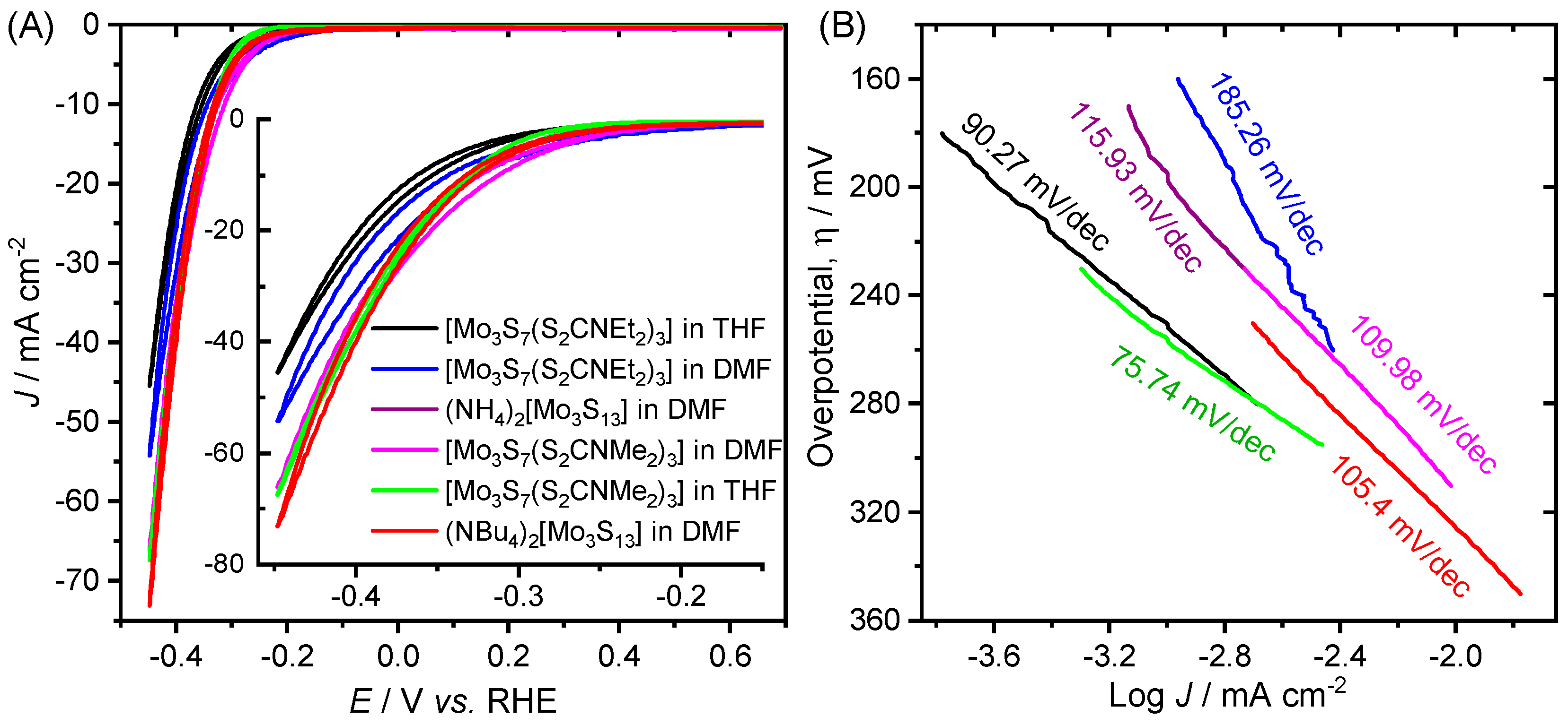
Prior to studying their monolayer performances for proton reduction reaction, we previously demonstrated the proton reduction characteristics of thin films resulting from [Mo3S7(S2CNMe2)3]I precursor and a few other precursor derivatives such as Mo3S7(S2CNEt2)3I, Mo3S4(S2CNEt2)4, (NH4)2[Mo3S13], and (NBu4)2[Mo3S13]. These precursors were spin-coated onto the conducting FTO glass substrates using organic solvents such as THF, DMF, or CH2Cl2 to obtain catalytic films on FTO. Owing to their limited adherence and stability on FTO, the spin-coated films were annealed at 450 °C for 1 h in a N2 environment to obtain crystalline MoS2. The proton reduction HER curves for all the derivatives are shown in Figure 2.
The MoS2 film obtained from [Mo3S7(S2CNMe2)3]I in THF exhibited the most promising HER activity. All other films obtained by the post-annealing treatment showed more or less enhanced HER activities than the bare FTO substrate. The major issues with this thin film study are that intrinsic molecular catalytic activities are missing. Therefore, there is a need to prepare self-assembled monolayers (Figure 3) of these molecular precursors on a conductive surface such as gold to learn their proton reduction kinetics.
The benefits of using a monolayer configuration instead of thin films of the Mo-S molecular clusters include: (1) short charge transfer distance for catalyzing proton reduction; (2) intrinsic catalytic characteristics are more likely to be retained than the results shown in Figure 2; and (3) there is no mass transfer effect of molecular catalysts for proton reduction reaction in such heterogeneous system in comparison to that of a homogenous molecular catalysis system for proton reduction.
An XPS study was performed on the 1 × 1 cm2 ITO coated with Au and the most stable MoSx precursor, [Mo3S7(S2CNEt2)3]I in DMF, to determine the chemical composition of the Mo-S layer. Figure 4A shows the survey spectrum of [Mo3S7(S2CNEt2)3]I precursor assembled on Au-coated ITO surface. The quantitative analysis of the survey spectrum (inset of Figure 4A) revealed the presence of Mo at 30.51% and sulfur at 69.49%. The actual sulfur-to-molybdenum ratio (S:Mo) obtained from XPS study is ca. 2.278 (69.49:30.51), indicating the formation of sulfur-rich MoSx monolayer complex on the Au surface. Figure 4A also indicates the presence of nitrogen, carbon, and iodine, all of which are present in the precursor derivative. Figure 4B depicts the deconvoluted high-resolution XPS spectra of Mo 3d, S 2p, and C 1s lines. The two peaks at 229.5 eV and 232.7 eV can be attributed to the doublet Mo 3d5/2 and Mo 3d3/2, respectively, while the broad peak at 226.9 eV can be identified as S 2p [31]. The peaks located at 163.7 and 162.5 eV can be ascribed to the S 2p1/2 and S 2p3/2 peaks, respectively. These results are consistent with other reported results for non-stoichiometric MoS2, indicating that the other elements present are impurities rather than the precursor staying intact and being entirely deposited onto the Au surface [36]. For XPS measurement, the substrate was annealed with nitrogen in an attempt to determine whether the entire precursor remained intact and was deposited onto the Au surface or if the nitrogen and iodine are impurities. The source of the Ag impurity is unknown but suspected to arise from an impurity in the potassium aurocyanide used to deposit the thin film of Au on to ITO.
To examine the surface coverage of MoSx from [Mo3S7(S2CNMe2)3]I in THF, the precursor was deposited onto the Au-disc electrode and run in a solution of 0.1 mM K3Fe(CN)6 in 1 M KNO3 at different scan rates. Figure 5 shows the CVs at different scan rates revealing the reduction of electroactive species (ferricyanide to ferrocyanide) in the K3Fe(CN)6 electrolyte and subsequent oxidation at the surface of Au-disc electrode, before and after modification with the Mo-S clusters, where the current density increases as the scan rate increases.
For 100% surface coverage, it is expected that the oxidation and reduction peaks would disappear, assuming that K3Fe(CN)6 does not reduce or oxidize at the surface of the MoSx monolayer. Thus, since the “before” and “after” CV profiles look relatively similar, inadequate surface coverage is expected.
To determine the electrochemically active surface area before and after the coating of MoSx, the anodic (or cathodic) peak currents in Figure 5A,B are plotted against the square root of scan rate (ν) in Figure 6A,B. The linear dependence of Ipa against ν−1/2 plot means that the electrode reaction is diffusion-controlled. This type of plot is derived from the Randles–Sevcik equation,
Ip = 2.69 × 10⁵ × AESCA × n3/2D1/21/2
where, Ip is the peak current (anodic or cathodic), AESCA is the electrochemically active surface area, D1/2 is the diffusion constant for the electrolyte (D = 6.20 × 10⁻⁶ cm2 s−1 for K3Fe(CN)6), n is the number of electrons transferred (n = 1 for [Fe(CN)6]3−/4−), ν is the scan rate, and C is the concentration of the electrolyte [37]. Using the slope in Figure 6, the Randles–Sevcik equation can be rewritten as follows:
A E S C A = S l o p e   ( I p   v s .   v 1 / 2 ) 2.69   ×   10 5   ×   n 3 / 2   ×   D 1 / 2   ×   C
The change in the electrochemically active surface area (ΔAESCA) was calculated to be 3.4 × 10⁻⁵ cm2. The percentage of MoSx coverage can also be calculated from the electrochemically active surface area using the area calculated using both the anodic and cathodic peak currents before and after Mo-S cluster modification, with the percent coverage of ca. 4.7%. This calculation may not be completely accurate, as it assumes that the K3Fe(CN)6 cannot be reduced or oxidized at the surface of the MoSx monolayer. However, this is not the case when sufficient overpotential is supplied to overcome the potential barrier of the Mo-S molecular clusters self-assembled onto the Au surface.
Then, the polarization curves of a bare Au/ITO electrode and the MoSx/Au/ITO electrodes prepared by dip-coating (overnight immersion) and spin-coating methods were recorded and analyzed. Figure 7 shows the CV curves of bare Au/ITO and MoSx-coated Au/ITO electrodes recorded at the scan rate of 50 mV s−1 from 0.5 M H2SO4. All the Au/ITO electrodes underwent oxidation except the one that was immersed overnight in the Mo-S precursor solution. There seems to be little change in the current density for the electrodes. This could be because the electrode is rich in sulfur, as indicated by the XPS quantitative data. Because sulfur vacancy has been reported to influence the catalytic activity, it is fair to conclude that sulfur-rich MoSx on Au/ITO electrode could be hindering its catalytic ability to be an efficient HER catalyst.
The surface coverage of the MoSx monolayer was calculated for the immersed substrate for comparison to the data calculated from scan-rate dependent CV studies using potassium ferricyanide. The immersed MoSx/Au/ITO electrode was used as it is not prone to Au oxidation, indicating that it may have adequate surface coverage. To calculate the surface coverage of MoSx, the oxidation peaks for bare Au/ITO and the one dipped overnight were integrated, yielding a surface coverage of 64.4%.
To gain insight as to which MoSx precursor derivative would produce the best HER electrocatalytic activity, CVs were recorded on each of the Au disc electrodes immersed overnight in different MoSx precursor solutions. Figure 8A indicates that (NBu4)2[Mo3S13] in DMF has the highest current density and the [Mo3S7(S2CNEt2)3]I in DMF has the lowest onset potential, which is the minimum potential required for initiation of the catalytic reaction. Repeated CV scans were recorded for each precursor derivative. It is observed that the current density decreased with each scan for each precursor derivative, except for [Mo3S7(S2CNEt2)3]I in DMF. This observation indicates that most of the MoSx derivatives were unstable under these conditions.
To better understand the HER kinetics of the MoS2-modified Au disc electrode, the polarization curves in Figure 8A are plotted in Figure 8B as overpotential (η) versus the logarithm of current density (J). This type of plot is known as a Tafel plot. The linear portion near the onset of current is fit to the Tafel equation η = b logJ/J0, where J is the current density, J0 is the exchange current density, and b is the Tafel slope. The Tafel slope is regarded as a measure of catalytic ability. A lower Tafel slope is optimal for Pt-group electrode, which is the best HER catalyst having a Tafel slope of 30 mV dec−1. The MoSx precursor that was the most stable Au, i.e., [Mo3S7(S2CNEt2)3]I in DMF, has the highest Tafel slope of 185.26 mV dec−1, indicating that it is not a suitable HER catalyst.
The HER activity of a catalyst in acidic electrolyte generally follows one of two reactions pathways—the Volmer–Tafel or the Volmer–Heyrovsky mechanism—to reduce the protons (H+) to hydrogen (H2). These mechanisms proceed through three reaction steps decided by the Tafel slopes. The rate-limiting steps can be [24]:
(i)
Electrochemical hydrogen adsorption, H3O+ + e → Hads + H2O (Tafel slope: 120 mV dec−1)
(ii)
Electrochemical desorption, Hads + H3O+ + e → H2 + H2O (Tafel slope: 40–120 mV dec−1)
(iii)
Chemical desorption, Hads + Hads → H2 (Tafel slope: 30–40 mV dec−1)
The precursor [Mo3S7(S2CNMe2)3]I in THF is thus far the best candidate for HER among all the studied precursors because of its optimal properties in terms of Tafel slope and overpotential. MoSx resulting from this precursor exhibits a low Tafel slope of 75.74 mV dec−1 and requires the low overpotentials of 331 mV and 410 mV to fetch the HER current densities of 10 and 100 mA cm−2, respectively. From the Tafel slope, we can infer that the MoSx monolayer formed using [Mo3S7(S2CNMe2)3]I in THF follows the Volmer–Tafel mechanism. All these Mo-S clusters are interesting HER catalysts in homogenous solution because of the facile loss of sulfur from the bridging disulfide (S22−) ligands and favorable interaction with protons to facilitate proton reduction upon charge interaction. For example, our study with [Mo3S7(S2CNiBu2)3]I suggested superior high turnover frequency of several hundred in several hours during homogeneous photolysis experiments because of its good solubility and favorable HER activities. The difference in the HER activities of these self-assembled derivatives might be associated with the surface coverage and bonding orientation on the Au electrode surface.
To further study the kinetics of this particular precursor, a RRDE study was conducted using glassy carbon (GC) disc electrode. Figure 9 shows the current density responses obtained from MoSx coated-GC electrode. Protons are reduced on the GC electrode (with or without Au and MoSx coating) resulting in H2 molecules. The disc current density was higher, and the onset potential was lower for the MoSx-coated GC and Au/GC electrodes suggesting that [Mo3S7(S2CNMe2)3]I self-assembled onto the Au surface is a promising HER catalyst. More work is needed to further understand the stability of such MoSx monolayers and the structural defects through spectroscopy and high-resolution transmission electron microscopy techniques.

3. Materials and Methods

3.1. Materials

Potassium ferricyanide (K3Fe(CN)6, 99%, Fisher Scientific, San Jose, CA, USA), potassium aurocyanide (KAu(CN)2, Orotemp 24, Technic, Cranston, RI, USA), acetone, ethanol, tetrahydrofuran (THF), hydrosulfuric acid (H2SO4, 18.4 M), nitric acid (KNO3, 15.6 M) and dimethylformamide (DMF) were used as-received without further purification. Commercially available transparent and conducting indium-doped tin oxide (ITO 15–20 Ω cm−2)-coated glass substrates were used for thin film deposition of Mo-S precursors. The syntheses of (NBu4)2[Mo3S13], [Mo3S7(S2CNMe2)3]I, (NH4)2[Mo3S13], [Mo3S7(S2CNEt2)3]I, [Mo3S7(S2CNiBu2)3]I, and [Mo3S7(S2CNiBu2)3]PF6 were detailed in our previous published work [24].

3.2. Preparation and Assembling of Monolayer on Au-Disc Electrode

The Au-disc electrode (area = 0.0314 cm2) was polished using 0.3 μm Al2O3, then 50 nm Al2O3, and finally 0.3 μm Al2O3 polish for 5 min each, moving the electrode in a figure eight motion. The electrode was sonicated in deionized (DI) water for 1 min and then dried under nitrogen steam between each polish and at the end before immersing the electrode in the solution. The MoSx precursor solutions were all 0.1 mM in 10 mL of their respective solvents, which were prepared by dilution from a freshly prepared 1 mM stock solution. All solutions were sonicated for 10 min to ensure the precursor was completely dissolved. The Au-disc electrode was immersed such that it remained suspended in the Mo-S precursor solution overnight.

3.3. Preparation and Assembling of Monolayer on Au/ITO Electrode

ITO strips were cut into 1 × 2 cm2 (or 1.5 × 2.5 cm2 for spin coating) strips and then subsequently cleaned using detergent, DI water, acetone, and ethyl alcohol and DI water, each for 10 min in an ultrasonic bath, and finally dried under a nitrogen stream. A thin film of Au was deposited onto the surface of ITO using CV technique in a three-electrode configuration using ITO as the working electrode, graphite as the counter electrode, and silver/silver chloride (Ag/AgCl sat. KCl) as the reference electrode from KAu(CN)2 electrolyte. The CV was scanned from 0 to −1.5 for 1 cycle at the scan rate of 50 mV s−1. The Au-coated ITO electrodes were immediately washed in DI water and dried with air. Two Au/ITO substrates (size 1 × 2 cm) were immersed overnight in a 0.1 mM solution of [Mo3S7(S2CNEt2)3]I in DMF. One substrate was cut down to 1 × 1 cm2 for X-ray photoelectron spectroscopy (XPS). The Au/ITO substrate (size 1.5 × 2.5 cm2) was immersed overnight in a 0.1 mM solution of [Mo3S7(S2CNMe2)3]I in THF. Two Au/ITO substrate (size 1.5 × 2.5 cm2) were cut down to 1.5 × 1.5 cm2 for spin coating. An 80 μL drop of 0.1 mM solution of [Mo3S7(S2CNMe2)3]I in THF was dropped onto the Au/ITO substrate. One was prepared at 2000 rpm, and the other was prepared at 3000 rpm.

3.4. RRDE Study

The RRDE voltammograms were recorded on an RRDE with GC-Pt configuration (ALS Co., Ltd., Tokyo, Japan) having two working electrodes such as glassy carbon (GC) disc (area = 0.5 cm2) and Pt ring electrode (area = 0.75 cm2). The RRDE was sonicated for 1 min in ethanol followed by sonication in DI water for 1 min and dried under a nitrogen stream. All measurements were performed in 0.5 M H2SO4 electrolyte at room temperature at the scan rate of 50 mV s−1 using a three-electrode system consisting of the RRDE as the working electrode, silver/silver chloride (Ag/AgCl with sat. KCl) as the reference electrode and a platinum coil as the counter electrode. The rotational speed was varied from 0 to 6400 rpm by squares, and any bubbles on the surface of the working electrode were removed between each measurement. A layer of Au was deposited onto the surface of GC using the same method as depositing Au onto ITO. A layer of MoSx was deposited onto the surface of GC (or Au/GC) by drop-casting and air drying a 5 µL drop of 0.1 mM [Mo3S7(S2CNMe2)3]I in THF.

3.5. Proton Reduction Measurement

All polarization curves were performed using the following instruments unless otherwise indicated: an electrochemical workstation (CHI 760c, CH Instruments, Austin, TX, USA) and a three-electrode system with graphite or platinum coil as the counter electrode, silver/silver chloride (Ag/AgCl sat. KCl) as the reference electrode, and Au-disc electrode as the working electrode. The graphite was washed with DI water and dried with air, and the Ag/AgCl electrode was washed with DI water before recording the CV. The electrolyte used for the proton reduction measurements was 0.5 M H2SO4. The CV curves were scanned from open circuit potential (OCP) to −0.7 V vs. Ag/AgCl for 1 cycle at the scan rate of 100 mV s−1. The MoSx/Au/ITO electrodes prepared by overnight immersion and spin-coating methods using [Mo3S7(S2CNMe2)3]I in THF were assembled in a three-arm electrochemical reactor with an electrolyte exposure area of 0.1807 cm2. All the potential measurements were taken against the Ag/AgCl reference electrode and are reported versus the reversible hydrogen electrode (RHE) using the Nernst Equation below:
ERHE = EReference + 0.059 × pH + E°Reference
where ERHE is the converted potential versus RHE, EReference is the potential measured versus the reference electrode (Ag/AgCl sat. KCl), and E°Reference is the standard potential of the reference electrode (0.1916 V for Ag/AgCl at 25 °C). The CVs of the Au-disc electrodes, both bare and coated with [Mo3S7(S2CNMe2)3]I in THF through immersion for surface coverage calculations were recorded in 1 mM K3Fe(CN)6 in 0.1 M KNO3 at different scan rates such as 0.025, 0.05, 0.1, 0.25, and 0.5 V s−1.

4. Conclusions

We successfully assembled the monolayer of MoSx precursor clusters such as (NBu4)2[Mo3S13], [Mo3S7(S2CNMe2)3]I, (NH4)2[Mo3S13], [Mo3S7(S2CNEt2)3]I, [Mo3S7(S2CNiBu2)3]I, and [Mo3S7(S2CNiBu2)3]PF6. XPS study of MoSx monolayer assembled on Au using [Mo3S7(S2CNMe2)3]I in THF showed sulfur-rich Mo-S clusters with Mo at 30.51% and sulfur at 69.49%. The catalytic activity of MoSx monolayer is hindered by sulfur-rich clusters, which could be improved by the creation of sulfur vacancies. By comparing various MoSx precursors, we were able to identify the most catalytically active precursor to be [Mo3S7(S2CNMe2)3]I in THF, as it has the optimal properties of having a relatively low Tafel slope of 75.74 mV dec−1 and requiring a lower overpotential of 410 mV to reach a high current density of 100 mA cm−2 compared to the other studied precursors. The electrochemically active surface area of MoSx monomer obtained using this particular precursor was calculated using two different ways with drastically different results, those being 4.7% from the ferricyanide study and 64.4% from the spin coating study. The reason for these different results could be due to assuming that ferricyanide does do not reduce at the surface of MoSx monolayer, which may have been inaccurate. Thus, it is assumed that 64.4% of surface coverage is a more probable result, as is evident by higher catalytic current density.

Author Contributions

J.P.D. and S.P. conceived and supervised the experiments; P.S.S. and S.S. conducted the electrochemistry and material characterization for proton reduction reaction and XPS characterization; P.R.F. synthesized the Mo-S molecular clusters; and P.S.S. and S.S. analyzed the results and wrote the manuscript. P.S.S. and S.S. hold an equal contribution.

Funding

This research was funded by the National Science Foundation (NSF), grant numbers OIA-1539035, and CHE-1508192.

Acknowledgments

We acknowledge the support of National Science Foundation (NSF) under award number OIA-1539035 and CHE-1508192. We also thank Central Analytical Facility of the University of Alabama for the major characterization facility and Tulane University for providing the precursors used in this study. We also thank Michael Buettner, the research facilities manager of the MINT center, for his assistance with all the XPS measurements.

Conflicts of Interest

The authors declare no conflict of interest.

References

  1. Blankenship, R.E.; Tiede, D.M.; Barber, J.; Brudvig, G.W.; Fleming, G.; Ghirardi, M.; Gunner, M.R.; Junge, W.; Kramer, D.M.; Melis, A.; et al. Comparing Photosynthetic and Photovoltaic Efficiencies and Recognizing the Potential for Improvement. Science 2011, 332, 805–809. [Google Scholar] [CrossRef] [Green Version]
  2. Armaroli, N.; Balzani, V. Solar Electricity and Solar Fuels: Status and Perspectives in the Context of the Energy Transition. Chem. Eur. J. 2016, 22, 32–57. [Google Scholar] [CrossRef] [PubMed]
  3. Chouhan, N.; Liu, R.-S.; Zhang, J. Photochemical Water Splitting: Materials and Applications; CRC Press: Boca Raton, FL, USA, 2017. [Google Scholar]
  4. Sarina, S.; Waclawik, E.R.; Zhu, H. Photocatalysis on Supported Gold and Silver Nanoparticles Under Ultraviolet and Visible Light Irradiation. Green Chem. 2013, 15, 1814–1833. [Google Scholar] [CrossRef]
  5. Yang, L.; Guo, S.; Li, X. Au Nanoparticles@MoS2 Core–Shell Structures with Moderate MoS2 Coverage for Efficient Photocatalytic Water Splitting. J. Alloys Compd. 2017, 706, 82–88. [Google Scholar] [CrossRef]
  6. Roger, I.; Shipman, M.A.; Symes, M.D. Earth-Abundant Catalysts for Electrochemical and Photoelectrochemical Water Splitting. Nat. Rev. Chem. 2017, 1. [Google Scholar] [CrossRef]
  7. Li, H.; Tsai, C.; Koh, A.L.; Cai, L.; Contryman, A.W.; Fragapane, A.H.; Zhao, J.; Han, H.S.; Manoharan, H.C.; Abild-Pedersen, F.; et al. Activating and optimizing MoS2 basal planes for hydrogen evolution through the formation of strained sulphur vacancies. Nat. Mater. 2015, 15, 48. [Google Scholar] [CrossRef]
  8. Sun, Y.J.; Liu, C.; Grauer, D.C.; Yano, J.K.; Long, J.R.; Yang, P.D.; Chang, C.J. Electrodeposited Cobalt-Sulfide Catalyst for Electrochemical and Photoelectrochemical Hydrogen Generation from Water. J. Am. Chem. Soc. 2013, 135, 17699–17702. [Google Scholar] [CrossRef] [Green Version]
  9. Voiry, D.; Yamaguchi, H.; Li, J.W.; Silva, R.; Alves, D.C.B.; Fujita, T.; Chen, M.W.; Asefa, T.; Shenoy, V.B.; Eda, G.; et al. Enhanced Catalytic Activity in Strained Chemically Exfoliated WS2 Nanosheets for Hydrogen Evolution. Nat. Mater. 2013, 12, 850–855. [Google Scholar] [CrossRef]
  10. Zhou, Q.; Zhao, G.; Rui, K.; Chen, Y.; Xu, X.; Dou, S.X.; Sun, W. Engineering Additional Edge Sites on Molybdenum Dichalcogenides Toward Accelerated Alkaline Hydrogen Evolution Kinetics. Nanoscale 2019, 11, 717–724. [Google Scholar] [CrossRef]
  11. Zhou, H.Q.; Wang, Y.M.; He, R.; Yu, F.; Sun, J.Y.; Wang, F.; Lan, Y.C.; Ren, Z.F.; Chen, S. One-Step Synthesis of Self-Supported Porous NiSe2/Ni Hybrid Foam: An Efficient 3d Electrode for Hydrogen Evolution Reaction. Nano Energy 2016, 20, 29–36. [Google Scholar] [CrossRef]
  12. Xu, Y.F.; Gao, M.R.; Zheng, Y.R.; Jiang, J.; Yu, S.H. Nickel/Nickel(II) Oxide Nanoparticles Anchored onto Cobalt(IV) Diselenide Nanobelts for the Electrochemical Production of Hydrogen. Angew. Chem. Int. Ed. 2013, 52, 8546–8550. [Google Scholar] [CrossRef]
  13. Popczun, E.J.; McKone, J.R.; Read, C.G.; Biacchi, A.J.; Wiltrout, A.M.; Lewis, N.S.; Schaak, R.E. Nanostructured Nickel Phosphide as an Electrocatalyst for the Hydrogen Evolution Reaction. J. Am. Chem. Soc. 2013, 135, 9267–9270. [Google Scholar] [CrossRef] [PubMed]
  14. Jiang, P.; Liu, Q.; Liang, Y.H.; Tian, J.Q.; Asiri, A.M.; Sun, X.P. A Cost-Effective 3D Hydrogen Evolution Cathode with High Catalytic Activity: FeP Nanowire Array as the Active Phase. Angew. Chem. Int. Ed. 2014, 53, 12855–12859. [Google Scholar] [CrossRef] [PubMed]
  15. Fan, L.L.; Liu, P.F.; Yan, X.C.; Gu, L.; Yang, Z.Z.; Yang, H.G.; Qiu, S.L.; Yao, X.D. Atomically Isolated Nickel Species Anchored on Graphitized Carbon for Efficient Hydrogen Evolution Electrocatalysis. Nat. Commun. 2016, 7. [Google Scholar] [CrossRef] [PubMed]
  16. Shi, Z.P.; Wang, Y.X.; Lin, H.L.; Zhang, H.B.; Shen, M.K.; Xie, S.H.; Zhang, Y.H.; Gao, Q.S.; Tang, Y. Porous Nanomoc@Graphite Shell Derived from a MOFs-Directed Strategy: An Efficient Electrocatalyst for the Hydrogen Evolution Reaction. J. Mater. Chem. A 2016, 4, 6006–6013. [Google Scholar] [CrossRef]
  17. Jacques, P.-A.; Artero, V.; Pécaut, J.; Fontecave, M. Cobalt and Nickel Diimine-Dioxime Complexes as Molecular Electrocatalysts for Hydrogen Evolution with Low Overvoltages. Proc. Natl. Acad. Sci. USA 2009, 106, 20627–20632. [Google Scholar] [CrossRef] [PubMed]
  18. Luo, G.-G.; Zhang, H.-L.; Tao, Y.-W.; Wu, Q.-Y.; Tian, D.; Zhang, Q. Recent Progress in Ligand-Centered Homogeneous Electrocatalysts for Hydrogen Evolution Reaction. Inorg. Chem. Front. 2019, 6, 343–354. [Google Scholar] [CrossRef]
  19. Uchida, T.; Mogami, H.; Yamakata, A.; Sasaki, Y.; Osawa, M. Hydrogen Evolution Reaction Catalyzed by Proton-Coupled Redox Cycle of 4,4′-Bipyridine Monolayer Adsorbed on Silver Electrodes. J. Am. Chem. Soc. 2008, 130, 10862–10863. [Google Scholar] [CrossRef]
  20. McAllister, J.; Bandeira, N.A.G.; McGlynn, J.C.; Ganin, A.Y.; Song, Y.-F.; Bo, C.; Miras, H.N. Tuning and Mechanistic Insights of Metal Chalcogenide Molecular Catalysts for the Hydrogen-Evolution Reaction. Nat. Commun. 2019, 10, 370. [Google Scholar] [CrossRef]
  21. Benck, J.D.; Chen, Z.; Kuritzky, L.Y.; Forman, A.J.; Jaramillo, T.F. Amorphous Molybdenum Sulfide Catalysts for Electrochemical Hydrogen Production: Insights into the Origin of their Catalytic Activity. ACS Catal. 2012, 2, 1916–1923. [Google Scholar] [CrossRef]
  22. Vrubel, H.; Hu, X. Growth and Activation of an Amorphous Molybdenum Sulfide Hydrogen Evolving Catalyst. ACS Catal. 2013, 3, 2002–2011. [Google Scholar] [CrossRef] [Green Version]
  23. Kibsgaard, J.; Chen, Z.; Reinecke, B.N.; Jaramillo, T.F. Engineering the Surface Structure of MoS2 to Preferentially Expose Active Edge Sites for Electrocatalysis. Nat. Mater. 2012, 11, 963. [Google Scholar] [CrossRef] [PubMed]
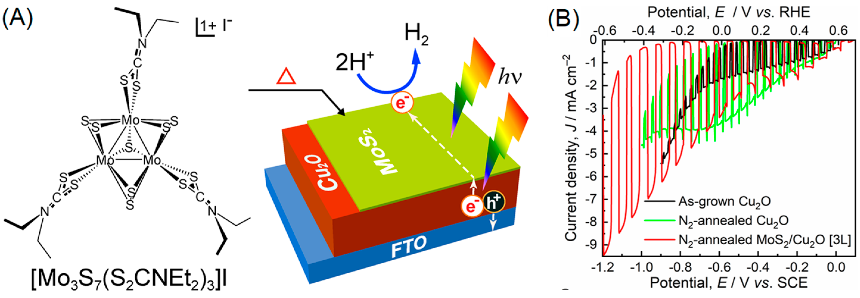
  24. Shinde, P.S.; Fontenot, P.R.; Donahue, J.P.; Waters, J.L.; Kung, P.; McNamara, L.E.; Hammer, N.I.; Gupta, A.; Pan, S. Synthesis of MoS2 from [Mo3S7(S2CNEt2)3]I for Enhancing Photoelectrochemical Performance and Stability of Cu2O Photocathode toward Efficient Solar Water Splitting. J. Mater. Chem. A 2018, 6, 9569–9582. [Google Scholar] [CrossRef]
  25. Merki, D.; Fierro, S.; Vrubel, H.; Hu, X.L. Amorphous Molybdenum Sulfide Films as Catalysts for Electrochemical Hydrogen Production in Water. Chem. Sci. 2011, 2, 1262–1267. [Google Scholar] [CrossRef]
  26. Vrubel, H.; Merki, D.; Hu, X. Hydrogen Evolution Catalyzed by MoS3 and MoS2 Particles. Energy Environ. Sci. 2012, 5, 6136–6144. [Google Scholar] [CrossRef]
  27. Lin, L.; Miao, N.; Wen, Y.; Zhang, S.; Ghosez, P.; Sun, Z.; Allwood, D.A. Sulfur-Depleted Monolayered Molybdenum Disulfide Nanocrystals for Superelectrochemical Hydrogen Evolution Reaction. ACS Nano 2016, 10, 8929–8937. [Google Scholar] [CrossRef] [PubMed]
  28. Xie, J.F.; Zhang, H.; Li, S.; Wang, R.X.; Sun, X.; Zhou, M.; Zhou, J.F.; Lou, X.W.; Xie, Y. Defect-Rich MoS2 Ultrathin Nanosheets with Additional Active Edge Sites for Enhanced Electrocatalytic Hydrogen Evolution. Adv. Mater. 2013, 25, 5807–5813. [Google Scholar] [CrossRef] [PubMed]
  29. Merki, D.; Vrubel, H.; Rovelli, L.; Fierro, S.; Hu, X. Fe, Co, and Ni Ions Promote the Catalytic Activity of Amorphous Molybdenum Sulfide Films for Hydrogen Evolution. Chem. Sci. 2012, 3, 2515–2525. [Google Scholar] [CrossRef]
  30. Roger, I.; Moca, R.; Miras, H.N.; Crawford, K.G.; Moran, D.A.J.; Ganin, A.Y.; Symes, M.D. The Direct Hydrothermal Deposition of Cobalt-Doped MoS2 onto Fluorine-Doped SnO2 Substrates for Catalysis of the Electrochemical Hydrogen Evolution Reaction. J. Mater. Chem. A 2017, 5, 1472–1480. [Google Scholar] [CrossRef]
  31. Gao, D.; Si, M.; Li, J.; Zhang, J.; Zhang, Z.; Yang, Z.; Xue, D. Ferromagnetism in Freestanding MoS2 Nanosheets. Nanoscale Res. Lett. 2013, 8, 129. [Google Scholar] [CrossRef]
  32. Li, G.; Zhang, D.; Qiao, Q.; Yu, Y.; Peterson, D.; Zafar, A.; Kumar, R.; Curtarolo, S.; Hunte, F.; Shannon, S.; et al. All the Catalytic Active Sites of MoS2 for Hydrogen Evolution. J. Am. Chem. Soc. 2016, 138, 16632–16638. [Google Scholar] [CrossRef] [PubMed]
  33. Gan, X.; Zhao, H.; Quan, X. Two-Dimensional MoS2: A Promising Building Block for Biosensors. Biosens. Bioelectron. 2017, 89, 56–71. [Google Scholar] [CrossRef] [PubMed]
  34. Chatterjee, S.; Sengupta, K.; Bandyopadhyay, S.; Dey, A. Ammonium Tetrathiomolybdate as a Novel Electrode Material for Convenient Tuning of the Kinetics of Electrochemical O2 Reduction by using Iron–Porphyrin Catalysts. J. Mater. Chem. A 2016, 4, 6819–6823. [Google Scholar] [CrossRef]
  35. Zheng, D.; Zhang, G.; Hou, Y.; Wang, X. Layering MoS2 on Soft Hollow g-C3N4 Nanostructures for Photocatalytic Hydrogen Evolution. Appl. Catal. A 2016, 521, 2–8. [Google Scholar] [CrossRef]
  36. Eda, G.; Yamaguchi, H.; Voiry, D.; Fujita, T.; Chen, M.; Chhowalla, M. Photoluminescence from Chemically Exfoliated MoS2. Nano Lett. 2011, 11, 5111–5116. [Google Scholar] [CrossRef] [PubMed]
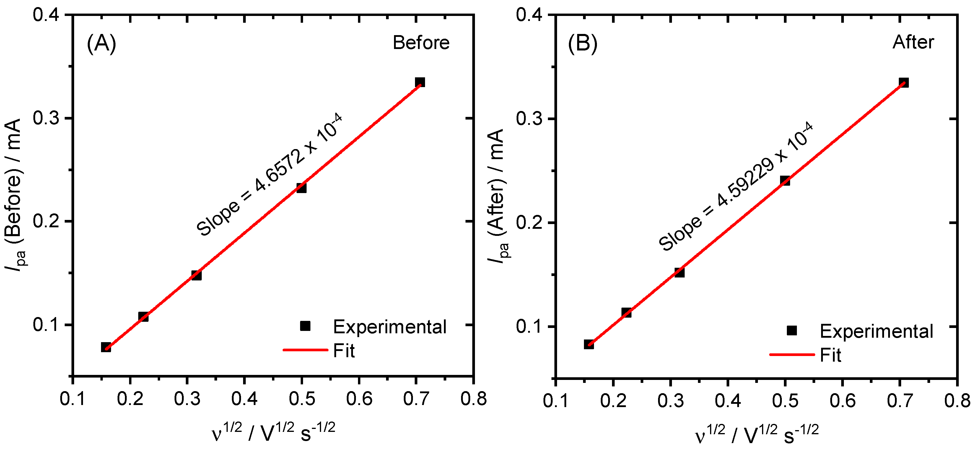
  37. Hamzah, I.H.; Manaf, A.A.; Sidek, O. A Study on Characteristic and Reliability of Fabricated Microfluidic Three Electrodes Sensor Based on Randle-Sevcik Equation. In Proceedings of the 2010 IEEE Asia Pacific Conference on Circuits and Systems, Kuala Lumpur, Malaysia, 6–9 December 2010; pp. 816–819. [Google Scholar]
Figure 1. (A) Schematic showing the formation of a proton reduction catalytic MoS2 layer on top of a p-type Cu2O via spin coating [Mo3S7(S2CNEt2)3]I and thermal annealing. Cu2O was electrodeposited on fluorine-doped tin oxide (FTO) substrate; and (B) photocurrent responses of as-grown Cu2O, N2-annealed Cu2O, and N2-annealed MoS2-modified Cu2O photocathodes under intermittent light illumination in 0.5 M Na2SO4 (pH ~6.7); light: simulated 1 sun (100 mW cm−2). Reproduced with permission from [24], published by Royal Society of Chemistry, 2018.
Inorganics 07 00079 g001
Figure 2. Polarization curves of MoS2/FTO electrodes fabricated at 450 °C in a nitrogen environment. Scan rate: 50 mV s–1; electrolyte: 0.5 M H2SO4. Reproduced with permission from [24], published by Royal Society of Chemistry, 2018.
Inorganics 07 00079 g002
Figure 3. Schematic of [Mo3S7(S2CNMe2)3]+ monolayer-coated Au electrode surface for the catalytic proton reduction reaction.
Inorganics 07 00079 g003
Figure 4. (A) Survey XPS spectrum for [Mo3S7(S2CNEt2)3]I in DMF coated on Au/ITO; Inset shows the elemental compositions for S and Mo with their respective binding energy (B.E.) positions, full width at half maximum (FWHM) values, areas, and the atomic percentages (at %); and (B) high resolution deconvoluted XPS spectra of Mo 3d, S 2p and (C) 1s lines for [Mo3S7(S2CNEt2)3]I in DMF coated on Au/ITO.
Inorganics 07 00079 g004
Figure 5. Cyclic voltammetry (CV) curves at different scan rates for surface coverage analysis of Au disc electrode before (A) and after (B) coating with [Mo3S7(S2CNMe2)3]I in THF. Electrolyte: 1 mM K3Fe(CN)6 in 0.1 M KNO3.
Inorganics 07 00079 g005
Figure 6. The plots of anodic peak current (Ipa) versus ν−1/2 (derived from Figure 5) before (A) and after (B) assembling MoSx monolayer on Au disc.
Inorganics 07 00079 g006
Figure 7. CV curves recorded for bare and MoSx-coated Au/ITO electrodes prepared using [Mo3S7(S2CNMe2)3]I in THF by spin coating and overnight immersion methods. Electrolyte: 0.5 M H2SO4. The inset of the figure shows the zoom-in features of Au oxidation near 0.2 V vs. RHE.
Inorganics 07 00079 g007
Figure 8. (A) CV curves of various MoS2 precursor derivatives in 0.5 M H2SO4; and (B) Tafel plot of MoSx derivatives derived from Figure 8A.
Inorganics 07 00079 g008
Figure 9. RRDE responses (rotation speed: 4900 rpm) for bare GC, Au/GC, 0.1 mM MoSx/GC, and 0.1 mM MoSx/Au/GC electrodes. The inset shows the schematic diagram of GC-Pt RRDE with deposition of Au and/or MoSx/Au on GC and side view depicting reduction-oxidation reactions on the respective electrodes. Scan rate: 50 mV s−1; electrolyte: 0.5 M H2SO4 degassed using N2.
Inorganics 07 00079 g009

