Review

Fluorolytic Sol–Gel Synthesis of Nanometal Fluorides: Accessing New Materials for Optical Applications

Humboldt-Universität zu Berlin, Department of Chemistry, Brook-Taylor-Str. 2, D-12489 Berlin, Germany
*
Author to whom correspondence should be addressed.
Inorganics 2018, 6(4), 128; https://doi.org/10.3390/inorganics6040128
Submission received: 20 September 2018 / Revised: 20 November 2018 / Accepted: 28 November 2018 / Published: 3 December 2018
(This article belongs to the Special Issue Metal Fluorides)

Abstract

:
The potential of fluorolytic sol–gel synthesis for a wide variety of applications in the field of optical materials is reviewed. Based on the fluorolytic sol–gel synthesis of nanometal fluorides, sols of complex fluorometalates have become available that exhibit superior optical properties over known classical binary metal fluorides as, for instance, magnesium fluoride, calcium fluoride, or strontium fluoride, respectively. The synthesis of transparent sols of magnesium fluoroaluminates of the general composition MgxAlFy, and fluoroperovskites, [K1−xNax]MgF3, is reported. Antireflective coatings fabricated from MgF2, CaF2, MgxAlFy, and [K1−xNax]MgF3 sols and their relevant properties are comprehensively described. Especially the heavier alkaline earth metal fluorides and the fluorperovskites crystallizing in a cubic crystal structure are excellent hosts for rare earth (RE) metals. Thus, the second chapter reflects the synthesis approach and the properties of luminescent systems based on RE-doped alkaline earth metal fluorides and [K1−xNax]MgF3 phases.

1. Introduction

Nanomaterials chemistry has become an extremely important area of research over the past 40 years. Although numerous nanomaterials have already accessed applications in several areas, the new scientific and industrial revolution driven by the advances in nanomaterials science is still at the beginning.
Over the past decades, many new synthesis techniques have been explored, giving access to the fascinating world of nanomaterials with exciting chemical and physical properties. Many different synthesis routes have been developed, resulting in nanomaterials of distinctly distinguished properties. Among several different synthesis approaches, sol–gel synthesis certainly is one of the most powerful synthesis routes in terms of the variety of technical applications. The most prominent and mostly introduced one is doubtlessly the aqueous sol–gel synthesis route, which was pushed mainly by the development of silica, and still is attracting the interest of thousands of chemists and materials scientists worldwide. In a very simple way, this sol–gel synthesis can be described by two consecutive reaction steps, the first one being the hydrolysis of a metal–alkoxide group, followed in the second step by condensation among OH and/or OR groups. Finally, a highly distorted, three-dimensional network of M–O–M bridges is formed, and if performed under appropriate conditions, nanoscopic metal oxides are accessible.
However, new non-aqueous sol–gel approaches like ALD (atomic layer deposition) have recently been explored, which allow either the synthesis of novel materials, or in many cases, give access to applications which are not at all possible via hydrolytic sol–gel routes. One of these new non-hydrolytic sol–gel approaches is the so-called fluorolytic sol–gel synthesis that gives access towards novel nanosized metal fluorides [1]. Due to their diverse functionalities, nanometal fluorides have gained tremendous attraction as materials for many applications over the last few years [2,3,4,5,6]. Since the first review about nanofluorides was published in 2006 [2], several further reviews and book chapters have appeared, reflecting specific aspects of the chemistry and materials science of nanometal fluorides [7,8,9,10,11,12,13,14,15,16,17]. Components of solar batteries [18], precursors for laser and scintillation ceramics [19,20], white light sources [21,22], biomedical materials [23,24,25,26,27], or catalysis [8,28,29] are just a few examples for potential applications of nanometal fluorides. Thus, nanometal fluorides have recently gained increasing interest as materials for many different applications. However, among all these different fields of applications, the optical properties of metal fluorides are of outstanding interest because, due to the strong electronegativity of the fluoride anions, metal fluorides usually exhibit large band gaps. As a result of this, several metal fluorides have a significant lower refractive index than the respective metal oxides. As can be predicted from the data for some selected metal fluorides, even the optical window is significantly wider for metal fluorides compared to the respective metal oxides (cf. Table 1). That is, metal fluorides are transparent for hard UV irradiation, but also for longer wave numbers in the IR region. Due to their low refractive indices, several metal fluorides are extremely interesting candidates to be used as antireflective (AR) materials for coating, e.g., glass windows, screens made of PMMA or polycarbonate, eye glasses.
Note, for this kind of application, it is not only the refractive index that is important, but also solubility, stability against water, melting point (temperature stability), or hardness (scratch resistance).
Another highly important area of optical applications is luminescent materials for up- and down-conversion (see Reference [3]). Rare earth (RE) metal compounds usually show luminescent properties; however, in pure form they tend for radiation free relaxation due to quenching effects if they are situated too near to each other. In order to circumvent these problems, suitable host materials have to be used in order to separate the RE metals by doping them into the host lattices. Excellent host systems for this purpose are metal fluorides in a cubic structure, like the heavier alkaline earth metal fluorides or fluorperovskites MIMIIF3.
In spite of the great importance of metal fluoride based optical materials, the focus of this paper is outlining new synthesis approaches to address new application opportunities, which have for the first time become available, based on homodispersed nanoscopic metal fluoride sols that can be obtained in an excellent way, via fluorolytic sol–gel synthesis.

2. Nanometal Fluoride Particles and Their Application as Optical Materials

The widely used techniques for the preparation of nanometal fluorides are flame pyrolysis, microwave-assisted solvothermal synthesis, classical precipitation methods from aqueous solutions, and microemulsion routes [3]. The first sol–gel-type method for the synthesis of nanometal fluorides is the trifluoracetate route, developed mainly by Fushihara’s group in the late nineties [30]. However, it is just an indirect route; as a first step, a reaction between a suitable metal precursor with trifluoracetic acid results in the formation of metal trifluoroacetate sols (Equation (1)).
M(OR)x + x CF3COOH → M(OOCCF3)x + x HOR
Such sols can be either further processed for coating or to obtain powders after solvent evaporation. Following calcination of coatings or powders eventually results in the formation of metal fluorides due to thermal decomposition of the metal trifluoroacetates (Equation (2)).
M(OOCCF3)x → nano-MFx + 1/x(CF3CO)2O + CO2 + CO
The drawbacks of this route are sometimes incomplete thermal decomposition, hazardous gaseous byproducts, and the limitation that not all metals form fluoroacetates, nor decompose towards metal fluorides, instead forming metal oxides. Despite all the mentioned drawbacks, this synthesis route was the first highly potent sol–gel-based synthesis approach towards nanometal fluoride materials. A very efficient alternative and direct synthesis method for the preparation of nanometal fluorides is the so-called fluorolytic sol–gel method developed in our group using anhydrous HF as a fluorinating agent [1,7,31]. For convenient handling and dosing, HF can be dissolved in organic solvents like alcohols or ethers, and such HF solutions can easily be reacted with solutions of suitable metal precursors (alkoxides, acetates, chlorides, etc.) preferentially dissolved in the same solvent as HF. Equation (3) displays the general reaction route:
M(OR)x + x HFsolv → nano-MFx + x HOR
Depending on the metal precursors and the HF content used, different nanofluorides can be prepared:
  • Binary fluorides (MgF2, CaF2), e.g., for antireflective coatings;
  • Complex fluorides (MgxAlFy), fluorperovskites (MIMIIF3) for antireflective coatings and hosts for rare earth metal (relevant for luminescent materials);
  • Hosts for up and down conversion (CaF2, SrF2, BaF2, complex lanthanide fluorides);
  • Other applications—composites, dental materials, wood protection, etc.
The main features of this powerful fluorolytic sol–gel synthesis were recently reviewed comprehensively [12,32,33], giving deeper insight into the mechanistic details of the synthesis conditions, role of precursors and solvents, etc. The stepwise replacement of the precursor alkoxide groups by fluoride ions was thoroughly studied based on Solid State Nuclear Magnetic Resonance Spectroscopy (MAS-NMR), X-ray Diffraction (XRD), Wide-Angle X-ray Scattering (WAXS), and Small-Angle X-ray Scattering (SAXS) investigations and important data on topological and rheological parameters of these materials were presented. For deeper insight into all these mechanistic aspects, we refer to the cited review articles. Here, we restrict the focus on several synthesis approaches relevant for obtaining fluoride materials for optical applications.

2.1. Binary Fluorides for Antireflective Coatings

2.1.1. Magnesium Fluoride

Optical materials with a low refractive index (<1.30) are very attractive for the development of antireflective coatings. The Nikon Corporation published in 2008 a method for the preparation of thin films containing MgF2 which is reinforced by a SiO2 binder [34]. After a sol–gel reaction of magnesium acetate and HF in methanol, the crystallinity of the MgF2 particles was low and the surface of the resulting coating was unstable. By heating the MgF2 solution in an autoclave, the crystallinity increased and the resulting films had a high porosity with nanopores between the particles (n = 1.20@550 nm). Due to the porous structure of the MgF2 films, the film strength had to be improved by a SiO2 binder. The combined MgF2–SiO2 coating is wipe- and environment-resistant, but no information is given about the resistance against water.
Because of the high porosity of the MgF2–AR coatings associated with a poor adhesion of the resulting films, the application by dip-coating to cover large areas (windows in buildings) is not an industrial standard so far. It is only possible to sputter thin MgF2 films on small substrates, such as lenses. This is the reason only a few publications exist worldwide about this topic, although increasing research activities can be observed recently.
In 2017, Karthik et al. reported on high performance broad band antireflective mesoporous MgF2 coatings for solar applications [35]. The MgF2 nanoparticles were synthesized from MgCl2 and HF/water. After the reaction, the mixture was transferred to an autoclave and heated up to 200 °C for several hours up to a few days. The nanoparticles obtained after a duration of 1 h were still mesoporous. The resulting coatings showed the best optical properties (100% transmittance and 0% reflectance, n = 1.16@600 nm). After weather and thermal stability tests, no change in average transmittance was observed, but no wipe tests were carried out. Hence, the stability of the coatings on the substrates is doubtful. Another drawback is that the high HCl content in the resulting sol causes corrosion and environmental concerns, thus making them inappropriate for industrial applications. All these approaches have the drawback of being time- and cost-intensive due to the necessary autoclave treatment making up-scaling illusory.
Already in 2012, the synthesis and properties of MgF2 sols obtained from MgCl2 via the new fluorolytic sol–gel synthesis were reported and comprehensively discussed [36]. The advantage of this approach is that without any further treatment, water-clear ethanolic MgF2 sols were obtained, which were directly used for the dip-coating of glass plates. For the preparation of antireflective coatings with a low refractive index in the visible range, AR layers built up by respective nanoparticles which form open pore structures are needed. For that reason, at first, the MgF2 particles in the sols were thoroughly investigated by dynamic light scattering, 19F solid state NMR, and XRD.
As can be seen in Figure 1, the particle size distribution of MgF2 is monodisperse, with a maximum at 8 nm. By thermal treatment, the particle size distribution increases to 60 nm, apparently by Ostwald ripening or coalescence, but in general, such sols are appropriate for the coating of different substrates, for example, glasses (windows, vitrines, lenses) or polymers (displays etc.).
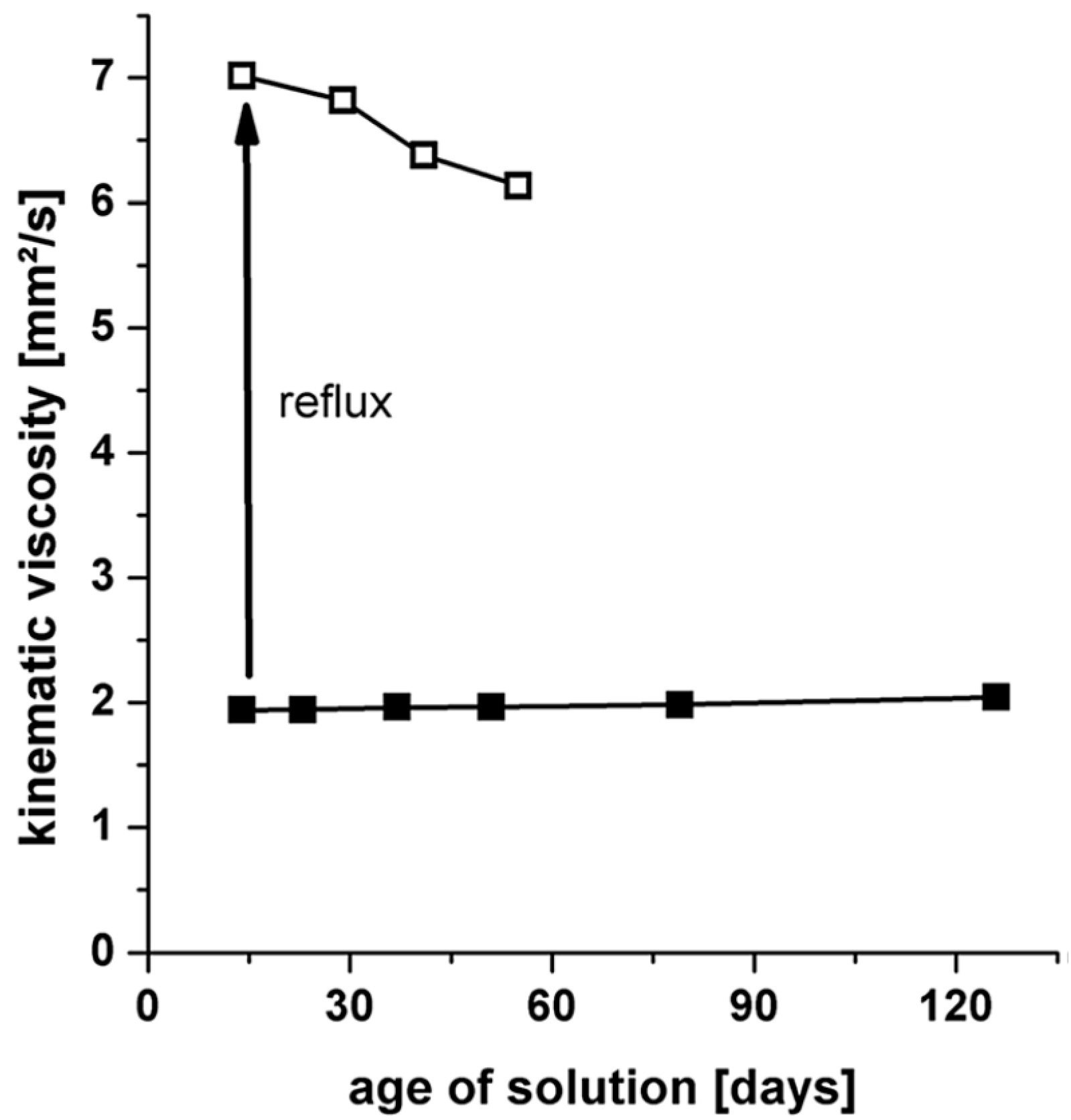
The long-term stability of MgF2 sols is crucial for the coating process. Nanoparticles, after sol–gel synthesis, tend toward gelation or agglomeration. To control the stability, the change of viscosity of the sols over a time of 120 days was measured (Figure 2). Only a minimal increase (0.01 mm2·s−1) over this time was observed, meaning these sols are very stable. After the thermal treatment, the viscosity was significantly higher. It seems that the sol system may be altered by introduction of thermal energy.
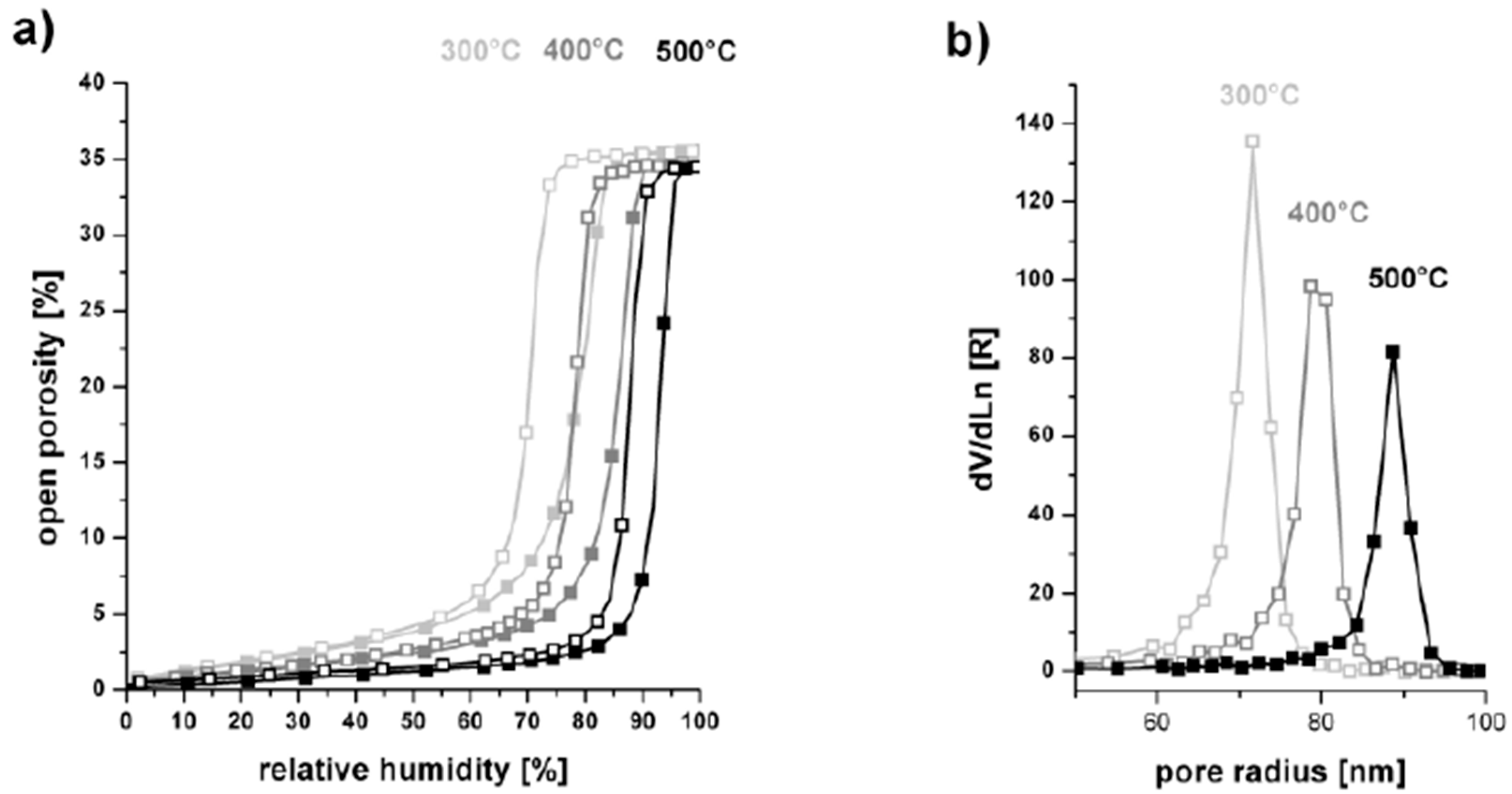
The MgF2 films coated on soda lime glass were investigated in terms of film porosity, optical properties, and mechanical stability. Figure 3 shows the adsorption–desorption isotherms of several films depending on the treatment temperature, determined by ellipsometric porosimetry (EP). It can be seen that the overall porosity of the MgF2 films is approximately 35% independent from the treatment temperature. Obviously, already after 300 °C, the organic part of the gel film (solvent) is completely removed and the inorganic part (MgF2) remains on the substrate. However, the pore radius is increased due to the growth of crystalline grains at higher temperature.
With a minimum reflectance of 0.35% at 600 nm, the coated MgF2 films showed excellent antireflective properties. An increase of the treatment temperature led only to a slight reduction of this reflection, which corresponds to the open pore structure determined.
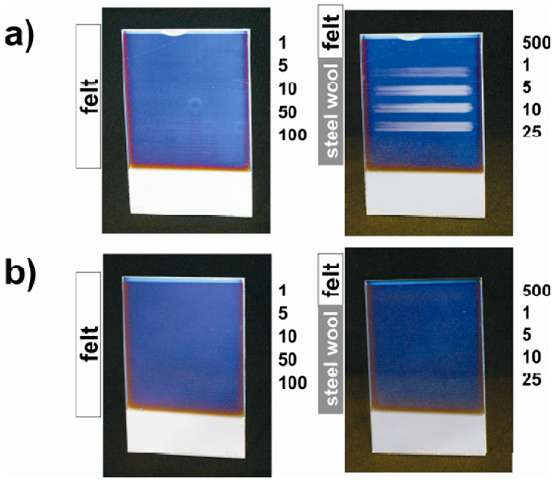
The mechanical stability, which is crucial for any practical application, but was not presented for AR layers reported inside the publications cited before, was tested with the Crockmeter test using felt or steel wool stamps (force 4 N) (Figure 4). On borosilicate glass, even after 500 abrasion cycles with felt and 25 cycles with steel wool (hardness 0000), no scratches are visible. The MgF2 films exhibited an appreciable stability under mechanical stress. As can be seen, the MgF2 antireflective coatings from the raw material MgCl2 possess excellent optical and mechanical properties. Unfortunately, however, these sols are inappropriate for industrial application due to the high amount of HCl which is formed during the sol synthesis. This HCl may cause high corrosion of the industrial coating plants, and thus is rather of fundamental than real interest.
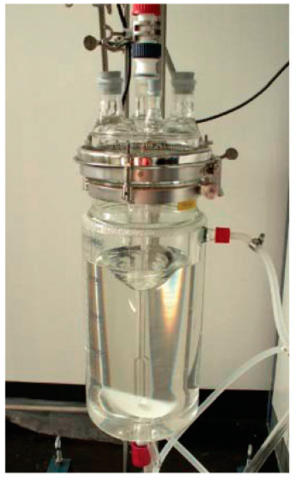
A few years later, Scheurell et al. [37,38] reported on the optimization of the fluorolytic sol–gel synthesis of MgF2 for a large-scale process, starting from magnesium acetate tetrahydrate. After a mild dehydration (100 °C, under vacuum) of the acetate tetrahydrate to the nearly water-free acetate and reaction with water-free HF, it was possible to obtain clear MgF2 sols (Figure 5).
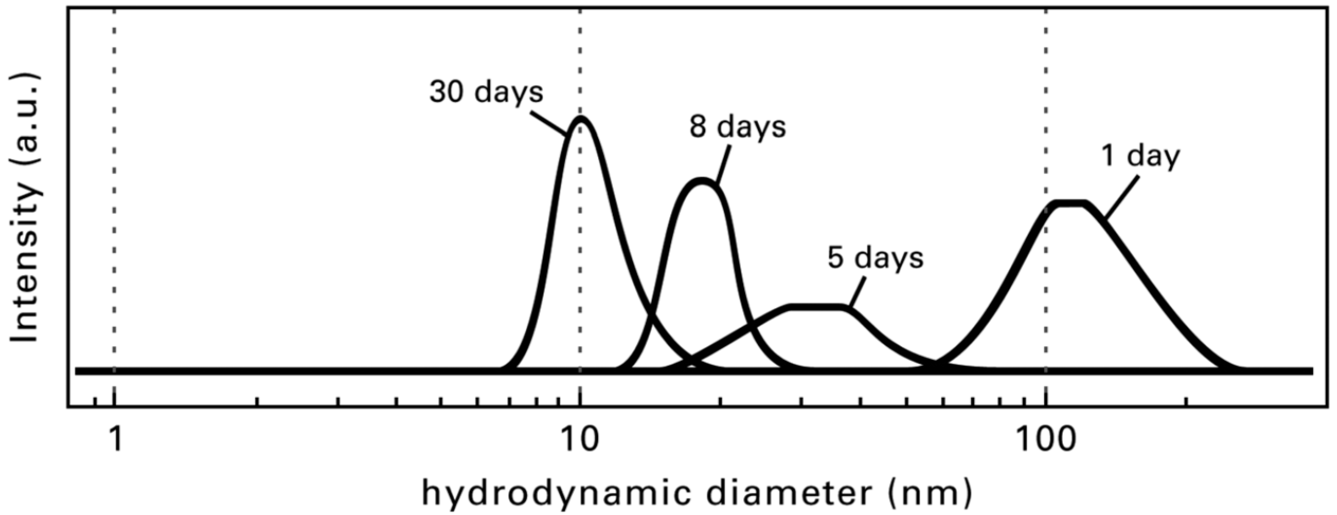
Directly after the reaction of the magnesium acetate with HF, the formed MgF2 sols are turbid because of the interaction of the very active MgF2 particles. Depending on the concentration or dimension of the synthesis approach, clear sols are only obtained after several hours, days, or sometimes even weeks. Figure 6 demonstrates the change in particle size distribution depending on the sol age, followed by Dynamic Light Scattering (DLS). Obviously, the fluorolytic sol–gel synthesis of metal fluoride nanoparticles occurs according to the model described by Bogush and Zukovsky [39]. This means that initially, larger aggregates/agglomerates of small particles are formed, which decompose slowly with time. For a faster deagglomeration of the sol particles, additives such as Al(OiPr)3 or tetrametyl orthosilicate (TMOS) and trifluoroactic acid (TFA) were applied in order to accelerate the decomposition of these agglomerates. The viscosity of the resulting sols is low (2 mm2·s−1) and nearly constant over a time of 130 days.
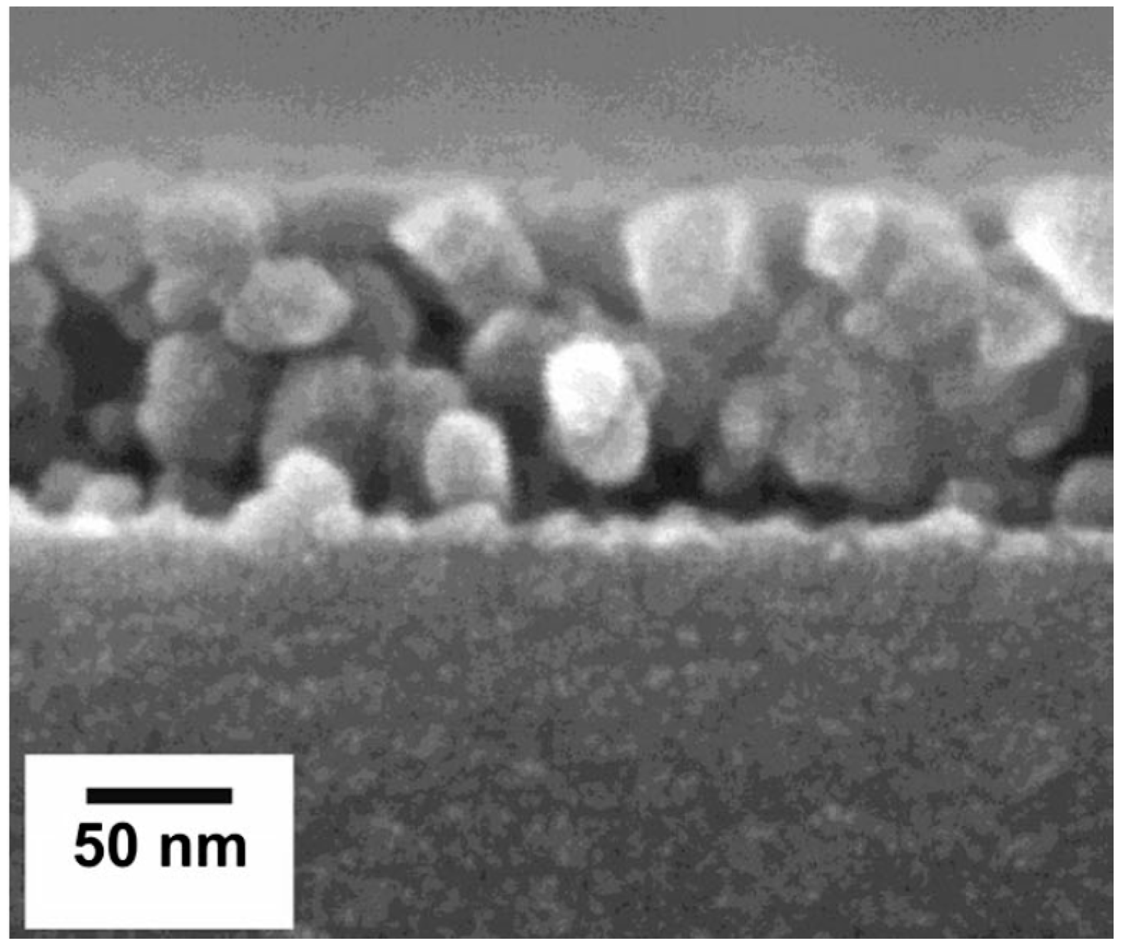
The film morphology of the MgF2 coating from Mg(OAc)2 as a precursor after a thermal treatment at 500 °C is shown in Figure 7. The particle size is approximately 30 nm. In contrast to the MgF2 films from MgCl2 (see above), the porosity of the films from Mg(OAc)2 is only 19%. Obviously, the microstructure of the porous MgF2 films strongly depends on the precursor used in the fluorolytic sol–gel synthesis process.
The optical properties and mechanical stability are very good, but there is still a disadvantage when Mg(OAc)2 is used as a precursor for the synthesis. That is, the acetic acid formed during the synthesis reacts with the solvent ethanol to form acetic ester and water. As with many other sol–gel routes, water makes the sols unstable on a long-time scale, resulting in increasing viscosity and gelation after a few months. Thus, for industrial application, this is an obvious drawback.
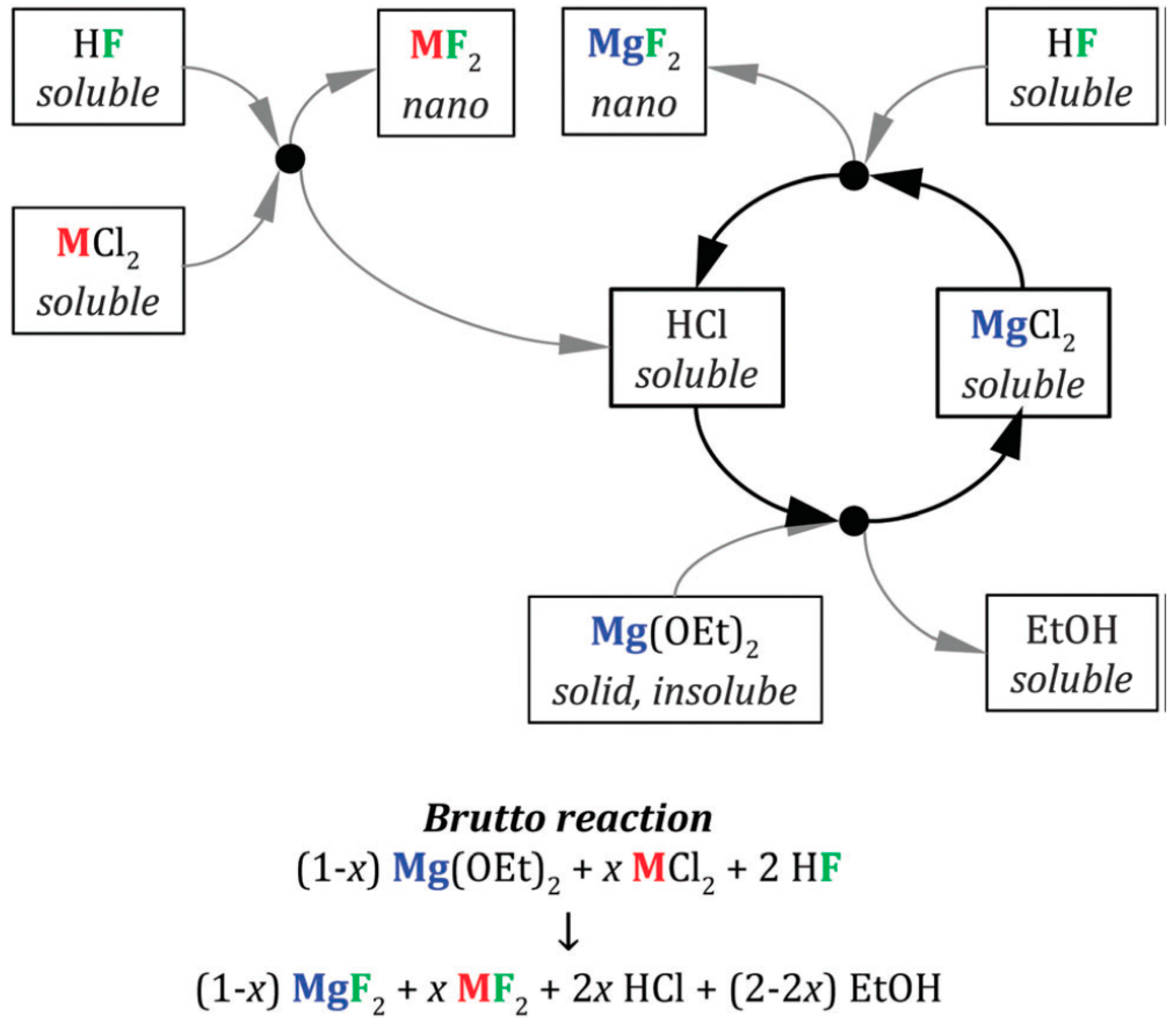
Of course, similar to the classical sol–gel synthesis to form SiO2, for fluorolytic sol–gel synthesis to MgF2, alkoxides are also suitable as precursor materials. In the case of the magnesium methanolate, starting with the reaction of magnesium metal in methanol, the synthesis is very easy and after several hours, water-clear sols in methanol can be obtained. Unfortunately, for a large-scale synthesis process and subsequent dip-coating of substrates, the solvent methanol cannot be used because of its extreme toxicity. Moreover, the reaction of neat magnesium with methanol forms hydrogen gas, which might raise safety issues. Magnesium ethoxide is insoluble in alcohols and no homogeneous reaction can be performed to form MgF2. Under no circumstances were clear sols obtained. A new synthesis was developed [40], starting from Mg(OEt)2 and MCl2 (M = Mg or Ca) in ethanol.
The chloride quickly dissolves in ethanol and reacts with HF, thus forming HCl in addition to MgF2. The hydrogen chloride formed can then react with unreacted Mg(OEt)2, forming MgCl2 and ethanol, and consequently, a catalytic cycle is established. Using this way, water-clear sols can be obtained with just a small amount of HCl that is acceptable for industrial applications. Figure 8 represents a schematic overview of the reactions. The optical properties (reflectance below 1%) of the resulting MgF2 coatings are excellent and as good as the thin films from MgCl2 or Mg(OAc)2. However, the HCl content is much smaller than in the pure MgCl2 system, but the stability of the sols is significantly better than in the acetate system—no ester formation is possible. Using this reaction cycle, a new reaction path way developed to upscale this one-pot reaction to a batch of 5 L. Through the addition of chloride additives (AlCl3, CaCl2, LaCl3, LiCl, MgCl2, SrCl2, SnCl2), the corresponding layers showed enhanced stability towards mechanical abrasion (steel wool 00, 25 cycles, 4 N) and improved durability against water [41].
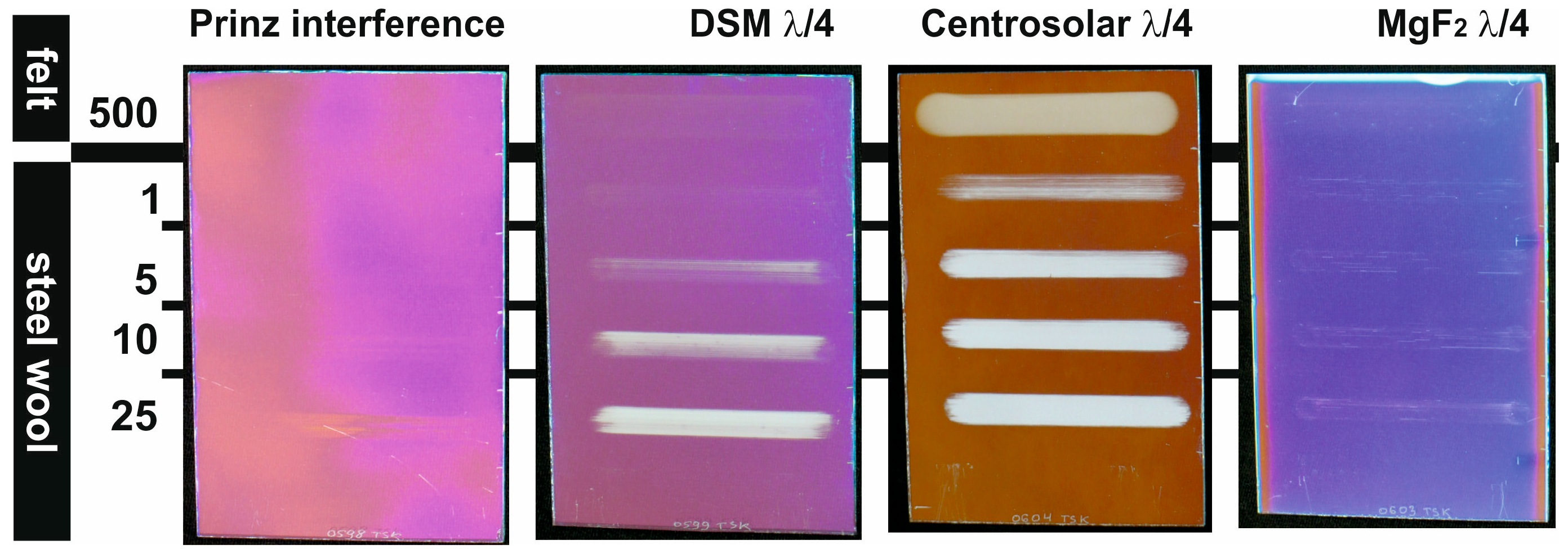
A comparison of antireflective coatings of commercial products with the new MgF2 λ/4 coatings is reported in Reference [42]. The commercial AR products are SiO2 films from Centrosolar (Fürth, Germany), 3-layer interference-type AR coatings from Prinz Optics (Stromberg, Germany), and DSM coating solutions based on polymer templates (DSM, Heerlen, The Netherland).
As can be seen from Table 2, the optical properties (transmittance 97.5–99.7%) of the different antireflective coatings are comparable. The highest transmittance was achieved with λ/4 films from Centrosolar, apparently due to the high open porosity (50.2%) inside the layers. However, amongst all these porous λ/4 systems, only the novel MgF2 films exhibited superior mechanical film stability compared to their SiO2 counterparts under investigation (Figure 9). In the Crockmeter tests, using felt (500 cycles) and steel wool (max. 25 cycles), the MgF2 films showed only very few scratches.

2.1.2. Calcium Fluoride

The refractive index of crystalline CaF2 is 1.44 [43]. Similar to MgF2, CaF2 with a sufficient porosity is also a promising candidate for λ/4 coatings to decrease the reflection of the incident light of glass. An advantage of CaF2 against MgF2 is the very low solubility in water, which could be an important factor in view of the chemical resistance of antireflective coatings towards environmental conditions [44]. Until now, CaF2 films were deposited by physical or chemical vapor deposition techniques. In 2007, Pilvi et al. [45] reported on the atomic layer deposition (ALD) of CaF2 on SiO2/Si at 300 °C with a low impurity level. The resulting CaF2 films exhibited a refractive index of 1.43, but the transmission decreased with decreasing wavelength in the UV range.
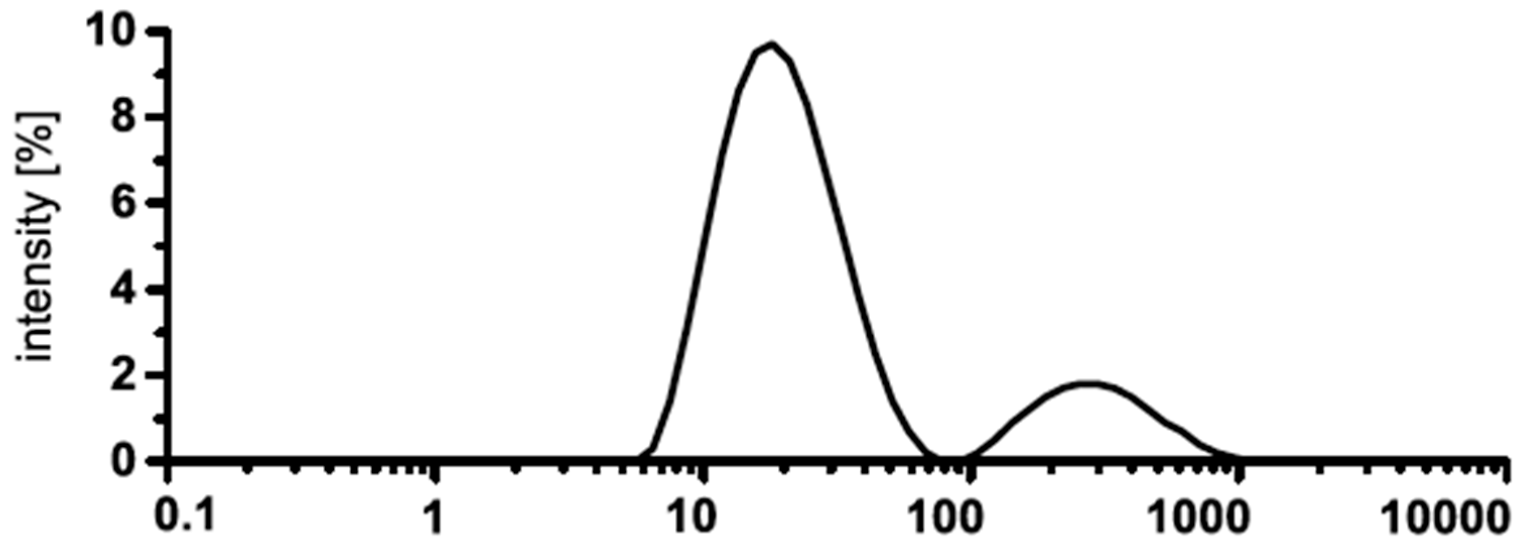
In 2015, Rehmer et al. [46] reported for the first time the application of nanoscopic CaF2 via the fluorolytic sol–gel synthesis route for antireflective coatings. The synthesis of transparent CaF2 sol starting from calcium alkoxides was not successful because of the insolubility of the alkoxides in the alcohols used. Calcium acetate suspended in mixtures of ethanol and acetic acid provides transparent CaF2 sols, but the stability of these sols is very poor. After a few days, a gel is formed due to the esterification of the acetic acid with ethanol forming water. The best suitable starting material to form CaF2 via sol–gel synthesis is CaCl2. First, the resulting sol is not fully transparent, but opaque. However, after the addition of 5 mol % TMOS as a stabilization agent, a water-clear transparent CaF2 sol is formed. The particle size distribution of the CaF2 sol is given in Figure 10. The intensity weighted distribution shows two classes of particles with a mean particle size of 20 nm.
Another remarkable precursor material for the synthesis of CaF2 nanoparticles is calcium lactate pentahydrate [47]. The solubility of the lactate in ethanol is very good and it needs only a short time after reaction with HF to obtain clear CaF2 sols. A comparison of the optical data between CaF2 films on float glass prepared from CaCl2 and Ca(OLac)2·5H2O is shown in Figure 11. After the annealing process (500 °C, 15 min), the porosity of the CaF2 films from the lactate precursor is much higher (48%) due to the high organic amount of the precursor. Therefore, the reflectance of this coating is nearly zero and the refractive index around 1.26.
Unfortunately, the mechanical stability of the coating from the MgF2 sol obtained from a magnesium lactate is very poor. Already after one cycle of felt treatment, the CaF2 film was completely destroyed. By contrast, the surface of the CaF2 coating from CaCl2 was only barely damaged, even after 100 cycles with steel wool. The difference between the two precursors in optical and mechanical properties can be rationalized based on the lactic acid formed when starting with the lactate, which (i) has a high boiling point and (ii) tends to polymerize even more in order to maintain organics inside the layers that thermally decompose at higher annealing temperatures only, thus creating many pores due to the blowing effect of the decomposition products (mainly CO2 and water). Starting with inorganic precursors, on the other hand, no volatile products are formed at higher annealing temperature; thus, the densification process is not counteraffected, resulting in mechanically evidently stronger films.

2.2. Complex Fluorides for Antireflective Coatings

Magnesium Fluoro Aluminates—MgxAlFy and [K1−xNax]MgF3

Antireflective films from binary fluorides, such as MgF2 and CaF2, exhibit excellent optical properties and are resistant against abrasion and scratches. At this time, coated glasses with such films can be used for lenses, vitrines, and internal windows. A remaining drawback is still water resistance, meaning stability towards environmental influences for any outdoor application of such coatings. It is still under debate whether this water sensibility arises from dissolution of the MgF2 coatings or is rather an effect caused by the lowering the MgF2–particle–particle attraction inside the MgF2 layer resulting in a kind of delamination. We do believe in the second hypothesis. Several complex fluorides, especially magnesium fluoro aluminates, exhibit equally or even lower refractive indices, but fortunately, are insoluble in water [32].
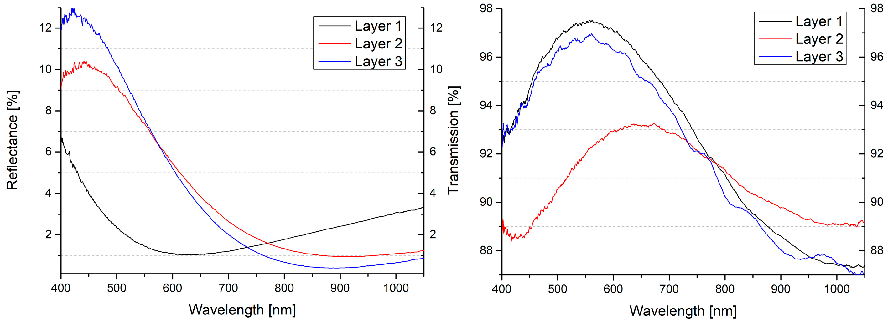
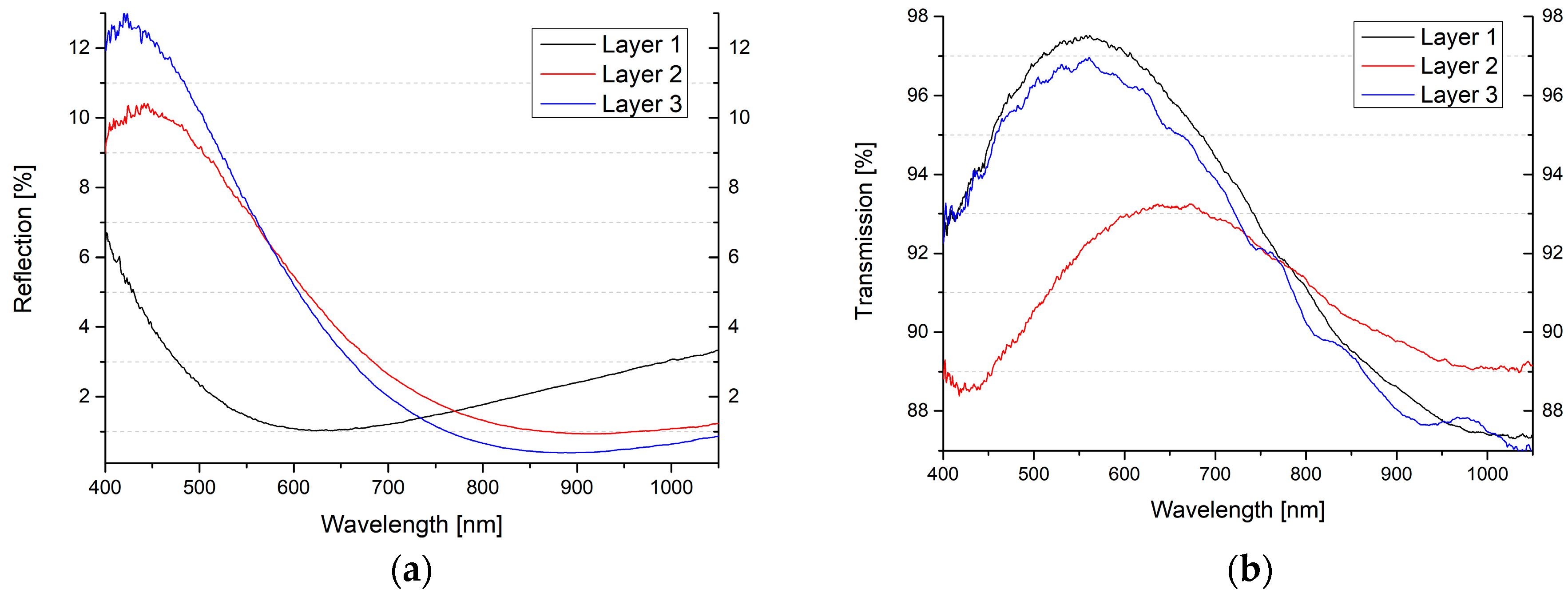
To investigate such compounds to be used for optical films, synthesis conditions were discovered giving direct access to water-clear sols of these complex metal fluoride sols. Note, so far there are no reports on the synthesis of transparent fluorometalate sols containing homodispersed fluoride nanoparticles via any other synthesis route. Finally, synthesis protocols for different magnesium fluoroaluminates (MgAlF5, Mg2AlF7 and MgAl2F8) and perovskite type fluoride compounds via the fluorolytic sol–gel approach were successful. After synthesis, in all cases, colorless and clear colloidal dispersions were obtained [48]. With 19F MAS NMR, signal shifting by thermal impacts due to the evaporation of oxygen-containing groups (remaining OR groups from the precursors) was observed. Moreover, the thermal impact finally led to the decomposition of the complexes into the pure fluorides MgF2 and AlF3 above 500 °C.
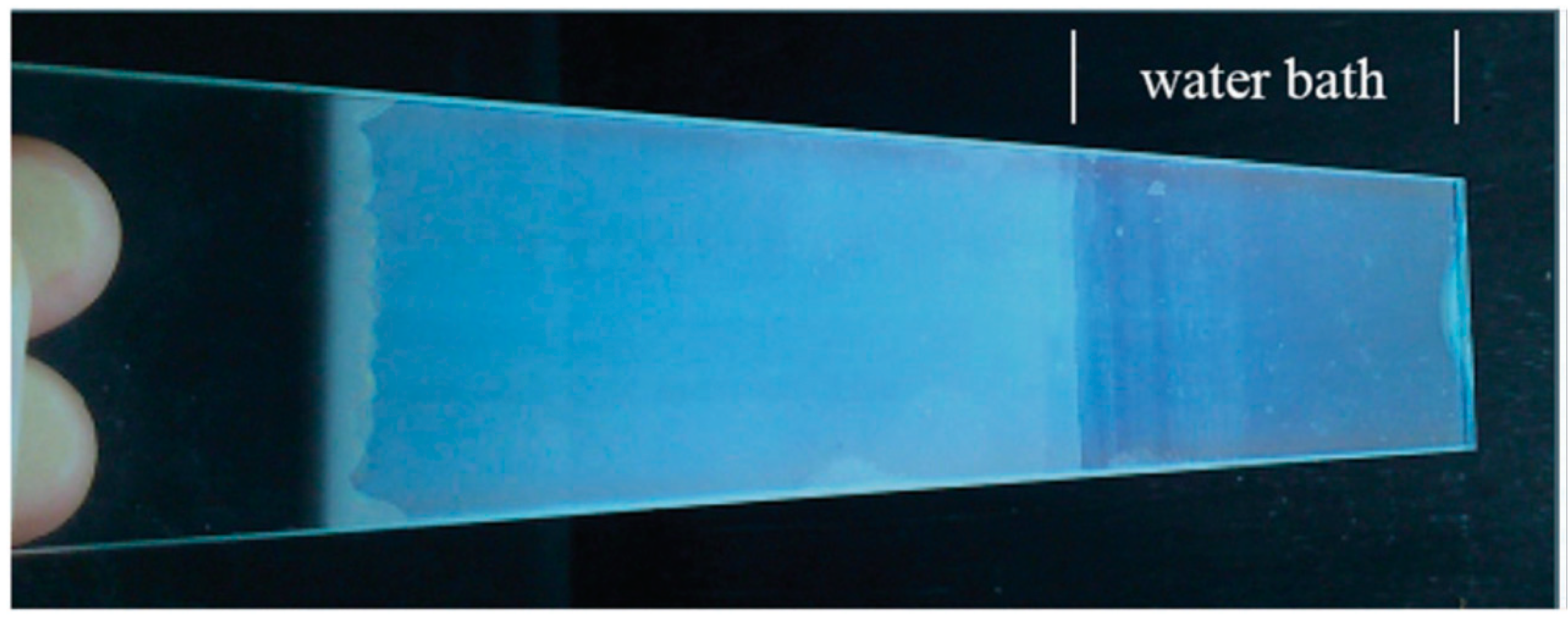
As can be seen from Figure 12, the antireflective behavior of the films built up by complex fluorides is excellent, e.g., reflections below 1% and in the case of Mg2AlF7, even below 0.5%. Unfortunately, the transmissions of all layers are not on the highest level for antireflective coatings (93–97%). Obviously, due to the higher crystallinity of the complex fluorides, the films are not totally clear and absorbance and scattering can take place. Expectedly, the stability of these layers towards water is excitingly high (see Figure 13).
After thermal densification at 450 °C for 15 min, the coated glasses were put into a bath with de-ionized water. Fourteen days later, the glasses were removed from the water bath and dried at room temperature. All coatings were scratch-resistant, meaning they could not be rubbed off from the substrates with a tissue. Thus, the connectivity between the substrate (glass) and the films (complex fluorides) was very strong. Note, respective MgF2 layers can easily be rubbed off after 5 to 8 days only.
Another group of complex fluorides are the perovskite like complexes (MIMIIF3). Perovskites are nearly insoluble compounds and their refractive indices are in a low range (KMgF3: 1.404 and NaMgF3: 1.364). These characteristics make them interesting candidates as AR layer materials, although they have not been reported so far for such applications. This is obviously due to the fact that gas phase deposition is complicated, and sols of such materials were not available so far. However, Schütz et al. [49] very recently reported the synthesis and characterization of perovskite mixed phases ([K1−xNax]MgF3) as coating material for the production of antireflective films on glass substrates. In the case of alkali-containing fluoride sols, only one clear sol (KMgF3) was formed. It was synthesized at 0 °C with TMOS as a stabilization additive. Based on dynamic light scattering investigations, a mean particle size diameter of 70 nm in a monodispersed distribution was determined. After dip-coating on float glass and thermal densifying at 450 °C, the reflectance was with 0.15% in an optimal range for antireflective materials. In the same manner as the magnesium fluoroaluminates (see above), the transmission is not very high (96.1%). By means of structural analysis methods, such as XRD and solid-state NMR spectroscopy, an increase of crystallinity of the perovskite phases after thermal treatment at 450 °C could be evidenced. Obviously, this might be the reason for the lower transmittance of the thin films on glass substrates after the densifying.
To sum up, the fluorolytic sol–gel synthesis has been proven to be a kind of universal direct synthesis approach to water-clear binary metal fluoride, but even complex metal fluorides as well, which can be directly used for manufacturing antireflective coatings via the dip-coating technique. No intermediate treatment, e.g., in autoclaves, is necessary. Additionally, since this synthesis method can easily be scaled up, large-scale industrial application is generally possible.

2.3. Up and Down Conversion Materials

CaF2, SrF2 and BaF2 as Hosts for Rare Earth Metals

An interesting field in the area of optical materials is the field of luminescent nanoparticles. Luminescent nanoscale materials exhibit the potential for innovative applications, like medical and biological labels [50], displays [51], fluorescent ceramics [52], and solar cells [53]. Alkali earth metal fluorides are very suitable hosts for rare earth doping because of their cubic structure, their high transparency in a broad spectral range, and low photon energy. A lot of complex synthesis methods for the preparation of such systems exist: Thermally assisted polyol-mediated precipitation synthesis [54], thermally induced precipitation synthesis in water-free methanol [55], and incorporation of Tb3+ in transparent glass–ceramic containing CaF2 nanocrystals [56]. Numerous publications, review articles, or book chapters have appeared over the recent years, covering this wide field of research [4].
Fortunately, fluorolytic sol–gel synthesis is a simple single-step method that also gives direct access to rare earth doped fluoride containing nanoparticles. It seems that practically all rare earth metal fluorides can be directly incorporated into the alkaline earth metal (Ca, Sr, Ba), thus proving again fluorolytic sol–gel synthesis as a very convenient universal synthesis for nanometal fluorides. Here, we exemplarily describe some selected examples just to show how effective, but simple this synthesis approach is. In 2014, Ritter et al. [57] reported on the incorporation of Eu3+ and Tb3+ into nanoscale CaF2 using the fluorolytic sol–gel method with calcium lactate and europium- or terbium acetate as precursors. Equation (4) shows a short rationalization of the reaction path.
(1 − x) Ca(OR‘)2 + x Ln(OR’’)3 + (2 + x) HF → Ca1−xLnxF2+x + (2 − 2x) R’OH + 3x·R’’OH
OR’ = Lactate; OR’’ = Acetate, x = 0…0.1
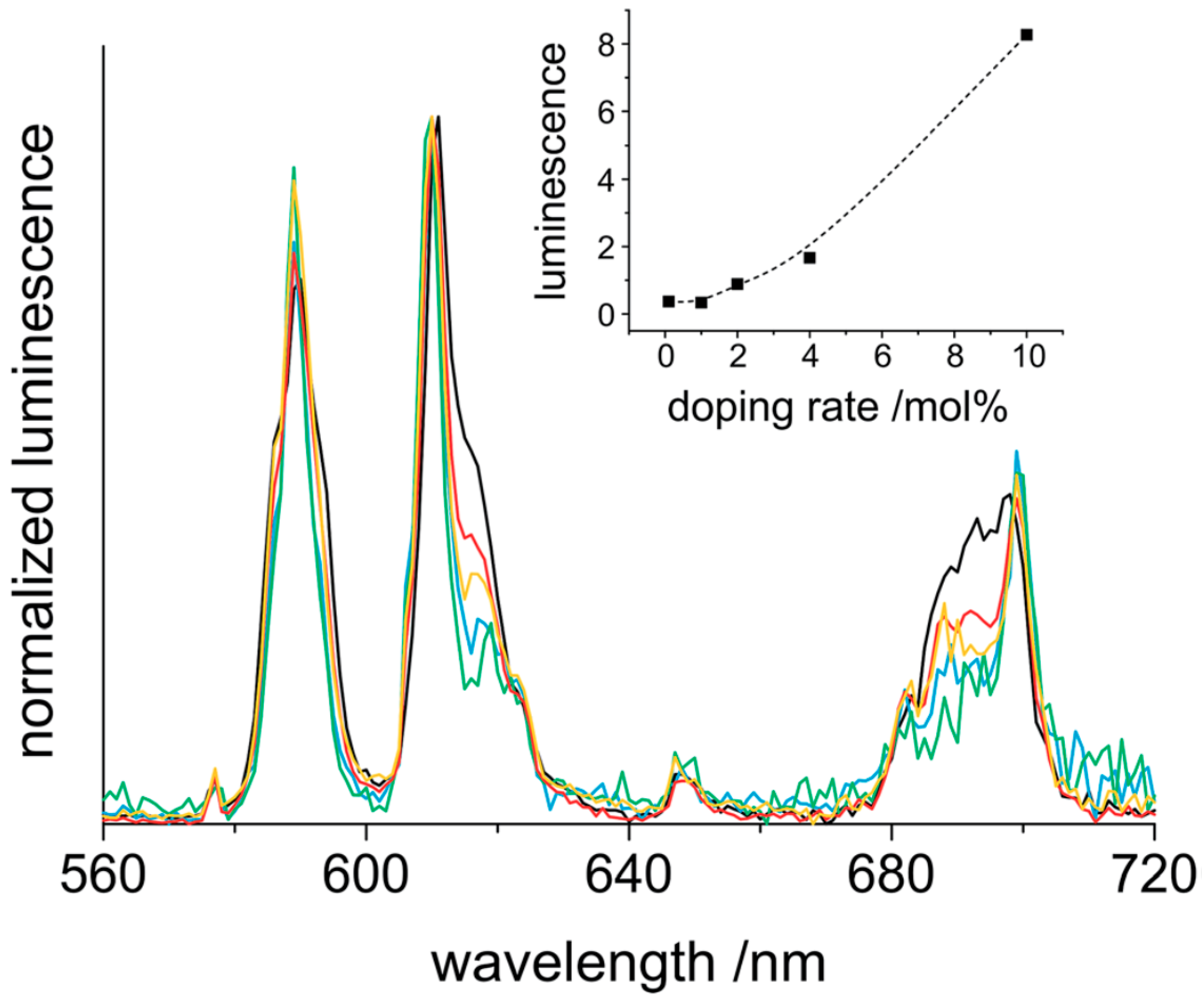
The clear sols of CaF2:Eu in methanol with different dopant concentrations show a bright red luminescence upon excitation at 393 nm. This leads to several emission bands in the visible spectral range. These emissions fit very well to the transitions 5D07F0 (578 nm), 5D07F1 (590 nm), 5D07F2 (611 nm), 5D07F3 (647 nm), and 5D07F4 (698 nm).
With the exception of 5D0/7F0, which is located in the yellow range, all the other emissions are detectable in the red spectral region. This fact and the low intensity of the yellow band result in an overall reddish appearance. The bands with the highest intensities match to 5D07F1 and 5D07F2 (Figure 14).
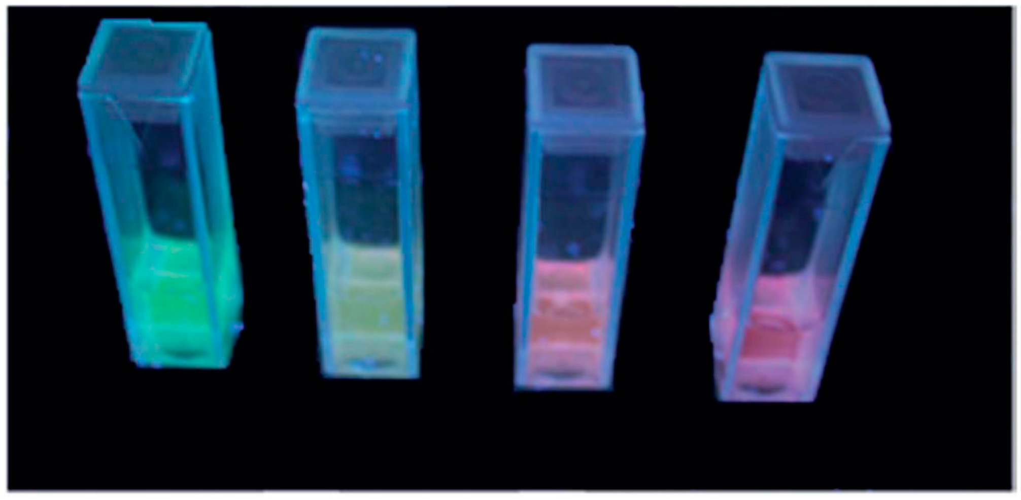
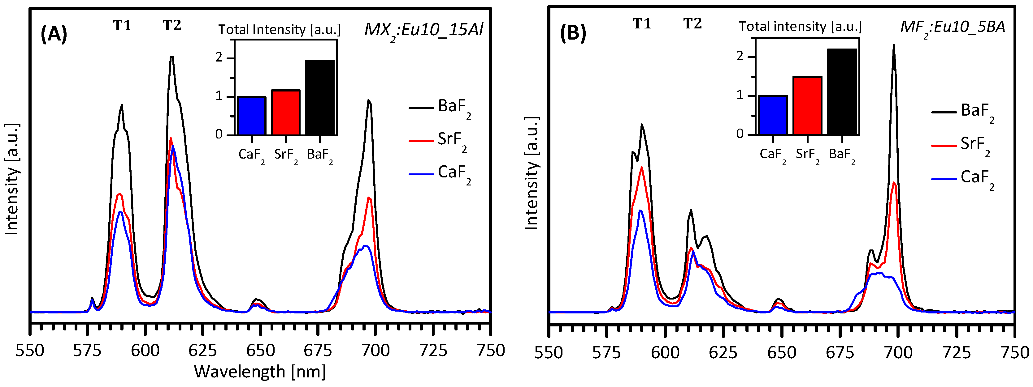
Excitation of the sols at 366 nm with a handheld UV-lamp reveals an intense fluorescence, yet a different color for all the four cases (Figure 15). In all cases described here, CaF2 was the host for the rare earth metal dopants. By use of other alkali earth metal fluorides as hosts, such as SrF2 or BaF2 and mixtures of them, a broad variation of luminescence properties was obtained [58]. Therefore, high luminescence intensities are achieved without significant quenching effects, even for a 30% rare earth content and more (Figure 16).
This is a new and promising result and a big step forward towards a higher light efficiency. Luminescence intensities, lifetimes, and quantum yields of the rare earth ions steadily increase from CaF2 via SrF2 to BaF2.
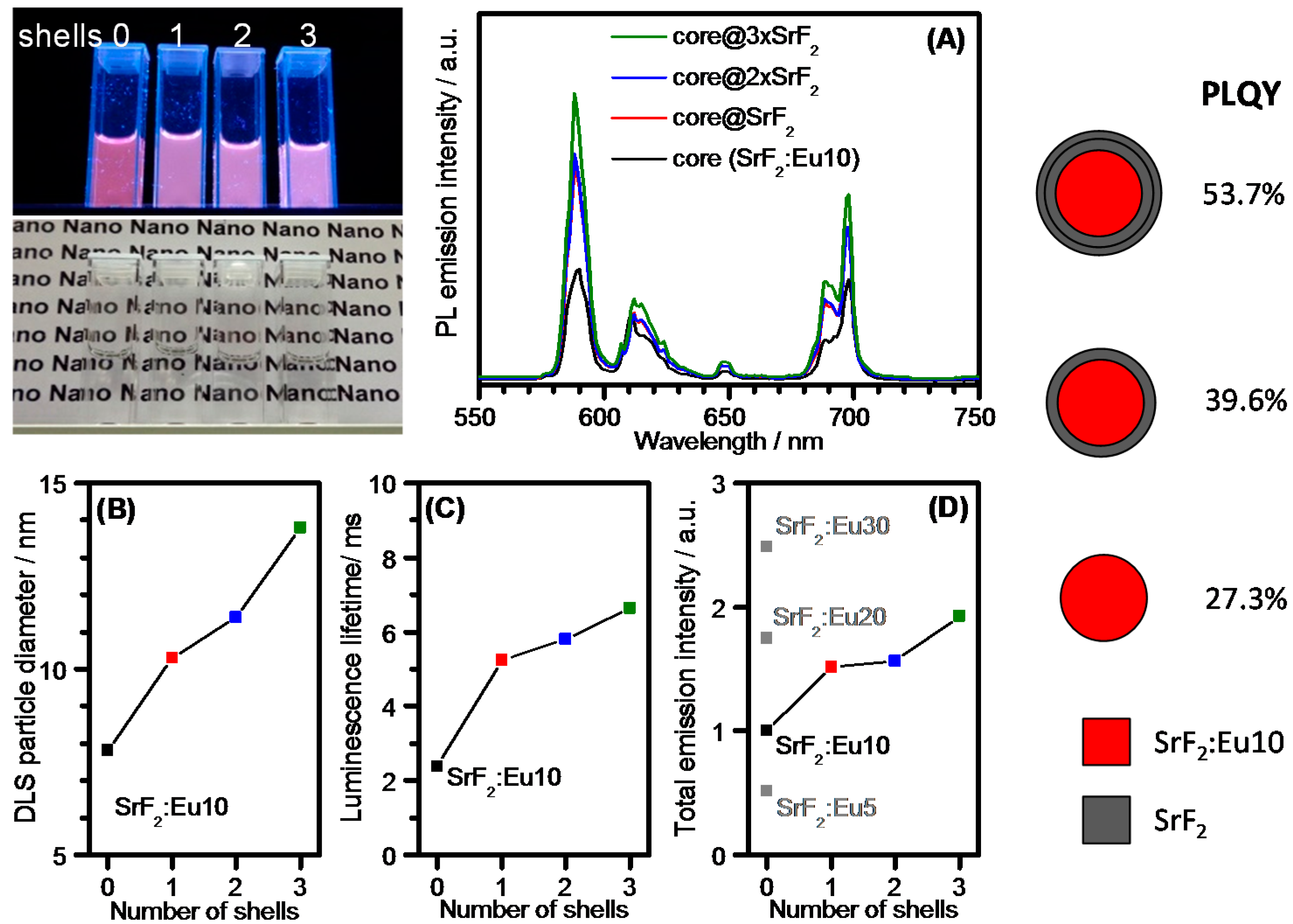
In the past years, core–shell structured nanoparticles possessing an inorganic core surrounded by an inorganic shell have been invented to reduce radiation-free relaxations, to improve luminescent light output, to increase quantum efficiency, and to solve the problems from undesired energy transfers in multirare-earth-doped systems, which result in a divergent color impression. Using the fluorolytic sol–gel route, in 2017, core–shell structured metal fluoride nanoparticles were prepared for the first time [59]. This method enables the synthesis of large amounts (kilogram) of nanostructured core–shell particles in one batch at room temperature. The remarkable behavior of the prepared nanoparticles in the case of SrF2:Eu10@n×SrF2 (n = 0–3) is given in Figure 17.
As can be seen in Figure 17, the particle diameter increases with the number of shells from 8 to 14 nm. In the same manner, the luminescence lifetime and total emission intensity increase with every additional SrF2 shell, whereby the greatest impact of luminescent intensity was found for the first shell.
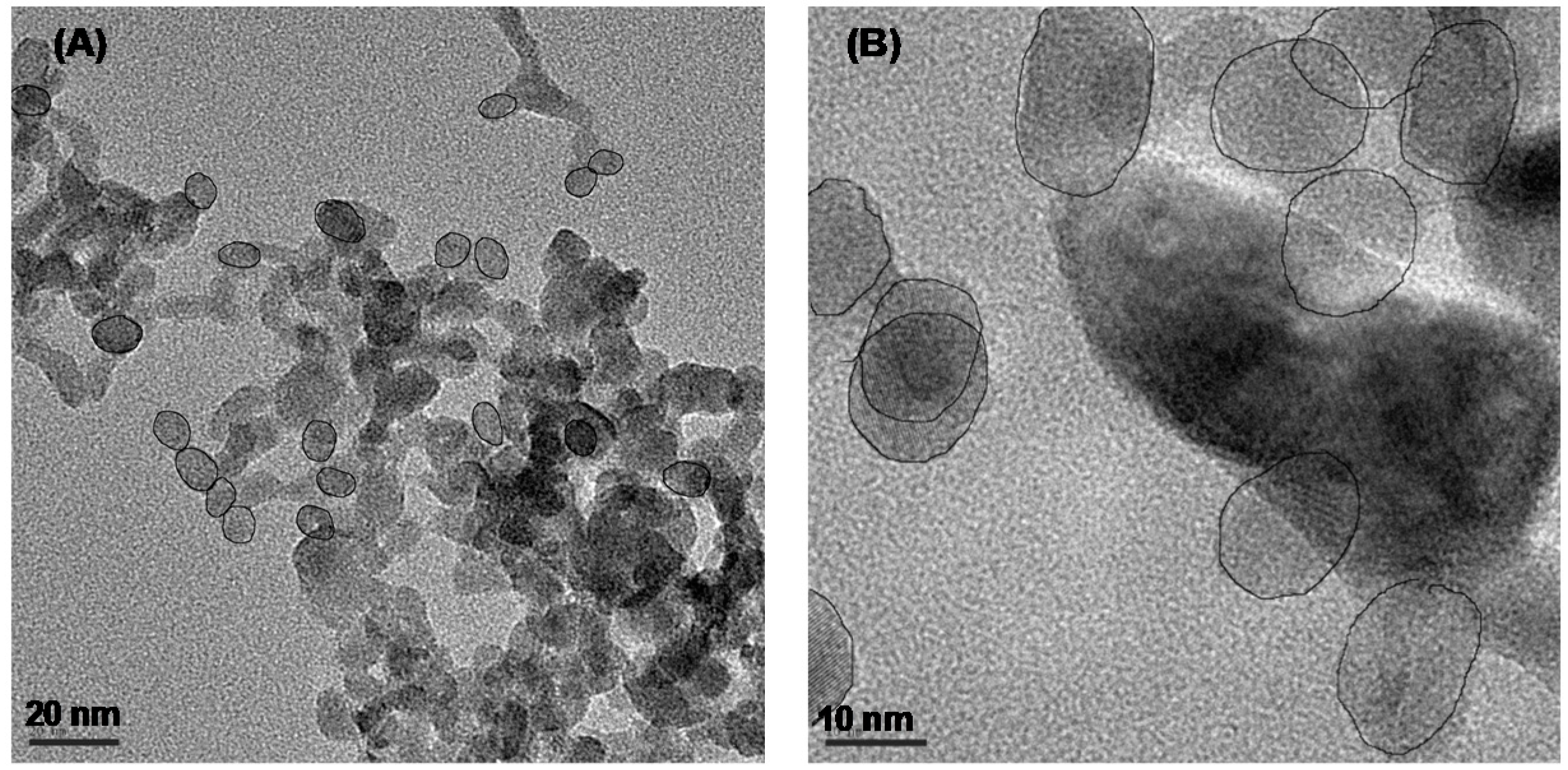
The improving luminescence properties with every additional shell are a clear evidence of the successive formation of a core–shell system. TEM images of SrF2:Eu10 core particles and SrF2:Eu10@3×SrF2 core–shell particles directly prove the increase of particle size (Figure 18).
As per the description in the part-magnesium fluoro aluminates (see above), fluorolytic sol–gel synthesis has been also successfully applied for the synthesis of nanoscaled, homodispersed complex calcium metal fluoride sols (CaAlF5, Ca2AlF7, LiMgAlF6) using CaCl2, MgCl2, LiOMe, and Al(OiPr)3 as metal precursors, which were reacted with anhydrous HF in ethanol. All complex metal fluoride sols showed long-time stability and transparency, even after months. These complex metal fluorides recently gained enormous interest as hosts for fluorescent materials due to the suitable sizes of the ionic radii of alkaline earth cations. In addition, they exhibit high ionic strength, hardness, and good isolation behavior and are stable over a wide temperature range [60].

2.4. Composites

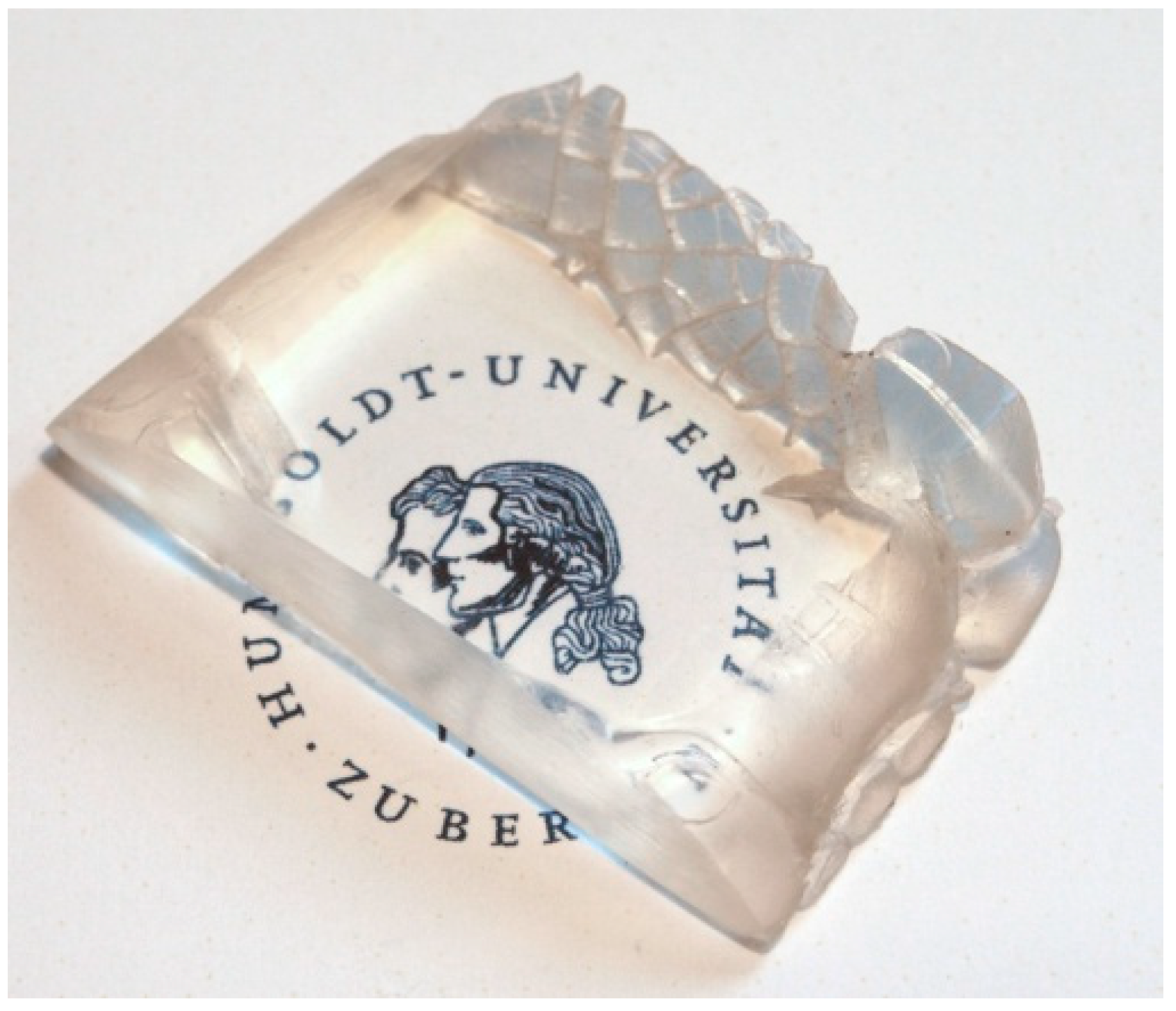
Inorganic fillers are able to enhance the performance of organic polymers in terms of thermal or mechanical behavior associated with electrical or thermal conductivity. Furthermore, because of the special optical properties of MgF2, the resulting composites (polymer and inorganic filler material) are totally transparent (Figure 19) [61,62].
The synthesized MgF2 sols via the fluorolytic sol–gel method, stabilized by trifluoroacetic acid, were successfully mixed with acrylate monomers and after polymerization, volume composite or thin films with filler contents up to 40 wt % can be formed (Figure 20).
In the case of the polymer poly(1,4-BDDMA), an incorporation of MgF2 nanoparticles from 10 to 40 wt % leads to a significantly reduction of the refractive index from 1.47 to 1.43. Thus, for polymers that need a precisely tuned low refractive index, e.g., as in the case of cladding materials for glass fibers, this offers new opportunities for further progress in this regard.

3. Summary and Outlook

This article has focused on the potential arising from the recently developed fluorolytic sol–gel synthesis, which gives direct access to homidispersed nanoscopic metal fluoride materials. The big advantage of the fluorolytic sol–gel approach is the direct access of water-clear sols containing homodispersed metal fluoride nanoparticles. The application of anhydrous HF prevents the agglomeration of NPs and gelation. All the other routes that are based on aqueous HF solutions have to be post-treated in autoclaves, followed by several separation steps, thus being extremely time-demanding and costly and far away from industrial-scale application. Fluorolytic sol–gel synthesis gives not only water-clear sols for manufacturing AR coatings, but also allows very simple, up-scalable synthesis of all imaginable rare earth doped alkaline earth metal (Ca, Sr, Ba) fluoride systems that are of high interest as up- and down-converting materials. Moreover, modified in the right manner, these homodispersed metal fluoride NPs can be used to down tune the refractive index of several organic polymers resulting in transparent metal fluoride–polymer composites.
However, there are several other applications away from those reflected here, since the manufacturing of metal fluoride sols allows coating for other purposes too. Thus, sodium fluoroaluminate near the eutectic composition of the AlF3–NaF system (Na1.3AlF4.3) is used under the trade name “Nocolock” by Solvay for the welding of an aluminum-based heat exchanger in automobiles. Moreover, KZnF3 has become increasingly important over the past years as an anticorrosion reagent for aluminum passivation in order to replace copper by aluminum in outdoor air conditioners. In both cases, the application of nanoscopic fluorometalate soles instead of commonly used pastes of micrometers big particles in organic binders offers significantly improved application technologies and drastically improved efficiency. It is worth mentioning that sols could even be used to coat pipes etc. from the inner side, which is impossible based on highly viscous pastes.
Metal fluoride coatings are also of interest in the case of corrosion protection against aggressive fluoride-based compounds, e.g., hydrogen fluoride or even fluorine gas. Repeated coatings of, e.g., transparent MgF2 layers that are thermally densified after each single coating step can effectively protect the coated layers of, e.g., glass or diverse metal surfaces.
An extremely important field of application arises from the low solubility of, e.g., CaF2 or SrF2 for dental applications. Sols of just several nanometers small MF2 particles can be used to easily introduce these MF2–NPs into caries lesions, creating a kind of depot therein this way. Due to the very low solubility of, e.g., CaF2, a controlled release of fluoride and calcium ions over time takes place exactly at that place where these ions are needed for re-mineralization. Thus, an extensive, repeated supply of soluble fluorides which is still state-of-the-art becomes superfluous. Even the introduction of such MF2–NPs into polymeric dental materials is possible and offers further advantages for the development of new dental materials.
All these applications of metal fluorides are only possible if homodispersed nanoparticles are accessible, and those can be obtained via the fluorolytic sol–gel approach as presented here.

Funding

The authors thank the research training network GRK 1582/2 “Fluorine as a Key Element” of DFG (Deutsche Forschungsgemeinschaft) for funding. This project was partly also funded by the German Federal Ministry of Economics and Technology (Grant 03ET1235C).

Conflicts of Interest

The authors declare no conflict of interest.

References

  1. Kemnitz, E.; Gross, U.; Rüdiger, S.; Shekar, C.S. Amorphous Metal Fluorides with Extraordinary High Surface Areas. Angew. Chem. Int. Ed. 2003, 42, 4251–4254. [Google Scholar] [CrossRef] [PubMed]
  2. Kuznetzov, S.V.; Osiko, V.V.; Tkatchenko, E.A.; Fedorov, P.P. Inorganic nanofluorides and related nanocomposites. Russ. Chem. Rev. 2006, 75, 1065–1082. [Google Scholar] [CrossRef]
  3. Fedorov, P.P.; Luginina, A.A.; Kuznetsov, S.V.; Osiko, V.V. Nanofluorides. J. Fluorine Chem. 2011, 132, 1012–1039. [Google Scholar] [CrossRef]
  4. Fedorov, P.P.; Kuznetsov, S.V.; Osiko, V.V. Photonic. In Electronic Properties of Fluoride Materials; Tressaud, A., Poeppelmeier, K., Eds.; Elsevier: Amsterdam, The Netherlands, 2016; pp. 7–31. [Google Scholar]
  5. Feng, W.; Sun, L.-D.; Zhang, Y.W.; Yan, C.-H. Synthesis and assembly of rare earth nanostructures directed by the principle of coordination chemistry in solution-based process. Coord. Chem. Rev. 2010, 254, 1038–1053. [Google Scholar] [CrossRef]
  6. Li, C.; Lin, J. Rare earth fluoride nano-/microcrystals: Synthesis, surface modification and application. Mater. Chem. 2010, 20, 6831–6847. [Google Scholar] [CrossRef]
  7. Rüdiger, S.; Gross, U.; Kemnitz, E. Non-aqueous sol–gel synthesis of nano-structured metal fluorides. J. Fluorine Chem. 2007, 128, 353–368. [Google Scholar] [CrossRef]
  8. Rüdiger, S.; Kemnitz, E. The fluorolytic sol–gel route to metal fluorides—A versatile process opening a variety of application fields. Dalton Trans. 2008, 9, 1117–1127. [Google Scholar] [CrossRef] [PubMed]
  9. Kemnitz, E.; Rüdiger, S. Alain Tressaud. In Functionalized Inorganic Fluorides; Wiley: Hoboken, NJ, USA, 2010; pp. 69–97. [Google Scholar]
  10. Kemnitz, E.; Wuttke, S.; Coman, S.M. Tailor-Made MgF2-Based Catalysts by Sol–Gel Synthesis. Eur. J. Inorg. Chem. 2011, 2011, 4773–4794. [Google Scholar] [CrossRef]
  11. Kemnitz, E. Nanoscale metal fluorides: A new class of heterogeneous catalysts. Catal. Sci. Technol. 2015, 5, 786–806. [Google Scholar] [CrossRef]
  12. Kemnitz, E.; Noack, J. The non-aqueous fluorolytic sol–gel synthesis of nanoscaled metal fluorides. Dalton Trans. 2015, 44, 19411. [Google Scholar] [CrossRef]
  13. Kemnitz, E. Handbook of Sol-Gel Science and Technology; Klein, L., Aparicio, M., Jitianu, A., Eds.; Springer: Cham, Switzerland, 2018. [Google Scholar]
  14. Kemnitz, E.; Coman, S. New Materials for Catalytic Applications; Elsevier: Amsterdam, The Netherlands, 2016; pp. 133–187. [Google Scholar]
  15. Krahl, T.; Kemnitz, E. Aluminium fluoride—The strongest solid Lewis acid: Structure and reactivity. Catal. Sci. Technol. 2017, 7, 773–796. [Google Scholar] [CrossRef]
  16. Lucier, B.E.G.; Johnston, K.E.; Arnold, D.C.; Lemyre, J.-L.; Beaupre, A.; Blanchette, M.; Ritcey, A.M.; Schurko, R.W. Comprehensive Solid-State Characterization of Rare Earth Fluoride Nanoparticles. J. Phys. Chem. C 2014, 118, 1213–1228. [Google Scholar] [CrossRef]
  17. Naccache, R.; Yu, Q.; Capobianco, J.A. The Fluoride Host: Nucleation, Growth, and Upconversion of Lanthanide-Doped Nanoparticles. Adv. Opt. Mater. 2015, 3, 482–509. [Google Scholar] [CrossRef]
  18. Huang, X.; Han, S.; Huang, W.; Lin, X. Enhancing solar cell efficiency: The search for luminescent materials as spectral converters. Chem. Soc. Rev. 2012, 42, 173–201. [Google Scholar] [CrossRef] [PubMed]
  19. Basiev, T.T.; Doroshenko, M.E.; Fedorov, P.P.; Konyushkin, V.A.; Kuznetsov, S.V.; Osiko, V.V.; Akchurin, M.S. Efficient laser based on CaF2–SrF2–YbF3 nanoceramics. Opt. Lett. 2008, 33, 521–523. [Google Scholar] [CrossRef]
  20. Aballea, P.; Suganuma, A.; Druon, F.; Hostalrich, J.; Georges, P.; Gredin, P.; Mortier, M. Laser performance of diode-pumped Yb:CaF2 optical ceramics synthesized using an energy-efficient process. Optica 2015, 2, 288–291. [Google Scholar] [CrossRef]
  21. Yang, L.W.; Han, H.L.; Zhang, Y.Y.; Zhong, J.X. White emission by frequency up-conversion in Yb3+-Ho3+-Tm3+ triply doped hexagonal NaYF4 nanorods. J. Phys. Chem. 2009, 133, 18995–18999. [Google Scholar] [CrossRef]
  22. Méndez-Ramos, J.; Yanes, A.C.; Santana-Alonso, A.; del-Castillo, J. Highly efficient up-conversion and bright white light in RE co-doped KYF4 nanocrystals in sol–gel silica matrix. Chem. Phys. Lett. 2013, 555, 196–201. [Google Scholar] [CrossRef]
  23. Wang, F.; Deng, R.; Wang, J.; Wang, Q.; Han, Y.; Zhu, H.; Chen, X.; Liu, X. Tuning upconversion through energy migration in core-shell nanoparticles. Nat. Mater. 2011, 10, 968–973. [Google Scholar] [CrossRef]
  24. Soukka, T.; Rantanen, T.; Kuningas, K. Photon upconversion in homogeneous fluorescence-based bioanalytical assays. Ann. N. Y. Acad. Sci. 2008, 1130, 188–200. [Google Scholar] [CrossRef]
  25. Tian, G.; Gu, Z.J.; Zhou, L.J.; Yin, W.Y.; Liu, X.X.; Yan, L.; Jin, S.; Ren, W.L.; Xing, G.M.; Li, S.J. Mn2+ Dopant-Controlled Synthesis of NaYF4:Yb/Er Upconversion Nanoparticles for in vivo Imaging and Drug Delivery. Adv. Mater. 2012, 24, 1226–1231. [Google Scholar] [CrossRef] [PubMed]
  26. Peng, J.; Sun, Y.; Liu, Q.; Yang, Y.; Zhou, J.; Feng, W.; Zhang, X.; Li, F. Upconversion nanoparticles dramatically promote plant growth without toxicity. Nano Res. 2012, 5, 770–782. [Google Scholar] [CrossRef]
  27. Min, Y.; Liu, J.; Padmanabhan, P.; Yeow, E.; Xing, B. Recent advance of biological molecular imaging based on lanthanide-doped upconversion-luminescent nanomaterials. Nanomaterials 2014, 4, 129–154. [Google Scholar] [CrossRef] [PubMed]
  28. Dimitrov, A.; Koch, J.; Troyanov, S.I.; Kemnitz, E. Aluminum Alkoxide Fluorides Involved in the Sol–Gel Synthesis of Nanoscopic AlF3. Eur. J. Inorg. Chem. 2009, 2009, 5299–5301. [Google Scholar] [CrossRef]
  29. Astruc, A.; Cochon, C.; Dessources, S.; Célérier, S.; Brunet, S. High specific surface area metal fluorides as catalysts for the fluorination of 2-chloropyridine by HF. Appl. Catal. A Gen. 2013, 453, 20–27. [Google Scholar] [CrossRef]
  30. Fujihara, S.; Tada, M.; Kimura, T. Preparation and characterization of MgF2 thin film by a trifluoroacetic acid method. Thin Solid Films 1997, 304, 252–255. [Google Scholar] [CrossRef]
  31. Kemnitz, E.; Scholz, G.; Rüdiger, S. Sol-Gel-Synthesis of Nano-Scaled Metal Fluorides—Mechanism and Properties. In Functionalized Inorganic Fluorides: Synthesis, Characterization and Properties of Nanostructured Solids; Tressaud, A., Ed.; John Wiley & Sons Inc.: Hoboken, NJ, USA, 2010; pp. 1–35. [Google Scholar]
  32. Weber, M.J. Handbook of Optical Materials; CRC Press: Boca Raton, FL, USA, 2003. [Google Scholar]
  33. Scholz, G.; Kemnitz, E. Sol-Gel Synthesis of Metal Fluorides: Reactivity and Mechanism. In Modern Synthesis Processes and Reactivity of Fluorinated Compounds; Groult, H., Leroux, F., Tressaud, A., Eds.; Elsevier Inc.: Amsterdam, The Netherlands, 2017; pp. 609–650. [Google Scholar]
  34. Ishizawa, H.; Niisaka, S.; Murata, T.; Tanaka, A. Preparation of MgF2-SiO2 thin films with a low refractive index by a solgel process. Appl. Opt. 2008, 47, C200-5. [Google Scholar] [CrossRef]
  35. Karthik, D.; Pendse, S.; Sakthivel, S.; Ramasamy, E.; Joshi, S.V. High performance broad band antireflective coatings using a facile synthesis of ink-bottle mesoporous MgF2 nanoparticles for solar applications. Sol. Energy Mater. Sol. Cells 2017, 159, 204–211. [Google Scholar] [CrossRef]
  36. Noack, J.; Scheurell, K.; Kemnitz, E.; Garcia-Juan, P.; Rau, H.; Lacroix, M.; Eicher, J.; Lintner, B.; Sontheimer, T.; Hofmann, T.; et al. MgF2 antireflective coatings by sol–gel processing: Film preparation and thermal densification. J. Mater. Chem. 2012, 22, 18535. [Google Scholar] [CrossRef]
  37. Scheurell, K.; Noack, J.; König, R.; Hegmann, J.; Jahn, R.; Hofmann, T.; Löbmann, P.; Lintner, B.; Garcia-Juan, P.; Eicher, J.; Kemnitz, E. Optimisation of a sol–gel synthesis route for the preparation of MgF2 particles for a large scale coating process. Dalton Trans. 2015, 44, 19501. [Google Scholar] [CrossRef]
  38. Scheurell, K.; Kemnitz, E.; Garcia-Juan, P.; Eicher, J.; Lintner, B.; Hegmann, J.; Jahn, R.; Hofmann, T.; Löbmann, P. Porous MgF2 antireflective λ/4 films prepared by sol–gel processing: Comparison of synthesis approaches. J. Sol-Gel Sci. Technol. 2015, 76, 82–89. [Google Scholar] [CrossRef]
  39. Bogush, G.H.; Zukovsky, C.F. Uniform silica particle precipitation: An aggregative growth model. J. Colloid Interface Sci. 1992, 142, 19–34. [Google Scholar] [CrossRef]
  40. Krahl, T.; Broßke, D.; Scheurell, K.; Lintner, B.; Kemnitz, E. Novel aspects in the chemistry of the non-aqueous fluorolytic sol–gel synthesis of nanoscaled homodisperse MgF2 sols for antireflective coatings. J. Mater. Chem. C 2016, 4, 1454–1466. [Google Scholar] [CrossRef]
  41. Schütz, F.; Scheurell, K.; Scholz, G.; Kemnitz, E. Effects of Chloride Additives on Mechanical Stability and Environmental Durability of Porous MgF2 Thin Films. In Nanostructured Thin Films IX; Lakhtakia, A., Mackay, T.G., Suzuki, M., Eds.; SPIE: Bellingham, WA, USA, 2016; Volume 9929, p. 992914. [Google Scholar]
  42. Löbmann, P. Antireflective coatings by sol–gel processing: Commercial products and future perspectives. J. Sol-Gel Sci. Technol. 2017, 83, 291–295. [Google Scholar] [CrossRef]
  43. Malitson, I.H. A redetermination of some optical properties of calcium fluoride. Appl. Opt. 1963, 2, 1103–1107. [Google Scholar] [CrossRef]
  44. Barta, C.; Fendrych, F.; Recker, K.; Triska, A.; Wallrafen, F. Influence of crystallisation conditions on the microtexture of the directionally solidified eutectic of the MgF2–CaF2 system. Cryst. Res. Technol. 1990, 25, 1287–1298. [Google Scholar] [CrossRef]
  45. Pilvi, T.; Arstila, K.; Leskelä, M.; Ritala, M. Novel ALD Process for Depositing CaF2 Thin Films. Chem. Mater. 2007, 19, 3387–3392. [Google Scholar] [CrossRef]
  46. Rehmer, A.; Scheurell, K.; Kemnitz, E. Formation of nanoscopic CaF2 via a fluorolytic sol–gel process for antireflective coatings. J. Mater. Chem. C 2015, 3, 1716–1723. [Google Scholar] [CrossRef]
  47. Rehmer, A.; Kemnitz, E. Characterization of nanoscopic calcium fluoride films. In Nanostructured Thin Films IX; Lakhtakia, A., Mackay, T.G., Suzuki, M., Eds.; SPIE: Bellingham, WA, USA, 2016; Volume 9929, p. 99290F. [Google Scholar]
  48. Schütz, F.; Bäthge, M.; Scheurell, K.; Scholz, G.; Feist, M.; Kemnitz, E. Development of complex magnesium fluoro aluminates via the fluorolytic sol–gel synthesis. J. Mater. Chem. C 2018, 6, 72–82. [Google Scholar] [CrossRef]
  49. Schütz, F.; Lange, L.; Scheurell, K.; Scholz, G.; Kemnitz, E. Synthesis and Characterization of Perovskite-Type [K1−xNax]MgF3 Mixed Phases via the Fluorolytic Sol–Gel Synthesis. Crystals 2018, 8, 66. [Google Scholar] [CrossRef]
  50. Rocha, U.; Jacinto, C.; Silva, W.F.; Guedes, I.; Benayas, A.; Maestro, L.M.; Elias, M.A.; Bovero, E.; van Veggel, F.C.J.M.; Sole, J.A.G.; et al. Sub-Tissue Thermal Sensing Based on Neodymium-Doped LaF3 Nanoparticles. ACS Nano 2013, 7, 1188–1199. [Google Scholar] [CrossRef] [PubMed]
  51. Wang, Q.H.; Setlur, A.A.; Lauerhaas, J.M.; Dai, J.Y.; Seelig, E.W.; Chang, R.P.H. A nanotube-based field-emission flat panel display. Appl. Phys. Lett. 1998, 72, 2912–2913. [Google Scholar] [CrossRef]
  52. Santana-Alonso, A.; Mendez-Ramos, J.; Yanes, A.C.; del-Castillo, J.; Rodriguez, V.D. Up-conversion in sol–gel derived nano-glass–ceramics comprising NaYF4 nano-crystals doped with Yb3+, Ho3+ and Tm3+. Opt. Mater. 2010, 32, 903–908. [Google Scholar] [CrossRef]
  53. Shalav, A.; Richards, B.S.; Trupke, T.; Kramer, K.W.; Gudel, H.U. Application of NaYF4:Er3+ up-converting phosphors for enhanced near-infrared silicon solar cell response. Appl. Phys. Lett. 2005, 86, 013505. [Google Scholar] [CrossRef]
  54. Feldmann, C.; Roming, M.; Trampert, K. Polyol-Mediated Synthesis of Nanoscale CaF2 and CaF2:Ce,Tb. Small 2006, 2, 1248–1250. [Google Scholar] [CrossRef]
  55. Wang, J.S.; Miao, W.R.; Li, Y.X.; Yao, H.C.; Li, Z.J. Water-soluble Ln3+-doped calcium fluoride nanocrystals: Controlled synthesis and luminescence properties. Mater. Lett. 2009, 63, 1794–1796. [Google Scholar] [CrossRef]
  56. Sun, X.Y.; Gu, M.; Huang, S.M.; Jin, X.J.; Liu, X.L.; Liu, B.; Ni, C. Luminescence behavior of Tb3+ ions in transparent glass and glass-ceramics containing CaF2 nanocrystals. J. Lumin. 2009, 129, 773–777. [Google Scholar] [CrossRef]
  57. Ritter, B.; Krahl, T.; Rurack, K.; Kemnitz, E. Nanoscale CaF2 doped with Eu3+ and Tb3+ through fluorolytic sol–gel synthesis. J. Mater. Chem. C 2014, 2, 8607–8613. [Google Scholar] [CrossRef]
  58. Ritter, B.; Haida, P.; Fink, F.; Krahl, T.; Gawlitza, K.; Rurack, K.; Scholz, G.; Kemnitz, E. Novel and easy access to highly luminescent Eu and Tb doped ultra-small CaF2, SrF2 and BaF2 nanoparticles—Structure and luminescence. Dalton Trans. 2017, 46, 2925–2936. [Google Scholar] [CrossRef]
  59. Ritter, B.; Haida, P.; Krahl, T.; Scholz, G.; Kemnitz, E. Core–shell metal fluoride nanoparticles via fluorolytic sol–gel synthesis—A fast and efficient construction kit. J. Mater. Chem. C 2017, 5, 5444–5450. [Google Scholar] [CrossRef]
  60. Rehmer, A.; Scheurell, K.; Scholz, G.; Kemnitz, E. Sol–Gel-Synthesis of Nanoscopic Complex Metal Fluorides. Nanomaterials 2017, 7, 362. [Google Scholar] [CrossRef]
  61. Noack, J.; Schmidt, L.; Gläsel, H.-J.; Bauer, M.; Kemnitz, E. Inorganic–organic nanocomposites based on sol–gel derived magnesium Fluoride. Nanoscale 2011, 3, 4774–4779. [Google Scholar] [CrossRef]
  62. Noack, J.; Fritz, C.; Flügel, C.; Hemmann, F.; Gläsel, H.-J.; Kahle, O.; Dreyer, C.; Bauer, M.; Kemnitz, E. Metal fluoride-based transparent nanocomposites with low refractive indices. Dalton Trans. 2013, 42, 5706–5710. [Google Scholar] [CrossRef]
Figure 1. Hydrodynamic diameter of particles in as-prepared MgF2 sols (a) and in samples after boiling for 24 h (b) as measured by dynamic light scattering. Reproduced from Reference [36] with the permission of the Royal Chemical Society.
Inorganics 06 00128 g001
Figure 2. Viscosity of MgF2 coating solutions as a function of the aging time. Reproduced from Reference [36] with the permission of the Royal Chemical Society.
Inorganics 06 00128 g002
Figure 3. Adsorption (filled symbols) and desorption (open symbols) isotherms of MgF2 thin films treated at 300, 400, and 500 °C, measured by ellipsometric porosimetry (a). Derivative pore radius distributions as calculated from the respective desorption branch (b). Reproduced from Reference [36] with the permission of the Royal Chemical Society.
Inorganics 06 00128 g003
Figure 4. Photographs of MgF2 thin films on (a) soda-lime and (b) borosilicate glass substrates that had undergone the Crockmeter test with felt and steel wool. The numbers at the right side of the images correspond to the respective number of abrasion cycles. All samples have been treated at 500 °C prior to analysis. Reproduced from Reference [36] with the permission of the Royal Chemical Society.
Inorganics 06 00128 g004
Figure 5. MgF2 sol stabilized by Al(OiPr)3 after 2 days of fluorination prepared in a 10 L reactor. Reproduced from Reference [37] with the permission of the Royal Chemical Society.
Inorganics 06 00128 g005
Figure 6. Particle size distribution measured by DLS depending on the sol age. Reproduced from Reference [37] with the permission of the Royal Chemical Society.
Inorganics 06 00128 g006
Figure 7. Scanning electron microscopy (SEM) images of MgF2 films prepared from Mg(OAc)2-based precursor solutions. The respective samples have been annealed at 500 °C. Reproduced from Reference [38] with the permission of the Royal Chemical Society.
Inorganics 06 00128 g007
Figure 8. Schematic representation of the reactions occurring during the one-pot synthesis using the chloride method (M = Mg, Ca; x = 0.05–0.30; Et = C2H5). Reproduced from Reference [40] with the permission of the Royal Chemical Society.
Inorganics 06 00128 g008
Figure 9. Photographs of antireflective coatings subjected to Crockmeter testing using felt (500 cycles) and steel wool (1–25 cycles) as abrasive. The size of the samples shown is 10 × 15 cm². Reproduced from Reference [42] with the permission of the Royal Chemical Society.
Inorganics 06 00128 g009
Figure 10. Hydrodynamic diameter of particles of CaF2–sol with 5 mol % TMOS measured by dynamic light scattering. Reproduced from Reference [46] with the permission of the Royal Chemical Society.
Inorganics 06 00128 g010
Figure 11. Transmittance and reflectance spectra (a) as well as refractive index (b) of calcined CaF2 thin films and for a glass substrate as function of the wavelength. Reproduced from Reference [47] with the permission of the Royal Chemical Society.
Inorganics 06 00128 g011
Figure 12. (a) Reflectance curve of layers 1–3; (b) Transmission curves of layers 1–3; Layer 1: MgAlF5; Layer2: MgAl2F8; Layer3: Mg2AlF7. Reproduced from Reference [48] with the permission of the Royal Chemical Society.
Inorganics 06 00128 g012
Figure 13. Layer 1 (from MgAlF5 sol) after 14 days of water bath. Reproduced from Reference [48] with the permission of the Royal Chemical Society.
Inorganics 06 00128 g013
Figure 14. Luminescence emission spectra of 0.2 M sols of CaF2:Eux with x = 0.1 (green), 1 (blue), 2 (orange), 4 (red), and 10 (black), excited at 393 nm. The inset shows the integrated emission area in the 560–720 nm range. Reproduced from Reference [57] with the permission of the Royal Chemical Society.
Inorganics 06 00128 g014
Figure 15. Picture of Eu3+- and Tb3+-doped CaF2 excited with 366 nm (from left to right: CaF2:Tb10, mixture of 52% of CaF2:Tb10, and 48% of CaF2:Eu10, CaF2:Eu4.8,Tb5.2, and CaF2:Eu10). Reproduced from Reference [57] with the permission of the Royal Chemical Society.
Inorganics 06 00128 g015
Figure 16. Comparison of the luminescence emission spectra of 0.2 M sols of CaF2:Eu10, SrF2:Eu10, and BaF2:Eu10 with 15 mol % of aluminium isopropoxide (A) or 5 mol % of benzoic acid (B) as an additive. T1: 5D07F1, T2: 5D07F2. Reproduced from Reference [58] with the permission of the Royal Chemical Society.
Inorganics 06 00128 g016
Figure 17. Core–shell particles SrF2:Eu10@n×SrF2 (n = 0–3). Upper left: Pictures at daylight and under UV excitation (366 nm). (A) PL emission spectra (ex. 393 nm); (B) DLS particle diameter (number); (C) Eu3+ luminescence lifetime (em. 590 nm); (D) luminescence intensity (ex. 393 m), particles with different amounts of Eu3+ doping are given for comparison. PLQY: Photoluminescence quantum yield. Reproduced from Reference [59] with the permission of the Royal Chemical Society.
Inorganics 06 00128 g017
Figure 18. (A) Transmission electron microscopy (TEM) images of SrF2:Eu10 and (B) SrF2:Eu10@3×SrF2 (selected particles are surrounded by black lines). Reproduced from Reference [59] with the permission of the Royal Chemical Society.
Inorganics 06 00128 g018
Figure 19. Photograph of a representative composite sample with MgF2 (10 wt %) in PolyHEMA. Reproduced from Reference [62] with the permission of the Royal Chemical Society.
Inorganics 06 00128 g019
Figure 20. Scheme of composite preparation from MgF2 sols as thin film coatings or volume composites. Reproduced from Reference [62] with the permission of the Royal Chemical Society.
Inorganics 06 00128 g020
Table 1. Some optical data for selected metal fluorides.
FormulaStructureFP (°C)Opt. RangenSolubility (g/L)
MgF2Rutile1256120 nm–8 µm1.380.13
CaF2Cubic1423130 nm–8 µm1.400.016
SrF2Cubic1477130 nm–11 µm1.440.11
BaF2Cubic1368150 nm–12 µm1.481.60
SiO2Trigonal1713150 nm–4 µm
50 µm–1000 µm
1.540.01 Quartz
0.12 am. SiO2
Table 2. Film thickness, open porosity, maximum of pore radius distribution, and peak transmittance of antireflective coatings under investigation. Reproduced from Reference [42] with the permission of the Royal Chemical Society.
Film SystemFilm Thickness (nm)Open Porosity (%)Max. Pore Radius (nm)Peak Transmittance (%)at λ (nm)
Prinz interference297<6n.a.98.6515
DSM λ/411333.2(19)97.5545
Centrosolar λ/410550.25.999.7515
MgF2 λ/411527.38.798.5540