Article

Preparation and Characterization of Composite Phase Change Materials Based on Enhanced Thermal Conductivity of Silicon Carbide–Carbon Nanotubes


1
College of Safety and Environmental Engineering, Shandong University of Science and Technology, Qingdao 266590, China
2
Jining Coal Mine Safety Production Monitoring and Control Center, Jining 272000, China
*
Author to whom correspondence should be addressed.
Inorganics 2026, 14(8), 206; https://doi.org/10.3390/inorganics14080206

Submission received: 28 March 2026 / Revised: 9 May 2026 / Accepted: 17 May 2026 / Published: 4 August 2026
(This article belongs to the Section Inorganic Materials)

Abstract

A novel composite phase change material (CPCM) was developed by combining carbonized melamine foam (CMF) with chemically bonded silicon carbide–carbon nanotubes (SiC–CNTs) hybrid network. CMF is prepared through the carbonization process, and a graphitized layer is formed on the surface, and a continuous carbon network structure is formed inside. SiC–CNTs form a continuous thermal conduction path through covalent bonding. The experimental results show that the thermal conductivity of the CPCM is increased to 1.2117 W/m·K, which is 4.3 times higher than that of pure paraffin (0.2813 W/m·K), and the latent heat retention rate is 79%. The CPCM exhibits excellent cycle stability, and the ΔH attenuation is less than 5% after 100 cycles. The composite material has excellent thermal properties and structural stability, providing a new and efficient energy storage material choice for the field of thermal management.

1. Introduction

Phase change materials (PCMs), owing to their high energy storage density, low cost, and non-polluting characteristics [1], have found wide applications in building energy saving [2], electronic cooling [3], and renewable energy systems [4]. Paraffin (PW), as a common organic PCM, is not only inexpensive and possessing relatively high latent heat, but its extremely low thermal conductivity and leakage during phase change seriously limit its adoption in practical applications [5,6,7].
In recent years, researchers have sought to improve PCM performance by introducing functional fillers [8]. Carbon-based scaffolds (such as graphene, expanded graphite) and ceramic fillers (such as boron nitride, SiC) have been shown to effectively enhance the thermal performance of PCMs [9,10,11]. For example, Zhang et al. prepared octadecane/polystyrene/expanded graphite (EG) composites, achieving a thermal conductivity of 1.01 W/(m·K); however, EG’s inherently low thermal conductivity can somewhat hinder the efficiency of PCM during the phase change process [12]. Qian et al. infiltrated paraffin into a porous h-BN scaffold with continuous heat conduction pathways; when the h-BN content was 18 wt%, the composite’s melting latent heat was 165.4 ± 1.7 J/g, and the thermal conductivity increased to 0.85 W/(m·K) [13]. In addition, porous silicon carbide (SiC) prepared through simple methods, when combined with paraffin, yields a phase change energy storage material with a thermal conductivity about twice that of pure paraffin, and the porous SiC acts as a nucleating agent to reduce the crystallization activation energy of paraffin, thereby optimizing the phase change process [14]; in thermoplastic polyurethane-based nanocomposites, the synergistic effect of multi-walled carbon nanotubes and paraffin microencapsulation can enhance thermal conductivity while ensuring stable heat transfer [15].
Although progress has been made in these studies, achieving a balance among mechanical flexibility, interfacial thermal resistance, and production cost remains a significant challenge in this field [16,17]. Graphene-based materials exhibit excellent thermal conductivity, but their high cost limits large-scale applications [18]; meanwhile, relying on a single filler often makes it difficult to simultaneously reduce interfacial thermal resistance and improve structural stability [19,20,21]. The carbonization process of polymer foams provides a highly promising approach for preparing lightweight, highly thermally conductive frameworks [22]. Carbonization can form a graphitized layer on the foam surface while preserving the internal porous structure, thus balancing thermal conductivity and flexibility [23,24,25]. At the same time, the SiC–CNTs hybrid filler, bonded covalently, can effectively bridge phonon transport gaps and further reduce interfacial thermal resistance [26,27]. Nanomodified phase change materials exhibit excellent potential for thermal stabilization and heat flux control, which has been verified in engineering and aerospace applications [28]. Based on this, the present study innovatively combines carbonized melamine foam with a SiC–CNTs network to achieve a synergistic enhancement of thermal conductivity while maintaining relatively high latent heat and good structural integrity. Through systematic characterization, we deeply investigate the composite material’s microstructure, thermal performance, and mechanical properties, and validate its potential for application in thermal management scenarios.

2. Results and Discussion

2.1. Microstructure of CPCM

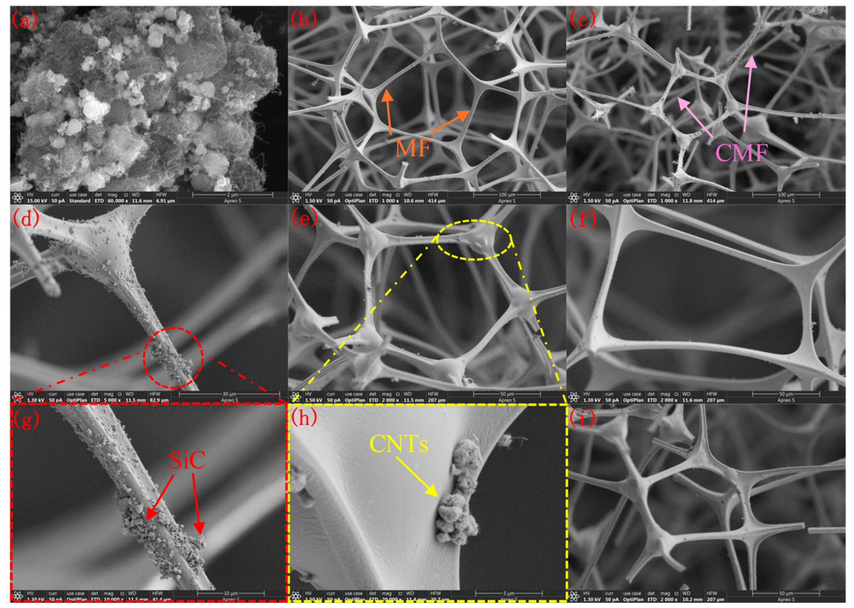
The microstructures of SiC–CNT hybrid filler, MF, and CMF were examined through scanning electron microscopy (SEM), as shown in Figure 1a–i. SiC particles are uniformly dispersed and form a “node–bridge” structure with CNTs, with no obvious agglomeration; CMF, after carbonization, develops a dense graphitized layer while preserving the internal porous structure, and its surface shows a uniform carbon layer with wrinkles and a high internal porosity, whereas non-carbonized MF has a smooth surface and low filler loading. For single-filler networks, SiC or CNTs tend to agglomerate noticeably; by contrast, the SiC–CNTs composite filler uniformly coats the CMF framework, with CNTs spanning the pores and tightly wrapping around SiC particles to form a continuous phonon transport pathway. This is attributed to mutual anchoring effects: SiC particles inhibit CNT agglomeration, and the CNT fibrous structure hinders SiC sedimentation.
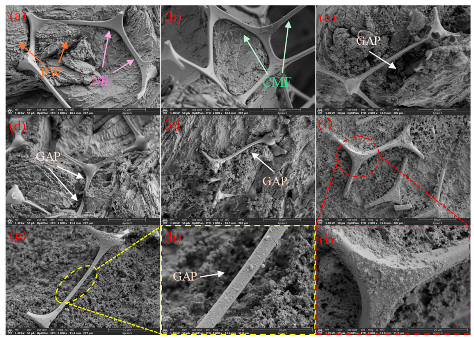
Figure 2 shows the micro-morphology of paraffin adsorption on different composites. MF/PW exhibits obvious gaps. After carbonization, CMF, owing to its surface carbon structure and wrinkles, has a noticeably better ability to adhere paraffin, and the network–paraffin gaps are significantly reduced; CMF@SiC/PW, CMF@CNTs/PW, and the physically mixed samples exhibit more pronounced voids and cracks in the network after paraffin adsorption due to filler agglomeration and sedimentation. In MF@SiC–CNTs/PW, the SiC–CNTs facilitate bridging between PW and MF, but the non-carbonized MF surface is smooth, giving a low adhesion capacity for SiC–CNTs powder and causing partial powder detachment that results in voids. In CMF@SiC–CNTs/PW, the SiC–CNTs hybrid network uniformly coats the CMF framework and is tightly connected to both the paraffin and the CMF framework, leading to a dense, complete structure after adsorption with no leakage.

2.2. Chemical Structure of the Composite Materials

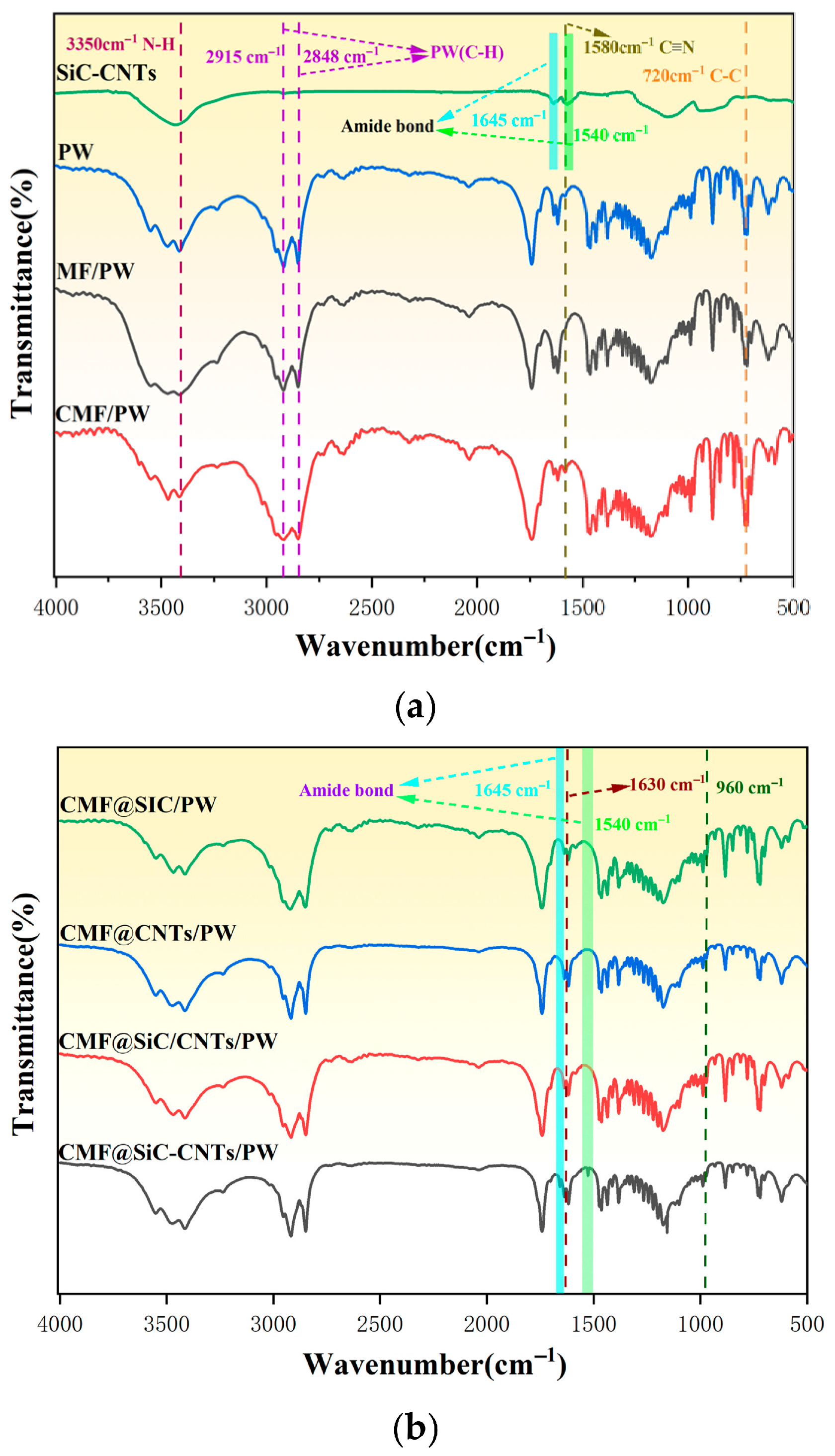
Figure 3 shows the FTIR features of the composite materials in the range of 500–4000 cm−1. The characteristic peaks of PW are concentrated at 2848 cm−1 and 2915 cm−1, corresponding to the symmetric and asymmetric stretching vibrations of C–H, and the weak peak at 720 cm−1 is attributed to the C–C backbone vibration. For carbonized CMF, the N–H stretching vibration (around 3350 cm−1) and the C≡N vibration (around 1580 cm−1) present in MF are significantly weakened, indicating partial carbonization of the melamine framework and the formation of graphitized structures. The CMF@SiC/PW sample shows a characteristic absorption peak of the Si-C bond at 960 cm−1, while CMF@CNTs/PW exhibits a new D peak at 1630 cm−1 (sp3hybridized carbon defects), indicating successful CNT loading. For the CMF@SiC–CNTs/PW composite system bonded via amide linkage, clear peaks at 1645 cm−1 and 1540 cm−1 corresponding to C=O (amide I) and N–H bending vibrations (amide II) appear, confirming chemical bonding interactions between SiC and CNTs. In contrast, the physically mixed CMF@SiC/CNTs/PW sample shows only a simple overlap of Si-C bond and CNT defect peaks, with no amide bond characteristic peaks observed, indicating no chemical interactions between the two components.

2.3. Crystal Structure Analysis

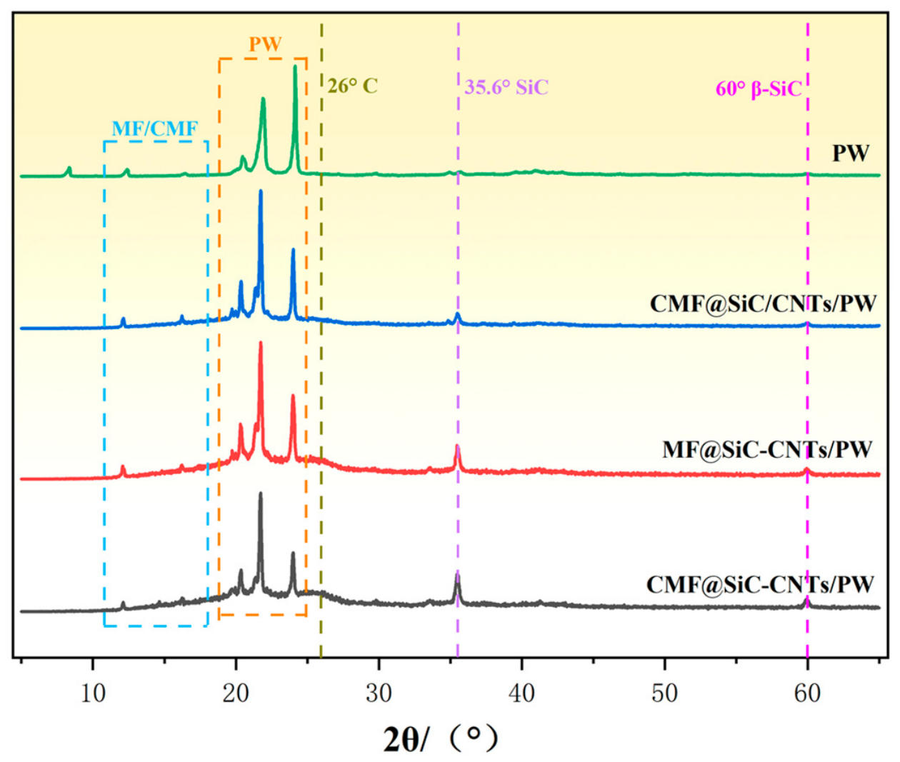
Figure 4 shows the XRD patterns, in the 20–60° diffraction angle range; all samples show the characteristic β-SiC diffraction peak at 35.6° and the carbon material (002) peak at 26°. The SiC(111) peak in the chemically bonded samples MF@SiC–CNTs/PW and CMF@SiC–CNTs/PW is significantly stronger than in the physically mixed sample CMF@SiC/CNTs/PW, confirming that amide-bond-mediated covalent linkage between SiC and CNTs effectively suppresses SiC agglomeration and enhances crystallographic order and dispersion uniformity. Meanwhile, the CMF support, after high-temperature carbonization, forms a highly conductive graphitized carbon framework, which markedly weakens the amorphous scattering background, leading to higher intensities of the SiC and carbon (002) peaks in the CMF-based samples CMF@SiC–CNTs/PW than in the MF-based samples MF@SiC–CNTs/PW. In addition, in the physically mixed sample, broadening and weakening of the SiC(111) peak indicate increased lattice defects due to weak interfacial interactions; whereas the evolution of the low-angle paraffin wax peak (21°) and the residual amorphous MF envelope (12–18°) further reveal differences in the crystallization behavior of the organic components constrained by the carbon phase within the composites. Regarding the crystallization behavior of PW within the composites, the PW (110) diffraction peak at 21° exhibits systematic differences among samples. The CMF-based sample CMF@SiC–CNTs/PW displays a sharper and more intense PW peak compared to the MF-based sample MF@SiC–CNTs/PW, suggesting that the graphitized carbon framework of CMF provides a more favorable surface for ordered PW molecular packing. The physically mixed sample CMF@SiC/CNTs/PW shows the broadest and least intense PW peak, indicating the most disordered crystallization, attributed to filler agglomeration and weak interfacial interactions that disrupt the regular arrangement of PW alkane chains. The weak amorphous scattering envelope in the 12–18° region, present in MF-based samples, is substantially reduced in CMF-based samples, consistent with the partial conversion of the melamine framework into ordered graphitic carbon during carbonization.

2.4. Thermal Stability Analysis

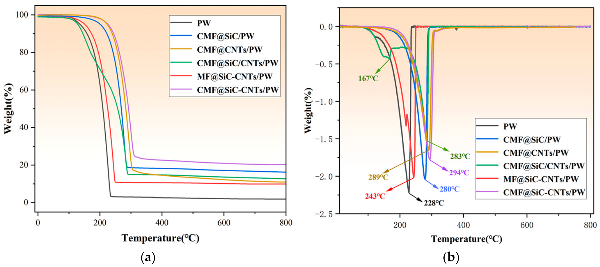
The TG and DTG curves of the samples are shown in Figure 5a,b. The thermal behavior can be divided into three characteristic regions: (i) From room temperature to 200 °C, the reversible solid–liquid phase transition of PW at 28–29 °C and the evaporation of trace free water within the CMF/MF pores at 80–120 °C occur; SiC, CNTs, and the covalent SiC–CNTs network show no thermal response. Structurally, the CMF-based samples, especially CMF@SiC–CNTs/PW, retain the CMF three-dimensional porous framework under capillary constraint and the anchoring effect of the SiC–CNTs network, so PW leakage is prevented and the skeleton remains dense and coherent; MF@SiC–CNTs/PW shows slight PW flow, while the physically mixed CMF@SiC/CNTs/PW exhibits filler agglomeration but no fracture. (ii) From 200 to 400 °C, PW decomposes vigorously around 228–280 °C with substantial mass loss. The PW decomposition start temperature in CMF@SiC–CNTs/PW is the highest at 294 °C, 66 °C higher than that of pure PW. MF decomposes at 360–400 °C due to rupture of triazine rings and methylene bridges, while CMF shows only limited detachment of carbon-chain-modified groups and the framework largely remains intact; the SiC–CNTs network loses only some physically adsorbed sites. CMF@SiC–CNTs/PW continues to maintain a three-dimensional framework; the single-filler systems exhibit some filler agglomeration but no framework damage; MF@SiC–CNTs/PW collapses because MF breaks down, and the physically mixed system shows localized pore deformation. (iii) From 400 to 800 °C, PW is completely degraded; MF is completely decomposed leaving only trace amorphous carbon; CMF undergoes further graphitization with minor mass loss; SiC and CNTs remain stable. Structurally, CMF@SiC–CNTs/PW retains an intact “CMF carbon framework + SiC–CNTs hybrid network”; CMF@SiC/PW and CMF@CNTs/PW show local particle accumulation due to lack of crosslinking between fillers; MF@SiC–CNTs/PW collapses completely; CMF@SiC/CNTs/PW becomes loose with CMF contraction and misalignment. The physically mixed CMF@SiC/CNTs/PW becomes loose, owing to framework contraction and poor interfacial adhesion between the unbonded fillers and the carbon matrix. Overall, within 800 °C, CMF@SiC–CNTs/PW exhibits the best structural stability across all regions.
The above structural evolution mechanisms were confirmed by the following evidence: (1) The stepwise mass losses in TG curves correspond well with the characteristic decomposition temperatures of individual components (PW decomposition at approximately 228 to 280 °C, MF decomposition at approximately 360 to 400 °C), confirming the assignment of each degradation stage. (2) DTG peak positions further distinguish the maximum-rate temperatures for each decomposition event, allowing clear separation of contributions from PW, MF, and CMF. (3) The residual mass above 600 °C shows distinct differences among samples: The CMF-based samples retain substantially higher residual mass than MF-based samples, consistent with the stability of the graphitized carbon framework and SiC–CNTs network, whereas MF@SiC–CNTs/PW leaves only trace residue due to complete MF decomposition and structural collapse. (4) Visual inspection of samples after TG analysis confirmed that CMF@SiC–CNTs/PW maintained its original monolithic shape, while MF@SiC–CNTs/PW disintegrated into powder, directly corroborating the stated structural stability differences.

2.5. DSC Tests and Cycling Stability Analysis

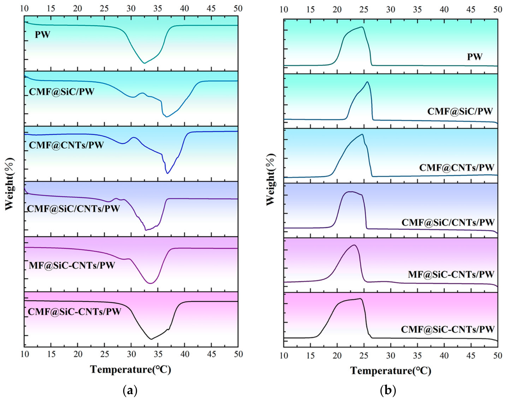
Differential scanning calorimetry (DSC) was employed to measure the heat flow difference between the sample and a reference as a function of temperature. The melting temperature (Tm) and crystallization temperature (Tc) were determined as the extrapolated onset temperatures of the endothermic and exothermic peaks, respectively. The melting enthalpy (ΔHm) and crystallization enthalpy (ΔHc) were calculated from the integrated areas of the corresponding DSC peaks. The total phase change enthalpy (ΔHtotal) was taken as the sum of ΔHm and ΔHc. The energy storage density (Ed) was defined as the percentage ratio of ΔHtotal of the composite to that of pure PW. The results are shown in Figure 6, and the thermophysical parameters are summarized in Table 1.
Pure PW DSC curve shows symmetric and sharp phase change peaks. This feature arises because its linear alkane molecular chains can achieve highly ordered arrangements during phase change—melting corresponds to the transition from a solid lattice to a liquid disordered state; due to the intrinsic undercooling of organic materials, Tc is slightly lower than Tm, and ΔHm and ΔHc are close. Energy reversibility is good, and Ed reaches 100%, highlighting the inherent latent heat storage potential.
Different composite systems exhibit significant hierarchical differences in peak sharpness and broadening due to variations in the carrier structure, filler–matrix interactions, and interfacial effects, and the heat storage performance follows suit:
For a single-filler system: In CMF@SiC/PW, SiC relies solely on phonon transfer for heat conduction and lacks a fibrous structure bridging CMF pores, causing local agglomeration. The agglomerates hinder the orderly arrangement of PW molecules, leading to substantial broadening of the DSC melting and crystallization peaks, reduced peak symmetry, and low Ed. In CMF@CNTs/PW, the fibrous CNTs structure can form partial linear heat conduction pathways inside CMF, improving heat transfer uniformity. Although slight agglomeration persists and CMF-CNTs are only physically adsorbed, the peak broadening is noticeably alleviated, and Ed is higher than in CMF@SiC/PW.
In CMF@SiC/CNTs/PW, SiC and CNTs are only mechanically mixed; interfacial gaps cause significant interfacial thermal resistance, and particle–fiber synergistic agglomeration can occur, severely disrupting the PW crystallization environment and greatly increasing molecular disorder. Its DSC peak broadening is the most pronounced, with reduced peak height, and its storage performance is the lowest among all systems.
MF@SiC–CNTs/PW: Although covalent bonding between SiC and CNTs via amide bonds suppresses agglomeration, the unmelted MF backbone lacks a graphitized layer; surface adsorption is weak and the intrinsic thermal conductivity is low, unable to help form a continuous heat conduction network. This leads to nonuniform heat distribution during PW phase change and restricted molecular crystallinity; DSC peak broadening is moderate. Ed, while better than physical mixing and single-SiC systems, remains inferior to CMF-based samples.
CMF@SiC–CNTs/PW: Via amide bonding, SiC–CNTs form covalent connections to create a continuous heat conduction network—“SiC nodes–CNT bridges”. SiC acts as a high-thermal conductivity phonon scattering center, and CNTs bridge the nodes to reduce interfacial thermal resistance. Meanwhile, the graphitized layer formed by carbonizing CMF provides high thermal conductivity and strong hydrophobicity; its three-dimensional porous structure affords strong capillary confinement of PW. The dual effects yield highly ordered PW molecular arrangements. Its DSC melting and crystallization peaks broaden only slightly, with intact and symmetric peak shapes and a temperature shift of less than 2.5 °C; Ed is the best among all systems, achieving synergistic optimization of storage and thermal conductivity.
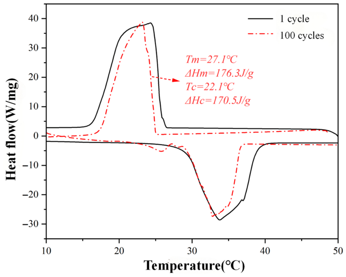
To further assess its long-term performance, CMF@SiC–CNTs/PW was subjected to 100 heating–cooling cycles. After cycling, the DSC curves in Figure 7 show that the melting enthalpy (ΔHm) is attenuated by less than 5%, and the melting temperature Tm changed insignificantly, indicating excellent cyclic thermal stability.

2.6. Temperature Regulation and Thermal Conductivity Analysis

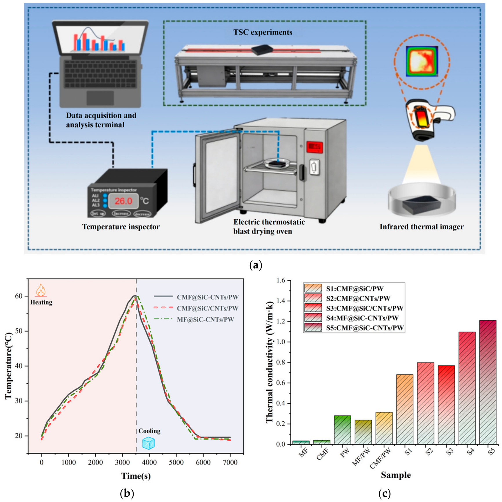
As shown in Figure 8a–c, to further study the composites’ latent heat and thermal conductivity and their impact on temperature regulation ability, thermal conductivity of each material was measured using a high-resolution thermal diffusivity scanner, and the temperature values during heating and cooling were recorded for CMF@SiCNTs/PW, MF@SiC–CNTs/PW, and CMF@SiC–CNTs/PW on a self-built platform. The platform employed a DC power supply (rated power: 30 W) with a constant heating rate of 2 °C/min and natural cooling at an average rate of approximately 1.5 °C/min. By examining the temperature variation curves during heating, all samples exhibited an isothermal plateau around 2300 s, indicating that the PCM is absorbing and releasing heat via latent heat. The relatively long duration is attributed to the large sample size (5 × 5 × 2 cm3), which results in a high thermal mass, combined with the moderate heating rate of the custom-built platform designed to ensure uniform temperature distribution throughout the sample volume. Among them, CMF@SiC–CNTs/PW showed noticeably higher heating and cooling rates, which is closely related to its high thermal conductivity. From the observed thermal conductivity results, MF/PW has a conductivity of only 0.2382 W/m·K, but both introducing thermal conductivity enhancers and carbonizing melamine foam can increase the thermal conductivity of phase change composites.
Overall, CMF@SiC–CNTs/PW shows the best thermal conductivity, 1.2117 W/m·K, which is 4.3 times that of pure PW (0.2813 W/m·K). For comparison, this represents an enhancement by a factor of approximately 5.1 relative to the non-carbonized MF/PW baseline (0.2382 W/m·K), highlighting the combined effect of carbonization and the SiC–CNTs hybrid network.
As shown in Table 2, the CMF@SiC–CNTs/PW composite achieves a favorable balance between thermal conductivity enhancement and latent heat retention compared with representative carbon-scaffold-based PCM composites. The thermal conductivity (1.21 W/m·K) and latent heat retention (79.0%) are both higher than those of the h-BN scaffold, carbonized MF/graphene, and carbonized MF/MoS2–rGO systems, confirming that the covalent SiC–CNTs network and graphitized CMF framework effectively mitigate the trade-off between conductivity enhancement and energy storage capacity.

3. Experimental Section

3.1. Materials

Melamine foam (MF, 9 kg/m3) was purchased from BASF, Ludwigshafen, Germany. Nano silicon carbide (SiC), multi-walled carbon nanotubes (CNTs), EDC, NHS were purchased from Shanghai Macklin Biochemical Co., Ltd., Shanghai, China. Concentrated sulfuric acid (H2SO4, 98%), concentrated nitric acid (HNO3, 65%), silane coupling agent (KH550), paraffin, and ethanol were purchased from Qingdao Jingke Chemical Reagent Co., Ltd., Qingdao, China. All reagents and solvents were analytical grade and used without further purification.

3.2. Sample Naming Rules

To clearly distinguish the sample components, a unified naming convention is established:
CMF: carbonized melamine foam (MF that has been carbonized);
CMF@SiC: CMF loaded with SiC (single-component filler);
CMF@CNTs: CMF loaded with CNTs (single-component filler);
MF@SiC–CNTs: non-carbonized MF loaded with SiC–CNTs hybrid filler;
CMF@SiC–CNTs: CMF loaded with SiC–CNTs hybrid filler.
After impregnation of the scaffold with PW (paraffin), “/PW” is appended (e.g., CMF@SiC–CNTs/PW);
Physical mixing control group: CMF@SiC/CNTs/PW (SiC and CNTs are not covalently bonded, simply physically mixed).

3.3. Preparation of SiC–CNTs Composite Powder

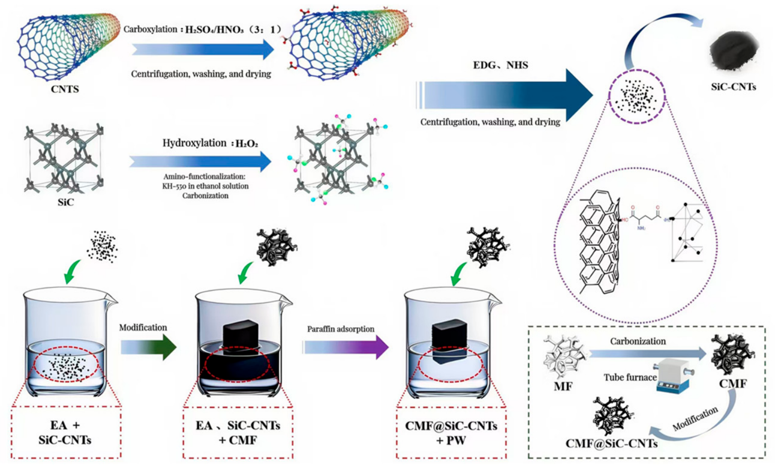
CNTs were placed in a mixture of H2SO4/HNO3 (volume ratio 3:1) and stirred at 60 °C for 6 h, centrifuged, washed, and dried. SiC was dispersed in H2O2 and stirred at 80 °C for 4 h, washed and dried, then immersed in KH550 ethanol solution, ultrasonicated for 1 h, and dried at 60 °C.
The oxidized CNTs and amino-functionalized SiC were reacted in an ethanol/water solution containing EDC/NHS as coupling agents. The pH was adjusted to 6.0, and the mixture was stirred at room temperature for 4 h, centrifuged and washed, and then anneal at 600 °C for 2 h under nitrogen to obtain the SiC–CNTs composite powder.

3.4. Carbonization of Melamine Foam

MF was cut into 5 × 5 × 2 cm3 blocks and placed in a tubular furnace under nitrogen (N2). The temperature was increased at 5 °C/min to 400 °C and held for 30 min to induce carbonization, which partially converted the melamine framework into a graphitized carbon structure. The degree of carbonization was verified by the significant weakening of N–H (~3350 cm−1) and C≡N (~1580 cm−1) vibrations in the FTIR spectra and the appearance of the (002) diffraction peak of graphitic carbon in XRD patterns (Section 3.2 and Section 3.3). After carbonization, the furnace was allowed to cool naturally to room temperature under nitrogen flow, and the sample was removed to obtain CMF.

3.5. Preparation of CMF@SiC–CNTs/PW Composite PCM and Control Groups

The SiC–CNTs hybrid filler was dispersed in ethanol to prepare a 5 wt% dispersion and ultrasonicate at 300 W for 30 min. CMF was immersed into the dispersion under −0.1 MPa vacuum for 30 min, removed, vacuum-dried at 60 °C for 12 h, and lightly tapped with a lint-free cloth to remove surface loose powder to obtain the CMF@SiC–CNTs scaffold.
PW was melted in an 80 °C constant-temperature water bath; the CMF@SiC–CNTs scaffold was immersed into the molten PW, and vacuum impregnation was performed at −0.1 MPa for 1 h, followed by 0.5 MPa pressurized impregnation for 20 min. This vacuum pressure cycle was repeated three times. The sample was removed, wrapped with filter paper, and heated at 80 °C for 30 s to remove surface PW, yielding the CMF@SiC–CNTs/PW composite PCM.
The control samples of CMF@SiC/PW, CMF@CNTs/PW, MF@SiC–CNTs/PW, and CMF@SiC/CNTs/PW were prepared through the same process, with differences only in filler type, carrier type, or bonding method; all other preparation parameters remain the same for subsequent performance comparison and analysis. The complete experimental procedure for preparing the CMF@SiC–CNTs/PW composite phase change material in this study is shown in Figure 9.

4. Conclusions

This study presents a synergistic strategy for addressing the long-standing trade-off between thermal conductivity enhancement and latent heat retention in paraffin-based phase change materials. The scientific novelty lies in the integration of three design elements: (i) a carbonized melamine foam (CMF) scaffold that provides a graphitized, thermally conductive three-dimensional framework with strong capillary confinement; (ii) covalent bonding between SiC and CNTs via amidation to construct a continuous “SiC node–CNT bridge” hybrid thermal conduction network that suppresses filler agglomeration and reduces interfacial thermal resistance; and (iii) a vacuum pressure cycling impregnation process that ensures dense and uniform loading of paraffin wax.
The resulting CMF@SiC–CNTs/PW composite achieves a thermal conductivity of 1.2117 W/m·K, representing a 4.3–fold enhancement over pure paraffin wax (0.2813 W/m·K), while maintaining a high latent heat retention of 79% (ΔHm = 185.6 J/g). After 100 heating–cooling cycles, the phase change enthalpy attenuates by less than 5%, demonstrating excellent cyclic stability. Thermogravimetric analysis confirms that the structural integrity is preserved up to 800 °C, outperforming single-filler, physically mixed, and non-carbonized carrier systems across all temperature regions.
A systematic comparison among control samples reveals the distinct roles of each structural component: the covalent SiC–CNTs network provides continuous phonon transport pathways, the graphitized CMF framework enhances both thermal conduction and structural robustness, and their combination yields a synergistic effect that cannot be achieved by either component alone or by simple physical mixing. This work establishes a design principle—namely, the coupling of a chemically bonded hybrid filler network with a carbonized porous support—that can be extended to the development of high-performance composite PCMs for thermal management applications.

Author Contributions

Conceptualization and funding acquisition: S.X.; writing—original: Y.L.; formal analysis: C.S.; writing—review and editing: X.L.; resource, data curation: H.J. and S.L. All authors have read and agreed to the published version of the manuscript.

Funding

This research received no external funding.

Data Availability Statement

The original contributions presented in this study are included in the article. Further inquiries can be directed to the corresponding author.

Conflicts of Interest

The authors declare no conflicts of interest.

References

  1. Zhang, H.; Liu, Z.; Mai, J.; Wang, N.; Zhong, J.; Mai, X.; Zhang, N. Super-elastic smart phase change material (SPCM) for thermal energy storage. Chem. Eng. J. 2021, 411, 128482. [Google Scholar] [CrossRef]
  2. Goel, V.; Saxena, A.; Kumar, M.; Thakur, A.; Sharma, A.; Bianco, V. Potential of phase change materials and their effective use in solar thermal applications: A critical review. Appl. Therm. Eng. 2023, 219, 119417. [Google Scholar] [CrossRef]
  3. Yuan, Y.; Zhang, Y.; Shi, S.; Wang, X.; Guo, H.; Zhou, W.; Wu, T.; Lu, H.; Ling, Z. Research progress on phase change heat storage exchangers for solar thermal utilization. Sol. Energy Mater. Sol. Cells 2026, 295, 113987. [Google Scholar] [CrossRef]
  4. Wang, Y.; Zhang, C.; Liu, Z.; Li, S. Sustainable self-healing asphalt mixture with microcapsules: Self-healing behavior and indicators analysis. J. Clean. Prod. 2026, 538, 147430. [Google Scholar] [CrossRef]
  5. Jamekhorshid, A.; Sadrameli, S.M.; Farid, M. A review of microencapsulation methods of phase change materials (PCMs) as a thermal energy storage (TES) medium. Renew. Sustain. Energy Rev. 2014, 31, 531–542. [Google Scholar] [CrossRef]
  6. Ma, Y.; Yang, H.; Zuo, H.; Zuo, Q.; He, X.; Chen, W.; Wei, R. EG@Bi-MOF derived porous carbon/lauric acid composite phase change materials for thermal management of batteries. Energy 2023, 272, 127180. [Google Scholar] [CrossRef]
  7. Xie, T.; He, Z.; Yu, H.; Ma, Y.; Shi, C.; Zhang, C.; Ge, J.; Dai, W. Evaluation of styrene butadiene rubber asphalt modification mechanism and adhesion effect based on molecular simulation. Fuel 2024, 364, 131023. [Google Scholar] [CrossRef]
  8. Cabeza, L.F.; Castell, A.; Barreneche, C.D.; De Gracia, A.; Fernández, A.I. Materials used as PCM in thermal energy storage in buildings: A review. Renew. Sustain. Energy Rev. 2011, 15, 1675–1695. [Google Scholar] [CrossRef]
  9. Tang, Z.; Gao, H.; Chen, X.; Zhang, Y.; Li, A.; Wang, G. Advanced multifunctional composite phase change materials based on photo-responsive materials. Nano Energy 2021, 80, 105454. [Google Scholar] [CrossRef]
  10. Kenisarin, M.; Mahkamov, K. Solar energy storage using phase change materials. Renew. Sustain. Energy Rev. 2007, 11, 1913–1965. [Google Scholar] [CrossRef]
  11. Li, S.Y.; Yan, T.; Huo, Y.J.; Pan, W.G. Carbon nanotube/carbon foam thermal-bridge enhancing solar energy conversion and storage of phase change materials. Mater. Today Sustain. 2024, 28, 100986. [Google Scholar] [CrossRef]
  12. Zhang, Z.; Alva, G.; Gu, M.; Fang, G. Experimental investigation on n–octadecane/polystyrene/expanded graphite composites as form–stable thermal energy storage materials. Energy 2018, 157, 625–632. [Google Scholar] [CrossRef]
  13. Qian, Z.; Shen, H.; Fang, X.; Fan, L.; Zhao, N.; Xu, J. Phase change materials of paraffin in h-BN porous scaffolds with enhanced thermal conductivity and form stability. Energy Build. 2018, 158, 1184–1188. [Google Scholar] [CrossRef]
  14. Mehrali, M.; Latibari, S.T.; Mehrali, M.; Metselaar, H.S.C.; Silakhori, M. Shape-stabilized phase change materials with high thermal conductivity based on paraffin/graphene oxide composite. Energy Convers. Manag. 2013, 67, 275–282. [Google Scholar] [CrossRef]
  15. Rigotti, D.; Dorigato, A.; Pegoretti, A. Effect of Paraffin Microcapsule and Carbon Nanotube Content on the Thermal Behavior of Thermoplastic Polyurethane Nanocomposites with Thermal Energy Storage Capability. J. Compos. Sci. 2026, 10, 10. [Google Scholar] [CrossRef]
  16. Inagaki, M.; Qiu, J.; Guo, Q. Carbon foam: Preparation and application. Carbon 2015, 87, 128–152. [Google Scholar] [CrossRef]
  17. Nardecchia, S.; Carriazo, D.; Ferrer, M.L.; Gutiérrez, M.C.; del Monte, F. Three dimensional macroporous architectures and aerogels built of carbon nanotubes and/or graphene: Synthesis and applications. Chem. Soc. Rev. 2013, 42, 794–830. [Google Scholar] [CrossRef] [PubMed]
  18. Zhiani, M.; Gholamian, M.; Barzi, S. Pd electrodeposition on a novel substrate of reduced graphene oxide/poly (melem-formaldehyde) nanocomposite as an active and stable catalyst for ethanol electrooxidation in alkaline media. Int. J. Hydrogen Energy 2022, 47, 3801–3813. [Google Scholar] [CrossRef]
  19. Zhang, Q.; Huang, J.Q.; Qian, W.Z.; Zhang, Y.Y.; Wei, F. The road for nanomaterials industry: A review of carbon nanotube production, post-treatment, and bulk applications for composites and energy storage. Small 2013, 9, 1237–1265. [Google Scholar] [CrossRef] [PubMed]
  20. Shamberger, P.J.; Bruno, N.M. Review of metallic phase change materials for high heat flux transient thermal management applications. Appl. Energy 2020, 258, 113955. [Google Scholar] [CrossRef]
  21. Alva, G.; Liu, L.; Huang, X.; Fang, G. Thermal energy storage materials and systems for solar energy applications. Renew. Sustain. Energy Rev. 2017, 68, 693–706. [Google Scholar] [CrossRef]
  22. Cui, W.; Li, X.; Li, X.; Si, T.; Lu, L.; Ma, T.; Wang, Q. Thermal performance of modified melamine foam/graphene/paraffin wax composite phase change materials for solar-thermal energy conversion and storage. J. Clean. Prod. 2022, 367, 133031. [Google Scholar] [CrossRef]
  23. Yu, Y.; Yang, P.; Yan, R.; Ren, F.; Yu, S.; Zhang, L.; Guo, J.; Li, R.; Xie, J. Tailoring pore and surface of carbonized melamine foam with graphene and RuO2 for efficient zinc-ion capacitor. J. Energy Storage 2024, 80, 110368. [Google Scholar] [CrossRef]
  24. Wang, Y.; Chen, Z.; Yang, L.; Xu, T.; Wu, H.; Zhang, J.; He, L. Effect of pre-heat treatment and carbonization temperature on comprehensive properties of melamine-derived carbon foam. Ceram. Int. 2024, 50, 31548–31558. [Google Scholar] [CrossRef]
  25. Yan, X.; Li, C.; Zhang, H.; Niu, Y. Construction of Co-doped Fe2O3/carbonized melamine foam heterogeneous catalyst for enhanced degradation of organic pollutants through peroxymonosulfate activation. Inorg. Chem. Commun. 2024, 161, 111984. [Google Scholar] [CrossRef]
  26. Feng, F.; Han, Z.; Li, Y.; Wang, F.; Liu, C.; Qu, Q.; Wei, B.; Wang, Q. High-performance SiC/CNT/RGO films through nanowelding engineering for electromagnetic shielding applications: Fabrication and optimization. FlatChem 2025, 53, 100909. [Google Scholar] [CrossRef]
  27. Balandin, A.A. Thermal properties of graphene and nanostructured carbon materials. Nat. Mater. 2011, 10, 569–581. [Google Scholar] [CrossRef] [PubMed]
  28. Shchegolkov, A.; Shchegolkov, A.; Demidova, A. The use of nanomodified heat storage materials for thermal stabilization in the engineering and aerospace industry as a solution for economy. MATEC Web Conf. 2018, 224, 03012. [Google Scholar] [CrossRef]
Figure 1. (a) SiC–CNTs, (b) MF, (c) CMF, (d,g) CMF@SiC/PW, (e,h) CMF@CNTs, (f) MF@SiC–CNTs, (i) CMF@SiC–CNTs composite material.
Inorganics 14 00206 g001
Figure 2. (a) MF/PW, (b) CMF/PW, (c) CMF@CNTs/PW, (d) CMF@SiC/PW, (e) MF@SiC–CNTs/PW, (f,i) CMF@SiC–CNTs/PW composite material morphologies, (g,h) CMF@SiC/CNTs/PW.
Inorganics 14 00206 g002
Figure 3. FTIR comparison of (a) SiC–CNTs, PW, MF/PW, and CMF/PW; and (b) CMF@SiC/PW, CMF@CNTs/PW, CMF@SiC/CNTs/PW, and CMF@SiC–CNTs/PW.
Inorganics 14 00206 g003
Figure 4. XRD patterns of the composite materials.
Inorganics 14 00206 g004
Figure 5. (a) TG curves of the composites and (b) DTG curves.
Inorganics 14 00206 g005
Figure 6. (a) DSC melting curves of different samples; (b) DSC solidification curves of different samples.
Inorganics 14 00206 g006
Figure 7. Cyclic thermal stability test curves.
Inorganics 14 00206 g007
Figure 8. (a) Schematic diagram of the custom experimental platform; (b) temperature rise and fall curves for the samples; (c) thermal conductivity test diagram.
Inorganics 14 00206 g008
Figure 9. Experimental flowchart.
Inorganics 14 00206 g009
Table 1. DSC test results for pure PW and various composites.
SampleTm (°C)ΔHm (J/g)Tc (°C)ΔHc (J/g)ΔHtotal (J/g)Ed (%)
Pure PW28.1231.8324.4228.9460.73100
CMF@SiC/PW28.8162.323.8156.7319.069.2
CMF@CNTs/PW29.1174.523.5168.2342.774.4
CMF@SiC/CNTs/PW29.3158.623.3153.4312.067.7
MF@SiC–CNTs/PW28.9169.823.9163.2333.072.3
CMF@SiC–CNTs/PW29.5185.623.2178.4364.079.0
Table 2. Comparison of thermal properties with previously reported PCM composites.
CompositeThermal Conductivity (W/m·K)Enhancement FactorLatent Heat (J/g)Energy Storage Density (%)Ref.
CMF@SiC–CNTs/PW1.214.3185.679.0this work
PW/h-BN porous scaffold0.853.4165.471.4[13]
Lauric acid–stearic acid/SiO2/EG0.923.7145.372.1[21]
PW/carbonized MF/graphene0.793.2171.874.2[22]
PEG/carbonized MF/MoS2–rGO0.662.6152.068.5[17]
Disclaimer/Publisher’s Note: The statements, opinions and data contained in all publications are solely those of the individual author(s) and contributor(s) and not of MDPI and/or the editor(s). MDPI and/or the editor(s) disclaim responsibility for any injury to people or property resulting from any ideas, methods, instructions or products referred to in the content.