
Article

Fabrication of High-Crystallinity ZnO Nanorods for Photocatalytic Application
School of Systems Engineering, Kochi University of Technology, Kami 782-8502, Kochi, Japan
*
Author to whom correspondence should be addressed.
Inorganics 2026, 14(6), 145; https://doi.org/10.3390/inorganics14060145
Submission received: 30 April 2026 / Revised: 21 May 2026 / Accepted: 23 May 2026 / Published: 27 May 2026
(This article belongs to the Special Issue New Advances into Nanostructured Oxides, 3rd Edition)

Abstract

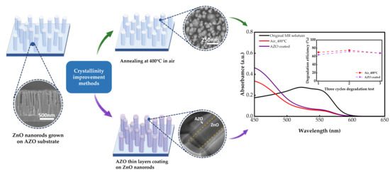
ZnO nanorods were synthesized on AZO substrates by chemical bath deposition, and were subsequently annealed under an air and vacuum ambient. Both annealing processes could improve the crystallinities of ZnO nanorods. The air-annealed ZnO nanorods showed higher crystallinity and partial reduction of oxygen-vacancy-related defects. The air-annealed ZnO nanorods exhibited a much higher photodegradation efficiency of 70% degradation for methyl red. In addition, as-grown ZnO nanorods were coated with undoped and Al-doped ZnO by mist chemical vapor deposition. Both coated thin layers modified the surface of ZnO nanorods, while the AZO-coated ZnO nanorods showed higher crystallinity and light absorption which resulted in the improvement in the photodegradation rate of methyl red. These findings demonstrate that appropriate annealing treatment and AZO surface engineering for ZnO nanorods are effective approaches for improving crystallinity, which leads to improvement of the photocatalytic efficiency of ZnO-based materials.

Graphical Abstract

1. Introduction

In the recent decades, the extensive use of organic dyes in various industrial processes has resulted in the generation of large amounts of wastewater. Among various organic dyes, azo dyes account for more than half of all industrial dyes [1]. These dyes can pose serious risks to human health and the ecological environment. For example, the aromatic amines produced by the cleavage of methyl red (MR) have been identified as having carcinogenic, mutagenic, hepatotoxic, and bladder toxicity risks [2]. Semiconductor photocatalysis, such as ZnO, CuO [3], TiO2 [4], WO3 [5] and Fe2O3 [6], have been demonstrated to be effective, sustainable, and versatile technology for degrading azo dyes [7,8,9]. Among them, ZnO is a lower-cost option than many others, making it more suitable for large-scale industrial production. ZnO is a promising semiconductor material because of its unique properties, including a wide direct bandgap of 3.37 eV, a large exciton binding energy of 60 meV, high optical transparency, high surface reactivity, and favorable electrical properties [10]. In addition to its intrinsic properties, ZnO is also an attractive material because of its low cost, wide availability, and versatile synthesis routes [11]. Among various fabrication methods for ZnO, including hydrothermal growth [12], sol–gel processing [13], vapor-phase deposition [14], and sputtering techniques [15], each method has both advantages and disadvantages. Vapor-phase and vacuum-based methods can provide high crystallinity and excellent structural control; however, they generally require expensive equipment, high temperatures, and complicated fabrication procedures. In contrast, chemical bath deposition (CBD) offers a simple, low-cost, and low-temperature process suitable for large-area and flexible substrates [16]. Although CBD-grown ZnO nanorods may exhibit relatively lower crystallinity, the method provides excellent scalability, easy morphology control, and compatibility with industrial applications.
In recent years, many studies have focused on improving the photocatalytic performance of ZnO [17,18,19]. Various modification strategies have been developed for ZnO-based materials, including annealing treatment [20], elemental doping [21], surface-area engineering [22], etc. Annealing treatment has been widely reported as an effective strategy to modify the structural properties and photocatalytic performance of ZnO materials. Appropriate thermal treatment can improve crystallinity [23] and adjust defect states [24]. These previous studies on defect modulation have mainly focused on annealing treatments conducted at relatively high temperatures, typically above 500 °C. However, excessive annealing temperatures may also cause undesirable effects, such as grain growth, reduced surface area, and the fusion of ZnO nanorods into larger particles [25], which may lead to reduced degradation efficiency. The effects of annealing-induced changes in crystallinity and defect states on the photocatalytic performance of ZnO materials had not been sufficiently discussed. Moreover, surface engineering has been recognized as an effective strategy to enhance the photocatalytic performance of ZnO materials [16]. Increasing the specific surface area can expose more catalytically active sites [26], enhance the adsorption of organic pollutants on the catalyst surface, and shorten the migration distance of photogenerated charge carriers to surface reaction sites [27], thereby improving photocatalytic degradation efficiency. Recently, several studies have attempted to modify the surface of ZnO materials through coating strategies [28], including coating different materials to form composite or shell-layer structures [29], as well as coating similar materials to achieve secondary growth [30,31]. However, most of these studies have mainly focused on ZnO powders or nanoparticles, which are less favorable for practical recycle and reuse. In contrast, surface modification of the recyclable nanorod-structured ZnO films has been comparatively less explored.
In our previous study, well-aligned ZnO nanorods could be fabricated on Al-doped ZnO (AZO) substrates, and the influence of deposition time on the photocatalytic performance of ZnO nanorods was investigated [32]. In addition, the mist chemical vapor deposition (mist CVD) method was used to deposit ZnO thin film and AZO film with precise thickness control on glass substrates. To further improve the photodegradation efficiency for azo dyes, in this study, thermal annealing in different ambient and surface coating methods was proposed to improve the crystallinity of ZnO nanorods. The photodegradation effects of MR dye using obtained ZnO nanorods were investigated.

2. Results and Discussion

2.1. Effect of Annealing Ambient

2.1.1. Structural Properties of ZnO Nanorods

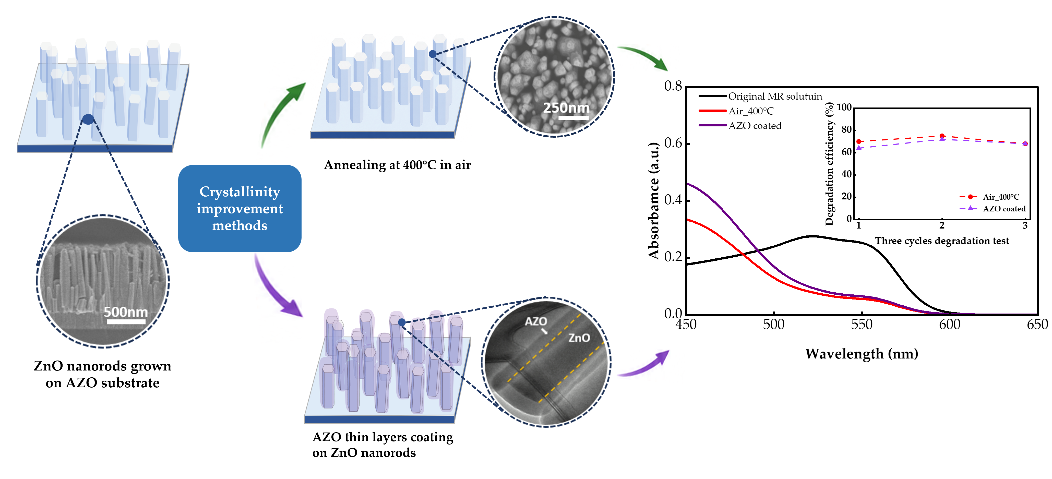
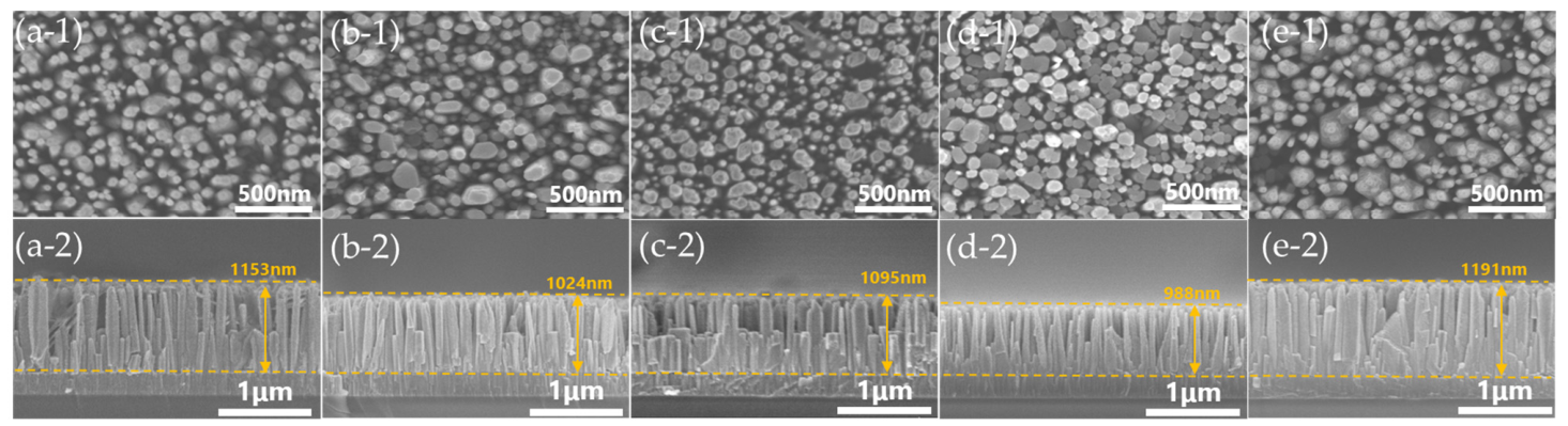
Figure 1 shows the scanning electron microscope (SEM) images of as-grown ZnO nanorods (NRs), annealed at 300 °C and 400 °C in a vacuum and air ambient respectively. Further statistical analysis of the nanorod diameter distribution was carried out with area (2.5 × 2.5 µm2) about 100 nanorods for each sample from top view of a SEM image. The length measurement was from a cross-section view of SEM images as shown in Figure 2b. It can be clearly observed that the ZnO nanorods formed vertically aligned arrays on the AZO substrates, with a length of 1153 nm and a diameter distribution mainly in the range of 50~60 nm after the CBD process. After annealing in the vacuum, the length of nanorods was slightly decreased to 1024 nm at 300 °C and 1095 nm at 400 °C, while the diameters distribution mainly increased to the ranges of 70~80 nm and 60~70 nm respectively. However, the morphology of nanorods was significantly changed after annealing in an air ambient. The length of nanorods was estimated to decrease to approximately 988 nm at 300 °C after air annealing with a diameter mostly distributing in the range of 60~70 nm. The length of ZnO nanorods was significantly increased to 1191 nm with the distribution diameter mostly in the range of 60~70 nm after annealing at 400 °C. In addition, the sheet resistance of the samples was measured to be 8.985 Ω/□ (as-grown), 8.158 Ω/□ (300 °C vacuum annealing), 8.177 Ω/□ (400 °C vacuum annealing), 15.85 Ω/□ (300 °C air annealing), and 26.85 Ω/□ (400 °C air annealing).
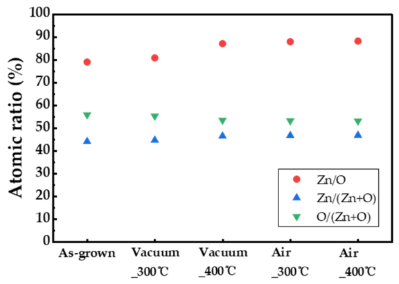
In order to study the effects of annealing ambient on elemental composition, energy-dispersive X-ray spectroscopy (EDX) analysis was conducted. The atomic ratios of Zn/O, Zn/(Zn + O) and O/(Zn + O) are shown in Figure 3. The as-grown ZnO nanorods exhibited Zn/O, Zn/(Zn + O), and O/(Zn + O) ratios of 79.03%, 44.14%, and 55.86%, respectively. After vacuum annealing at 300 °C and 400 °C, the Zn/(Zn + O) ratios increased to 44.71% and 46.55%, while the O/(Zn + O) ratios decreased to 55.29% and 53.45%, respectively. Therefore, the Zn/O ratio increased to 87.08% after vacuum annealing at 400 °C, indicating a Zn/O ratio increase resulting in the ZnO compound increasing more than those the 300 °C vacuum-annealed samples. During vacuum annealing, more oxygen atoms could escape from the ZnO lattice with a temperature increase, resulting in a Zn/O ratio increase toward stoichiometric ZnO. After air annealing, Zn/(Zn + O) and O/(Zn + O) showed a similar tendency to those observed after vacuum annealing. The 300 °C air-annealed sample exhibited Zn/(Zn + O), and O/(Zn + O) ratios of 46.78%, and 53.22%, respectively. At 400 °C, the Zn/(Zn + O) and O/(Zn + O) ratios slightly changed to 46.87%, and 53.13%, while the Zn/O ratio increased to 88.20% indicating an increase in stoichiometric ZnO, because the oxygen-containing ambient may promote further reaction and improve the crystallinity of ZnO during air annealing.
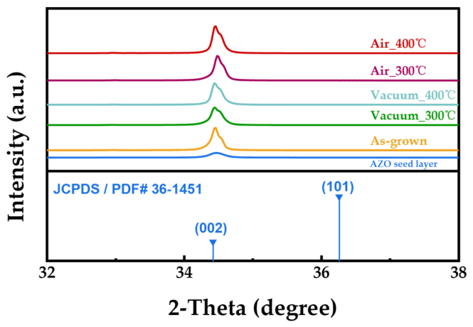
The XRD patterns revealed the effect of annealing on the crystal structure, as shown in Figure 4. The structural properties of the annealed ZnO nanorods are exhibited in Table 1. Only (002) diffraction peaks were obtained for these five samples. The intensity of the (002) peak increased almost in order of as-grown nanorods, vacuum-annealed nanorods, and air-annealed nanorods. In contrast, the FWHM values slightly decreased in the same order. A slight asymmetric broadening with a sligh shoulder observed close to the ZnO (002) peak in several samples might be due to the different crystallite sizes and higher compressive stress from the AZO seeds layer. The c-axis crystallite sizes were estimated using the Scherrer equation [33]; the calculated results were 46.8 nm for the as-grown nanorods, and 41.8 nm and 46.0 nm for the 300 °C and 400 °C vacuum-annealed nanorods respectively. The c-axis crystallite size was much higher for air-annealed nanorods, 48.5 nm and 48.2 nm for the 300 °C and the 400 °C air-annealed nanorods respectively. Based on Bragg’s law, the calculated lattice constants of all samples were nearly 5.2 Å, indicating there was negligible lattice distortion. These results indicate that the annealing process could improve the crystallinity of ZnO nanorods, and the improvement was more pronounced with air annealing compared to a vacuum ambient. Compared with 300 °C annealed ZnO nanorods, the 400 °C annealing process provided sufficient thermal energy to induce atomic rearrangement within the ZnO nanorods, resulting in crystallinity improvement after both vacuum and air annealing. In addition, annealing in air introduced an additional oxygen source which could promote regrowth of ZnO, leading to higher crystallinity.

2.1.2. Optical Properties of ZnO Nanorods

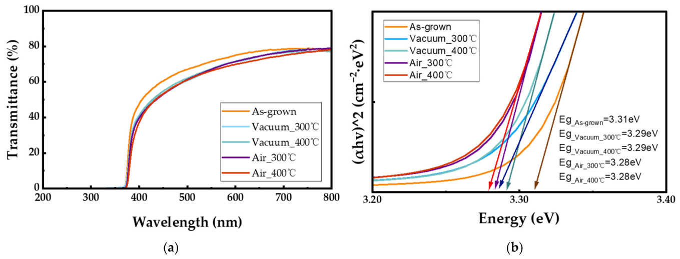
The transmittance spectra of the as-grown and annealed ZnO nanorods in different ambient are shown in Figure 5. After annealing in both the vacuum and air ambient, the ZnO nanorods showed decreased transmittance of about 61% compared with 67% for the as-grown ZnO nanorods. In order to investigate the bandgap energy change, Tauc plots were applied to estimate the optical bandgap as shown in Figure 5b. The bandgap was estimated using Equation (1) [34].
( α h v ) 1 / n = A h v E g
where α is the absorption coefficient, hv is the photon energy, A is a constant and Eg is the optical bandgap. The optical bandgap energies are estimated to be 3.32 eV for the as-grown sample, 3.29 eV for the vacuum-annealed sample, and 3.28 eV for the air-annealed sample. The negligible variation in bandgap energy suggests that annealing had a limited influence on the intrinsic electronic structure of ZnO.
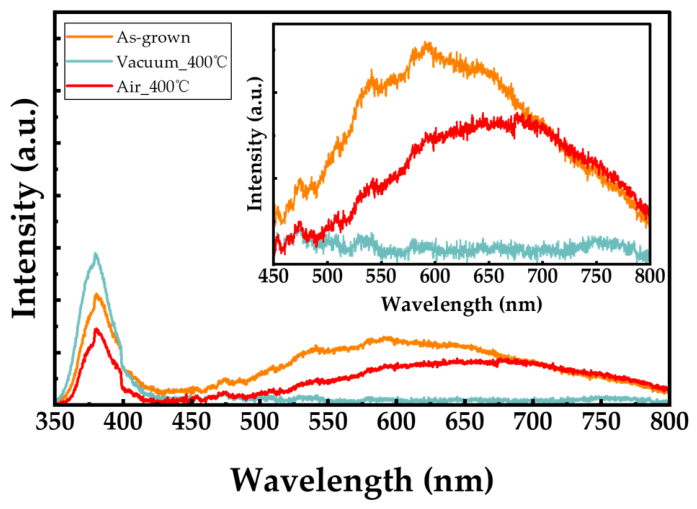
To further investigate the defect-related photoluminescence (PL) behavior of ZnO nanorods, PL measurements were performed on the as-grown, vacuum-annealed and air-annealed 400 °C samples, which exhibited relatively better crystallinity. The PL spectra are shown in Figure 6. All samples exhibited a near-band-edge (NBE) ultraviolet emission centered around 380 nm, which is generally associated with band edge emission. In addition, a broad visible emission peak from 580 nm to 660 nm was observed in both the as-grown sample and air-annealed sample, which were associated with oxygen interstitials or surface oxygen-related defects [35]. This red shift in the visible emission after air-annealing suggests the air annealing promoted stoichiometric ZnO reducing the oxygen interstitials. Compared with the as-grown sample, the vacuum-annealed sample exhibited an improved NBE emission together with a strongly suppressed visible emission band. This result suggests that vacuum annealing improved the crystallinity of ZnO nanorods and reduced defect-related recombination centers.

2.1.3. Photocatalytic Performance

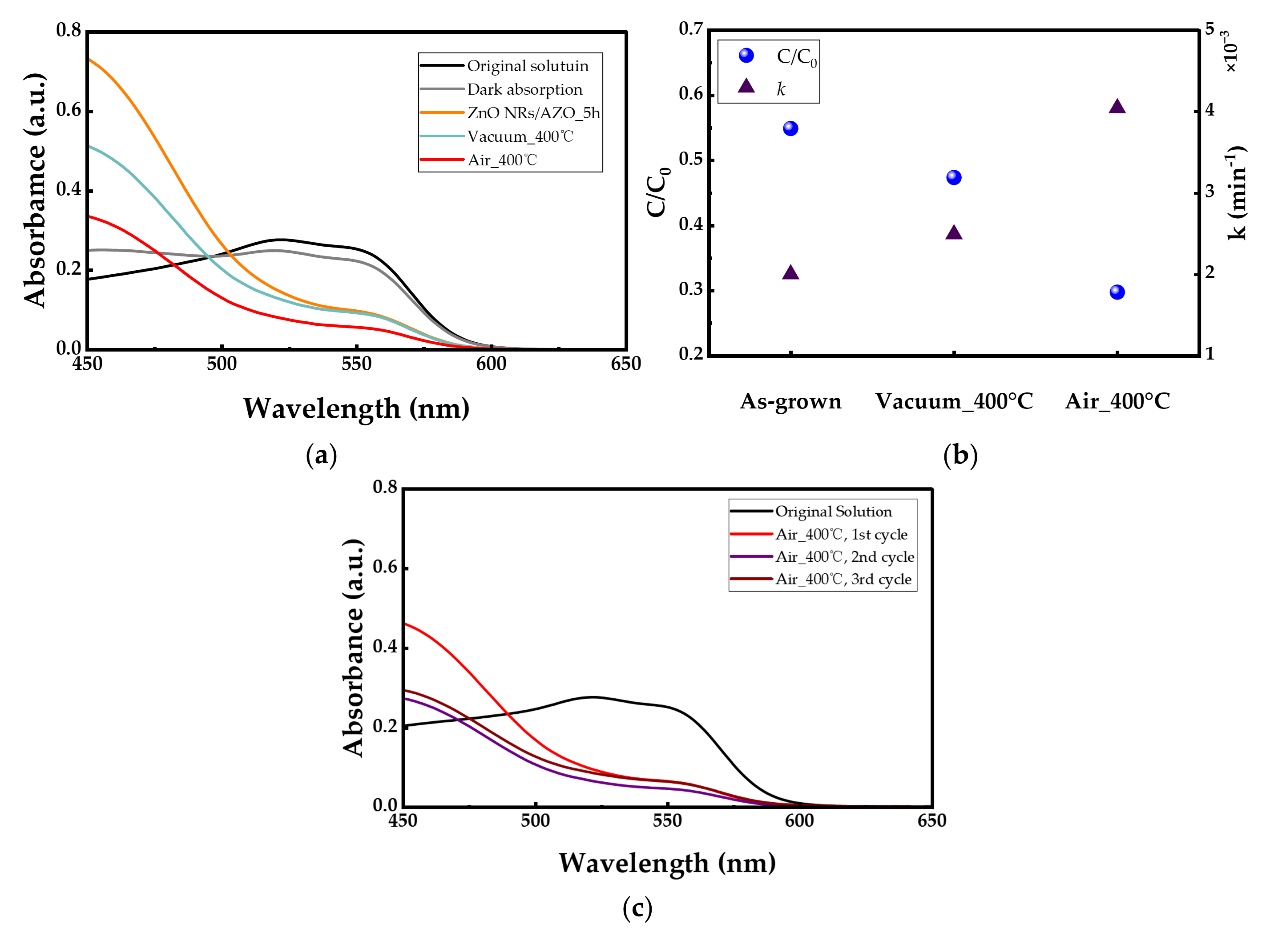
Since the samples annealed at 400 °C showed relatively better crystallinity, only the ZnO nanorods annealed at 400 °C in two different ambient conditions were selected for subsequent photocatalytic performance evaluation. Figure 7 shows the UV-vis absorption spectra of MR solution after photocatalytic degradation under UV irradiation, together with the corresponding normalized concentration (C/C0) and degradation efficiency over the as-grown and annealed ZnO nanorods. According to the Langmuir–Hinshelwood(L-H) model [36], the degradation rate of MR could be estimated by a pseudo-first-order reaction at low concentrations, as shown in Equation (2).
ln C 0 / C = k t
Prior to UV irradiation, a dark adsorption test was conducted to evaluate the adsorption behavior of the samples. After 30 min of dark adsorption, the MR concentration decreased by 9.8% for the air-annealed ZnO nanorods, indicating that adsorption contributed only slightly to the initial concentration decrease. After 5 h of UV irradiation, the air-annealed ZnO nanorods exhibited the highest photocatalytic activity, followed by the vacuum-annealed and as-grown ZnO nanorods. The highest degradation efficiency was 70% for the air-annealed ZnO nanorods with a degradation rate of 0.0041 min−1, followed by 53% for the vacuum-annealed ZnO nanorods with a degradation rate of 0.0025 min−1 and 45% for the as-grown sample with a rate of 0.0020 min−1. To further evaluate the reusability of the photocatalyst, the air-annealed ZnO nanorods with the highest photocatalytic activity were subjected to a total of three repeated degradation cycles, as shown in Figure 7c. The degradation efficiencies remained relatively stable at approximately 68~75% with values of 70%, 75% and 68% for the 1st, 2nd and 3rd cycles, respectively. These results indicate that the prepared samples exhibited a certain degree of reusability and potential practical applicability for photocatalytic degradation.
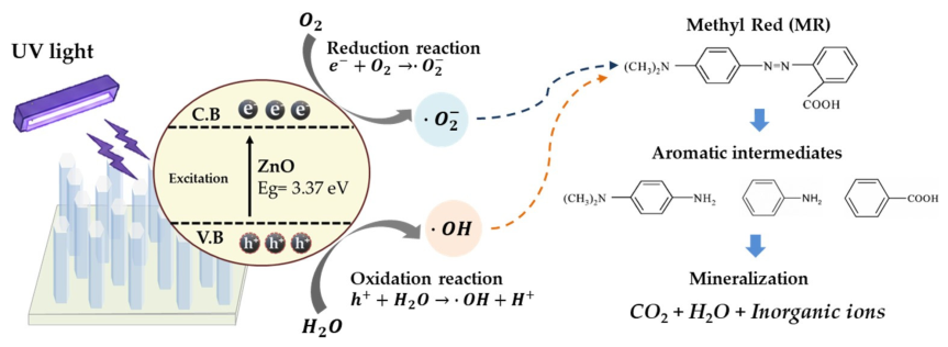
When UV light irradiated ZnO nanorods which were put into the MR solution, electrons in the valence band of ZnO were excited to the conduction band, leaving holes in the valence band and generating electron–hole pairs. These electrons and holes could migrate to the nanorod surface and react with adsorbed species, leading to the formation of reactive oxygen species such as hydroxyl radicals (·OH) and superoxide radicals (·O2) as shown in Figure 8. These reactive oxygen species played an important role in the degradation of MR dyes. Previous studies have also reported that superoxide radicals (·O2) play a dominant role in the photocatalytic degradation of azo dyes [37]. MR molecules are first attacked by ·OH and ·O2 radicals to form aromatic intermediates [38], which are subsequently oxidized into smaller species and finally degraded into CO2, H2O, and inorganic ions. Improved crystallinity is generally associated with reduced charge carrier recombination and enhanced charge transport, which can facilitate the photocatalytic process. In addition, the PL results suggest that the air-annealed ZnO nanorods retained oxygen-related surface defect states. These defects could act as carrier-trapping or surface-reaction sites, promoting charge separation and the generation of reactive oxygen species. Therefore, the superior photocatalytic performance of the air-annealed ZnO nanorods could be attributed to both effect of improved crystallinity and modified oxygen-related defect states.

2.2. Effect of Surface Coating of ZnO Nanorods

2.2.1. Structural Properties of ZnO Nanorods

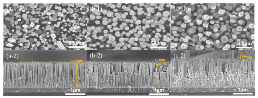
ZnO nanorods were synthesized on AZO substrates using the CBD method, which was followed by a mist CVD coating process. Figure 9 shows the SEM images of the as-grown ZnO nanorods and the nanorods coated with ZnO and AZO thin layers respectively for 10 min at 400 °C. It could be observed that the vertically grown ZnO nanorods exhibit a height of about 1560 nm with a diameter of 147 nm. After coating ZnO for 10 min, the diameter of nanorods were 162 nm, but became much more uniform and the length of nanorods was slightly increased to 1691 nm. The ZnO nanorods exhibited improved diameter uniformity with a larger size of 176 nm, and the length was increased to 1714 nm after AZO coating for 10 min.
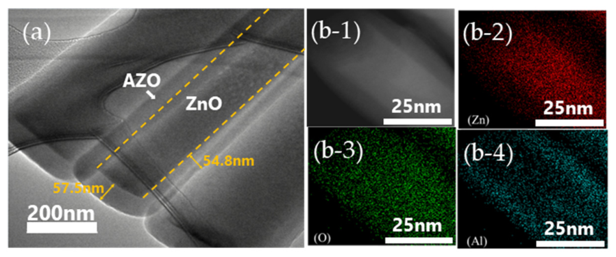
To further verify the formation of the AZO coating layer, Transmission Electron Microscopy (TEM) and EDX analysis were performed, as shown in Figure 10. As shown in Figure 10a, the nanorod exhibited a clear coating layer, where the ZnO nanorod as a core was surrounded by a lighter coating layer with a uniform layer of approximately 54.8 nm. In Figure 10(b-1–b-4), elemental mapping reveals the distribution of Zn, O and Al. It could be observed that Zn and O were uniformly distributed in the center area, while Al was uniformly distributed on the surface area of nanorod, as shown in Figure 10(b-4), indicating the successful formation of the AZO coating layer on a ZnO nanorod.
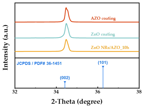
The XRD patterns of as-grown and coated ZnO nanorods are shown in Figure 11, and the structural properties of the ZnO nanorods obtained from XRD analysis are shown in Table 2. Only (002) peaks were obtained in the three samples, located at 34.49° for the as-grown sample and 34.50° for both ZnO-coated and AZO-coated samples, indicating a strong preferred orientation along the c-axis, same as ZnO nanorods, because the ZnO coating and AZO coating were the re-growth ZnO layers on ZnO nanorods which were the growth core. Compared to as-grown nanorods, both ZnO- and AZO-coated nanorods exhibited an increased (002) peak intensity. Although the AZO-coated sample exhibited the highest peak intensity and the narrowest FWHM of 0.181°, the FWHM among the three samples was not significantly changed, with values of 0.184° and 0.187° for as-grown and ZnO-coated samples, respectively. Therefore, the crystallite sizes were calculated using the Scherrer equation, which mainly reflects the coherent crystalline domain size along the c-axis. The calculated crystallite sizes are very similar, ranging from 44.4 to 46.0 nm: 45.3 nm for the as-grown sample, 44.4 nm for the ZnO-coated sample, and 46.0 nm for the AZO-coated sample. All calculated lattice constants c were close to the value of 5.20 Å. These results indicate that coated nanorods maintained high crystalline quality after the mist CVD coating process, with slight crystallinity improvements observed for AZO-coated samples.

2.2.2. Optical Properties of ZnO Nanorods

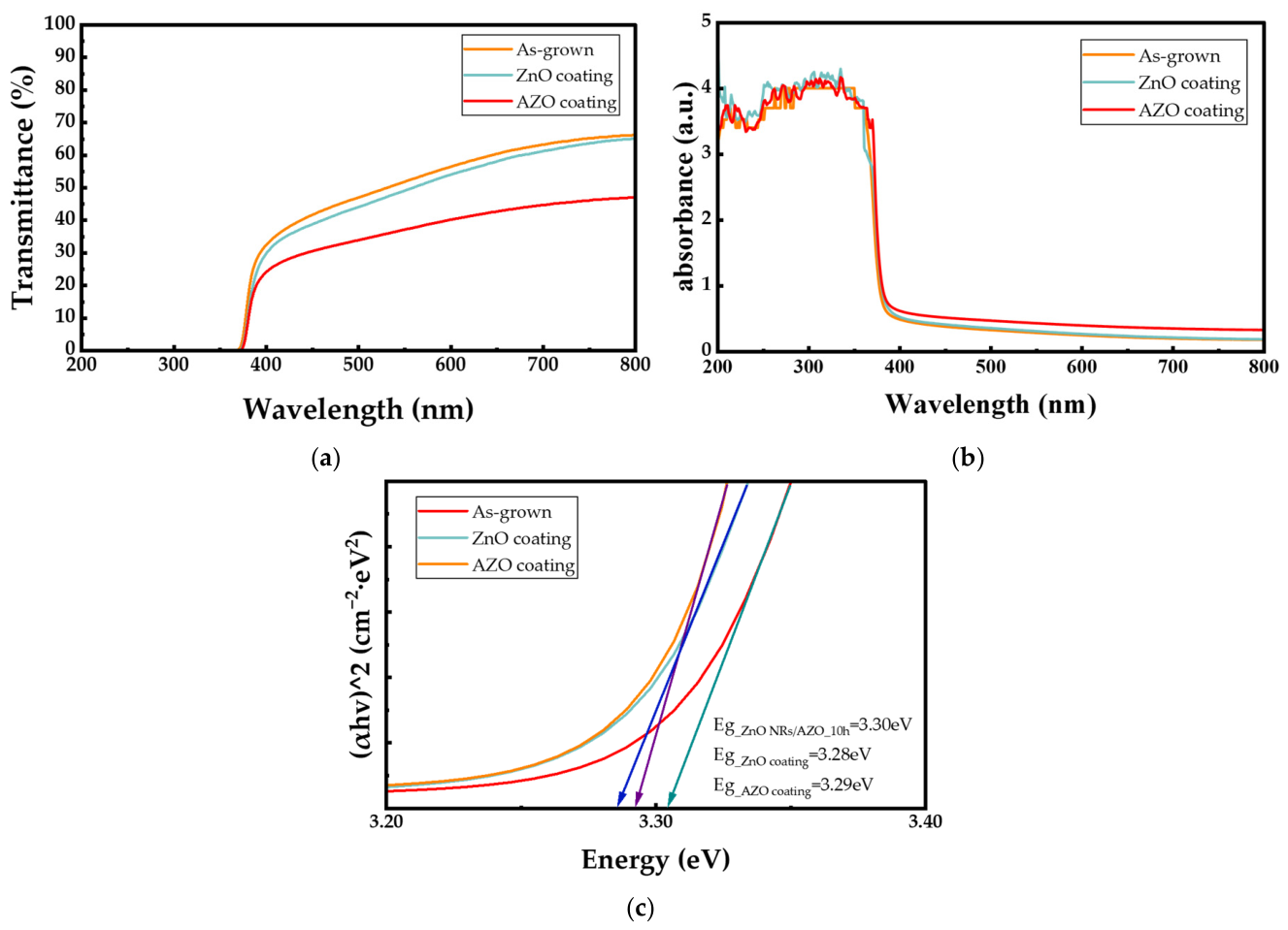
The transmittance and absorbance spectra of as-grown nanorods and ZnO-coated and AZO-coated nanorods are shown in Figure 12. The corresponding Tauc-plot images are displayed in Figure 12c. The as-grown nanorods exhibited a transmittance of 47.04% in the visible region. After ZnO coating, the transmittance slightly decreased to 44.1%, and further decreased to 33.94% after AZO coating. In contrast, the absorbance spectra showed an opposite tendency. The AZO-coated sample exhibited higher absorbance than the as-grown and ZnO-coated samples, especially in the visible region, indicating enhanced light utilization after AZO coating. However, the absorption edges of the three samples were similar, suggesting that the coating process had a limited influence on the intrinsic bandgap structure. The corresponding bandgap energies were calculated to be 3.30 eV for the as-grown sample, 3.28 eV for the ZnO-coated nanorods, and 3.29 eV for the AZO-coated nanorods.

2.2.3. Photocatalytic Performance

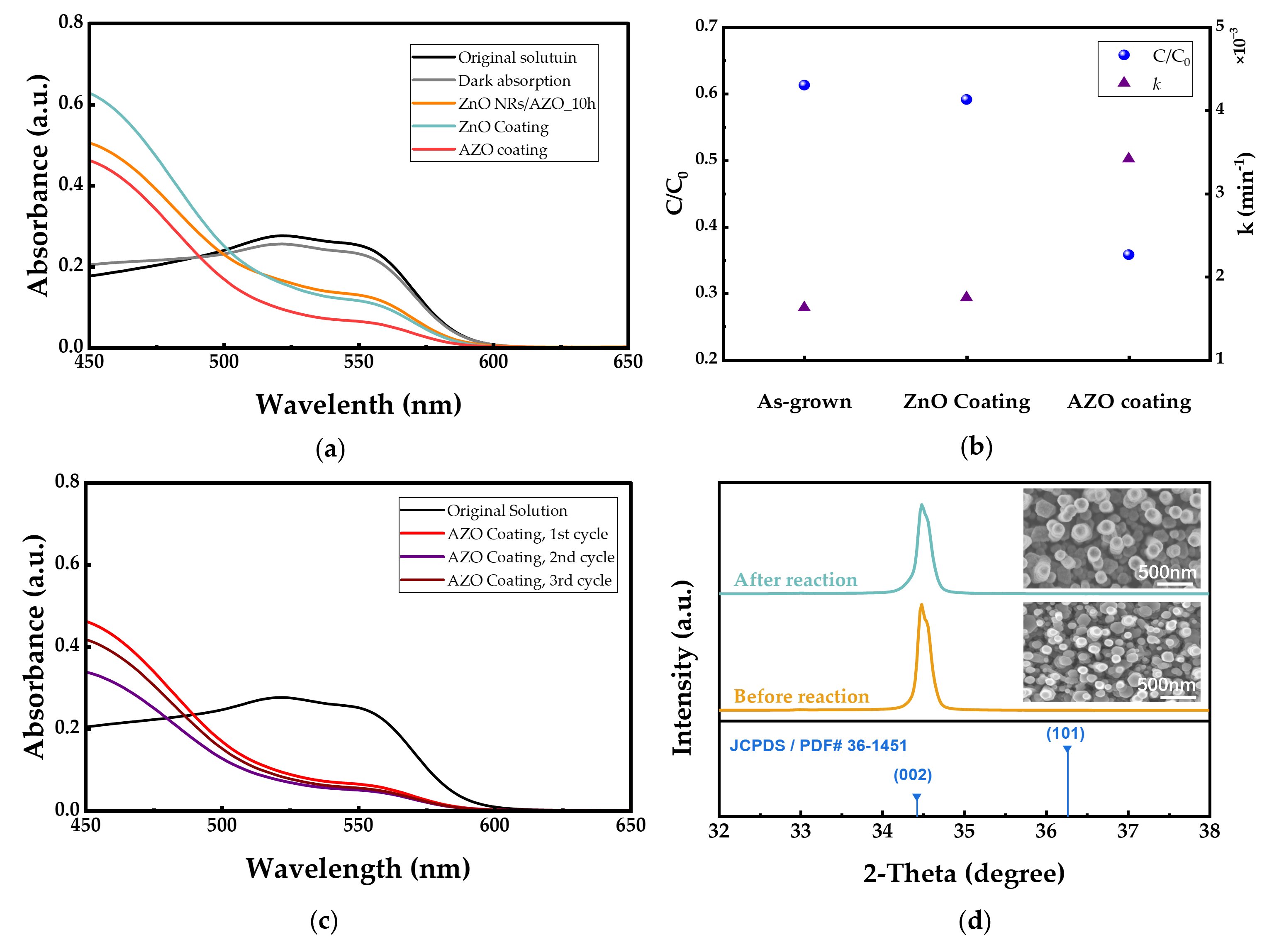
ZnO-coated and AZO-coated ZnO nanorods were used for photodegradation measurement. As-grown ZnO nanorods was also used as reference. The absorbance spectra of MR are shown in Figure 13. The MR absorption band at 520 nm was used to calculate the degradation rate of obtained ZnO nanorods. Prior to UV irradiation, the dark adsorption test showed that the MR concentration decreased by 7% for the AZO-coated sample, indicating a slight adsorption effect. All the samples showed significant absorbance intensity reduction at the MR characteristic wavelength of 520 nm. The as-grown ZnO nanorods showed the lowest photocatalytic efficiency of 39% with a photocatalytic degradation rate of 0.0016 min−1, followed by ZnO-coated nanorods which obtained a degradation efficiency of 41% with a rate of 0.0018 min−1. The AZO-coated sample exhibited the highest photocatalytic degradation efficiency of 64% and the degradation rate was calculated to be 0.0034 min−1. Furthermore, the reusability test results of the AZO-coated nanorods are shown in Figure 13c. The degradation efficiencies remained close at approximately 64~72%, with values of 64%, 72% and 68% for 1st, 2nd and 3rd cycles, respectively.
To further confirm the structural stability of the AZO-coated sample after repeated use, XRD and SEM characterizations were carried out. As shown in Figure 13d, the diffraction peak of the AZO-coated sample after reaction remained at 34.50°, which was consistent with that before the reaction. The FWHM after reaction was 0.192°, showing no significant change. Moreover, the SEM images showed that the ZnO nanorods were hardly morphologically changed after the reaction. These results indicate that the AZO-coated ZnO nanorods maintained good structural stability after repeated photocatalytic degradation.
Among these three samples, the AZO-coated sample exhibited the best photocatalytic performance. This improvement could be attributed to the combined effect of enhanced crystallinity and higher light absorption. The improved crystallinity may facilitate charge transport and ROS generation, while the higher absorbance of the AZO-coated nanorods could improve the utilization of incident light, thereby enhancing photocatalytic activity.

3. Materials and Methods

3.1. ZnO Nanorods Grown on AZO Substrates by CBD Method

ZnO nanorods were fabricated by chemical bath deposition (CBD) using a 300 nm-thick AZO substrate. A solution was prepared, combining zinc nitrate hexahydrate (Zn (NO3)2·6H2O, FUJIFILM Wako Pure Chemical Corporation, Osaka, Japan; 0.015 mol/L) with hexamethylenetetramine (HMTA, Tokyo Chemical Industry Co., Ltd., Tokyo, Japan; 0.0075 mol/L), which was dissolved in 200 mL of deionized water to form a precursor solution for the CBD process, as shown in Table 3. The AZO substrates were vertically immersed in reaction vessels containing the prepared growth solutions at 95 °C for 5 h and 10 h respectively, with the vessels covered with plastic film to minimize evaporation. Finally, the synthesized ZnO samples were rinsed with deionized water to eliminate the remaining salts, and dried with N2 gas.
Table 3. Experimental parameters for the CBD growth of ZnO nanorods.
SubstrateZn(NO3)2·6H2O (mmol)HMTA (mmol)Solvent (mL)Temperature (°C)Time (h)
AZO31.5200955, 10

3.2. Annealing Effects for ZnO Nanorods in Different Ambients

To investigate the influence of annealing conditions, the as-grown ZnO nanorods were annealed at 300 °C and 400 °C for 1 h under vacuum and air ambient respectively. Vacuum annealing was carried out in a quartz tube furnace, where the pressure was maintained at 2.4~4.8 × 10⁻³ Pa. Air annealing was performed in a rapid thermal annealing (RTA, MILA-3000, ULVAC-RIKO Inc., Yokohama, Japan) system.

3.3. ZnO Nanorods Coated AZO and ZnO Layers by Mist Chemical Vapor Deposition

AZO and ZnO layer coatings on as-grown nanorods were fabricated using mist chemical vapor deposition (Mist CVD). The deposition conditions are summarized in Table 4. For the ZnO coating, zinc acetate (ZA, Zn (CH3COO)2·2H2O, Sigma-Aldrich, St. Louis, MO, USA) was dissolved in a mixed solvent of deionized water and methanol (FUJIFILM Wako Pure Chemical Corporation, Osaka, Japan) at a volume ratio of 90:10 to obtain a total metal concentration of 0.04 mol/L. For the AZO coating, aluminum acetylacetonate (AA, Al (C5H7O2)3, Sigma-Aldrich, St. Louis, MO, USA) was additionally introduced into the zinc acetate precursor, corresponding to an Al content of 2 at.%. The mist droplets are generated from the precursor solution in the solution chamber using an ultrasonic transducer with a frequency of 2.4 MHz. The droplets are transported to the reaction chamber by N2 gas serving as a carrier gas (2.5 L·min−1) and a dilution gas (4.5 L·min−1). The substrates were placed in the reaction chamber maintained at 400 °C, and the coating time was 10 min.
Table 4. Deposition conditions for the mist CVD coating process.
Deposition ParametersConditions
SoluteZinc acetate, aluminum acetylacetonate
Solvent compositionMethanol and DI water (10:90, v/v)
Total metal concentration (mol·L−1)0.04
Al content (at.%)0, 2
Ultrasonic frequency (MHz)2.4
Carrier gas (L·min−1)N2, 2.5
Dilution gas (L·min−1)N2, 4.5
SubstrateZnO nanorods/AZO
Substrate temperature (°C)400
Deposition time (min)10

3.4. Photocatalytic Degradation Experiment

To evaluate the photocatalytic degradation performance of ZnO nanorods, azo dye methyl red (MR, Hayashi Pure Chemical Ind., Ltd., Osaka, Japan ) was used as a model pollutant. The initial concentration of MR solution was fixed at 1 × 10⁻⁴ mol·L−1 throughout all photocatalytic experiments to ensure consistent comparison among different samples. A solution was prepared by dissolving 13.5 mg of the dye in 500 mL of deionized water. The solution was magnetically stirred in the dark until complete dissolution. Prior to irradiation, the samples (1.5 × 1.5 cm) were immersed in 70 mL of MR solution and kept in the dark for 30 min to establish adsorption–desorption equilibrium. Subsequently, the sample and solution were irradiated under ultraviolet light (254 nm) for 5 h with magnetic stirring. After irradiation, the solution was stored in the dark prior to analysis. In addition, to evaluate the reusability of the photocatalysts, the degradation experiment was repeated for three cycles under the same conditions, with each cycle lasting 5 h under UV irradiation.

3.5. Characterizations

Morphological, structural and optical characterizations were carried out for all the samples. The morphology and elemental compositions of ZnO nanorods were studied using a field-emission scanning electron microscope (FE-SEM, SU-8020, Hitachi, Tokyo, Japan) equipped with energy-dispersive X-ray spectroscopy (EDX) and Transmission Electron Microscopy (TEM, Titan ETEM G2, FEI, Hillsboro, OR, USA). The structural properties of the prepared samples were examined by X-ray diffraction (XRD, SmartLab, Rigaku Corporation, Tokyo, Japan). The optical properties and photocatalytic degradation performance of the samples were evaluated using a UV-visible spectrophotometer (U-4100, Hitachi, Tokyo, Japan). The sheet resistance was measured using a four-point probe system (Loresta-GP MCP-T610, Mitsubishi Chemical Corporation, Tokyo, Japan). Photoluminescence (PL) spectra were measured at room temperature using a He-Cd laser (IK3201R-F, KIMMON KOHA Co., Ltd., Tokyo, Japan) with an excitation wavelength of 325 nm as the excitation source.

4. Conclusions

The crystallinity of ZnO nanorods was improved by both annealing-treatment processes and surface-coating processes. Compared with vacuum annealing, air annealing contributed to the improvement of crystallinity significantly due to the oxygen supply during the annealing process and the partial reduction of oxygen-vacancy-related defects. Air annealing at 400 °C resulted in the highest crystallinity of ZnO nanorods, resulting in a higher degradation efficiency of 70% and degradation rate of 0.0041 min−1 toward the MR solution.
Both ZnO- and AZO-coated ZnO nanorods contributed to enhance the degradation rate of the MR solution. The AZO-coated sample exhibited the highest photocatalytic activity, with a degradation efficiency of 64%, which was attributed to improved crystallinity, enhanced light absorption capability, and effective surface modification rather than significant bandgap variation.
These results demonstrate that appropriate annealing treatment and Al-doped ZnO surface engineering are effective strategies for enhancing the photocatalytic performance of ZnO nanorods. Notably, the obtained photocatalytic efficiency was considered promising under the low catalyst-loading nanostructured thin-film photocatalytic system employed in this study. The present study provides a practical route for the development of ZnO-based thin-film photocatalysts for wastewater treatment applications.

Author Contributions

Conceptualization, C.L. and T.G.; methodology, T.I.; formal analysis, T.G. and T.I.; investigation, T.I. and T.G.; resources, C.L.; data curation, T.G.; writing—original draft preparation, T.G.; writing—review and editing, C.L.; visualization, T.G.; supervision, C.L.; project administration, C.L.; funding acquisition, C.L. All authors have read and agreed to the published version of the manuscript.

Funding

This research received no external funding.

Institutional Review Board Statement

Not applicable.

Informed Consent Statement

Not applicable.

Data Availability Statement

The original contributions presented in this study are included in the article. Further inquiries can be directed to the corresponding author.

Acknowledgments

Alexandra Apostoluk (Institut des Nanotechnologies de Lyon, INL, Lyon INSA, France) provided valuable support and academic exchange during this study. Lucille Joly Pottuz (Matériaux Ingénierie et Science, MateIS, Lyon INSA, France) provided valuable assistance with the TEM and TEM-EDX measurements. The authors sincerely express their gratitude to all of them for their support and contributions.

Conflicts of Interest

The authors declare no conflicts of interest.

References

  1. Chibite, E.E.A.; de Mendonça, D.E.A.; de Godoy, M.A.F.; do Nascimento, A.; Dos Santos Oliveira, J.A.; de Melo, B.A.R.; Heck, M.C.; Polonio, J.C.; Almeida, I.V.; Vicentini, V.E.P. A green approach to azo dye C.I. Disperse Blue 291 treatment: Mitigating ecotoxicological effects through enzymatic and adsorptive strategies using endophytic fungi. World J. Microbiol. Biotechnol. 2026, 42, 99. [Google Scholar] [CrossRef]
  2. Halim, O.M.A.; Mustapha, N.H.; Mohd Fudzi, S.N.; Azhar, R.; Zanal, N.I.N.; Nazua, N.F.; Nordin, A.H.; Mohd Azami, M.S.; Mohd Ishak, M.A.; Wan Ismail, W.I.N.; et al. A review on modified ZnO for the effective degradation of methylene blue and rhodamine B. Results Surf. Interfaces 2025, 18, 100408. [Google Scholar] [CrossRef]
  3. Bouras, D.; Khezami, L.; Barille, R.; Merah, N.; Salhi, B.; El-Hiti, G.A.; Guesmi, A.; Fellah, M. Preparation Methods and Photcatalytic Performance of Kaolin-Based Ceramic Composites with Selected Metal Oxides (ZnO, CuO, MgO): A Comparative Review. Inorganics 2025, 13, 162. [Google Scholar] [CrossRef]
  4. Mao, T.; Zha, J.; Hu, Y.; Chen, Q.; Zhang, J.; Luo, X. Research Progress of TiO2 Modification and Photodegradation of Organic Pollutants. Inorganics 2024, 12, 178. [Google Scholar] [CrossRef]
  5. Yu, C.; Yang, K.; Shu, Q.; Yu, J.C.; Cao, F.; Li, X. Preparation of WO3/ZnO composite photocatalyst and its photocatalytic per-formance. Chin. J. Catal. 2011, 32, 555–565. [Google Scholar] [CrossRef]
  6. Wannakan, K.; Nonthing, S.; Panchakeaw, A.; Nanan, S. Ternary Fe2O3/g-C3N4/ZnO photocatalyst for complete sunlight driven degradation of tetracycline antibiotic. Diam. Relat. Mater. 2025, 155, 112316. [Google Scholar] [CrossRef]
  7. Acosta-Silva, Y.d.J.; Lugo-Arredondo, M.I.; Gallardo-Hernández, S.; Garcia-Trejo, J.F.; Matsumoto, Y.; Rivas, S.; Feregrino-Pérez, A.A.; Godínez, L.A.; Méndez-López, A. Comparison of Photocatalytic Activity: Impact of Hydrophilic Properties on TiO2 and ZrO2 Thin Films. Inorganics 2024, 12, 320. [Google Scholar] [CrossRef]
  8. Nagesh, S.D.; Satheesh, D.; Ravi, R.D.; Pachaiappan, R.; Manavalan, K.; Cornejo-Ponce, L.; Sethuramachandran, T. An effective photocatalytic decomposition of azo dyes by NiO/ZnO/g-C3N4 ternary nanocomposite under solar light excitation. Surf. Interfaces 2025, 56, 105578. [Google Scholar] [CrossRef]
  9. Kumar, R.A.S.; Mary, V.D.; Josephine, S.G.A. Design of solar-light-driven agglomerated cluster-like transition/rare-earth metal oxide-supported carbon-based nanomaterial for the degradation of azo dye. Chem. Phys. Impact 2024, 8, 100563. [Google Scholar] [CrossRef]
  10. Bappy, N.F.; Subramani, S. A comprehensive review on Mg-doped ZnO thin film and nanostructure: Properties and applictions. Mater. Sci. Eng. B 2025, 318, 118251. [Google Scholar] [CrossRef]
  11. Bhapkar, A.R.; Bhame, S. A review on ZnO and its modifications for photocatalytic degradation of prominent textile effluents: Synthesis, mechanisms, and future directions. J. Environ. Chem. Eng. 2024, 12, 112553. [Google Scholar] [CrossRef]
  12. Ahn, S.E.; Lee, J.S.; Kim, H.; Kim, S.; Kang, B.H.; Kim, K.H.; Kim, G.T. Photo response of Sol-Gel-Synthesized ZnO Nanorods. Appl. Phys. Lett. 2004, 84, 5022–5024. [Google Scholar] [CrossRef]
  13. Gao, R.; Ma, X.; Liu, L.; Gao, S.; Zhang, X.; Xu, Y.; Cheng, X.; Zhao, H.; Huo, L. In-Situ Deposition of POMA/ZnO Nanorods Array Film by Vapor Phase Polymerization for Detection of Trace Ammonia in Human Exhaled Breath at Room Temperature. Anal. Chim. Acta 2022, 1199, 339563. [Google Scholar] [CrossRef] [PubMed]
  14. Nandi, R.; Major, S.S. The Mechanism of Growth of ZnO Nanorods by Reactive Sputtering. Appl. Surf. Sci. 2017, 399, 305–312. [Google Scholar] [CrossRef]
  15. Ruvalcaba-Manzo, S.G.; Ramírez-Bon, R.; Ochoa-Landín, R.; Castillo, S.J. A Comprehensive Study of the Optical, Structural, and Morphological Properties of Chemically Deposited ZnO Thin Films. Inorganics 2025, 13, 331. [Google Scholar] [CrossRef]
  16. Lin, Y.; Hu, H.; Hu, Y.H. Role of ZnO morphology in its reduction and photocatalysis. Appl. Surf. Sci. 2020, 502, 144202. [Google Scholar] [CrossRef]
  17. Pruna, A.; Poliac, I.; Busquets-Mataix, D.; Ruotolo, A. Effect of Electrodeposition Conditions on Adsorption and Photocatalytic Properties of ZnO. Materials 2025, 18, 497. [Google Scholar] [CrossRef]
  18. Mohan, H.; Mohandoss, S.; Balasubramaniyan, N.; Loganathan, S. Non-Thermal Plasma-Assisted Synthesis of ZnO for Enhanced Photocatalytic Performance. Plasma 2025, 8, 25. [Google Scholar] [CrossRef]
  19. Yang, R.; Lu, G.; Liang, H.; Li, Z.; Liang, J.; Chen, Z. Enhancing the Photocatalytic Performance for Norfloxacin Degradation by Fabricating S-Scheme ZnO/BiOCl Heterojunction. Molecules 2024, 29, 4738. [Google Scholar] [CrossRef] [PubMed]
  20. Abdel-Galil, A.; Hussien, M.S.A.; Balboul, M.R. Optimal thickness and annealing temperature for enhancement of structural, optical, and photocatalytic properties of ZnO thin films. J. Aust. Ceram. Soc. 2022, 58, 1667–1683. [Google Scholar] [CrossRef]
  21. Zheng, A.L.T.; Abdullah, C.A.C.; Chung, E.L.T.; Andou, Y. Recent progress in visible light-doped ZnO photocatalyst for pollution control. Int. J. Environ. Sci. Technol. 2023, 20, 5753–5772. [Google Scholar] [CrossRef]
  22. Abdel-Fattah, E.M.; Alshehri, S.M.; Alotibi, S.; Alyami, M.; Abdelhameed, D. Hydrothermal Synthesis of ZnO Nanoflowers: Exploring the Relationship between Morphology, Defects, and Photocatalytic Activity. Crystals 2024, 14, 892. [Google Scholar] [CrossRef]
  23. Cui, L.; Zhang, H.-Y.; Wang, G.-G.; Yang, F.-X.; Kuang, X.-P.; Sun, R.; Han, J.-C. Effect of annealing temperature and annealing atmosphere on the structure and optical properties of ZnO thin films on sapphire (0001) substrates by magnetron sputtering. Appl. Surf. Sci. 2012, 258, 2479–2485. [Google Scholar] [CrossRef]
  24. Naeem, R.; Mehmood, M.; Ali, S.M.; Ramay, S.M.; Shar, M.A.; AlGarawi, M.S. Annealing induced defects in ZnO nanostructures. Appl. Phys. A 2019, 125, 528. [Google Scholar] [CrossRef]
  25. Yan, Z.; Ma, Y.; Wang, D.; Wang, J.; Gao, Z.; Wang, L.; Yu, P.; Song, T. Impact of annealing on morphology and ferromagnetism of ZnO nanorods. Appl. Phys. Lett. 2008, 92, 081911. [Google Scholar] [CrossRef]
  26. He, H.; Fu, C.; Wei, W.; Ma, J.; Guo, X.; Xiao, J. Apple-like zinc-oxide mesocrystals as robust and versatile photocatalysts for efficient degradation of eight different organic dyes. ACS Omega 2022, 7, 409–418. [Google Scholar] [CrossRef]
  27. Nandi, P.; Das, D. Photocatalytic degradation of Rhodamine-B dye by stable ZnO nanostructures with different calcination temperature induced defects. Appl. Surf. Sci. 2019, 465, 546–556. [Google Scholar] [CrossRef]
  28. Schuler, T.; Aegerter, M.A. Optical, electrical and structural properties of sol-gel ZnO: Al coatings. Thin Solid Film. 1999, 351, 125–131. [Google Scholar] [CrossRef]
  29. Zhu, Y.F.; Fan, D.H.; Shen, W.Z. A general chemical conversion route to synthesize various ZnO-based core/shell structures. J. Phys. Chem. C 2008, 112, 10402–10406. [Google Scholar] [CrossRef]
  30. Wu, Y.L.; Tok, A.I.Y.; Boey, F.Y.C.; Zeng, X.T.; Zhang, X.H. Surface modification of ZnO nanocrystals. Appl. Surf. Sci. 2007, 253, 5473–5479. [Google Scholar] [CrossRef]
  31. Guo, Y.; Wang, H.; He, C.; Qiu, L.; Cao, X. Uniform carbon-coated ZnO nanorods: Microwave-assisted preparation, cytotoxicity, and photocatalytic activity. Langmuir 2009, 25, 4678–4684. [Google Scholar] [CrossRef] [PubMed]
  32. Wai, H.S.; Li, C. Fabrication of Well-Aligned ZnO Nanorods with Different Reaction Times by Chemical Bath Deposition Method Applying for Photocatalysis Application. Molecules 2023, 28, 397. [Google Scholar] [CrossRef]
  33. Lim, D.J.; Marks, N.A.; Rowles, M.R. Universal Scherrer equation for graphene fragments. Carbon 2020, 162, 475–480. [Google Scholar] [CrossRef]
  34. Coulter, J.B.; Birnie, D.P., III. Assessing Tauc plot slope quantification: ZnO thin films as a model system. Phys. Status Solidi B 2018, 255, 1700393. [Google Scholar] [CrossRef]
  35. Quy, C.T.; Thai, N.X.; Hoa, N.D.; Le, D.T.T.; Hung, C.M.; Van Duy, N.; Van Hieu, N. C2H5OH and NO2 sensing properties of ZnO nanostructures: Correlation between crystal size, defect level and sensing performance. RSC Adv. 2018, 8, 5629–5639. [Google Scholar] [CrossRef]
  36. Alvarez-Ramirez, J.; Femat, R.; Meraz, M.; Ibarra-Valdez, C. Some remarks on the Langmuir–Hinshelwood kinetics. J. Math. Chem. 2016, 54, 375–392. [Google Scholar] [CrossRef]
  37. Chen, Y.; Wang, X.; Liu, B.; Zhang, Y.; Zhao, Y.; Wang, S. Directional regulation of reactive oxygen species in titanium dioxide boosting the photocatalytic degradation performance of azo dyes. J. Colloid Interface Sci. 2024, 673, 275–283. [Google Scholar] [CrossRef] [PubMed]
  38. Devi, L.G.; Raju, K.S.A.; Kumar, S.G. Photodegradation of methyl red by advanced and homogeneous photo-Fenton’s processes: A comparative study and kinetic approach. J. Environ. Monit. 2009, 11, 1397–1404. [Google Scholar] [CrossRef]
Figure 1. SEM images of ZnO NRs/AZO (a) as-grown; (b) annealed at 300 °C in vacuum; (c) annealed at 400 °C in vacuum; (d) annealed at 300 °C in air; (e) annealed at 400 °C in air: (1) top view and (2) cross-sectional view.
Inorganics 14 00145 g001
Figure 2. (a) Diameter distribution and (b) length statistics of ZnO nanorods in different annealing conditions.
Inorganics 14 00145 g002
Figure 3. EDX analysis of as-grown nanorods and annealed ZnO nanorods in different annealing conditions.
Inorganics 14 00145 g003
Figure 4. XRD 2-Theta patterns of as-grown and annealed ZnO nanorods in different ambients.
Inorganics 14 00145 g004
Figure 5. (a) Transmittance spectra of as-grown and annealed ZnO nanorods in different ambient and (b) Tauc plots of as-grown and annealed ZnO nanorods in different ambient.
Inorganics 14 00145 g005
Figure 6. PL spectra of as-grown and annealed ZnO nanorods in vacuum and air ambient at 400 °C.
Inorganics 14 00145 g006
Figure 7. (a) Absorbance spectra of MR solution after photocatalytic degradation, (b) photocatalytic degradation efficiency and degradation rate of MR over as-grown and annealed ZnO nanorods and (c) reusability test of the air-annealed ZnO nanorods.
Inorganics 14 00145 g007
Figure 8. Photocatalytic degradation mechanism of MR over ZnO nanorods under UV irradiation.
Inorganics 14 00145 g008
Figure 9. SEM images of as-grown and coated ZnO nanorods, (a) ZnO nanorods (b) ZnO-coated ZnO nanorods and (c) AZO-coated ZnO nanorods: (1) top view and (2) cross-sectional view.
Inorganics 14 00145 g009
Figure 10. TEM and EDX analysis of AZO-coated ZnO nanorod, (a) TEM images and (b) STEM-EDX images: (1) STEM image (2) Zn, (3) O and (4) Al.
Inorganics 14 00145 g010
Figure 11. XRD 2-Theta patterns of as-grown and coated ZnO nanorods.
Inorganics 14 00145 g011
Figure 12. (a) Transmittance spectra of as-grown and coated nanorods (b) absorbance spectra of as-grown and coated nanorods (c) Tauc-plots of as-grown and coated nanorods.
Inorganics 14 00145 g012
Figure 13. (a) Absorbance spectra of MR solution after photocatalytic degradation, (b) photocatalytic degradation efficiency and degradation rate of MR over as-grown ZnO nanorods and coated ZnO nanorods, (c) reusability test of the AZO-coated ZnO nanorods and (d) XRD patterns and corresponding SEM images of AZO-coated ZnO nanorods before and after photocatalytic reaction.
Inorganics 14 00145 g013
Table 1. Structural properties of the annealed ZnO nanorods obtained from XRD analysis.
Sample (°)Intensity
(cps)
FWHM
(°)
d (Å)Crystallite Size
(nm)
Stress
(GPa)
Lattice Constant
c (Å)
AZO substrate34.4912910.2622.60031.8−0.3035.200
As-grown34.46142,8490.1842.60146.8−0.2565.201
Vacuum 300 °C34.47115,9520.1992.60041.8−0.3035.200
Vacuum 400 °C34.44144,2850.1812.60246.0−0.1175.204
Air 300 °C34.50158,7520.1712.59848.5−0.5135.195
Air 400 °C34.46179,3530.1722.60148.2−0.2565.201
Table 2. Structural properties of the coated ZnO nanorods obtained from XRD analysis.
Sample (°)Intensity
(cps)
FWHM
(°)
d (Å)Crystallite Size
(nm)
Stress
(GPa)
Lattice Constant
c (Å)
As-grown34.49224,9190.1842.59845.3−0.4435.197
ZnO coating34.50265,6150.1872.59844.4−0.5135.195
AZO coating34.50273,9210.1812.59846.0−0.5135.195
Disclaimer/Publisher’s Note: The statements, opinions and data contained in all publications are solely those of the individual author(s) and contributor(s) and not of MDPI and/or the editor(s). MDPI and/or the editor(s) disclaim responsibility for any injury to people or property resulting from any ideas, methods, instructions or products referred to in the content.