Article

Performance and Stability Enhancement of Perovskite Solar Cells Based on Iron-Doped Bi-Electron Transport Layers


1
Department of Electrical Engineering, College of Engineering and Information Technology, Onaizah Colleges, Al Qassim 56447, Saudi Arabia
2
College of Engineering and Technology, American University of the Middle East, Egaila 54200, Kuwait
3
Electrical Engineering Department, Kafrelsheikh University, Kafrelsheikh 33511, Egypt
*
Author to whom correspondence should be addressed.
Inorganics 2026, 14(4), 118; https://doi.org/10.3390/inorganics14040118
Submission received: 5 March 2026 / Revised: 9 April 2026 / Accepted: 20 April 2026 / Published: 21 April 2026
(This article belongs to the Special Issue New Semiconductor Materials for Energy Conversion, 2nd Edition)

Abstract

This work proposes the doping of bi-electron transport layers consisting of TiO2/SnO2 with iron to facilitate electron movement and recombination reduction, which results in increases in power conversion efficiency and stability enhancement. Two different PSC structures are used: device 1—FTO/TiO2/SnO2/MAPbI3/Spiro-OMETAD/Ag; device 2, a modified device—FTO/TiO2/SnO2 + Fe/MAPbI3/Spiro-OMETAD/Ag. Characterization analysis revealed an improvement in perovskite crystallinity in the modified device; this leads to reductions in trap state density and the recombination of charges that enhance charge extraction. UV-vis absorbance enhancement in the modified device revealed an enhancement in the perovskite layer morphology and good coverage. As a result, PSCs with a short circuit current of 23.35 mA/cm2, open circuit voltage of 1.07 V, fill factor of 0.73, and high PCE of 18.17% are obtained from device 2, compared to PSCs with only 22.13 mA/cm2, 1.03 V, 0.7, and 16.053% for device 1 without Fe doping, respectively. The results reveal that the device based on Fe doping is more stable than the pristine one under stability tests with regard to aging, thermal, stress and prolonged light.

1. Introduction

Meeting the rapidly growing global energy demand requires expanded development of renewable, clean-energy technologies [1,2,3]. Photovoltaic (PV) systems have seen wide commercial deployment, and perovskite solar cells have emerged as a leading next-generation PV technology. In the past decade, PSCs have seen dramatic PCE gains; for example, efficiency has increased from ∼3.8% to over 25% [4], and recent record devices approach 27% [5,6]. Such high efficiencies reflect perovskites’ favorable properties: strong optical absorption, tunable bandgaps, long carrier diffusion lengths (>1 μm), and low exciton binding energies [1], all of which promote efficient charge generation and collection.
Despite this progress, stability under ambient conditions remains a critical challenge. Hybrid perovskites readily react with water or oxygen, leading to phase decomposition or hydrated phases and rapid device degradation [2]. Indeed, moisture-induced decomposition of the ionic perovskite lattice is a major failure pathway [2,3]. Ambient degradation (from heat, light, or humidity) limits the operational lifetime of PSCs far below commercial requirements [3]. To combat this, a variety of material and interface engineering approaches have been explored [5,7]. For example, compositional tuning (cation/halide engineering) and interfacial passivation layers have been used to suppress degradation, while defect-passivating additives at interfaces or grain boundaries help stabilize the perovskite [5,8]. In parallel, electron transport layers (ETLs) have come under intense study for improving efficiency and durability. An optimized ETL not only provides selective electron extraction but also helps suppress interfacial charge recombination [9]. In PSCs, inorganic n-type oxides such as TiO2, ZnO, and especially SnO2 are widely used as ETLs because they offer high electron mobility, wide bandgaps, and chemical stability [7,9]. For instance, SnO2 ETLs can be processed at low temperature and exhibit deep conduction-band alignment, enabling certified device efficiencies above 23% [10]. Their robust electronic properties (high mobility, suitable energy levels) allow efficient electron transport while blocking holes [9,10].
Building on these advances, recent work has shown that bilayer ETL architectures can further enhance PSC performance. For example, combining TiO2 and SnO2 layers produces larger perovskite grains, higher photocurrents and reduced hysteresis [11]: a TiO2/SnO2 bilayer device achieved 17.64% PCE compared to 16.16% for a single-layer ETL [11]. Such bilayers provide improved charge transport and interface coverage. Similarly, ETLs have been doped to tune their electronic properties. Alkali-doped SnO2, for instance, has shown substantial benefits: potassium-doped SnO2 enabled PSCs with ~20.9% efficiency and promoted better perovskite crystallization, reducing defects [12]. More generally, heteroatom doping in metal oxide ETLs can passivate defects and alter band alignment. In SnO2, the incorporation of metal cations (e.g., K+, Mg2+, In3+) has been shown to enhance conductivity and facilitate charge extraction [12,13]. In one case, doping SnO2 with guanidinium chloride improved interfacial passivation and increased PCE to 23.48% [8].
Likewise, iron has emerged as a dopant of interest. Metal oxide ETLs based on iron have demonstrated high stability, e.g., using solution-processed α-Fe2O3 as the ETL has produced PSCs with 13% efficiency, negligible hysteresis, and markedly improved ambient stability versus a SnO2 reference [14]. In SnO2 itself, Fe3+ ions can substitute for Sn4+ (similar ionic radius) and modify the oxide’s band structure. Fe incorporation into SnO2 has been found to significantly boost electron transfer: recent work on Fe-doped SnO2 films reported enhanced charge-transfer rates and conductivity, while maintaining optical transparency [13]. This suggests that Fe doping can reduce SnO2 defect states (e.g., oxygen vacancies) and improve alignment with the perovskite layer.
Each reference was chosen for its relevance to PSC ETL engineering. In particular, the cited works demonstrate how metal oxide ETL modifications (doping, bilayer design, passivation) can increase PCE and stability [11,12,14,15,16,17,18], and thus inform the strategies employed in this study. The previous review study in the literature [19], “Recent progress in electron transport bilayer for efficient and low-cost perovskite solar cells: a review”, clearly discusses the bi-electron transport layer and its doping effects in enhancing the performance of a perovskite solar cell device (Table 1).
Herein, we exploit these insights by introducing Fe dopant into a bilayer TiO2/SnO2 ETL. We hypothesize that Fe dopants will integrate into the SnO2 lattice during annealing, tuning its electronic properties and passivating surface traps. This should facilitate faster electron extraction and reduce recombination at the ETL/perovskite interface. Accordingly, we prepared PSC devices with a TiO2/SnO2 bilayer ETL, comparing devices with and without Fe dopant in the SnO2 layer. The Fe-doped devices exhibited significantly improved performance: the champion cell reached Jsc ≈ 23.35 mA/cm2, Voc ≈ 1.07  V, fill factor ≈ 0.73, and a PCE of 18.17%, compared to 16.05% for the undoped device. Moreover, the Fe-doped devices showed superior stability under aging, thermal stress, and prolonged illumination. These results confirm that Fe doping of the bilayer ETL effectively enhances both the efficiency and durability of PSCs.

2. Results and Discussion

As mentioned previously in the Introduction regarding the synthesis of high-quality perovskite layers, the devices were fabricated and experimentally characterized in order to prove the simulation findings. The following experimental steps were used to confirm and support the simulation outputs.

2.1. X-Ray Diffraction XRD (Structural) and UV-Visible Spectroscopy (Optical)

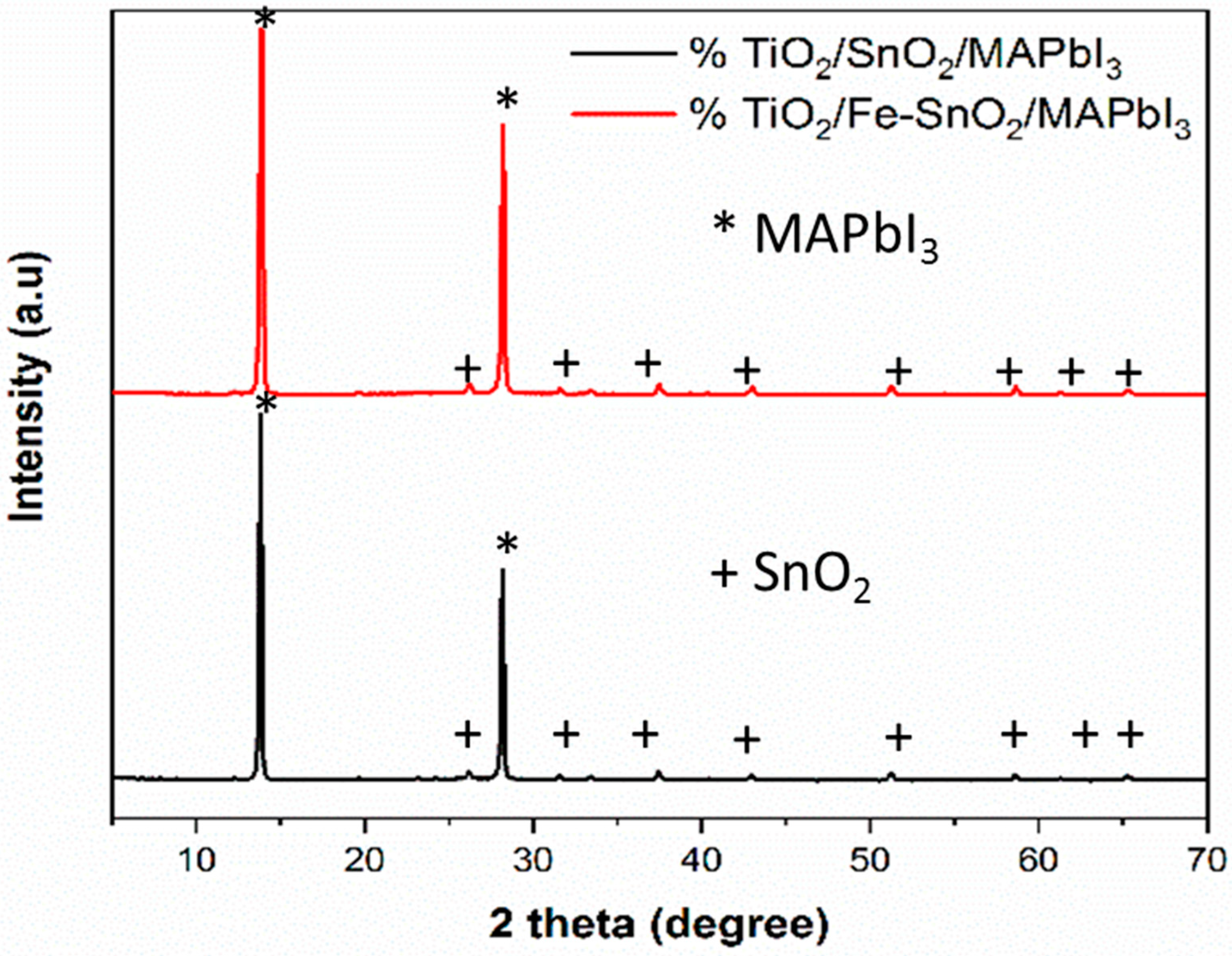
Figure 1 shows the XRD patterns of samples from devices 1 and 2. Assigned to the (110) and (220) planes, both samples exhibit the tetragonal MAPbI3 phase’s typical diffraction peaks, with powerful reflections at roughly 14.1° and 28.4°.The existence of PbI2 is ignored, as evidenced by the absence of a peak at 12.6°, indicating that the precursor has completely converted to the perovskite phase.
The Fe-doped SnO2-based sample (device 2) shows sharper and higher-intensity diffraction peaks than the undoped sample, indicating improved crystallinity and larger grain size of the perovskite layer. This increase demonstrates that Fe inclusion improves perovskite nucleation and development, revealing more efficient charge transfer and less trap-assisted recombination. Furthermore, the lack of additional peaks associated with Fe-based oxides suggests that Fe was efficiently absorbed into the SnO2 lattice without forming distinct crystalline phases.
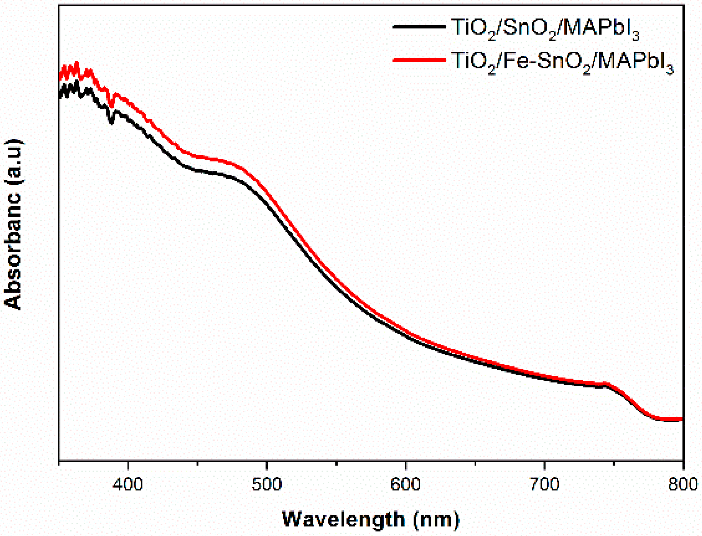
Figure 2 presents the UV-vis absorption spectra of devices 1 and 2. The wide and notable absorption band from 400 to 780 nm corresponds to MAPbI3 intrinsic optical absorption. Around 770–780 nm, there is an optical band gap of around 1.55 eV, suggesting that incorporating Fe into the SnO2 layer has no effect on the underlying electrical structure of the perovskite layer. In the visible range, the absorption spectra of device 2 (SnO2 doped with Fe) is slightly larger than that of device 1 (undoped). This improvement might come from a decrease in interfacial flaws or from Fe doping resulting in a more compact perovskite layer, which improves light capture efficiency. During the deposition process, no secondary phases or Fe-based contaminants were detected, as evidenced by the absence of another absorption peak.
The XRD patterns show improvement in the perovskite crystallinity, which leads to a reduction in the trap state density and the recombination of charges that enhance charge extraction. The UV-vis absorbance enhancement in the modified device exhibits enhancement in the perovskite layer morphology and good coverage.

2.2. Impedance Spectroscopy (Electrical Transport/Recombination)

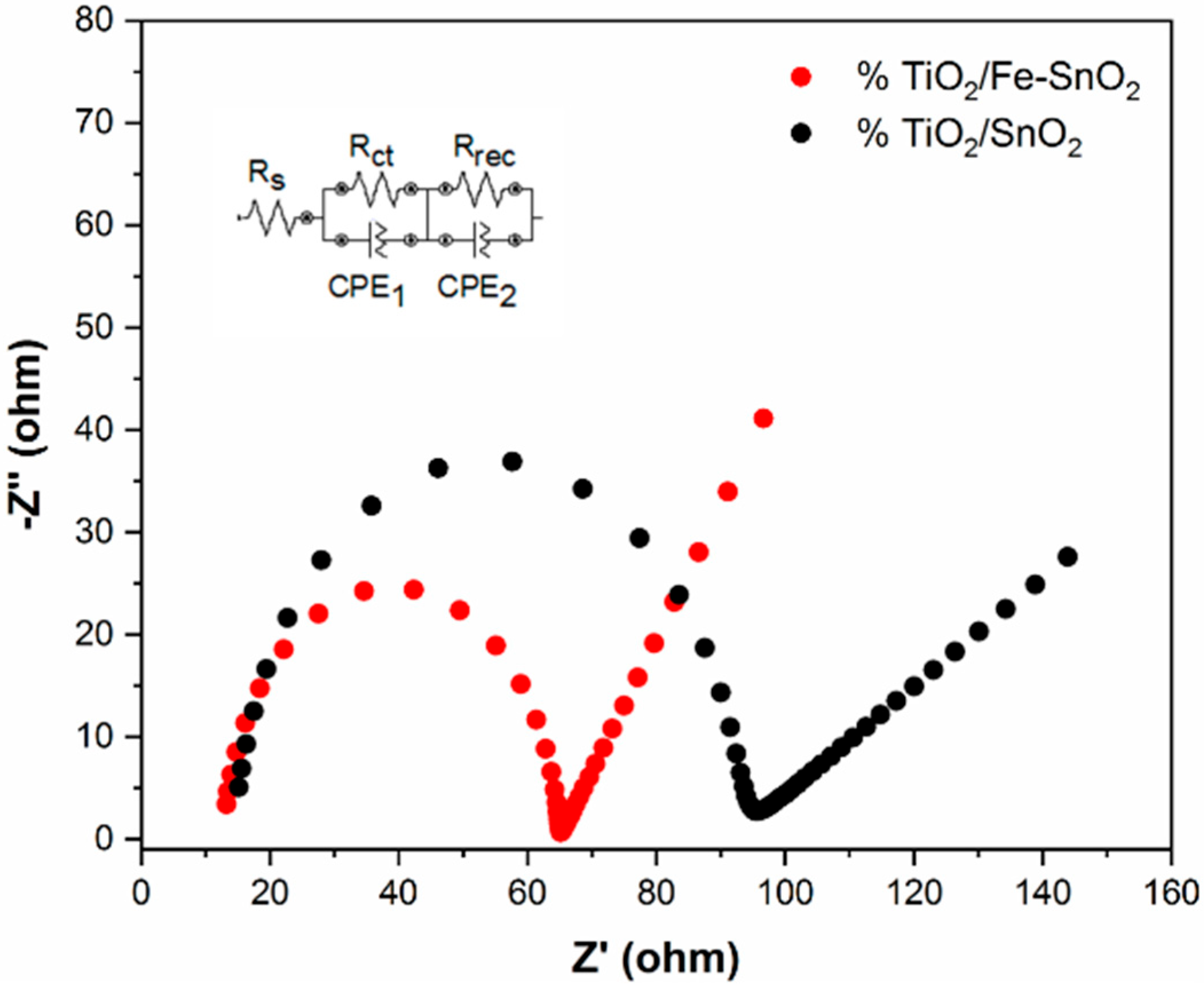
Figure 3 depicts the Nyquist plots for devices 1 and 2, as well as the analogous circuit used for fitting. The two curves show two semicircular arcs representing charge transport and recombination processes. The semicircle in the second device is smaller than in the first, indicating a significant drop in charge transfer resistance (Rct) and recombination resistance (Rrec).
This decrease shows that Fe doping increases electron extraction while decreasing interfacial recombination at the ETL/perovskite interface. Fe-SnO2 has increased electrical conductivity and energy-level alignment, leading to faster electron transport to the electrode and higher values of photovoltaic performance metrics, including fill factor (FF) and power conversion efficiency (PCE). With the Rs + (Rc//CPE1) + (Rrec//CPE2) circuit, the findings show that the Fe-SnO2 device has a reduced interfacial resistance, indicating improved optoelectronic capabilities, where 12.5 Ω was recorded for the modified device versus 14 Ω for the non-modified device. The TiO2/SnO2 bilayer structure with Fe doping enables reductions in oxygen vacancies in the TiO2 layer and trap density, as well as the perovskite layer to form in larger crystals that enhance the device’s performance, and reduce charge recombination, and facilitate charge extraction, improving the power conversion efficiency.

2.3. Device Performance

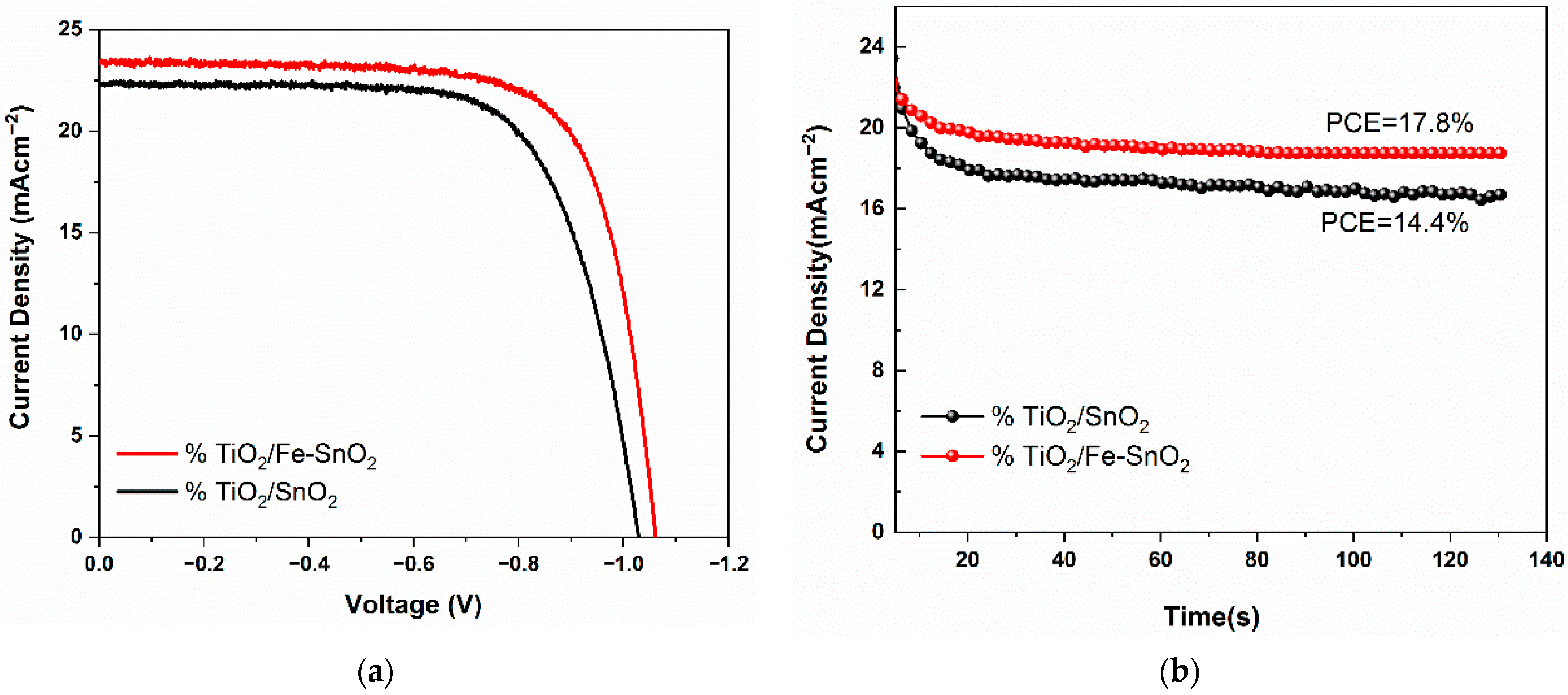
Figure 4a shows the steady-state J–V curves for both devices. The Fe-doped device (red curve) exhibits higher photocurrents and an improved fill factor relative to the undoped device (black curve), indicating that incorporating Fe into the SnO2 ETL favorably modifies the electronic interface. Fe3+ substitution in SnO2 can raise the SnO2 conduction band minimum (CBM) closer to the perovskite CB, reducing the band offset and increasing Voc. In addition, Fe may increase n-type conductivity in SnO2 (adding charge carriers) and reduce trap density, which lowers series resistance and nonradiative recombination. Together, these effects explain the larger current and higher Voc and FF seen in device 2.
Figure 4b plots the photocurrent density vs. time (seconds) under constant illumination or bias. Both devices quickly reach a steady current, but device 2 shows a slightly higher and more stable current. The lack of large transients suggests minimal hysteresis. The improved stability of the transient current in device 2 implies that Fe doping reduces carrier trapping at the SnO2/perovskite interface, yielding smoother charge extraction and less transient accumulation.

2.4. Aging and Light-Soaking Stability

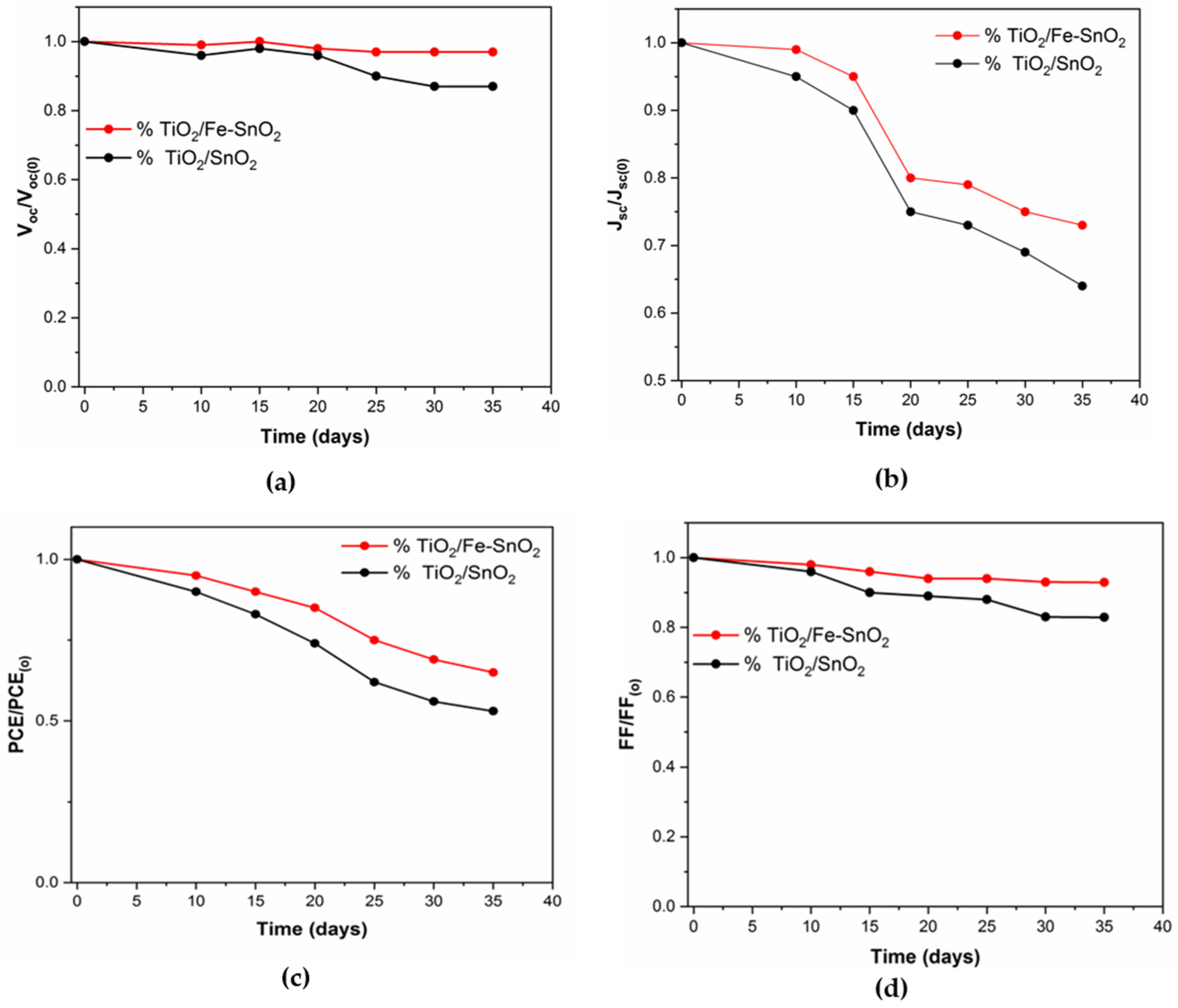
The fabricated devices were encapsulated in a sealed desiccator for the period of the stability analysis. The desiccator was kept at a low relative humidity (<10%) using fresh silica gel desiccant and maintained at room temperature in the dark. From time to time, the devices were taken for measurements and then directly returned to the desiccator to ensure the storage environment was kept consistent throughout the testing duration. Figure 5a–d track the relative decay of key parameters over several days of dark storage. In each case, the value is normalized to its initial (t = 0) value: Voc/Voc(0), Jsc/Jsc(0), PCE/PCE(0), and FF/FF(0) vs. time. For device 2, all curves decline more slowly than for device 1, showing that the Fe-doped cells retain a higher fraction of their initial performance with time. These trends imply that Fe doping stabilizes the device by passivating oxygen vacancies and other defect sites on the SnO2 surface.
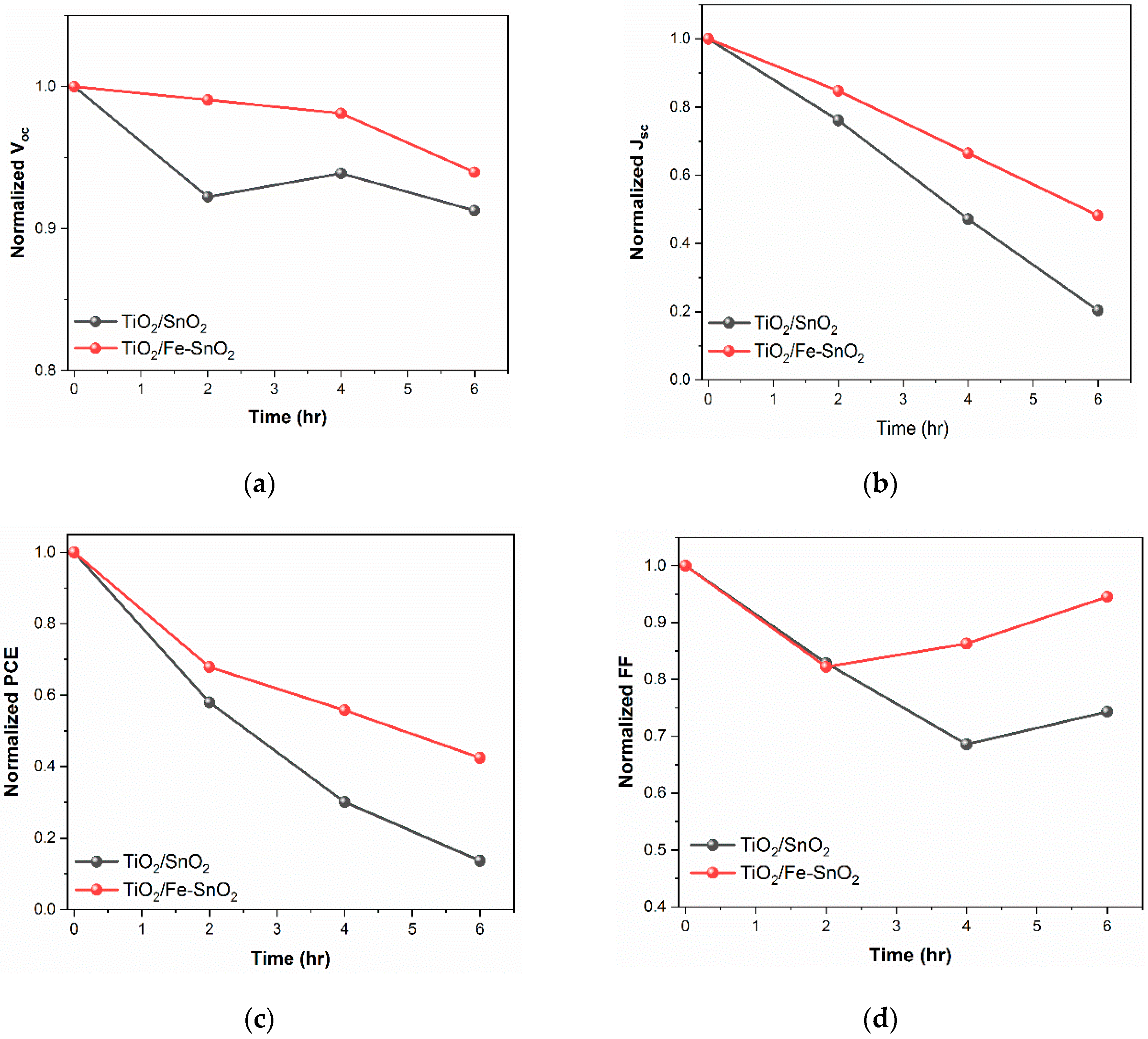
Figure 6a–d examine the devices under continuous illumination over the first few hours (normalized Voc, Jsc, PCE, and FF vs. time). Device 2 remains more stable, showing less initial burn-in and smaller decreases in efficiency parameters. This behavior is consistent with reduced trap-assisted recombination, as fewer interfacial traps mean that continuous light does not induce as many nonradiative paths, thereby retaining efficient levels of carrier extraction.

2.5. Effect of Fe Concentration

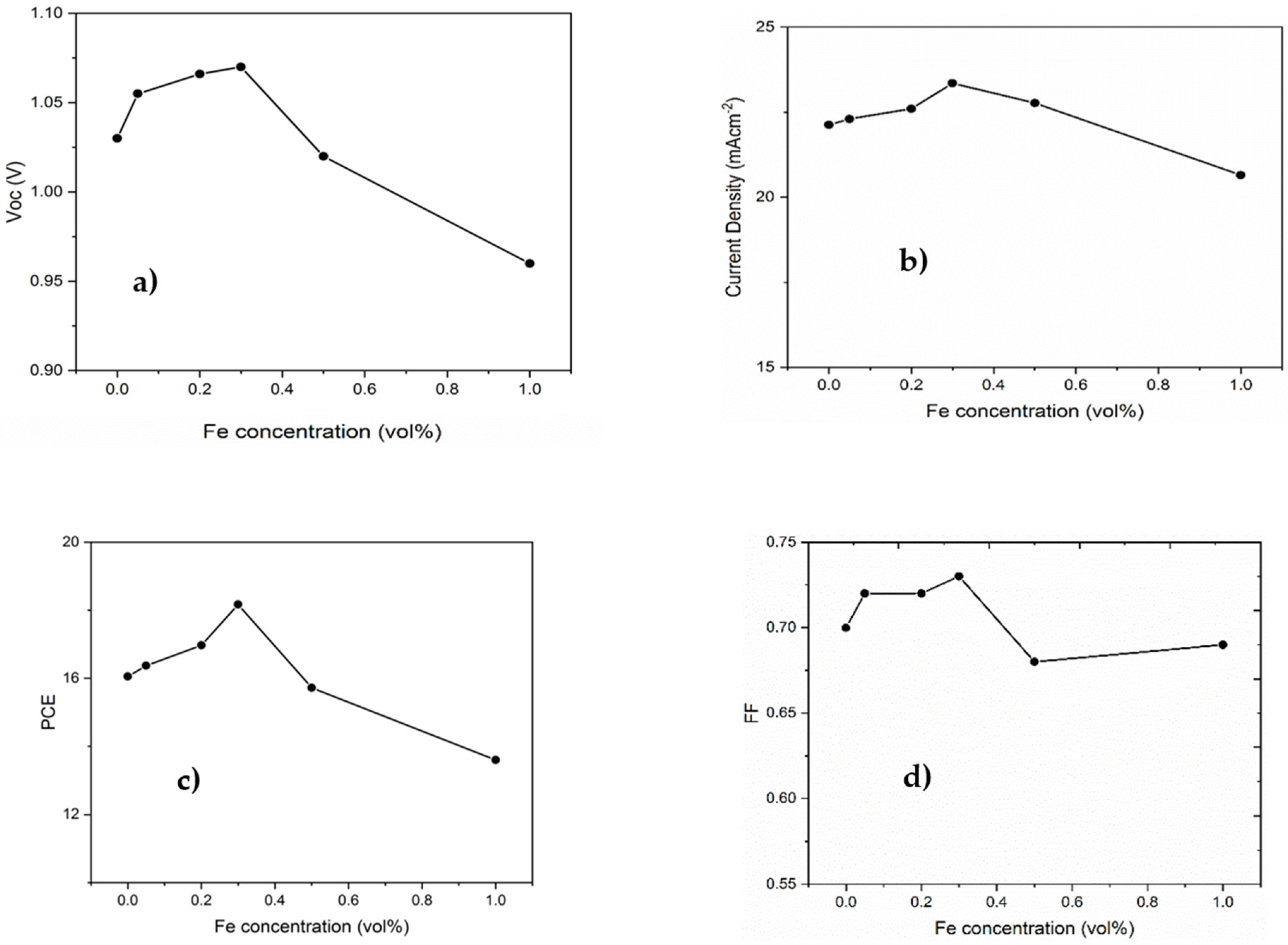
Figure 7a–d evaluate the key metrics against Fe concentration in the SnO2 layer. The PCE initially rises with Fe content, reaching a maximum at an optimal doping amount, and then declines at higher Fe amounts. This non-monotonic behavior is expected: light Fe doping provides beneficial effects (improved energy alignment, enhanced conductivity, defect passivation) that boost PCE, but excessive Fe introduces lattice disorder or deep traps that hurt performance. The optimal Fe concentration balances improved charge transfer against new defect formation.

2.6. Statistical Analysis

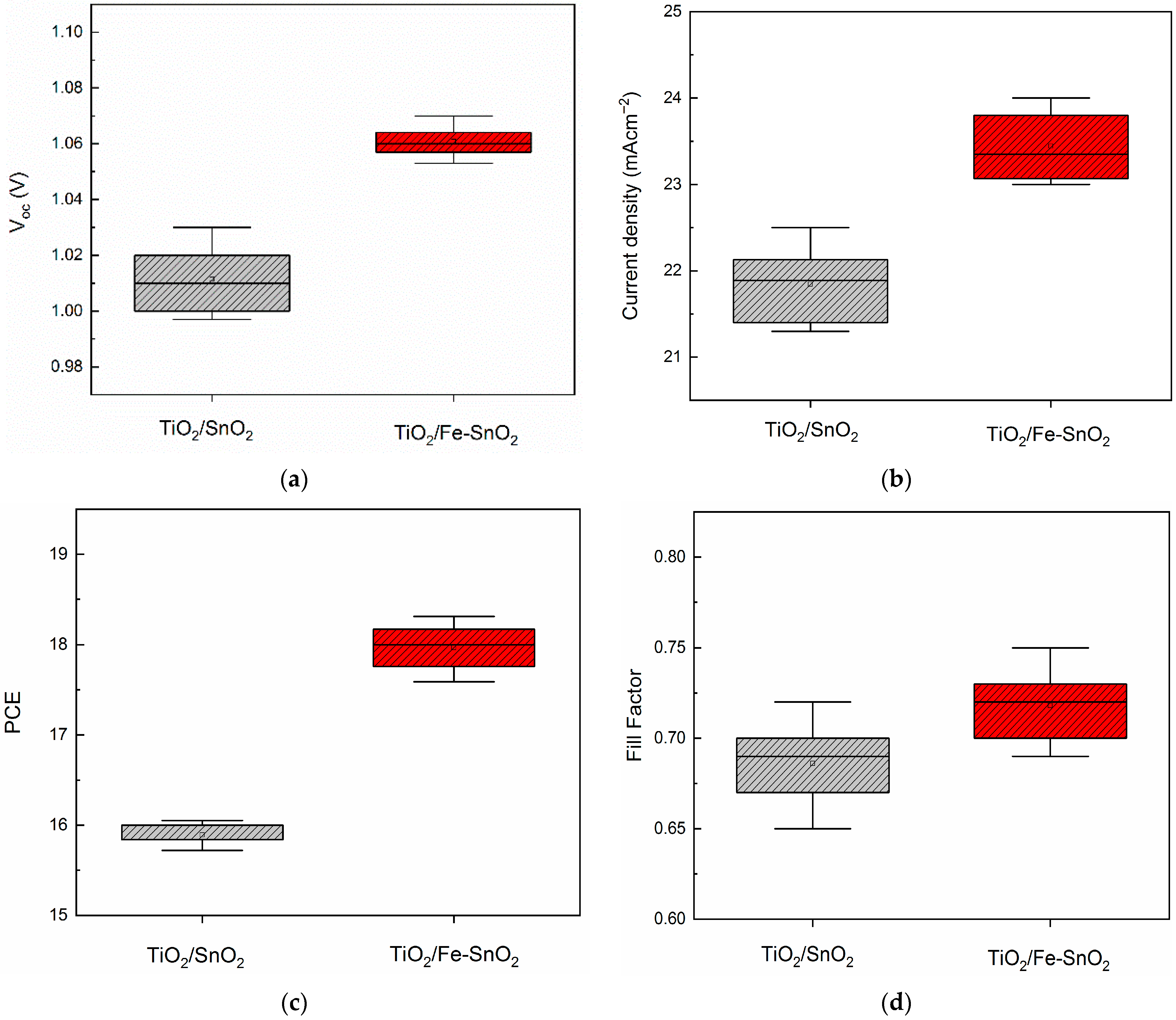
Figure 8a–d present statistical box plots comparing device 1 and device 2 over multiple samples (5 samples) with regard to Voc, Jsc, PCE, and FF. In every case, the Fe-doped cells show a higher median and smaller spread. The narrower distributions for device 2 suggest that Fe doping not only improves performance but also reproducibility, likely by making the ETL/perovskite interface more uniform.
Mechanistically, Fe modifies the SnO2 ETL structure and electronics. Substitutional Fe3+ in SnO2 likely introduces extra charge carriers or compensates for oxygen vacancies, raising the conduction band edge closer to the perovskite level. This reduces the Voc deficit and increases the built-in potential. Simultaneously, Fe dopants can passivate undercoordinated Sn or O sites on the SnO2 surface, effectively reducing the density of trap states that would otherwise capture electrons. Such defective passivation accelerates electron transport through the ETL and shrinks recombination losses.
In summary, Fe doping of the SnO2 ETL tunes both electronic energy levels and defect chemistry: it raises the ETL conduction band (boosting Voc), increases charge carrier density and mobility (raising Jsc and FF), and suppresses interface recombination (improving stability and hysteresis). These systematic enhancements are detected, and this study’s results demonstrate that balanced Fe incorporation can significantly improve carrier dynamics and device performance in SnO2-based perovskite solar cells by harmonizing the structural and electronic properties of the ETL.

3. Materials and Methods

3.1. Synthesis of High-Quality Perovskite Layers

3.1.1. FTO Glass Etching and Cleaning

FTO glass was cleaned after etching using Hellmanex. Afterward, a sonication path of ethanol, acetone, and isopropanol alcohol was set for 15 min at each stage to totally clean the FTO glass. A nitrogen gas flow was used for drying, and dust was removed via UV–ozone treatment for 15 min.

3.1.2. Titania Electron Transporting Layer Fabrication

The electron transport layer was placed over the fluorine tin oxide conductive glass (FTO) using the spin coating technique with which the TiO2 layer is first formed through the spin coating of titanium diisopropoxide bis (acetylacetonate) in ethanol (1:5 w/w) solution at 2000 rpm for 1 minute. Subsequently, the films were annealed in an oven at 150 °C for 10 min, and then at 500 °C for 45 min.
Secondly, a 1 mL of Tin(IV) oxide was added to 6.49 mL deionized water and stirred for 1 h to form a SnO2 solution. The SnO2 was deposited over the TiO2 layer at 5000 rpm/30 s, and then left to dry at 150 °C for 30 min over a hot plate in ambient air or in an oven followed by exposure to UV–ozone for 15 min before perovskite deposition. A total of 0.1 g of Fe (NO3)3∙9H2O was dissolved in 2 mL deionized water (50 mg/mL) and stirred for 3 h to form the Fe doping solution. The Fe source was chosen to be Fe(NO3)3∙9H2O based on the following: this salt is extremely solvable in water and readily mixes with the aqueous SnO2 precursor without producing organic solvents.
Then, 3 µL of this solution was added to 1 mL of SnO2 solution and stirred for at least 1 h to form the Fe-doped SnO2 solution, which was then deposited in the same manner on the pristine SnO2 layer.

3.1.3. Perovskite and Spiro-OMeTAD Preparation

At this step, the films were transferred to an argon-filled glovebox for perovskite and spiro layer deposition. The spin coating technique was used to deposit the perovskite layer over a titania layer in the glovebox. The perovskite films were dried over a hot plate to form the perovskite layer; afterward, the spiro layer was deposited by spin coating everything in the glovebox.
For the perovskite solution, 40 wt % of methylammonium iodide and lead acetate trihydrate was diluted in anhydrous DMF in a 3:1 molar ratio, and a small amount of hypophosphorous acid (50% w/w, aqueous solution) was added at the end. The perovskite solution was spin-coated on the ETLs at 2000 rpm for 45 s. The films obtained were left to dry at room temperature for 10 min and then annealed at 100 °C for 5 min. After cooling down, a 70 mM Spiro-MeOTAD solution in chlorobenzene, containing additives of lithium bis-(trifluoromethanesulfonyl) imide lithium salt in acetonitrile, 4-tert-butylpyridine and FK209 Co(III) TFSI salt in acetonitrile, was spin-coated at 4000 rpm for 10 s. Finally, 100 nm of patterned silver electrodes was thermally evaporated under a 10−6 Torr vacuum at a rate of 1 Å s−1. As a result, the final device comprised FTO/TiO2/SnO2/MAPbI3/Spiro-OMETAD/Ag as a reference device, while FTO/TiO2/SnO2 + Fe/MAPbI3/Spiro-OMETAD/Ag was the modified device.
The J-V curves were registered via Autolab potentiostat (Utrecht, The Netherlands, PGSTAT-302N) at a scan rate of 150 mV per second for both the forward and reverse scanning, and each batch had 6 cells.

4. Conclusions

This paper presents efficient, robust, and stable perovskite solar cells based on iron doping in the SnO2 electron transport layer of a bi-electron transport layer consisting of SnO2/TiO2. This study’s results reveal that the optimized iron concentration resulted in a clear enhancement of the modified device in comparison with the pristine one. This enhancement is due to the electron motion facilitation that causes a higher short circuit current and low charge recombination in the perovskite layer, leading to high power conversion efficiency.
The modified and reference devices were examined experimentally in the lab. As a result, a noticeable enhancement of the modified device was recorded in both efficiency and stability compared to that of the reference device. The experimental results reveal that the modified device has a short circuit current of 23.35 mA/cm2, open circuit voltage of 1.07 V, fill factor of 0.73, and high PCE of 18.17% while the reference device achieved only 22.13 mA/cm2, 1.03 V, 0.7, and 16.053%. Moreover, the results confirm that the iron-doped device was more stable than the pristine one under aging, thermal stress, and prolonged light tests.

Author Contributions

Conceptualization, S.A. and A.A.Z.; methodology, S.A., M.A., M.A.A. (Marc Al Atem), and A.A.Z.; software, S.A., M.A., M.A.A. (Marc Al Atem), and A.A.Z.; validation, S.A., M.A., M.A.A. (Marc Al Atem), M.A.A. (Mutaz A. Alanazi), B.Y., and A.A.Z.; formal analysis, S.A., M.A., M.A.A. (Marc Al Atem), M.A.A. (Mutaz A. Alanazi), B.Y., and A.A.Z.; investigation, S.A., M.A., M.A.A. (Marc Al Atem), M.A.A. (Mutaz A. Alanazi), B.Y., and A.A.Z.; writing—original draft preparation, M.A., M.A.A. (Marc Al Atem), S.A., and A.A.Z.; writing—review and editing, M.A., M.A.A. (Marc Al Atem), S.A., A.A.Z., M.A.A. (Mutaz A. Alanazi), and B.Y.; visualization, M.A., M.A.A. (Marc Al Atem), S.A., A.A.Z., M.A.A. (Mutaz A. Alanazi), and B.Y.; supervision, B.Y.; project administration, S.A.; funding acquisition, S.A. All authors have read and agreed to the published version of the manuscript.

Funding

This research was funded by Onaizah Colleges, Saudi Arabia, and the APC was funded by Onaizah Colleges, Saudi Arabia.

Institutional Review Board Statement

Not applicable.

Informed Consent Statement

Not applicable.

Data Availability Statement

The original contributions presented in this study are included in the article. Further inquiries can be directed to the corresponding author.

Acknowledgments

The authors express their sincere gratitude and appreciation to Onaizah Colleges, Saudi Arabia, for providing APC funding for this research.

Conflicts of Interest

The authors declare no conflicts of interest.

References

  1. Obaideen, K.; Abdelkareem, M.A.; Wilberforce, T.; Elsaid, K.; Sayed, E.T.; Maghrabie, H.M.; Olabi, A.G. Biogas role in achievement of the sustainable development goals: Evaluation, Challenges, and Guidelines. J. Taiwan Inst. Chem. Eng. 2022, 131, 104207. [Google Scholar] [CrossRef]
  2. Wilberforce, T.; Olabi, A.G.; Sayed, E.T.; Elsaid, K.; Maghrabie, H.M.; Abdelkareem, M.A. A review on zero energy buildings-Pros and cons. Energy Built Environ. 2021, 4, 25–38. [Google Scholar] [CrossRef]
  3. Arnaout, M.; Ismail, H.; Jaber, H.; Koubayssi, A.; Rammal, R.; Noun, Z. Study and Review on the Renewable Energy Potential in Lebanon. In Proceedings of the 2021 International Conference on Microelectronics (ICM), New Cairo City, Egypt, 19–22 December 2021; pp. 199–202. [Google Scholar]
  4. Zaky, A.A.; Christopoulos, E.; Gkini, K.; Arfanis, M.K.; Sygellou, L.; Kaltzoglou, A.; Stergiou, A.; Tagmatarchis, N.; Balis, N.; Falaras, P. Enhancing efficiency and decreasing photocatalytic degradation of perovskite solar cells using a hydrophobic copper-modified titania electron transport layer. Appl. Catal. B Environ. 2021, 284, 119714. [Google Scholar] [CrossRef]
  5. Solar Cells Efficiency Map. Available online: https://www.nlr.gov/pv/cell-efficiency (accessed on 28 March 2026).
  6. Kim, D.H.; Park, N.G. Advanced interface engineering for perovskite solar cells: The way to ensure efficiency and stability. Acc. Mater. Res. 2025, 6, 1147–1157. [Google Scholar] [CrossRef]
  7. Hu, R.; Chen, W.; Lai, J.; Li, F.; Qiao, H.; Liu, Y.; Qi, X. Heterogeneous Interface Engineering of 2D Black Phosphorus-Based Materials for Enhanced Photocatalytic Performance. Small 2025, 21, 2409735. [Google Scholar] [CrossRef]
  8. Nur-E-Alam, M.; Islam, M.S.; Abedin, T.; Islam, M.A.; Yap, B.K.; Kiong, T.S.; Khandaker, M.U. Current scenario and future trends on stability issues of perovskite solar cells: A mini review. Curr. Opin. Colloid Interface Sci. 2025, 76, 101895. [Google Scholar] [CrossRef]
  9. Wang, R.; Mujahid, M.; Duan, Y.; Wang, Z.-K.; Xue, J.; Yang, Y. A Review of Perovskites Solar Cell Stability. Adv. Funct. Mater. 2019, 29, 1808843. [Google Scholar] [CrossRef]
  10. Iqbal, M.Z.; Bibi, A.; Khan, S.; Chandra, S.; Kumar, A.; Kaushal, S.; Usmani, Y.S. Enhancing charge extraction efficiency in PbS-I quantum dot solar cell through optimized interface engineering. Sol. Energy 2025, 287, 113249. [Google Scholar] [CrossRef]
  11. Al Atem, M.; Makableh, Y.; Arnaout, M. Analytical Solutions for Current–Voltage Properties of PSCs and Equivalent Circuit Approximation. Eng 2025, 6, 62. [Google Scholar] [CrossRef]
  12. Marc, A.L.; Rezgui, B.D.; Touhami, I.; Bouaïcha, M. Numerical Simulation and Optimization of High-Performance Lead-based FAMACsPb (IBr)3 Perovskite Solar Cells Using SCAPS 1D. Results Eng. 2025, 29, 108555. [Google Scholar]
  13. Seyisi, T.; Fouda-Mbanga, B.G.; Mnyango, J.I.; Nthwane, Y.B.; Nyoni, B.; Mhlanga, S.; Tywabi-Ngeva, Z. Major challenges for commercialization of perovskite solar cells: A critical review. Energy Rep. 2025, 13, 1400–1415. [Google Scholar] [CrossRef]
  14. Al Atem, M.; Makableh, Y. Towards sustainable perovskite solar cells: Lead-free high efficiency designs with tin and germanium. Eng 2025, 6, 38. [Google Scholar] [CrossRef]
  15. Nowsherwan, G.A. Unraveling the photovoltaic behavior of Cs2NaBiI6 double perovskite: A combined DFT, SCAPS-1D, wxAMPS, COMSOL and machine learning approach. Opt. Quantum Electron. 2025, 58, 24. [Google Scholar] [CrossRef]
  16. Shimul, A.I.; Khan, M.A.; Rayhan, A.; Ghosh, A. Machine Learning-Based Optimization and Performance Enhancement of CH3NH3SnBr3 Perovskite Solar Cells with Different Charge Transport Materials Using SCAPS-1D and wxAMPS. Adv. Theory Simul. 2025, 8, 2500182. [Google Scholar] [CrossRef]
  17. Shimul, A.I.; Ghosh, A.; Ahmed, M.F.; Mugdho, A.S.; Hasan, Z.; Awwad, N.S.; Ibrahium, H.A. Investigating Optoelectronic Characteristics and Improving the Efficiency of Mg3AsBr3 Perovskite Solar Cells through Machine Learning and Numerical Simulations Utilizing Diverse Charge Transport Materials. Langmuir 2025, 41, 13655–13674. [Google Scholar] [CrossRef]
  18. Mahmud, S.; Islam, M.M.; Hossain, M.M.; Uddin, M.M.; Ali, M.A. Performance Engineering of Cs2AuScI6 Double Halide Perovskite Solar Cell: A DFT and SCAPS-1D Approach to 31.82% Efficiency. Adv. Theory Simul. 2026, 9, e01693. [Google Scholar] [CrossRef]
  19. Lachore, W.L.; Andoshe, D.M.; Mekonnen, M.A.; Hone, F.G. Recent progress in electron transport bilayer for efficient and low-cost perovskite solar cells: A review. J. Solid State Electrochem. 2022, 26, 295–311. [Google Scholar] [CrossRef]
  20. Gao, L.; He, Z.; Xu, C.; Su, Y.; Hu, J.; Ma, T. Systematic investigation of metal dopants and mechanism for the SnO 2 electron transport layer in perovskite solar cells. Phys. Chem. Chem. Phys. 2023, 25, 7229–7238. [Google Scholar] [CrossRef]
  21. Zhou, Y.; Guo, Y.; Yamauchi, Y.; Sugahara, Y. One-step synthesis of Fe-doped SnO2 mesoporous thin films with enhanced electron transfer and magnetic properties. Ceram. Int. 2025, 51, 37753–37760. [Google Scholar] [CrossRef]
  22. Guo, X.; Du, J.; Lin, Z.; Su, J.; Feng, L.; Zhang, J.; Hao, Y.; Chang, J. Enhanced efficiency and stability of planar perovskite solar cells using SnO2: InCl3 electron transport layer through synergetic doping and passivation approaches. Chem. Eng. J. 2021, 407, 127997. [Google Scholar] [CrossRef]
  23. Huy, H.; Pham, V.; Nguyen, T.M.H.; Bark, C.W. Recent advances of doped SnO2 as electron transport layer for high-performance perovskite solar cells. Materials 2023, 16, 6170. [Google Scholar]
  24. Kore, B.P.; Jamshidi, M.; Gardner, J.M. The impact of moisture on the stability and degradation of perovskites in solar cells. Mater. Adv. 2024, 5, 2200–2217. [Google Scholar] [CrossRef]
  25. Ye, J.; Li, Y.; Medjahed, A.A.; Pouget, S.; Aldakov, D.; Liu, Y.; Reiss, P. Enhanced performance of planar perovskite solar cells by doping the SnO2 electron transport layer with guanidinium chloride. Front. Mater. 2023, 10, 1118641. [Google Scholar] [CrossRef]
  26. Sun, X.; Li, L.; Shen, S.; Wang, F. TiO2/SnO2 bilayer electron transport layer for high efficiency perovskite solar cells. Nanomaterials 2023, 13, 249. [Google Scholar] [CrossRef]
  27. Qureshi, A.A.; Javed, S.; Akram, M.A.; Schmidt-Mende, L.; Fakharuddin, A. Solvent-assisted crystallization of an α-Fe2O3 electron transport layer for efficient and stable perovskite solar cells featuring negligible hysteresis. ACS Omega 2023, 8, 18106–18115. [Google Scholar] [PubMed]
  28. Wang, Y.; Ba, Z.; Dong, S.; Xie, W.; Wu, Z.; Ran, C. Advancing SnO2 electron transport layer for efficient perovskite photovoltaics: A critical review. ACS Appl. Mater. Interfaces 2025, 17, 27651–27670. [Google Scholar] [CrossRef] [PubMed]
  29. Yusuf, A.S.; Markwitz, M.; Chen, Z.; Ramezani, M.; Kennedy, J.V.; Fiedler, H. Review of progress in inorganic electron transport layers for perovskite solar cell applications. Appl. Phys. A 2025, 131, 859. [Google Scholar] [CrossRef]
Figure 1. X-ray diffraction (XRD) patterns of perovskite layer for device 1 (SnO2 undoped) and device 2 (SnO2 doped with Fe). Device 1’s perovskite layer thickness = ~480 ± 20 nm; device 2’s perovskite layer thickness = ~470 ± 25 nm. (The peaks in the figure are the peaks of perovskite.)
Inorganics 14 00118 g001
Figure 2. UV–Vis absorption spectra of perovskite films for device 1 (SnO2 undoped) and device 2 (SnO2 doped with Fe).
Inorganics 14 00118 g002
Figure 3. Electrochemical impedance spectroscopy (EIS) of device 1 (SnO2 undoped) and device 2 (SnO2 doped with Fe).
Inorganics 14 00118 g003
Figure 4. (a) Current density as function of voltage, (b) current density as function of time.
Inorganics 14 00118 g004
Figure 5. The effect of aging with respect to time on the normalized evaluation of (a) Voc, (b) Jsc, (c) PCE, and (d) FF.
Inorganics 14 00118 g005
Figure 6. The effect of the light-soaking stability on the normalized evaluation with respect to time of (a) Voc, (b) Jsc, (c) PCE, and (d) FF.
Inorganics 14 00118 g006
Figure 7. The correlation with Fe concentration for (a) Voc, (b) current density, (c) PCE, and (d) FF.
Inorganics 14 00118 g007
Figure 8. Statistical representations comparing device 1 and device 2 for 5 samples in terms of (a) Voc, (b) current density, (c) PCE, and (d) FF.
Inorganics 14 00118 g008
Table 1. Relevance studies for metal dopant perovskite cells.
Authors (et al.)—JournalYearTitleRef.Relevance (Brief)
L. Gao et al.—Phys. Chem. Chem. Phys.2023“Systematic investigation of metal dopants and mechanism for the SnO2 electron transport layer in perovskite solar cells”[20]Demonstrates various cation dopants (K, Na, etc.) in SnO2 ETLs; K doping improved efficiency (20.92% PCE) and stability.
Y. Zhou et al.—Ceramics Int.2025“One-step synthesis of Fe-doped SnO2 mesoporous thin films with enhanced electron transfer and magnetic properties”[21]Reports Fe incorporation in SnO2, showing that Fe-doped films have enhanced electron transfer capabilities while remaining transparent.
X. Guo et al.—Chem. Eng. J.2021“Enhanced efficiency and stability of planar perovskite solar cells using SnO2:InCl3 electron transport layer through synergetic doping and passivation approaches”[22]Combines ETL doping and interface passivation: InCl3-doped SnO2 ETL raised PCE from 19.1% to 20.8%, illustrating how ETL modification boosts performance.
V. P. H. Huy et al.—Materials2023“Recent Advances of Doped SnO2 as Electron Transport Layer for High-Performance Perovskite Solar Cells”[23]Review article summarizing SnO2 ETL properties and doping strategies (band alignment, mobility), providing broad context for SnO2 optimization.
B. P. Kore et al.—Mater. Adv.2024“The impact of moisture on the stability and degradation of perovskites in solar cells”[24]Review on PSC stability: highlights that perovskites decompose upon moisture exposure, emphasizing the need for protective strategies.
J. Ye et al.—Front. Mater.2023“Enhanced performance of planar perovskite solar cells by doping the SnO2 electron transport layer with guanidinium chloride”[25]Demonstrates how SnO2 ETL doped with guanidinium (Cl-containing) yields PCE up to 23.48% and excellent stability, showing chloride-based passivation benefits.
X. Sun et al.—Nanomaterials2023“TiO2/SnO2 Bilayer Electron Transport Layer for High Efficiency Perovskite Solar Cells”[26]Shows that a TiO2/SnO2 bilayer ETL increases perovskite grain size and PCE (17.64% vs. 16.16%), demonstrating the advantages of bilayer ETL architectures.
A. A. Qureshi et al.—ACS Omega2023“Solvent-Assisted Crystallization of an α-Fe2O3 Electron Transport Layer for Efficient and Stable Perovskite Solar Cells Featuring Negligible Hysteresis”[27]Uses α-Fe2O3 as an ETL: with optimized processing, 13% PCE and negligible hysteresis were obtained, outperforming SnO2 references and greatly improving device stability.
Y. Wang et al.—ACS Appl. Mater. Interfaces2025“Advancing SnO2 Electron Transport Layer for Efficient Perovskite Photovoltaics: A Critical Review”[28]Recent review emphasizes that SnO2’s chemical stability, low-temp processing, and band structure address charge transport and stability issues in PSCs.
A. S. Yusuf et al.—Appl. Phys. A2025“Review of progress in inorganic electron transport layers for perovskite solar cell applications”[29]Comprehensively reviews oxide ETLs (TiO2, ZnO, SnO2), highlighting their high mobility, transparency, and stability as key attributes for PSC ETLs.
Disclaimer/Publisher’s Note: The statements, opinions and data contained in all publications are solely those of the individual author(s) and contributor(s) and not of MDPI and/or the editor(s). MDPI and/or the editor(s) disclaim responsibility for any injury to people or property resulting from any ideas, methods, instructions or products referred to in the content.