Abstract
Poly[bis(4-phenyl) (2,5,6-trimethylphenyl) amine (PTAA), as a hole transfer material, has been widely used in perovskite solar cells (PSCs). However, the optimal solvent for preparing the PTAA solution and coating the PTAA layer is still uncertain. In this work, we investigated three types of organic solvents (toluene, chlorobenzene and dichlorobenzene) for processing PTAA layers as the hole transport layer in PSCs. Based on the experimental verification and molecular dynamics simulation results, all the evidence indicated that toluene performs best among the three candidates. This is attributed to the significant polarity difference between toluene and PTAA, which leads to the formation of a uniform surface morphology characterized by granular protuberances after spin coating. The contact area of the hole transfer layer with the surface aggregation is increased in reference to the rough surface, and the hydrophilicity of the PTAA layer is also increased. The improvement of these two aspects are conducive to the effective interfacial charge transfer. This leads to the generation of more photocurrent. The PSCs employing toluene-processed PTAA exhibit an average power conversion efficiency (PCE) of 19.1%, which is higher than that of PSCs using chlorobenzene- and dichlorobenzene-processed PTAA (17.3–17.9%). This work provides a direct optimization strategy for researchers aiming to fabricate PSCs based on PTAA as a hole transport layer and lays a solid foundation for the development of high-efficiency inverted PSCs.
1. Introduction
Recently, perovskite solar cells (PSCs) have become one of the most promising photovoltaic technologies due to their low production cost and simple preparation process [1,2,3,4,5,6,7,8,9]. The development of PSCs exceeds people’s expectation, and the power-conversion-efficiency (PCE), which increases by about 2.5% annually, keeps breaking the record [10,11,12,13]. At present, the efficiency of the highest certified single-layer PSCs has exceeded 27.0% [14]. Owing to their numerous advantages, PSCs have a very bright industrialization prospect and are therefore a potential competitor of next-generation solar cells. However, PSCs also suffer from some disadvantages, such as poor stability and lead toxicity, which limit their commercial applications [15,16].
PSCs usually have regular n-i-p and inverted p-i-n stack structures [12,13]. In such devices, perovskite materials are sandwiched between electron and hole transport layers. MAPbI3 (MA is methylammonium) is widely used as the energy conversion material of the perovskite layer; TiO2 and 2,2′,7,7′-Tetrakis[N,N-di(4-methoxyphenyl)amino]-9,9′-spirobifluorene (spiro-OMeTAD) are commonly used as electron and hole transport materials, respectively [15,16,17,18,19,20]. To further improve the performance and stability of PSCs, mix-cation perovskites have been developed, which include three cations of formamidinium (FA), MA and Cs [10]. Hole transfer materials such as poly(3,4-ethylenedioxythiophene):poly(styrenesulfonate) (PEDOT:PSS), nickel oxide, and poly[bis(4-phenyl)(2,5,6-trimethylphenyl)amine (PTAA) have been investigated in PSCs [21,22,23,24]. Although searching for new materials plays an important role in improving the performance of perovskite solar cells, controlling the morphology of each layer is also crucial to the performance of the devices [25,26,27,28]. For example, the morphology of perovskite films could directly affect the light absorption and charge generation [29,30,31,32]. The morphology of the electron and hole transport layer is of great significance for transport, separation and collection which affect the contact resistance and current density of the device [33,34]. Generally, in order to control the morphology of each functional layer, the commonly used methods are solvent optimization, thermal annealing and solvent annealing technology [22,35,36,37,38]. For example, in order to obtain a high-quality spiro-OMeTAD layer, spiro-OMeTAD is usually dissolved in chloroform, chlorobenzene or ethylacetate and then spin-coated. Similarly, controlling the morphology of the perovskite ore layer in devices by solvent treatment is frequently reported [39,40,41,42].
PTAA, as a kind of conductive polymer material, is increasingly being used to replace spiro-OMeTAD as the hole transport layer in perovskite solar cells [43,44,45,46,47]. This is because its lowest unoccupied molecular orbital (LUMO) levels (about −5.2 eV) can match well with the valence band of perovskite and the work function of ITO. In addition to energy level alignment, the contact between the hole transport layer and the perovskite absorber should also be optimized to more effectively extract holes from the perovskite and transport them to the anode. Jacak et al. demonstrated that using some nanometallic particles could enhance the hole capturing, which is beneficial for boosting the performance of PSCs [48]. Although in these reports, the devices using PTAA as the hole transfer layer have shown good performances. There is still no agreement on the solvents used in the treatment of PTAA in these reports [44,45,46,47]. Wu et al. [44] employed chlorobenzene as the solvent in their work, while Fu et al. and Deng et al. [46,47] used toluene. However, aside from the difference in PTAA solvents, other preparation conditions are not uniform, so it is difficult to decide which solvent is the best choice for the preparation of the PTAA coating liquid from their conclusions. This may cause some confusion for other researchers in the preparation of perovskite solar cells based on PTAA. In this work, we investigated the solvent effect for controlling the morphology of the PTAA layer, which further influences the performance of PSCs. We selected three solvents in the preparation of perovskite solar cells, i.e., toluene, chlorobenzene and dichlorobenzene, and carried out experimental and theoretical methods to obtain the data related to the device’s performance. We found that using toluene-processed PTAA resulted in the best performance for the PSCs, which exhibited an average PCE of 19.1%, whereas the PSCs using chlorobenzene or dichlobenzene-processed PTAA showed lower PCEs of 17.3% and 17.9%, respectively. The optimal solvent selection is illustrated by parameters such as molecular dynamics, surface morphology, hydrophobicity and device performance. Our work may provide an effect reference for other researchers in the future when they process a device with PTAA as the hole transfer layer.
2. Results and Discussion
As shown in Figure 1a, the PSCs were fabricated with a structure of glass/ITO/PTAA/perovskite/PCBM/BCP/Ag. As seen in the SEM image in Figure 1b, the PSCs have a standard layer-by-layer structure, with a perovskite thickness of about 500 nm. As indicated in the image, the processed PTAA and PCBM show thicknesses of about 30 and 65 nm, respectively. To find the indirect relationship between the solvent characteristics and the device performance, we used toluene, chlorobenzene and 1,2-dichlorobenzene as the coating solvent of PTAA to spin-coat the PTAA layer on ITO glass, using the same preparation method and conditions. To ensure the statistical validity of the related data, we prepared 15 samples for each group. The collected scatter statistical values of the photoelectric parameters of the samples are shown in the following figure (Figure 1).
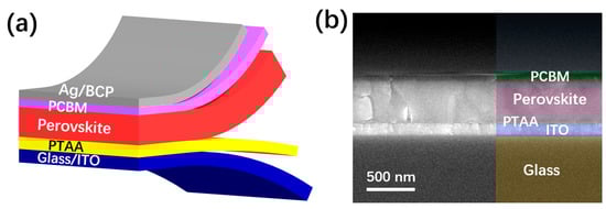
Figure 1.
(a) Schematic structure of the PSCs in this work. (b) Cross-sectional SEM image of the PSC.
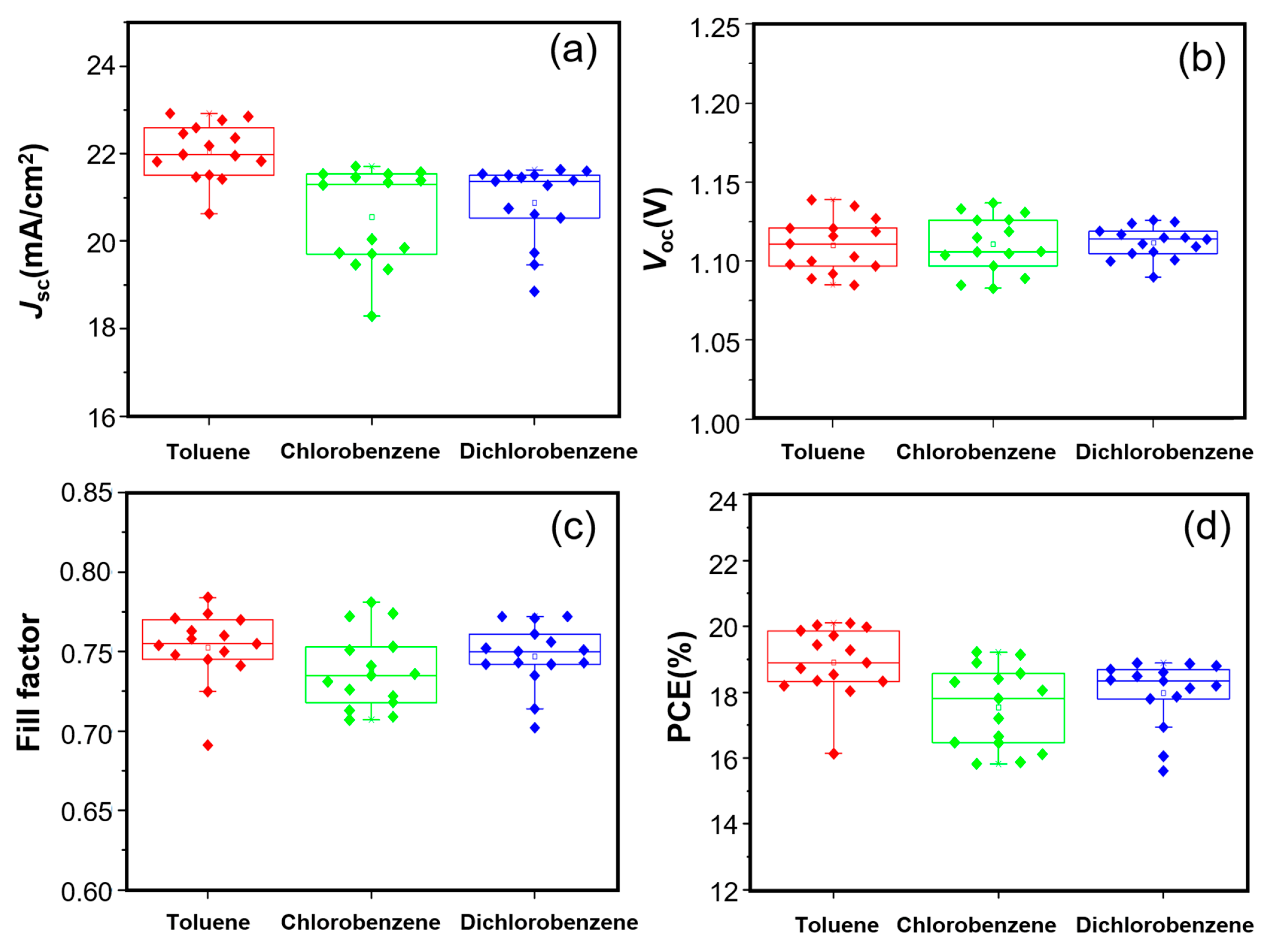
As shown in Figure 2a–d, the short-circuit current density (Jsc) and the PCE of the toluene-based group are obviously higher than those of the other two groups. In contrast, the open-circuit voltage (Voc) exhibit only minor variations among the three groups, with average values of 1.06 V, 1.05 V and 1.06 V, respectively. For the fill factor, no obvious change rule can be drawn from the three groups of data (0.71, 0.69 and 0.70 in average, respectively), This phenomenon will be discussed in detail later. If the influence of FF is temporarily disregarded, it can be inferred from the figure that the variation in Jsc is primarily determined by the choice of solvent, and the same applies to the PCE. Table 1 shows all the parameters, which were extracted from the forward scanning J–V characteristics. The PCEs (17.3–19.1%) in this work are lower than the record efficiency (about 27%). This may be related to the device’s configuration, the perovskite formula, the experimental conditions, etc. According to these data, it can be seen that for the Jsc, the device using toluene as solvent is superior to the other two groups. The trend of these values is in accordance with Figure 2a,b,d. For the fill factor, there are slight differences between the average values of the three groups and their best values. The results show that the PCE variation was mainly influence by the Jsc change, which affected the selection of the solvent.
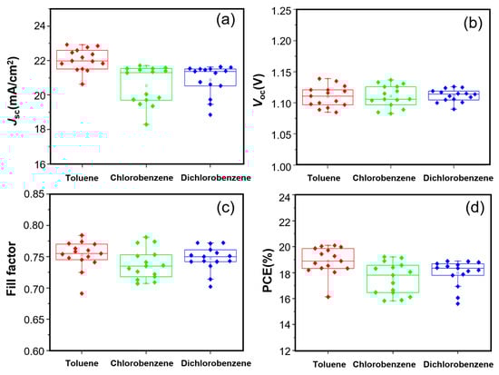
Figure 2.
Scatter statistics of the photoelectric parameters. (a), Jsc, (b), Voc, (c) fill factor, (d), PCE of the samples prepared by using the PTAA solution treated with toluene (red), chlorobenzene (green) and 1,2-dichlorobenzene (blue) as the electron transport layer of the spin-coating solution, with 15 samples for each group.

Table 1.
Device parameters for the PSCs based on PTAA processed from toluene, chlorobenzene and dichlorobenzene.
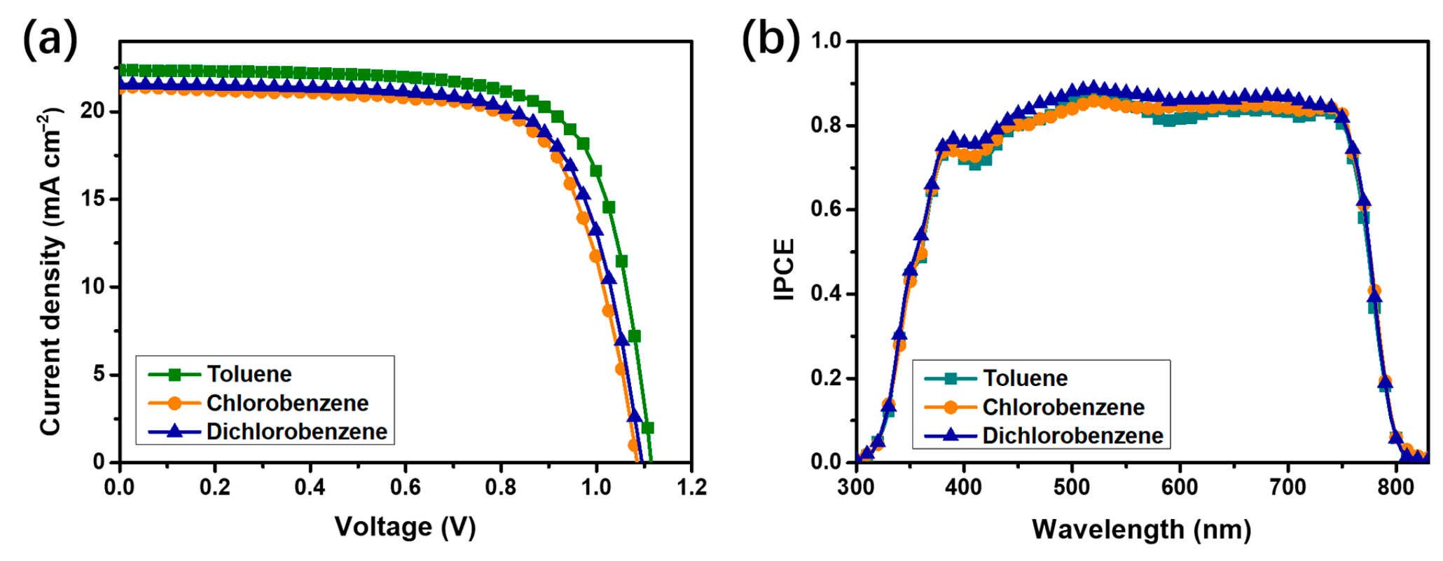
To further investigate the mechanism by which solvent selection influences device performance, we measured the J-V characteristics of PSCs, with PTAA layers processed using toluene, chlorobenzene and 1,2-dichlorobenzene. As shown in Figure 3a, the use of toluene as the processing solvent significantly enhances the Jsc as compared with chlorobenzene and 1,2-dichlorobenzene. However, the influence of the three solvents on the Voc is negligible, which is consistent with the aforementioned conclusion. Furthermore, to verify the reliability of the measured Jsc, we measured the IPCE spectra of the three best-performing devices and integrated the IPCE data over the entire wavelength range, as shown in Figure 3b. The integrated Jsc from the IPCE (on average) are 20.72, 19.48 and 19.42 mA/cm2 for the devices processed with toluene, chlorobenzene and 1,2-dichlorobenzene, respectively. These results are in good agreement with the current densities obtained from the J-V measurements, further confirming the reliability of our measurements.
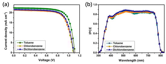
Figure 3.
J–V characteristics (a) and IPCE spectra (b) of the PSCs, with PTAA processed from toluene, chlorobenzene and dichlorobenzene.
Because the above evidence indicates that the Jsc is influenced by the choice of solvent, the following section will focus on analyzing the various factors affecting the Jsc of the devices in order to elucidate the underlying mechanism. As is well known, the generation of photocurrent in PSCs involves the following process: first, the perovskite layer absorbs photons, exciting the electrons, then the photogenerated electron–hole pairs are separated and transported to the electron transport layer and hole transport layer, respectively; finally, the charges are collected by the corresponding electrodes. In this process, the Jsc is closely associated with the photon absorption capability of the perovskite layer and the interfacial charge transfer efficiency between the perovskite and hole transport layers [21,23,24,25].
We investigated whether the photoelectron collection process can be influenced by the choice of solvent. According to previous studies, the crystallization and morphology of the perovskite’s active layer are critical factors in determining the efficiency of photoelectron collection [29,30]. We then characterized the perovskite films processed with the three solvents by X-Ray diffraction (XRD, Figure S1), scanning electron microscopy (SEM, Figure S2) and ultraviolet–visible absorption spectroscopy (UV–vis, Figure S3). The SEM images show that the morphology of the perovskite layer remains largely unaffected by the different solvent treatments. This can be explained as follows: during the preparation process, the thickness of the PTAA layer is much thinner than that of the perovskite layer. Moreover, as indicated in Figure 4, all the PTAA films processed from the different solvents showed a hydrophobic surface property. Therefore, variations in the PTAA layer do not significantly impact the surface morphology of the perovskite. However, the XRD and UV–vis absorption results indicate that the PSCs using toluene-processed PTAA exhibit the best performance. This aligns well with the FF results, strongly suggesting that the choice of organic solvent slightly affects the perovskite quality, although its impact on this is less significant than its impact on the charge transfer process.
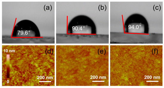
Figure 4.
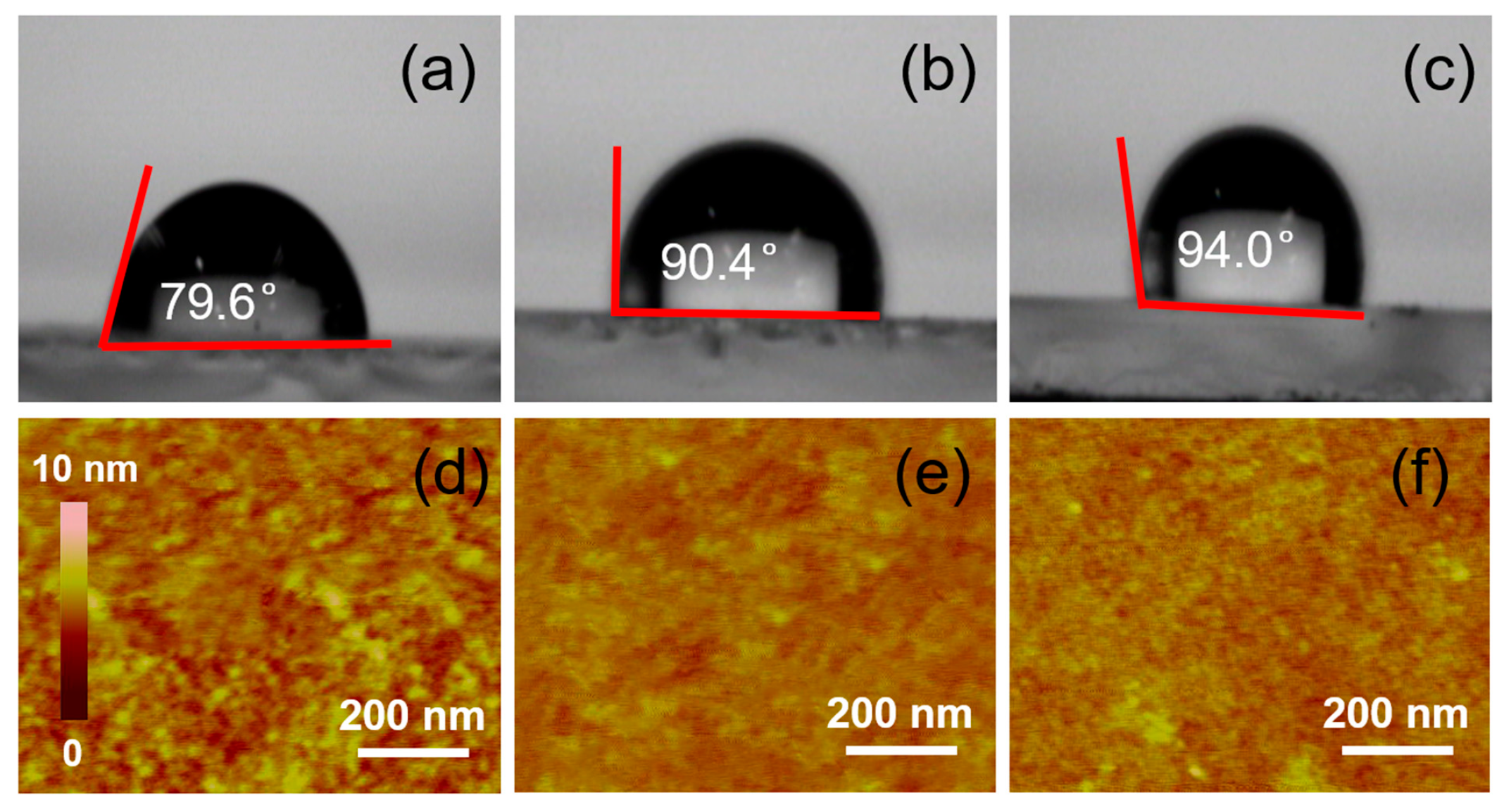
Contact angle of the PTAA layer prepared by using the PTAA solution treated with toluene (a), chlorobenzene (b) and 1,2-dichlorobenzene (c) and AFM images of the PTAA layer prepared by using the PTAA solution treated with toluene (d), chlorobenzene (e) and 1,2-dichlorobenzene (f), respectively.
To understand the influence of solvent selection on the interface charge transfer, we tested the surface morphology of the PTAA layer. First, the contact angles and atomic force microscopy (AFM) patterns of the PTAA layers, with toluene, chlorobenzene and 1,2-dichlorobenzene as solvents, were measured. Compared with Figure 4a–c, it can be seen that the contact angle of the PTAA layer with toluene is the smallest at 79.6°, while the contact angles of the PTAA surfaces with chlorobenzene and 1,2-dichlorobenzene as the solvents are more than 90° (90.4° and 94.0°, respectively), which indicates that the hydrophilicity of the PTAA layer can be obviously improved with toluene as the solvent. Then, atomic force microscopy was used to test their surface morphologies. AFM imaging (Figure 4d–f) shows the reason for the different hydrophobicity levels of the PTAA layers. Compared with the PTAA layers with chlorobenzene and 1,2-dichlorobenzene as solvents, the surface of the PTAA layer with toluene as the solvent shows obvious and dense protrusions, and the diameters of these protrusions are about 15 nm each. However, the surfaces of the PTAA layers with the other two solvents are much smoother, and almost no obvious protuberances can be seen. The RMS roughness values of the PTAA films processed from toluene, chlorobenzene and dichlorobenzene are 2.3, 1.8 and 1.6 nm, respectively. This phenomenon also corresponds to the contact angle obtained above. On the other hand, the existence of these protrusions is equivalent to increasing the interface area between the PTAA layer and the perovskite layer, which also increases the effective transfer probability of electrons between the interfaces, and this improvement can indeed improve the interfacial charge transfer efficiency. From the calculation mode of the dynamic simulations, the calculated interface area of the toluene-processed sample is 10.4%, which is 9.2% higher than that of the chlorobenzene- and 1,2-dichlorobenzene-processed samples. This conclusion is also consistent with the EIS (Figure S4) results, in which we tested the EIS to study the variation coursed by the different organic solution-treated PTAAs. Figure S4 shows the Nyquist plots with two characteristic arcs and equivalent circuits. The plots show that the recombination resistance (Rrec), the series resistance (Rs) and capacitor C can be observed. The toluene-treated sample exhibited an Rs of 26.3 Ω and an Rrec of 362.7 Ω, while the chlorobenzene and 1,2-dichlorobenzene-treated samples presented an Rs of 30.6 Ω with an Rrec of 477.5 Ω and an Rs of 29.3 Ω with an Rrec of 402.3 Ω, respectively. The decreased Rs and increased Rrec indicate the improved electron-transporting performance and suppressed charge recombination [40], which are conducive to an enhanced interface area and an enlarged Jsc.
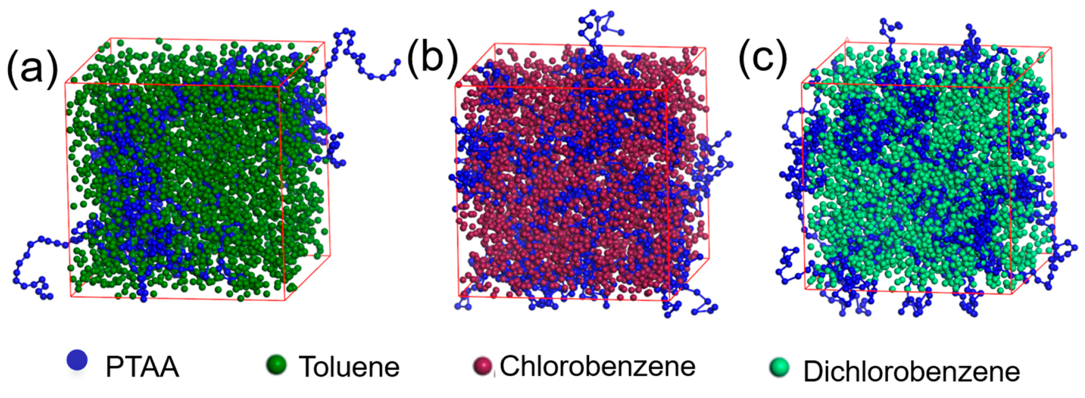
To investigate the origin of the surface protrusions observed in the AFM images, molecular dynamics simulations were conducted to analyze the distribution of PTAA molecular chains in different solvents. As shown in Figure 5, in toluene, the PTAA molecules tend to aggregate into large clusters due to their poor solubility, leading to an inhomogeneous distribution in the solution. This aggregation is likely due to the polarity difference between PTAA and toluene molecules (Table 2). Upon solvent evaporation, the aggregated state of PTAA is retained, leading to the formation of surface protrusions, as observed in the AFM images. Compared with toluene, PTAA molecules are more uniformly dispersed in the other two solvents, which accounts for the relatively smooth morphology of the PTAA layers formed using these solvents.

Figure 5.
Molecular dynamic simulation of the solvent and PTAA’s interaction mechanisms: toluene (a), chlorobenzene (b) and 1,2-dichlorobenzene (c).
Table 2.
The polarities of the solvents used in this work.
3. Materials and Methods
3.1. Materials
The patterned indium tin oxide (ITO) glass substrate and [6,6]-phenyl-C61 butyric acid methyl ester (PCBM) were purchased from Kaivo Co., Ltd. (Zhuhai, China) and Nano-C (Westwood, MA, USA), respectively. Methylammonium bromide (MABr), PTAA, FAI, cesium iodide (CsI) and lead bromide (PbBr2) were purchased from Xi’an Polymer Light Technology Corp. (Xi’an, China). Lead iodide (PbI2), bathocuproine (BCP) and all solvents [N,N-dimethylmethanamide (DMF), dimethylsulfoxide (DMSO), isopropanol, chlorobenzene, 1,2-dichlorobenzene and toluene] were supplied by Sigma-Aldrich (St. Louis, MO, USA).
3.2. Device Preparation
We employed Cs0.05FA0.81MA0.14PbI2.55Br0.45 perovskite as the absorber for photoelectric conversion. First, the etched ITO glass was washed in deionized water, acetone and isopropanol for 10 min and dried with a nitrogen gun. Next, clean ITO glass panels were treated in an ultraviolet ozone cleaner for 15 min. PTAA solutions (10 mg/mL in chlorobenzene, toluene or dichlorobenzene) were spin-coated onto the ITO glass substrates at 4000 r/min for 30 s. The spin-coated glass substrates were then annealed in air (140 °C, 15 min) to thoroughly evaporate the residual solvents. The perovskite precursor was prepared in a mix solvent (DMF:DMSO = 85:15) by dissolving FAI, MABr, CsI, PbI2 and PbBr2 into DMF [with molar ratios of PbI2/PbBr2 and FAI/MABr, both fixed at 0.85:0.15; CsI/(FAI + MABr) fixed at 0.05:0.95; and (FAI + MABr + CsI)/(PbI2 + PbBr2) fixed at 1:1)]. The final mass fraction was 40%. Before spin-coating, the perovskite precursor was heated and stirred for 12 h at 60 °C. The spin-coating of the perovskite and PCBM layers was accomplished in glove box filled with nitrogen: 150 μL perovskite solution was dripped on the spin-coated PTAA film and then spin-coated at 4500 r/min for 30 s. After spin-coating, the samples were heated for 10 min at 100 °C until the perovskite film completely changed from yellow to reddish brown.
Subsequently, PCBM was dissolved in chlorobenzene to prepare a 20 mg/mL solution. This PCBM solution was then dropped onto the formed perovskite film, spin-coated at 1000 rpm for 30 s and annealed at 40 °C for 10 min to remove the residual solvent. Finally, the spin-coated samples were transferred to a vacuum evaporator, where 0.6 nm of BCP was deposited at a rate of 0.2–0.3 Å/s under a vacuum pressure below 1 × 10⁻⁵ Torr. Subsequently, 100 nm thick Ag electrodes were deposited at a rate of 1–2 Å/s. Subsequently, the device was encapsulated using ultraviolet-cured epoxy resin and a glass cover slide, after which its performance was evaluated. The effective active area of the PSCs was 0.04 cm2.
3.3. Characterizations
The J–V characteristic curve of the solar cells were tested under 1 sunlight intensity (100 MW/cm), and the Keithley 2400 was used to collect data. The incident photon-to-current efficiency (IPCE) spectra of the PSCs were measured by a SolarCellScan100 (Zolix, Beijing, China). The cross-sectional image of the PSCs and the morphology of the perovskite layer were measured by using a SEM (SU8020, Tokyo, Japan) with an acceleration voltage of 8000 V. The contact angles were measured by dropping water onto the surface of the PTAA films. The morphologies of the PTAA films were measured by an AFM (Veeco, San Jose, CA, USA) in the tapping mode.
3.4. Simulation Background
In the Mesocite module of Quantum Espresso (QE) 7.4, we used the dissipative particle dynamics method to study the effect of the solvent. A cubic hypermonomer with a transverse dimension of 100 Å × 100 Å × 100 Å was used, which contained 7750 PTAA monomers and 2461 solvent molecules. The average density of PTAA was 1.09 g cm−3. Newton’s equations of motion were integrated by using the Verlet algorithm with a time step of 1 fs. The simulated temperature and pressure were set to 413.15 K (140 °C) and 101.325 kPa (1atm), respectively.
4. Conclusions
In conclusion, we systematically investigated three different organic solvents (toluene, chlorobenzene and dicholobenzene) for processing PTAA layers as the hole transport layer in perovskite solar cells. Both the experimental results and molecular dynamics simulations reveal that PTAA exhibits significant molecular aggregation in toluene, whereas such aggregation is not observed in the cases of chlorobenzene and dichlorobenzene. The evaporation of different solvents resulted in distinct surface morphologies of the PTAA layers. On one hand, the formation of surface protrusions increases the interfacial area for excited-state charge transfer, thereby enhancing the probability of efficient hole transport and improving the current density of the device. On the other hand, the roughened surface enhances the hydrophilicity of the PTAA layer, which is beneficial for achieving higher device efficiency. Although different solvents influence the morphology of the PTAA layer, this morphological variation plays a key role in determining device performance. Our study demonstrates that the choice of PTAA solvent has a significant influence on the properties of the perovskite layer. The above evidence indicates that toluene is the most suitable solvent for processing PTAA in perovskite solar cells.
Supplementary Materials
The following supporting information can be downloaded at https://www.mdpi.com/article/10.3390/inorganics13070232/s1, Figure S1: XRD patterns of the perovskite layers; Figure S2: Top-view SEM images of the perovskite layers; Figure S3: Absorption spectra of the peroskite layers; Figure S4: EIS spectra of the devices.
Author Contributions
Conceptualization, X.X. and Z.L.; methodology, X.L. (Xi Liu); investigation, C.D.; resources, X.X.; data curation, H.Y. and E.-C.L.; writing—original draft preparation, X.X.; writing—review and editing, Z.L.; visualization, C.D.; supervision, G.L. and Z.L.; project administration, G.L.; funding acquisition, X.L. (Xueyi Liu). All authors have read and agreed to the published version of the manuscript.
Funding
This research was funded by Hubei Provincial Key R&D Program Projects, NO.: 2023DJC187 and the Hubei Provincial Natural Science Foundation Project, NO.: 2024AFD003; Hubei Polytechnic University Research Foundation, No.: ky2025-119; Hubei Provincial Natural Science Foundation of China, No. 2025AFB357.
Data Availability Statement
All relevant data are contained within the manuscript and its Supplementary Materials files.
Conflicts of Interest
The authors declare no conflicts of interest, and the funders had no role in the design of the study; in the collection, analyses, or interpretation of data; in the writing of the manuscript; or in the decision to publish the results.
Abbreviations
The following abbreviations are used in this manuscript:
| PTAA | Poly[bis(4-phenyl) (2,5,6-trimethylphenyl) amine |
| PSCs | perovskite solar cells |
| HOMO | highest occupied molecular orbital |
| LUMO | lowest unoccupied molecular orbital |
| PCE | power conversion efficiency |
| IPCE | incident photon to current efficiency |
References
- Zhou, H.; Chen, Q.; Li, G.; Luo, S.; Song, T.; Duan, H.S.; Hong, Z.; You, J.; Liu, Y.; Yang, Y. Interface engineering of highly efficient perovskite solar cells. Science 2014, 345, 542–546. [Google Scholar] [CrossRef] [PubMed]
- Lee, M.M.; Teuscher, J.; Miyasaka, T.; Murakami, T.N.; Snaith, H.J. Efficient Hybrid Solar Cells Based on Meso-Superstructured Organometal Halide Perovskites. Science 2012, 338, 643–647. [Google Scholar] [CrossRef] [PubMed]
- Yang, W.S.; Park, B.W.; Jung, E.H.; Jeon, N.J.; Kim, Y.C.; Lee, D.U.; Shin, S.S.; Seo, J.; Kim, E.K.; Noh, J.H.; et al. Iodide management in formamidinium-lead-halide–based perovskite layers for efficient solar cells. Science 2017, 356, 1376–1379. [Google Scholar] [CrossRef]
- Yang, W.S.; Noh, J.H.; Jeon, N.J.; Kim, Y.C.; Ryu, S.; Seo, J.; Seok, S.I. High-performance photovoltaic perovskite layers fabricated through intramolecular exchange. Science 2015, 348, 1234–1237. [Google Scholar] [CrossRef]
- Zhang, X.; Ren, X.; Liu, B.; Munir, R.; Zhu, X.; Yang, D.; Li, J.; Liu, Y.; Smilgies, D.M.; Li, R.; et al. Stable high efficiency two-dimensional perovskite solar cells via cesium doping. Energy Environ. Sci. 2017, 10, 2095–2102. [Google Scholar] [CrossRef]
- Hu, X.; Wang, H.; Wang, M.; Zang, Z. Interfacial defects passivation using fullerene-polymer mixing layer for planar-structure perovskite solar cells with negligible hysteresis. Sol. Energy 2020, 206, 816–825. [Google Scholar] [CrossRef]
- Grancini, G.; Roldán-Carmona, C.; Zimmermann, I.; Mosconi, E.; Lee, X.; Martineau, D.; Narbey, S.; Oswald, F.; De Angelis, F.; Graetzel, M.; et al. One-Year stable perovskite solar cells by 2D/3D interface engineering. Nat. Commun. 2017, 8, 15684. [Google Scholar] [CrossRef]
- El-Ballouli, A.O.; Bakr, O.M.; Mohammed, O.F. Structurally Tunable Two-Dimensional Layered Perovskites: From Confinement and Enhanced Charge Transport to Prolonged Hot Carrier Cooling Dynamics. J. Phys. Chem. Lett. 2020, 11, 5705–5718. [Google Scholar] [CrossRef] [PubMed]
- Zhong, Y.; Hufnagel, M.; Thelakkat, M.; Li, C.; Huettner, S. Role of PCBM in the Suppression of Hysteresis in Perovskite Solar Cells. Adv. Funct. Mater. 2020, 30, 1908920. [Google Scholar] [CrossRef]
- Xie, Y.; Yu, H.; Duan, J.; Xu, L.; Hu, B. Enhancing Device Performance in Quasi-2D Perovskite ((BA)2(MA)3Pb4I13) Solar Cells Using PbCl2 Additives. ACS Appl. Mater. Interfaces 2020, 12, 11190–11196. [Google Scholar] [CrossRef]
- Gong, X.; Wang, Y.; Kuang, T. ZIF-8-Based Membranes for Carbon Dioxide Capture and Separation. ACS Sustain. Chem. Eng. 2017, 5, 11204–11214. [Google Scholar] [CrossRef]
- Li, Y.; Miao, P.; Zhou, W.; Gong, X.; Zhao, X. N-doped carbon-dots for luminescent solar concentrators. J. Mater. Chem. A 2017, 5, 21452–21459. [Google Scholar] [CrossRef]
- Shen, C.; Courté, M.; Krishna, A.; Tang, S.; Fichou, D. Quinoidal 2,2′,6,6′-Tetraphenyl-Dipyranylidene as a Dopant-Free Hole-Transport Material for Stable and Cost-Effective Perovskite Solar Cells. Energy Technol. 2017, 5, 1852–1858. [Google Scholar] [CrossRef]
- Green, M.A.; Dunlop, E.D.; Yoshita, M.; Kopidakis, N.; Bothe, K.; Siefer, G.; Hao, X.; Jiang, J.Y. Solar Cell Efficiency Tables (Version 66). Prog. Photovoltaics 2025, 33, 795–810. [Google Scholar] [CrossRef]
- Tsai, H.; Nie, W.; Blancon, J.C.; Stoumpos, C.C.; Asadpour, R.; Harutyunyan, B.; Neukirch, A.J.; Verduzco, R.; Crochet, J.J.; Tretiak, S.; et al. High-efficiency two-dimensional Ruddlesden–Popper perovskite solar cells. Nature 2016, 536, 312–316. [Google Scholar] [CrossRef] [PubMed]
- Zhang, X.; Munir, R.; Xu, Z.; Liu, Y.; Tsai, H.; Nie, W.; Li, J.; Niu, T.; Smilgies, D.; Kanatzidis, M.G.; et al. Phase Transition Control for High Performance Ruddlesden–Popper Perovskite Solar Cells. Adv. Mater. 2018, 30, 1707166. [Google Scholar] [CrossRef]
- Cao, D.H.; Stoumpos, C.C.; Farha, O.K.; Hupp, J.T.; Kanatzidis, M.G. 2D Homologous Perovskites as Light-Absorbing Materials for Solar Cell Applications. J. Am. Chem. Soc. 2015, 137, 7843–7850. [Google Scholar] [CrossRef]
- Zhang, X.; Wu, G.; Fu, W.; Qin, M.; Yang, W.; Yan, J.; Zhang, Z.; Lu, X.; Chen, H. Orientation Regulation of Phenylethylammonium Cation Based 2D Perovskite Solar Cell with Efficiency Higher Than 11%. Adv. Energy Mater. 2018, 8, 1702498. [Google Scholar] [CrossRef]
- Chen, Y.; Sun, Y.; Peng, J.; Zhang, W.; Su, X.; Zheng, K.; Pullerits, T.; Liang, Z. Tailoring Organic Cation of 2D Air-Stable Organometal Halide Perovskites for Highly Efficient Planar Solar Cells. Adv. Energy Mater. 2017, 7, 1700162. [Google Scholar] [CrossRef]
- Ma, C.; Shen, D.; Ng, T.W.; Lo, M.F.; Lee, C.S. 2D Perovskites with Short Interlayer Distance for High-Performance Solar Cell Application. Adv. Mater. 2018, 30, 1800710. [Google Scholar] [CrossRef]
- Stoumpos, C.C.; Cao, D.H.; Clark, D.J.; Young, J.; Roudinelli, J.M.; Jang, J.I.; Hupp, J.T.; Kanatzidis, M.G. Ruddlesden–Popper Hybrid Lead Iodide Perovskite 2D Homologous Semiconductors. Chem. Mater. 2024, 20, 2405953. [Google Scholar] [CrossRef]
- Mann, D.S.; Thakur, S.; Sangale, S.S.; Jeong, K.-U.; Kwon, S.-N.; Na, S.-I. Interfacial engineering of nickel oxide-perovskite interface with amino acid complexed NiO to improve perovskite solar cell performance. Small 2015, 8, 1602–1608. [Google Scholar] [CrossRef] [PubMed]
- Wang, Y.; Duan, L.; Hameiri, Z.; Liu, X.; Bai, Y.; Hao, X. PTAA as efficient hole transport materials in perovskite solar cells: A review. Sol. RRL 2022, 6, 2200234. [Google Scholar] [CrossRef]
- Lim, K.G.; Ahn, S.; Kim, Y.H.; Qi, Y.; Lee, T.W. Universal energy level tailoring of self-organized hole extraction layers in organic solar cells and organic–inorganic hybrid perovskite solar cells. Energy Environ. Sci. 2016, 9, 932–939. [Google Scholar] [CrossRef]
- Kim, H.; Lim, K.G.; Lee, T.W. Planar heterojunction organometal halide perovskite solar cells: Roles of interfacial layers. Energy Environ. Sci. 2016, 9, 12–30. [Google Scholar] [CrossRef]
- Xie, X.; Liu, G.; Xu, C.; Li, S.; Liu, Z.; Lee, E.C. Tuning the work function of indium-tin-oxide electrodes for low-temperature-processed, titanium-oxide-free perovskite solar cells. Org. Electron. 2017, 44, 120–125. [Google Scholar] [CrossRef]
- Liu, Y.; Yang, Z.; Cui, D.; Ren, X.; Sun, J.; Liu, X.; Zhang, J.; Wei, Q.; Fan, H.; Yu, F.; et al. Two-Inch-Sized Perovskite CH3NH3PbX3 (X = Cl, Br, I) Crystals: Growth and Characterization. Adv. Mater. 2015, 27, 5176–5183. [Google Scholar] [CrossRef] [PubMed]
- Luo, D.; Zhao, L.; Wu, J.; Hu, Q.; Zhang, Y.; Xu, Z.; Liu, Y.; Liu, T.; Chen, K.; Yang, W.; et al. Dual-Source Precursor Approach for Highly Efficient Inverted Planar Heterojunction Perovskite Solar Cells. Adv. Mater. 2017, 29, 1604758. [Google Scholar] [CrossRef]
- Dong, Q.; Fang, Y.; Shao, Y.; Mulligan, P.; Qiu, J.; Cao, L.; Huang, J. Electron-hole diffusion lengths > 175 μm in solution-grown CH3NH3PbI3 single crystals. Science 2015, 347, 967–970. [Google Scholar] [CrossRef]
- Wang, Z.B.; Helander, M.G.; Greiner, M.T.; Qiu, J.; Lu, Z.H. Analysis of charge-injection characteristics at electrode-organic interfaces: Case study of transition-metal oxides. Phys. Rev. B 2009, 80, 235325. [Google Scholar] [CrossRef]
- Liu, Z.; Xie, X.; Lee, E.C. Effects of organic solvents for the phenyl-C61-butyric acid methyl ester layer on the performance of inverted perovskite solar cells. Org. Electron. 2018, 56, 247–253. [Google Scholar] [CrossRef]
- Leijtens, T.; Eperon, G.E.; Noel, N.K.; Habisreutinger, S.N.; Petrozza, A.; Snaith, H.J. Stability of Metal Halide Perovskite Solar Cells. Adv. Energy Mater. 2015, 5, 1500963. [Google Scholar] [CrossRef]
- Liu, G.; Xie, X.; Zeng, F.; Liu, Z. Improving the Performance of Perovskite Solar Cells Through Solvent Vapor Annealing-based Morphology Control of the Hole-Transport Layer. Energy Technol. 2018, 6, 1283–1289. [Google Scholar] [CrossRef]
- Kim, B.J.; Kim, D.H.; Lee, Y.Y.; Shin, H.W.; Han, G.S.; Hong, J.S.; Mahmood, K.; Ahn, T.K.; Joo, Y.C.; Hong, K.S.; et al. Highly efficient and bending durable perovskite solar cells: Toward a wearable power source. Energy Environ. Sci. 2015, 8, 916–921. [Google Scholar] [CrossRef]
- Chen, L.; Xie, X.; Liu, Z.; Lee, E.C. A transparent poly(3,4-ethylenedioxylenethiophene):poly(styrene sulfonate) cathode for low temperature processed, metal-oxide free perovskite solar cells. J. Mater. Chem. A 2017, 5, 6974–6980. [Google Scholar] [CrossRef]
- Chen, W.; Zhang, Q. Recent progress in non-fullerene small molecule acceptors in organic solar cells (OSCs). J. Mater. Chem. C 2017, 5, 1275–1302. [Google Scholar] [CrossRef]
- Lin, Y.; Wang, J.; Zhang, Z.G.; Bai, H.; Li, Y.; Zhu, D.; Zhan, X. An Electron Acceptor Challenging Fullerenes for Efficient Polymer Solar Cells. Adv. Mater. 2015, 27, 1170–1174. [Google Scholar] [CrossRef] [PubMed]
- Bin, H.; Zhang, Z.G.; Gao, L.; Chen, S.; Zhong, L.; Xue, L.; Yang, C.; Li, Y. Non-Fullerene Polymer Solar Cells Based on Alkylthio and Fluorine Substituted 2D-Conjugated Polymers Reach 9.5% Efficiency. J. Am. Chem. Soc. 2016, 138, 4657–4664. [Google Scholar] [CrossRef]
- Lin, Y.; Zhao, F.; He, Q.; Huo, L.; Wu, Y.; Parker, T.C.; Ma, W.; Sun, Y.; Wang, C.; Zhu, D.; et al. High-Performance Electron Acceptor with Thienyl Side Chains for Organic Photovoltaics. J. Am. Chem. Soc. 2016, 138, 4955–4961. [Google Scholar] [CrossRef]
- Xie, X.; Liu, G.; Cheng, G.; Liu, Z.; Lee, E.C. Improving performance of organic solar cells by supplying additional acceptors to surface of bulk-heterojunction layers. J. Mater. Chem. C 2018, 6, 2793–2800. [Google Scholar] [CrossRef]
- Liu, Z.; Lee, E.C. Solvent engineering of the electron transport layer using 1,8-diiodooctane for improving the performance of perovskite solar cells. Org. Electron. 2015, 24, 101–105. [Google Scholar] [CrossRef]
- Li, S.; Ye, L.; Zhao, W.; Zhang, S.; Mukherjee, S.; Ade, H.; Hou, J. Energy-Level Modulation of Small-Molecule Electron Acceptors to Achieve over 12% Efficiency in Polymer Solar Cells. Adv. Mater. 2016, 28, 9423–9429. [Google Scholar] [CrossRef] [PubMed]
- Qin, P.; Tetreault, N.; Dar, M.; Gao, P.; Call, K.L.M.; Rutter, S.R.; Ogier, S.D.; Forrest, N.D.; Bissett, J.S.; Simms, M.J.; et al. A Novel Oligomer as a Hole Transporting Material for Efficient Perovskite Solar Cells. Adv. Energy Mater. 2015, 5, 1400980. [Google Scholar] [CrossRef]
- Wu, Y.; Wang, P.; Wang, S.; Wang, Z.; Cai, B.; Zheng, X.; Chen, Y.; Yuan, N.; Ding, J.; Zhang, W.H. Heterojunction Engineering for High Efficiency Cesium Formamidinium Double-Cation Lead Halide Perovskite Solar Cells. Chemsuschem 2017, 5, 11. [Google Scholar]
- Song, J.; Li, J.; Xu, L.; Li, J.; Zhang, F.; Han, B.; Shan, Q.; Zeng, H. Room-Temperature Triple-Ligand Surface Engineering Synergistically Boosts Ink Stability, Recombination Dynamics, and Charge Injection toward EQE-11.6% Perovskite QLEDs. Adv. Mater. 2018, 30, 1800764. [Google Scholar] [CrossRef]
- Deng, Y.; Zheng, X.; Bai, Y.; Wang, Q.; Zhao, J.; Huang, J. Surfactant-controlled ink drying enables high-speed deposition of perovskite films for efficient photovoltaic modules. Nat. Energy 2018, 3, 560–566. [Google Scholar] [CrossRef]
- Fu, F.; Feurer, T.; Weiss, T.P.; Pisoni, S.; Avancini, E.; Andres, C.; Buecheler, S.; Tiwari, A.N. High-efficiency inverted semi-transparent planar perovskite solar cells in substrate configuration. Nat. Energy 2016, 2, 16190. [Google Scholar] [CrossRef]
- Jacak, J.E.; Jacak, W.A. Routes for Metallization of Perovskite Solar Cells. Materials 2022, 15, 2254. [Google Scholar] [CrossRef]

Disclaimer/Publisher’s Note: The statements, opinions and data contained in all publications are solely those of the individual author(s) and contributor(s) and not of MDPI and/or the editor(s). MDPI and/or the editor(s) disclaim responsibility for any injury to people or property resulting from any ideas, methods, instructions or products referred to in the content. |
© 2025 by the authors. Licensee MDPI, Basel, Switzerland. This article is an open access article distributed under the terms and conditions of the Creative Commons Attribution (CC BY) license (https://creativecommons.org/licenses/by/4.0/).