Abstract
Amorphous carbon and its heteroatom-doped derivatives often exhibit wrinkled, defective, porous structures, and find wide applications in the fields of energy storage and catalysis. To date, although many methods for preparing doped carbon materials have been reported, the preparation process is relatively complex, and there are still few simple methods available. Therefore, it is necessary to further develop simple and feasible preparation methods. In this study, we employed commercially available manganese disodium ethylenediaminetetraacetate (EDTA-Na2Mn, serving as both carbon and nitrogen sources) as the precursor. Through thermal decomposition under a nitrogen atmosphere, a nitrogen-doped carbon composite embedded with manganese monoxide (MnO) was initially obtained. Subsequently, hydrochloric acid etching was applied to remove the MnO phases, yielding the final product: nitrogen-doped carbon, denoted as C-N-Mn. Notably, the carbonization and nitrogen-doping processes were simultaneously accomplished during pyrolysis, thereby streamlining the synthesis route for nitrogen-doped carbons. To demonstrate the versatility of this approach, we extended the methodology to two additional metal–organic salts (EDTA-Na2Zn and EDTA-NaFe), successfully synthesizing nitrogen-doped carbon materials (C-N-Zn and C-M-Fe) in both cases. The phase composition, morphology, microstructure, specific surface area, and pore volume of the products were systematically characterized using X-ray diffraction (XRD), scanning/transmission electron microscopy (SEM/TEM), Raman spectroscopy, X-ray photoelectron spectroscopy (XPS), and nitrogen adsorption/desorption analysis. These nitrogen-doped carbons exhibit high specific surface areas and tunable pore volumes, suggesting their potential applicability in energy storage systems.
1. Introduction
Amorphous carbon, including soft carbon, hard carbon, and soft/hard composite carbon, has drawn continuous and widespread attention in the fields of energy storage [1,2,3,4,5], CO2 adsorption [6,7,8,9], energy conversion [10,11,12], and photocatalysis [13,14,15] due to its porous structure, high specific surface area, stable physicochemical properties, and environmental friendliness. Therefore, the synthesis of porous carbon materials is particularly important. Currently, there are mainly two preparation methods, namely template and template-free methods [16,17,18]. Template methods include soft template [19,20] and hard template [21,22,23]. Soft template mainly utilizes block copolymers and surfactants as structure-directing agents to synthesize porous carbon materials. The steps of preparing porous carbon via hard template method can be summarized as follows: 1. composite of carbon precursor and template; 2. high-temperature carbonization process; 3. removal of the template. For example, Zhang et al. [23] used monodisperse Fe3O4 nanospheres as a template and glucose as a carbon source to obtain a Fe3O4-C composite through high-temperature carbonization. After corrosion of the thermal nitric acid, nitrogen-doped porous carbon nanospheres were obtained and used as negative electrode materials for lithium storage. In addition, porous carbon materials can also be obtained by direct carbonization of the organometallic compounds (template-free method). For instance, Li et al. [24] first synthesized rod-shaped copper tartrate (micrometer scale) through hydrothermal synthesis, then carbonized the precursor to obtain Cu-C composites, before finally corroding the Cu-C product with thermal nitric acid to remove the copper. As a result, nitrogen-doped porous carbon materials were obtained, and their lithium storage performance was tested.
The two researchers first synthesized carbon materials and then doped nitrogen using hot nitric acid corrosion. Recent reports showed that nitrogen-doped carbon can be produced via high-temperature pyrolysis of nitrogen-containing biomass (lotus seed pot biomass) [8] or polymers (polyacrylonitrile fiber) [9], proving the feasibility of simultaneous carbonization and nitrogen doping. However, our research finds few reports on using cheap, stable nitrogen-containing organic small molecules (e.g., disodium ethylenediaminetetraacetate) as precursors for nitrogen-doped carbon synthesis. Thus, in this study, commercial and relatively inexpensive ethylenediaminetetraacetic acid disodium manganese (serving as C, N, Mn, and O sources simultaneously) was used as the raw material, mixed with sodium chloride in a 1:1 ratio, and then subjected to high-temperature pyrolysis under an inert atmosphere in a tube furnace to obtain MnO-C-N composites. After hydrochloric acid corrosion, nitrogen-doped porous carbon materials were obtained. We have extended this method, for example, to carbonization of ethylenediaminetetraacetic acid disodium zinc, ethylenediaminetetraacetic acid sodium iron, etc., which can all yield nitrogen-doped porous carbon materials, and the potassium storage performances of these three products were tested. The innovation of this article is mainly reflected in the preparation of materials as follows: (i) abandoning the complex preparation process; (ii) choosing carbon and nitrogen homologs of organic metal compounds with moderate prices and stable properties as precursors; (iii) pyrolysis of the commercialized precursors can be carried out to achieve the simultaneous completion of carbonization and nitrogen doping, thereby simplifying the synthesis steps; (iv) the metal compounds in the product obtained after pyrolysis can be easily corroded with dilute hydrochloric acid, which will add more porous structures to the carbon materials. Of course, this simple and controllable synthesis method can also be used inthe preparation of other carbon materials.
2. Results
Figure 1 illustrates the synthesis of nitrogen-doped carbon. Ethylenediaminetetraacetic acid disodium manganese was mixed with sodium chloride in a 1:1 ratio, followed by uniform ball milling. Subsequently, the mixture was subjected to 700 °C heat treatment under a nitrogen atmosphere for 4 h, resulting in a black product (composite of carbon-coated MnO, denoted as MnO-C-N). After mild hydrochloric acid corrosion, a nitrogen-doped amorphous carbon film (denoted as C-N-Mn) was obtained. The preparation procedure for the other two carbon materials (C-N-Fe, C-N-Zn) was similar to that of C-N-Mn. Sodium chloride acted as a thermal conductivity medium, a carrier for the melted organometallic salt, and a hard template for pore formation. To calculate the yield of the N-doped carbon, we repeated the experiment (Figures S7 and S8). Based on the experimental results, we can calculate the actual yield of carbon. The theoretical yield of carbon is calculated using the formula: (12*10*0.95)/389.13. Here, 389.13 is the molecular weight of sodium manganese(II) ethylenediaminetetraacetate, 12 is the molar mass of carbon, 10 is the number of carbon atoms in each molecule of sodium manganese(II) ethylenediaminetetraacetate, and 0.95 is the purity of the reagent. Calculations show that the theoretical yield of carbon is 0.293. Therefore, when 3 g of the reagent is weighed, the theoretical yield of carbon is 0.879 g. The actual mass of carbon obtained was 0.19 g, so the actual yield of carbon is: (0.19/0.879)*100% = 21.6%.
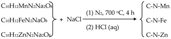
Figure 1.
Synthetic route to prepare N-doped carbon materials (C-N-Mn, C-N-Fe, and C-N-Zn).
Figure S1 shows the XRD diffraction patterns of the product after the thermal decomposition of ethylenediaminetetraacetic acid disodium manganese. The diffraction peaks correspond well to the standard card (PDF no. 07-0230), indicating the cubic phase of MnO without significant impurity peaks. The diffraction peaks of amorphous carbon are not obvious, suggesting much lower intensity compared to MnO. The product after the thermal decomposition of ethylenediaminetetraacetic acid disodium iron is a composite of iron, iron nitride, and carbon (denoted as Fe/Fe3N/Fe4N-C-N), as shown in Figure S2 (PDF no. 06-0696 for Fe, PDF no. 49-1663 for Fe3N, and PDF no. 06-0627 for Fe4N). According to the metal activity series (as shown in Table S1), manganese is more active than zinc, which is more active than iron. Thus, the stability of the oxides is in the order: MnO > ZnO > FeO. FeO is easier to reduce than MnO and ZnO. At 700 °C with carbon present, iron oxides are first reduced by carbon to form iron, while oxygen combines with carbon to form COx gas, which is then carried away by the inert gas flow. Since the precursor contains nitrogen (more electronegative than carbon), some iron combines with nitrogen to form iron nitrides (Figure S2). MnO and ZnO, being more stable, are not reduced by carbon at 700 °C and remain. The product after the thermal decomposition of ethylenediaminetetraacetic acid disodium zinc is pure ZnO phase (denoted as ZnO-C-N), as shown in Figure S3 (PDF no. 36-1451). After hydrochloric acid corrosion, all three thermal decomposition products became amorphous carbon materials, with only a weak peak observed at the (002) crystal plane.
The morphology of the samples was observed by SEM and TEM. MnO-C-N exhibited a structure of carbon-coated MnO particles (Figure 2(a1,a3)). After corrosion, it transformed into carbon flakes (Figure 2(a2,a4)). The morphologies of Fe/Fe3N/Fe4N-C-N (Figure 2(b1,b3)) and ZnO-C-N (Figure 2(c1,c3)) were similar to that of MnO-C-N. After corrosion, they also turned into amorphous carbon films (Figure 2(b2,b4,c2,c4)).
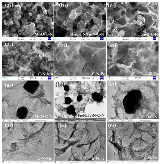
Figure 2.
SEM and TEM images of the samples. (a1,a3) (MnO-C-N), (a2,a4) (C-N-Mn); (b1,b3) (Fe/Fe3N/Fe4N-C-N), (b2,b4) (C-N-Fe); (c1,c3) (ZnO-C-N), (c2,c4) (C-N-Mn).
The EDS spectra and elemental mapping of each sample are shown in Figure 3a,b (C-N-Mn), Figure S4 (MnO-C-N), Figure 3c,d (C-N-Fe), Figure S5 (Fe/Fe3N/Fe4N-C-N), Figure 3e,f (C-N-Zn), and Figure S6 (ZnO-C-N). Each element is uniformly dispersed in the samples and found in the EDS spectra.
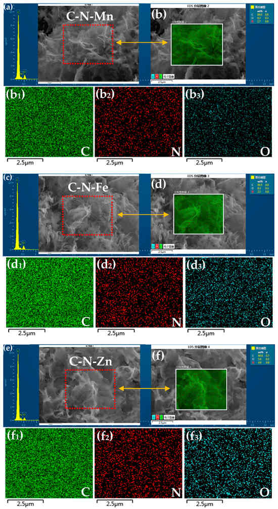
Figure 3.
(a) EDS spectrum of the C-N-Mn sample and elemental mapping (b) of C (b1), N (b2), and O (b3); (c) EDS spectrum of the C-N-Fe sample and elemental mapping (d) of C (d1), N (d2), and O (d3); (e) EDS spectrum of the C-N-Zn sample and elemental mapping (f) of C (f1), N (f2), and O (f3).
Figure 4a shows the XRD patterns of the prepared three samples. Only one broad and weak peak around 25° was found in each sample, which corresponds to (002) plane of graphite and indicates the low degree of graphitization of the samples. The Raman spectroscopy was used to analyze the crystalline structure of carbon materials. As shown in Figure 5, the Raman spectra of C-N-Mn, C-N-Fe, and C-N-Zn show D and G peaks of around 1350 cm−1 and 1590 cm−1, representing disordered and graphitic carbon structures, respectively. Because the peak width of the D- and G-band is very different, we calculated the (ID/IG)A ratio based on the area under the D- and G-band, as well as using the intensity ratio ID/IG (Figure 5a), to analyze the defect extent of the carbon material. As shown in Figure 5b–d, the (ID/IG)A of C-N-Mn, C-N-Fe, and C-N-Zn were 2.75, 3.2, and 2.72, respectively. The integral area ratio confirms the presence of more defects in the carbon materials [2].
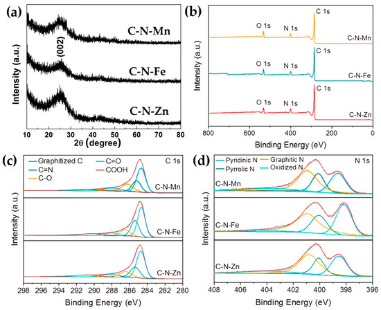
Figure 4.
(a) XRD of the three samples; (b) XPS survey spectra of C-N-Mn, C-N-Fe, and C-N-Zn; (c) high-resolution C 1s spectrum of C-N-Mn, C-N-Fe, and C-N-Zn; (d) high-resolution N 1s spectrum of C-N-Mn, C-N-Fe, and C-N-Zn.
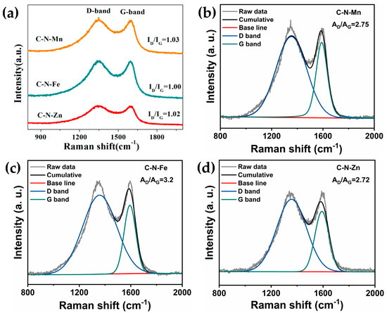
Figure 5.
Raman spectra of (a) the three samples; (b) C-N-Mn; (c) C-N-Fe; (d) C-N-Zn.
X-ray photoelectron spectroscopy (XPS) measurements of samples were performed. As shown in Figure 4b, the XPS survey spectra for the samples shows peaks at C 1s, N 1s of the doped N, and O 1s. The results show that the atomic percentage of doped N in C-N-Mn, C-N-Fe, and C-N-Zn is about 10.9%, 10.6%, and 11.6%, respectively. Deconvolution of the high-resolution C 1s spectrum (Figure 4c) gives five peaks: graphitized carbon at ~284.6 eV, C=N groups at ~285.4 eV, C-O at ~286.5 eV, C=O at ~288.1 eV, and carboxyl groups at ~290.1 eV. Additionally, the XPS spectrum of N 1s (Figure 4d) was fitted to yield four peaks ascribed to pyridinic nitrogen (~398.2 eV), pyrrolic nitrogen (~400 eV), graphitic nitrogen (~400.8 eV), and oxidized nitrogen (~404.2 eV). The proportions of various types of nitrogen are presented in Table S2.
The pore structures of these three carbon materials were characterized by N2 adsorption–desorption isotherm tests, as shown in Figure 6. All of the curves (Figure 6a,c,e) of the three samples showed a typical I isotherm, and had a rapid uptake within P/P0 = 0.01, which indicated the presence of micropores (<2 nm), as shown in Figure 6b,d,f. When the pressure P/P0 rises, a hysteresis loop appears in the three curves (Figure 6a,c,e), indicating that there are a few mesopores (2~50 nm) in the samples (Figure 6b,d,f). Based on the isotherm, the calculated BET surface areas were 813.52 (C-N-Mn), 824.97 (C-N-Fe), and 998.20 m2 g−1 (C-N-Zn), respectively. The pore volumes of the three carbon materials were 1.0243, 1.1307, and 1.1052 cm3 g−1, respectively.
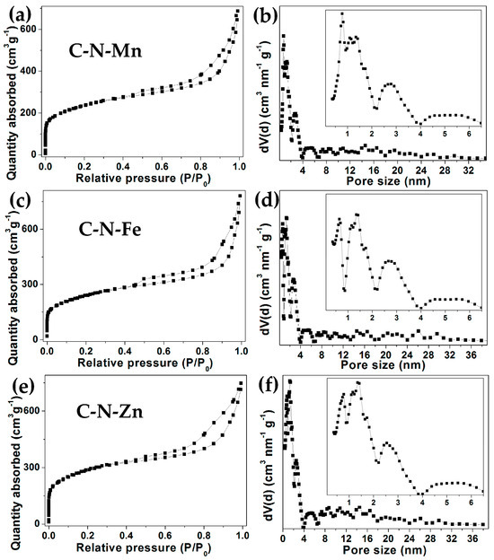
Figure 6.
Nitrogen adsorption–desorption isotherms and pore size distribution of the samples: C-N-Mn (a,b); C-N-Fe (c,d); C-N-Zn (e,f).
3. Materials and Methods
All the chemical reagents used were of analytical grade without further purification.
3.1. Synthesis of C-N-Mn
C-N-Mn was obtained from the precursor MnO@C-N, which was prepared according to our previous work with a minor change [25]. Typically, C10H12MnN2Na2O8 (EDTA-disodium manganese salt (3 g) and NaCl (3 g) were mixed together and ball-milled in a mortar with a rotation speed of 200 rpm for one night. Then, the mixture was pressed into several circular columns with a diameter of 15 mm (4~6 MPa for 20 s) and heated to 700 °C for 4 h at a heating rate of 5 °C min−1 under a N2 atmosphere. When cooling down to room temperature, the product was dissolved in hydrochloric acid (HCl, 1 M) and stirred for 4 h to remove MnO, NaCl, and other possible sodium salt, and the final sample was collected by vacuum filtration, washed with distilled water and ethanol sequentially, and then dried at 80 °C for 5 h, after which it was named C-N-Mn.
3.2. Synthesis of C-N-Fe
C-N-Fe was synthesized the same way as the C-N-Mn sample, except C10H12MnN2Na2O8 was replaced by C10H12FeN2NaO8 (ethylenediaminetetraacetic acid monosodium ferric salt).
3.3. Synthesis of C-N-Zn
C-N-Zn was synthesized the same way as the C-N-Mn sample, except C10H12MnN2Na2O8 was replaced by C10H12ZnN2Na2O8 (ethylenediaminetetraacetic acid disodium zinc salt).
3.4. Samples Characterization
X-ray diffraction (XRD diffractometer, D8 Advanced, Bruker Co., Berlin, Germany) and Raman spectroscopy (collected using a 532 nm laser, ThermoFisher DXR 2) were used to investigate the crystal structures of the samples. The morphology of the products was observed through scanning electron microscopy (SEM, Merlin Compact, Carl Zeiss AG, Jena, Germany) and transmission electron microscopy (TEM, Thermo Fischer, Talos F200x, Waltham, MA, USA). The elemental distribution of the samples was detected by energy-dispersive X-ray spectrometry (EDS) elemental mapping analysis (Merlin Compact, Carl Zeiss AG, Jena, Germany). X-ray photoelectron spectra (XPS) were acquired using an ESCALAB 250 instrument (Thermo Fischer, EACALAB 250, Waltham, MA, USA). Porosity analysis was tested by N2 adsorption/desorption measurements at 77 K with an Autosorb-IQ-C analyzer of Quantachrome (Belsorp Max, MicrotracBEL, Osaka, Japan).
4. Conclusions
This article used commercially available ethylenediaminetetraacetic acid metal salts as raw materials, followed by thermal decomposition and acid corrosion treatment under a nitrogen atmosphere, after which three types of nitrogen-doped amorphous carbon materials were obtained. These materials are all very thin carbon films with a large surface area containing pores and wrinkled structures. The reasons why we chose such substances as raw materials are as follows: 1. They are common and chemically stable reagents that are relatively inexpensive; 2. these compounds contain both carbon and nitrogen atoms, and they are carbon–nitrogen homologous, which is conducive to the nitrogen-doping process; 3. during the carbonization process, the doping process of nitrogen atoms is simultaneously realized, thereby simplifying the synthesis route. In addition, the obtained products have a large number of micropores and mesopores, as well as a large surface area. The carbon materials prepared by this method may have potential applications in fields such as energy storage and conversion, supercapacitors, and catalyst supports.
Supplementary Materials
The following supporting information can be downloaded at: https://www.mdpi.com/article/10.3390/inorganics13050148/s1, Figure S1: XRD of the MnO-C-N sample; Figure S2: XRD of the Fe/Fe3N/Fe4N-C-N sample; Figure S3: XRD of the ZnO-C-N sample; Figure S4: Elemental mapping and EDS spectrum of the MnO-C-N sample; Figure S5: Elemental mapping and EDS spectrum of the Fe/Fe3N/Fe4N-C-N sample; Figure S6: Elemental mapping and EDS spectrum of the ZnO-C-N sample; Figure S7: Repeat experiments using disodium manganese ethylenediaminetetraacetate; Figure S8: Disodium manganese ethylenediaminetetraacetate reagent; Table S1: Metal Activity Series; Table S2. The proportion of different types of nitrogen in the three carbon materials.
Author Contributions
D.W.: conceptualization, writing, funding acquisition. Z.S. and L.X.: methodology, data curation, investigation. All authors have read and agreed to the published version of the manuscript.
Funding
This research was funded by the Natural Science Foundation of Shandong Province (ZR2017QB017).
Data Availability Statement
The authors confirm that the data supporting the findings of this study are available within the article and its Supplementary Materials.
Conflicts of Interest
The authors declare no conflict of interest.
References
- Saju, S.K.; Chattopadhyay, S.; Xu, J.; Alhashim, S.; Pramanik, A.; Ajayan, P.M. Hard carbon anode for lithium-, sodium-, and potassium-ion batteries: Advancement and future perspective. Cell Rep. Phys. Sci. 2024, 5, 101851. [Google Scholar] [CrossRef]
- Cherian, S.K.; Kishore, K.R.; Reddy, S.; Sharma, C.S. Candle Soot-Embedded Electrospun Carbon Nanofibers as a Flexible and Free-Standing Sulfur Host for High-Performance Lithium-Sulfur Batteries. ACS Appl. Nano Mater. 2023, 6, 15574–15587. [Google Scholar] [CrossRef]
- Illa, M.P.; Pathak, A.D.; Sharma, C.S.; Khandelwal, M. Bacterial Cellulose-Polyaniline Composite Derived Hierarchical Nitrogen-Doped Porous Carbon Nanofibers as Anode for High-Rate Lithium-Ion Batteries. ACS Appl. Energy Mater. 2020, 3, 8676–8687. [Google Scholar] [CrossRef]
- Illa, M.P.; Khandelwal, M.; Sharma, C.S. Modulated Dehydration for Enhanced Anodic Performance of Bacterial Cellulose derived Carbon Nanofibers. ChemistrySelect 2019, 4, 6642–6650. [Google Scholar] [CrossRef]
- Cherian, S.K.; Nanaji, K.; Sarada, B.V.; Rao, T.N.; Sharma, C.S. Sulfur confinement into highly porous banana peduncle-derived carbon for high-rate performance lithium-sulfur battery. J. Energy Storage 2024, 89, 111803–111817. [Google Scholar] [CrossRef]
- Tian, L.; Zhi, Y.; Yu, Q.; Xu, Q.; Demir, M.; Colak, S.G.; Farghaly, A.A.; Wang, L.; Hu, X. Enhanced CO2 Adsorption Capacity in Highly Porous Carbon Materials Derived from Melamine-Formaldehyde Resin. Energy Fuels 2024, 38, 13186–13195. [Google Scholar] [CrossRef]
- Lu, T.; Bai, J.; Huang, J.; Yu, Q.; Demir, M.; Kilic, M.; Altay, B.N.; Wang, L.; Hu, X. Self-Activating Approach for Synthesis of 2,6-Naphthalene Disulfonate Acid Disodium Salt-Derived Porous Carbon and CO2 Capture Performance. Energy Fuels 2023, 37, 3886–3893. [Google Scholar] [CrossRef]
- Xie, L.; Li, Q.; Demir, M.; Yu, Q.; Hu, X.; Jiang, Z.; Wang, L. Lotus seed pot-derived nitrogen enriched porous carbon for CO2 capture application. Colloids Surf. A Physicochem. Eng. Asp. 2022, 655, 130226–130235. [Google Scholar] [CrossRef]
- Ma, C.; Lu, T.; Demir, M.; Yu, Q.; Hu, X.; Jiang, W.; Wang, L. Polyacrylonitrile-Derived N-Doped Nanoporous Carbon Fibers for CO2 Adsorption. ACS Appl. Nano Mater. 2022, 5, 13473–13481. [Google Scholar] [CrossRef]
- Liu, J.; Chen, C.; Wu, H.; Cheng, J. Kinetics and oxidation pathways of Fe3+-catalyzed carbon-assisted water electrolysis for hydrogen production. Int. J. Hydrog. Energy 2022, 47, 20432–20447. [Google Scholar] [CrossRef]
- Jin, Q.; Xiao, L.; He, W.; Cui, H.; Wang, C. Self-supported metal(Fe, Co, Ni)-embedded nitrogen-doping carbon nanorod framework as trifunctional electrode for flexible Zn-air batteries and switchable water electrolysis. Green Energy Environ. 2023, 8, 1644–1653. [Google Scholar] [CrossRef]
- Shen, Q.; Fu, C.; Wang, J.; Yao, W.; Wu, T.; Ding, S.; Xu, P. Exergy-cost-carbon nexus of power-to-X system from carbon dioxide/water co-electrolysis driven by solar full-spectrum energy. Energy Convers. Manag. 2024, 308, 118382. [Google Scholar] [CrossRef]
- Yue, Y.; Yue, X.; Tang, X.; Han, L.; Wang, J.; Wang, S.; Du, C. Synergistic Adsorption and Photocatalysis Study of TiO2 and Activated Carbon Composite. Heliyon 2024, 10, e30817. [Google Scholar] [CrossRef]
- Asencios, Y.J.O.; Lourenço, V.S.; Carvalho, W.A. Removal of phenol in seawater by heterogeneous photocatalysis using activated carbon materials modified with TiO2. Catal. Today 2022, 388, 247–258. [Google Scholar] [CrossRef]
- Yu, Z.; Li, F.; Xiang, Q. Carbon dots-based nanocomposites for heterogeneous photocatalysis. J. Mater. Sci. Technol. 2023, 175, 244–257. [Google Scholar] [CrossRef]
- Pavlenko, V.; Khosravi H, S.; Zoitowska, S.; Haruna, A.B.; Zahid, M.; Mansurov, Z.; Supiyeva, Z.; Galal, A.; Ozoemena, K.I.; Abbas, Q.; et al. A comprehensive review of template-assisted porous carbons: Modern preparation methods and advanced applications. Mater. Sci. Eng. R Rep. 2022, 149, 100682. [Google Scholar] [CrossRef]
- Huang, J.; Liu, C.; Jin, Y.; Chen, J. Hierarchical porous carbon synthesis by carbonized polymer dots-based sacrificial template for high-performance supercapacitors. Chem. Eng. J. 2023, 461, 141930. [Google Scholar] [CrossRef]
- Wang, C.; Yan, B.; Zheng, J.; Feng, L.; Chen, Z.; Zhang, Q.; Liao, T.; Chen, J.; Jiang, S.; Du, C.; et al. Recent progress in template-assisted synthesis of porous carbons for supercapacitors. Adv. Powder Mater. 2022, 1, 100018. [Google Scholar] [CrossRef]
- Chen, L.; Yuan, Y.; Zhang, D.; Lin, Z.; Lin, J.; Li, S.; Guo, S. Construction of 3D hierarchical honeycomb macro/meso/micro-porous carbon with soft and hard templates for high-performance sodium-ion batteries. Mater. Lett. 2023, 334, 133737. [Google Scholar] [CrossRef]
- Young, C.; Chen, H.-T. Supercapacitor application of a three-dimensional carbon sphere-intercalated porous carbon fabricated using a hard template and a biomass material. Diam. Relat. Mater. 2022, 130, 109528. [Google Scholar] [CrossRef]
- Guan, L.; Hu, H.; Teng, X.-L.; Zhu, Y.-F.; Zhang, Y.-L.; Chao, H.-X.; Yang, H.; Wang, X.-S.; Wu, M.-B. Templating synthesis of porous carbons for energy-related applications: A review. New Carbon Mater. 2022, 37, 25–45. [Google Scholar] [CrossRef]
- Zhang, W.; Cheng, R.-R.; Bi, H.-H.; Lu, Y.-H.; Ma, L.-B.; He, X.-J. A review of porous carbons produced by template methods for supercapacitor applications. New Carbon Mater. 2021, 36, 69–81. [Google Scholar] [CrossRef]
- Zhang, K.; Li, X.; Liang, J.; Zhu, Y.; Hu, L.; Cheng, Q.; Guo, C.; Lin, N.; Qian, Y. Nitrogen-doped porous interconnected double-shelled hollow carbon spheres with high capacity for lithium ion batteries and sodium ion batteries. Electrochim. Acta 2015, 155, 174–182. [Google Scholar] [CrossRef]
- Li, X.; Zhu, X.; Zhu, Y.; Yuan, Z.; Si, L.; Qian, Y. Porous nitrogen-doped carbon vegetable-sponges with enhanced lithium storage performance. Carbon 2014, 69, 515–524. [Google Scholar] [CrossRef]
- Wei, D.; Xu, L.; Jiao, R.; Zhong, Z.; Ji, X.; Zeng, S. One-pot thermal decomposition of commercial organometallic salt to Fe2O3@C-N and MnO@C-N for lithium storage. Dalton Trans. 2021, 50, 6867–6877. [Google Scholar] [CrossRef]
Disclaimer/Publisher’s Note: The statements, opinions and data contained in all publications are solely those of the individual author(s) and contributor(s) and not of MDPI and/or the editor(s). MDPI and/or the editor(s) disclaim responsibility for any injury to people or property resulting from any ideas, methods, instructions or products referred to in the content. |
© 2025 by the authors. Licensee MDPI, Basel, Switzerland. This article is an open access article distributed under the terms and conditions of the Creative Commons Attribution (CC BY) license (https://creativecommons.org/licenses/by/4.0/).