Abstract
The self-foaming method offers a promising approach for producing AlCuFe metallic foams without the need for external foaming agents. Although it is well established that both alloy composition and heat treatment play a fundamental role in pore formation, the specific influence of annealing time on the resulting microstructure and physical properties remains insufficiently explored. In the present study, the effects of annealing time on the microstructure, phase evolution, and magnetic properties of self-foaming Al58Cu27Fe15 alloys are investigated. Metallic foams were synthesized using the self-foaming method, heat-treating the samples at 850 °C for 6, 9, 15, and 24 h. X-ray diffraction (XRD), differential thermal analysis (DTA), and scanning electron microscopy (SEM) reveal that prolonged annealing increases porosity, reaching 64% and 61% after 15 and 24 h, respectively. The porosity formation mechanism was attributed to a peritectic reaction involving the liquid metastable τ phase and the solid λ and β phases. Magnetic measurements indicated complex behavior consistent with the Curie–Weiss law, influenced by phase composition and interactions between Coulomb forces, Hund’s rule exchange, and Fe 3d–Al s, p orbital hybridization.
1. Introduction
Metallic foams are a class of advanced materials that have garnered significant attention in recent years due to their remarkable combination of properties, such as low density, high strength-to-weight ratio, and excellent energy absorption capacity [1,2,3,4]. Consisting of a highly porous metal matrix with a foam-like structure, these materials can exhibit either closed pores (closed-cell foams) or open pores (open-cell foams), forming diverse structural networks [1,2,5]. Metallic foams typically exhibit porosity levels ranging from 50% to 95%, depending on the production method and desired structural properties [4,6]. This characteristic results in a material with significantly lower density than solid metal while having unique mechanical and physical properties [6]. Due to their low-density, high-energy absorption capacity and excellent thermal and acoustic properties, these materials find applications in diverse industries, including aerospace, biomedical, automotive, and construction, as lightweight structural components, impact-absorbing components, heat sinks, and acoustic damping materials [1,2,3,4,6,7].
Beyond their structural benefits, metallic foams are increasingly valued for their large surface area, enhanced catalytic activity, and ability to interact with electromagnetic radiation [8,9,10,11,12,13]. These features make them suitable for a wide range of functional applications, such as electrocatalysts, fuel cells, batteries, supercapacitors, and biomedical implants [3,7,14,15,16,17,18]. Furthermore, recent studies have highlighted the potential of metallic foams in electromagnetic and magnetic applications, including electromagnetic interference (EMI) shielding, magnetic scaffolds for biomedical imaging, and magnetically responsive systems [19,20,21,22].
Generally, metallic foams can be fabricated by bubbling gas through the molten metal, adding foaming agents such as metal oxides, hydrides, or carbonates, or using sacrificial agents like waxes or polymeric foams [3,23]. However, alternative routes that allow the manufacture of metallic foams without using external agents such as gases or sacrificial materials for pore formation are still being explored. In this sense, the self-foaming method is an innovative procedure to obtain AlCuFe metallic foams with porosity percentages ranging from 30% to 65% by volume [24,25]. The pore formation mechanism in this system is correlated to the presence of an icosahedral ι-phase formation by a peritectic reaction between a liquid phase and the solid phases β-AlFe(Cu) and λ–Al13Fe4 [24,25,26,27,28]. Due to the crystalline and quasicrystalline phases exhibiting significant composition and atomic volume differences, the pore formation has been reported as a consequence during the solidification process [29].
While diverse studies in the field have explored the synthesis of AlCuFe metallic foams across a wide range of stoichiometric compositions, providing detailed insights into the porosity formation mechanism, thermal, structural, and mechanical properties [24,25,26], the effects of time annealing on the microstructure, phase evolution, and magnetic properties have not yet been studied.
Although the magnetic behavior of dense AlCuFe crystalline and quasicrystalline phases has been extensively investigated, typically revealing diamagnetic, antiferromagnetic, or weak ferromagnetic responses influenced by structural order and defect concentration [30,31,32,33,34,35,36,37,38,39], the magnetic properties of their porous counterparts remain largely unexplored. In foamed systems, porosity inherently introduces a high density of structural defects. It alters the local electronic environment, which can significantly impact magnetic interactions and, consequently, the overall magnetic response.
Understanding how annealing time influences microstructure and phase stability is thus crucial for optimizing the self-foaming process and tailoring the resulting functional properties. In this sense, the present study investigates the effects of annealing time on the microstructure, phase evolution, and magnetic properties of self-foaming AlCuFe alloys, particularly emphasizing the Al58Cu27Fe15 composition.
The results indicate a direct correlation between annealing time and the simultaneous evolution of porosity, phase composition, and magnetic response. Notably, the study identifies the key role of the metastable τ liquid phase in facilitating the formation of the icosahedral quasicrystalline ι-phase. Furthermore, the study shows that the structural disorder induced by porosity enhances the development of localized magnetic moments on Fe atoms. This results in a complex magnetic behavior characterized by the coexistence of ferromagnetic, antiferromagnetic, and diamagnetic contributions.
2. Results and Discussion
2.1. Structural Characterization
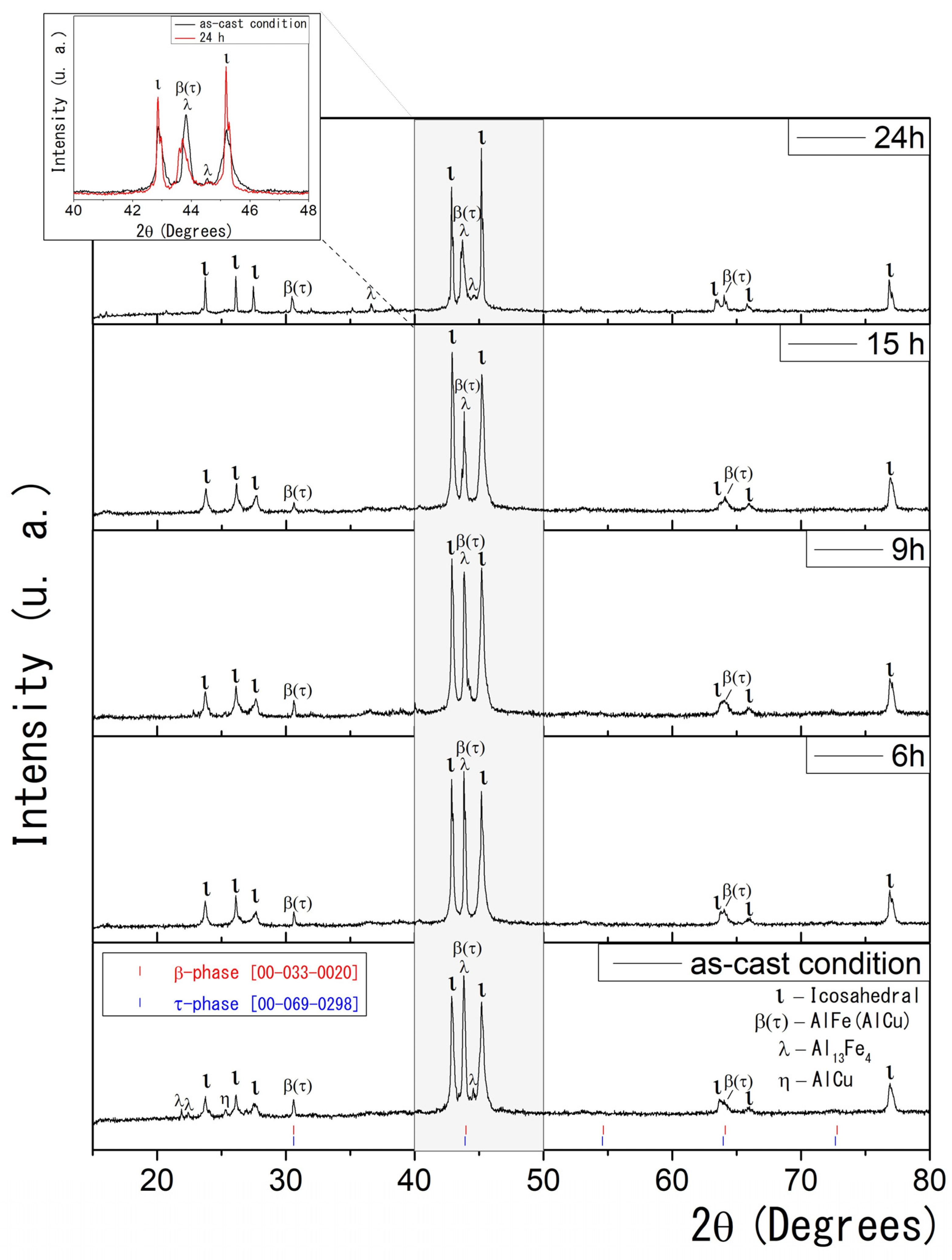
Figure 1 presents the XRD results for conventionally solidified Al58Cu27Fe15 alloys. The as-cast condition sample shows five crystalline phases: monoclinic λ–Al13Fe4 (λ) [40,41], icosahedral quasicrystalline ι-Al6Cu2Fe (ι), monoclinic η-AlCu (η) solid solution [42], and the CsCl type cubic β-AlFe(Cu) (β) and τ-AlCu(Fe) (τ) phases [24,25,26,27,43,44,45]. As previously reported in the literature, the XRD technique cannot reliably distinguish between the stable β and the metastable τ phases due to their similar CsCl-like cubic structures and nearly identical lattice parameters [24,27]. Therefore, the XRD data collectively label them as the β(τ) phase.
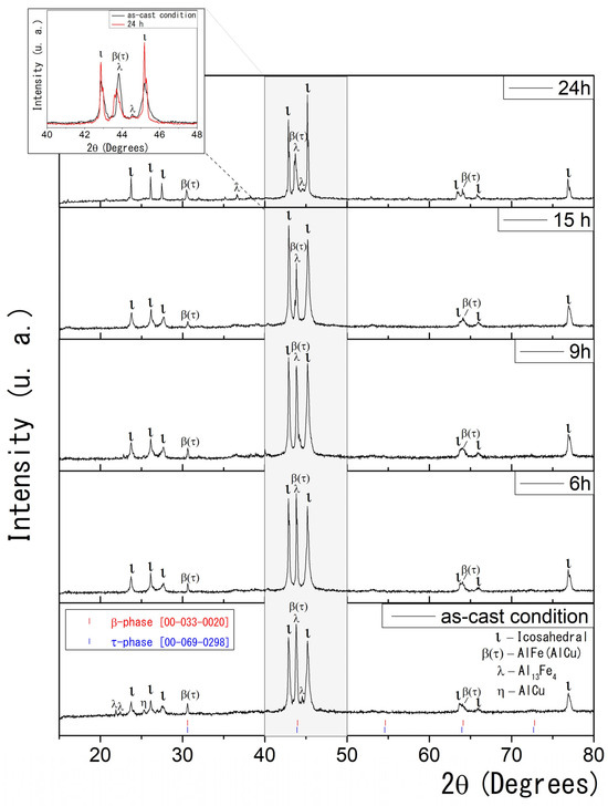
Figure 1.
(Color online) As-cast condition and heat-treated XRD data for Al58Cu27Fe15 alloys. Standard reference patterns (COD ID) are shown for β and τ phases, highlighting their structural similarity and overlapping diffraction peaks. The inset compares the XRD patterns for the as-cast condition and the sample heat-treated for 24 h.
The samples exhibit noticeable microstructural changes with progressive and prolonged heat treatment at 850 °C. After six hours of heat treatment, the XRD analysis revealed the presence of three distinct phases: ι-Al6Cu2Fe, β(τ), and λ-Al13Fe4. Notably, the η phase was not detected, although trace amounts below the detection limit cannot be excluded.
As the heat treatment time increases, the quasicrystalline ι phase in the samples becomes more prominent. This results from stabilizing the icosahedral phase at elevated temperatures over extended periods, promoting its formation. In the 2θ range between 30° and 50° (highlighted in grey), the intensity of the peaks corresponding to the β(τ) and λ phases progressively decreases, while the peaks associated with the ι phase become narrower and more intense. This suggests a phase transformation and improved crystallinity of the thermodynamically stable ι phase. The inset of Figure 1 compares the XRD patterns for the as-cast condition and the sample heat-treated for 24 h.
According to the literature, the formation of the icosahedral ι phase is driven by interactions between solid phases, such as λ or β, and a surrounding liquid phase through a peritectic reaction [24,25,26,27]. Gogebakan et al. further describe this phenomenon, reporting that the melting of the metastable τ phase in the presence of the β phase facilitates the development of the icosahedral ι phase [27]. Consistent with these observations, the present study identifies the interaction between the λ and β phases and the partially melted τ phase as a crucial factor in the emergence of the quasicrystalline ι phase. This transformation is evidenced by the gradual decrease in the XRD reflection intensities of the λ and β(τ) phases with increasing heat-treatment time, indicating their consumption during ι phase formation.
2.2. DSC Characterization
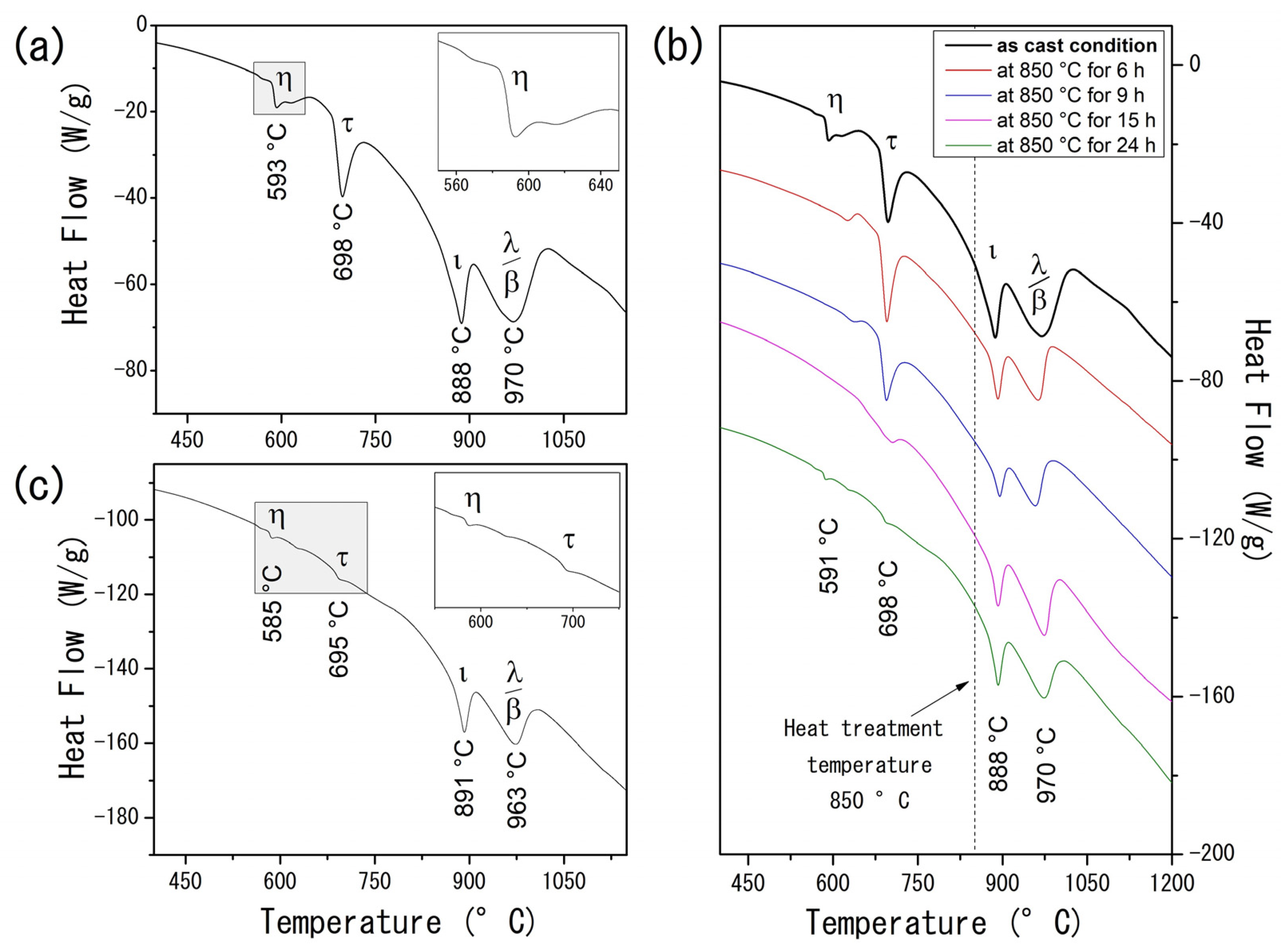
Calorimetric analysis on the AlCuFe alloys complements the XRD findings and provides further insights into the system’s thermal behavior. For the as-cast condition sample (Figure 2a), the DTA curve displays four prominent endothermic peaks at 593 °C, 698 °C, 888 °C, and 970 °C. These peaks correspond to the melting points of the η–AlCu, τ–AlCu(Fe), ι-Al6Cu2Fe, β–AlFe(Cu), and λ–Al13Fe4 phases, respectively [24,25,26]. Unlike the XRD results, which are limited in distinguishing between the stable β and the metastable τ phase due to their similar CsCl-type structures and lattice parameters, the DTA data differentiate these phases based on their distinct melting behaviors. Specifically, the metastable τ phase, characterized by a lower Fe content, melts at 698 °C, whereas the thermodynamically stable β phase melts at a higher temperature of 970 °C [27].

Figure 2.
(Color online) (a) DTA curve of the Al58Cu27Fe15 alloy in the as-cast condition. The inset shows a magnification of the η–AlCu transition region; (b) evolution of DTA curves of the heat-treated Al58Cu27Fe15 alloys; (c) DTA curve of the Al58Cu27Fe15 alloy heat-treated at 850 °C for 24 h. The inset magnifies the η–AlCu and τ–AlCu(Fe) transition region.
The evolution of heat flow as a function of annealing time for the AlCuFe system is presented in Figure 2b. As the heat treatment time increases, a gradual reduction in heat flow associated with the η and τ phases becomes evident. Notably, after 24 h of heat treatment (Figure 2c), the endothermic peaks at 585 °C and 695 °C are almost entirely suppressed, underscoring the substantial effect of prolonged heat treatments on phase stability and microstructural evolution in Al58Cu27Fe15 alloys.
2.3. Microstructural Characterization
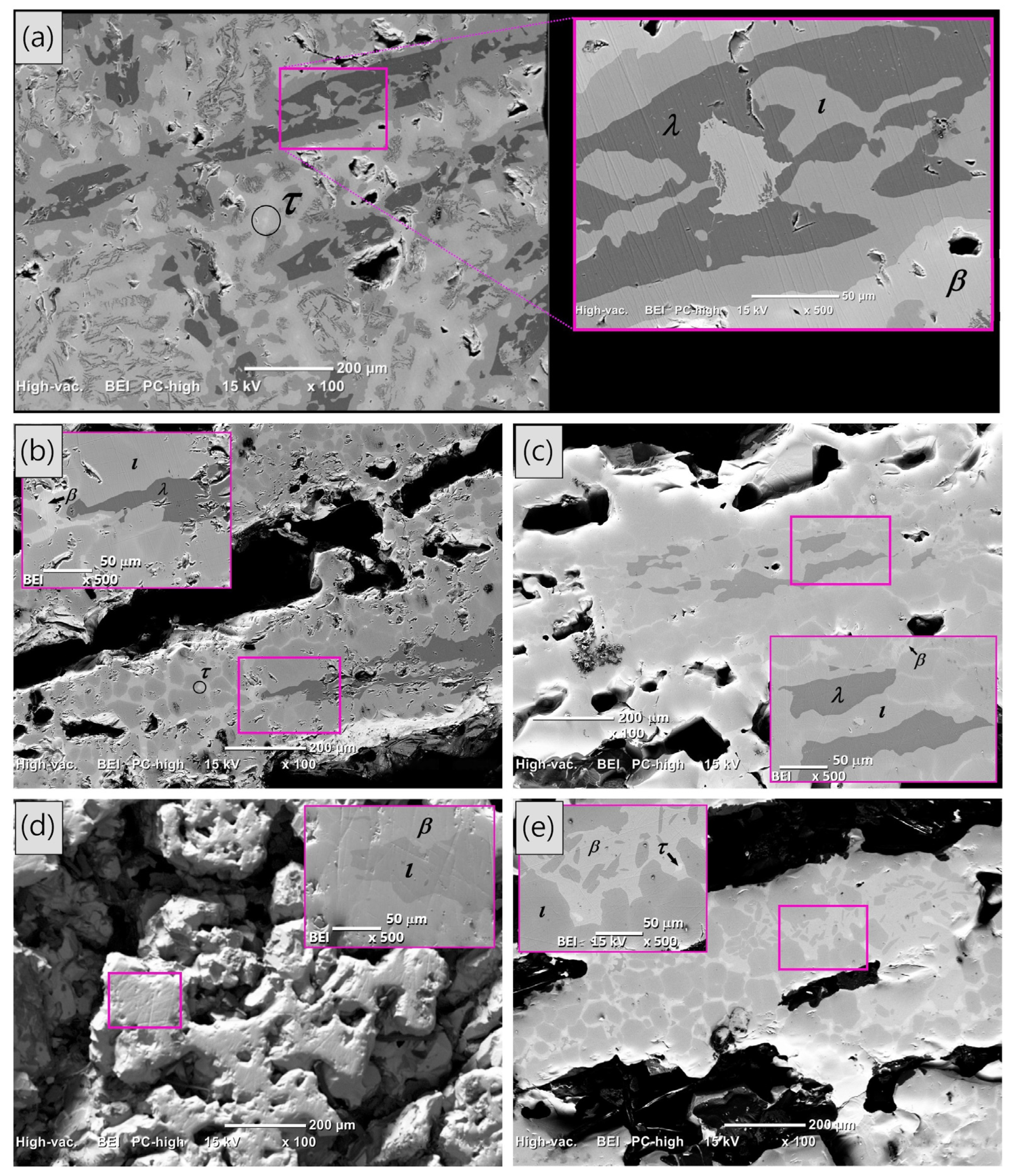
Back-scattered SEM images of the as-cast condition and heat-treated AlCuFe alloys are shown in Figure 3. In the as-cast condition sample (Figure 3a), the phase distribution exhibits a dendritic structure, with some black dendrites growing in parallel along different orientations. The enlarged image in Figure 3a highlights distinct contrast areas corresponding to the λ, ι, β, and τ phases, with chemical compositions (determined by EDS analysis) as follows: λ-Al72.85Cu5.16Fe21.99, ι-Al62.51Cu27.30Fe10.19, β-Al59.36Cu36.82Fe3.82, and τ-Al52.74Cu45.28Fe1.98. These measured compositions agree with the expected elemental ranges reported in the literature [26]. Furthermore, EDS analyses across all AlCuFe alloys investigated consistently yielded elemental compositions within the following ranges for the identified phases: λ-Al75-71Cu5-4Fe23-20, ι-Al66-60Cu29-22Fe12-10, β-Al60-58Cu38-35Fe4-2, and τ-Al54-50Cu48-44Fe3-2.
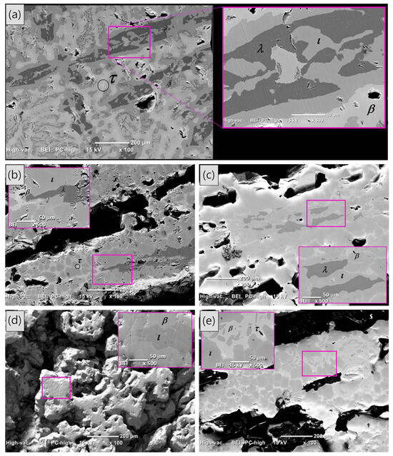
Figure 3.
(Color online) Back-scattered SEM images of the self-foaming Al58Cu27Fe15 alloys: (a) shows the as-cast condition sample, while (b–e) depict the heat-treatment samples at 850 °C for 6, 9, 15, and 24 h, respectively. The inset in each SEM image provides an enlarged view of the area marked in the main image, where the phases present in the alloy are indicated.
After resolidification at different heat treatments (Figure 3b–e), porosity develops, and the phase distribution changes, with the icosahedral ι and β phases predominantly dominating the resolidified samples in alignment with the previous XRD data presented in Figure 1. Small amounts of the λ and τ phases are also observed; however, as the heat treatment time increases, their presence tends to diminish due to the peritectic reaction between both phases.
Table 1 summarizes the respective volumetric porosity percentages (determined according to the procedure described in [25]), average pore sizes, and the corresponding densities for each AlCuFe alloy composition. The as-cast condition sample exhibits an experimental density of 4.45 g/cm3 and a volumetric porosity percentage of 7.8%. As the heat treatment time increases, the density decreases while the porosity percentage increases, showing a clear inverse relationship between these two properties. This trend suggests that prolonged heat treatment facilitates the development of pores within the metallic structure due to the formation of the quasicrystalline phase, which promotes porosity formation [25]. Samples subjected to 15 and 24 h of heat treatment exhibit the highest volumetric porosity percentages alongside correspondingly lower density values. Notably, these samples feature a porous, multilayered, sandwich-like structure, with apparent interconnectivity between pores, similar to that reported by D. Wei and co-workers [46]. Such an arrangement could be highly beneficial for applications that require increased surface exposure, such as catalysis or gas adsorption, since the channels between adjacent AlCuFe layers enhance the exposure of the facets to the surrounding environment, potentially increasing interaction efficiency with reactants [46]. A macroscopic view of the porosity distribution in the samples is provided in Figure S1 of the Supplementary Materials.

Table 1.
Experimental volumetric porosity percentage, average pore size, and density of Al58Cu27Fe15 self-foaming alloys.
On the other hand, as shown in Table 1, the average pore size follows a non-linear trend with respect to annealing time. After six hours of heat treatment, a significant increase in average pore size is observed (0.554 mm2), while in prolonged annealing (15 and 24 h), the average pore size decreases (0.183 mm2 and 0.228 mm2, respectively), suggesting pore fragmentation and redistribution, maybe due to enhanced stability of the ι-phase. Notably, the standard deviations for these conditions are higher, reflecting a broader and more heterogeneous pore size distribution.
SEM images, Figure S1 (Supplementary Materials), show a morphological evolution—from a dense, compact structure in the as-cast condition sample to large, irregular pores at 6 h, and finally to more uniform, rounded, and interconnected pores at 15 and 24 h. These microstructural changes result in a multilayered structure with enhanced surface connectivity.
2.4. Magnetic Properties
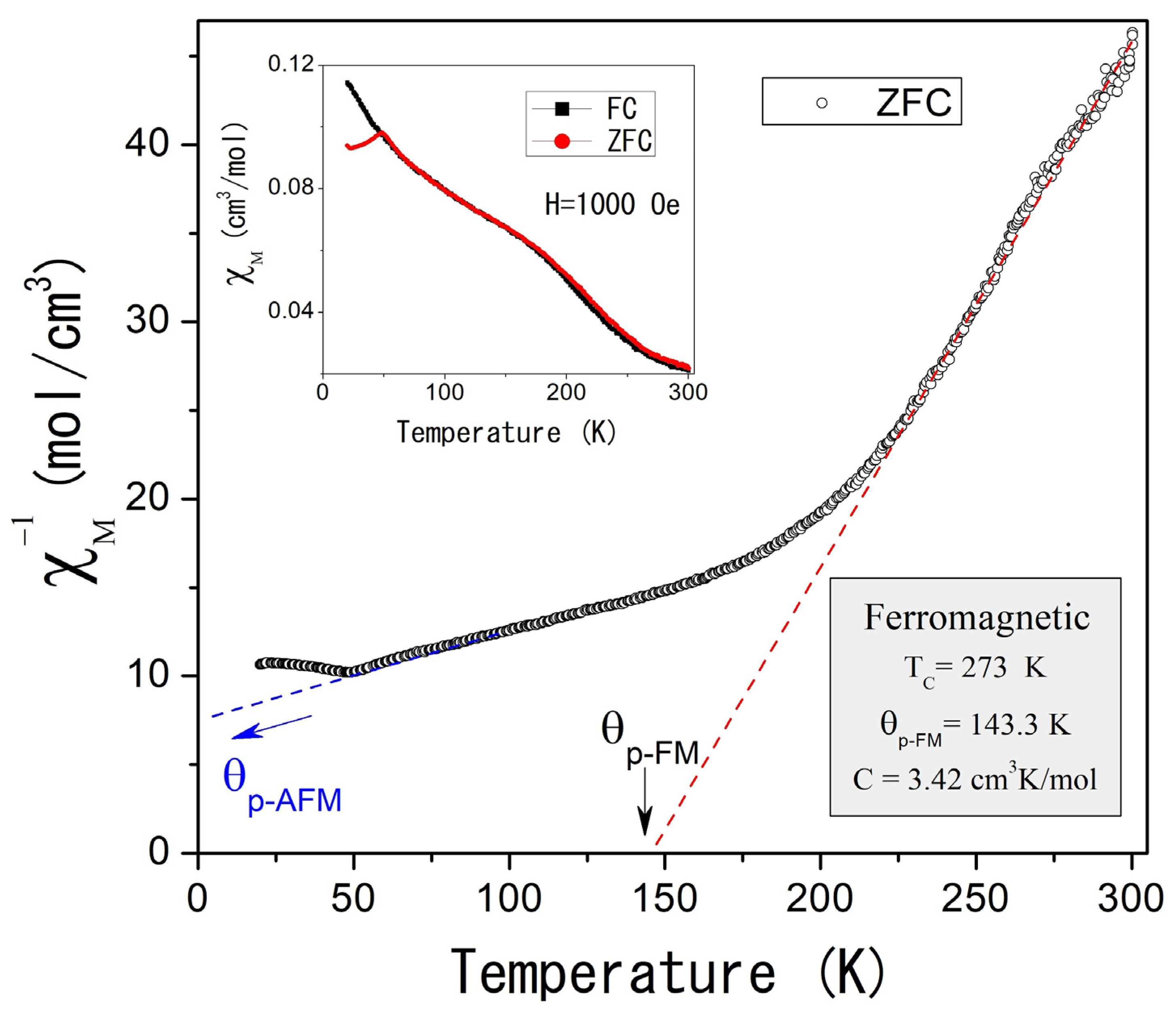
The magnetic properties of self-foaming AlCuFe alloys were investigated using powder samples under Zero Field Cooling (ZFC) and Field Cooling (FC) conditions. Figure 4 illustrates the temperature dependence of the inverse molar magnetic susceptibility, , measured at an applied magnetic field of 1000 Oe in ZFC mode for the as-cast condition sample. The inset of Figure 4 compares the χm(T) response in both ZFC and FC modes, revealing magnetic irreversibility at low temperatures. Below 300 K, the as-cast condition sample displays complex magnetic behavior that follows the Curie–Weiss law.
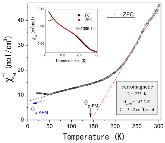
Figure 4.
(Color online) Inverse of the molar magnetic susceptibility as a function of the temperature for the Al58Cu27Fe15 as-cast condition alloy, measured at 1000 Oe and ZFC mode. The inset shows magnetic susceptibility as a function of temperature measured in ZFC and FC modes.
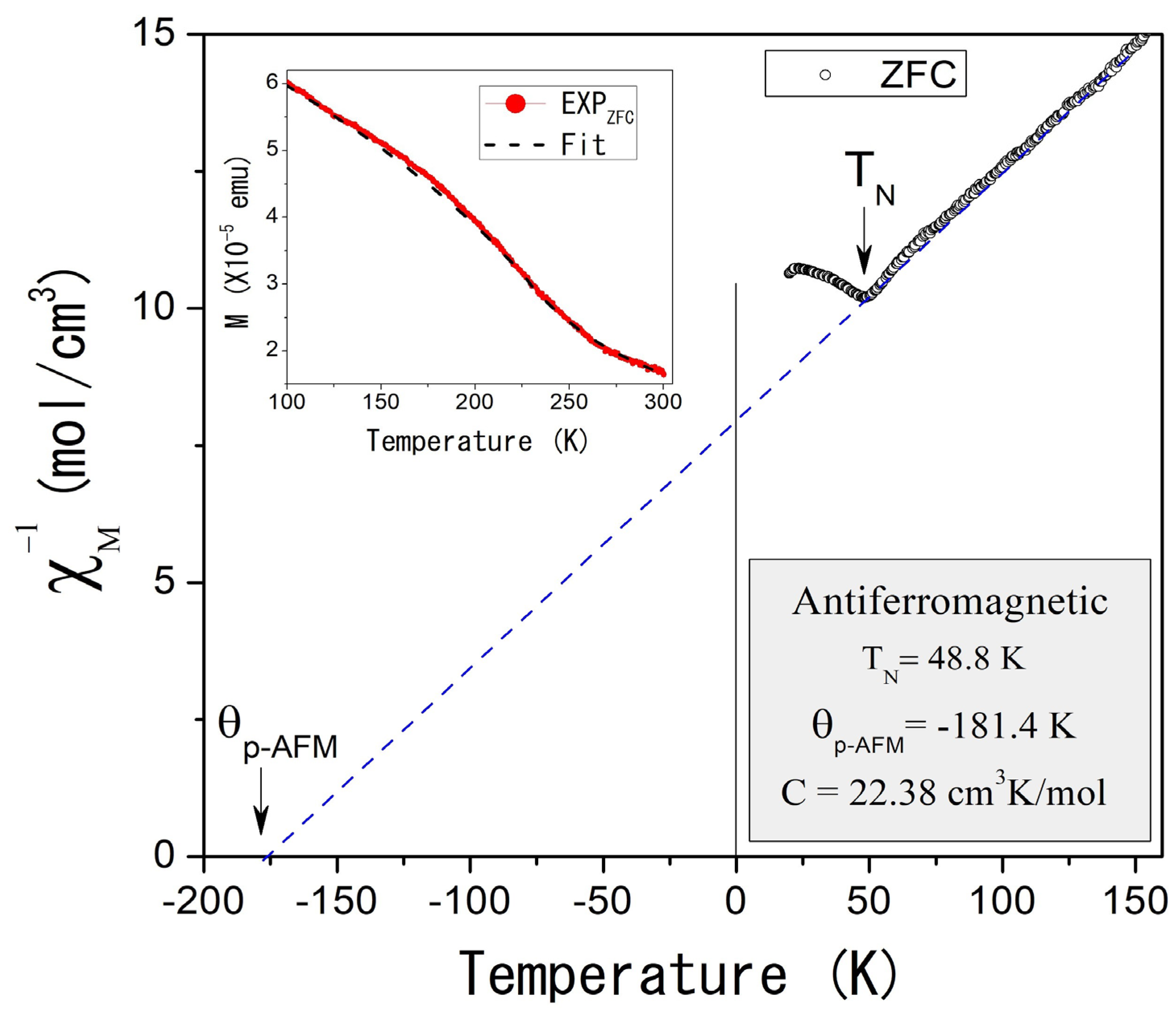
Two distinct magnetic contributions are observed: the first, at higher temperatures (TC = 273 K), indicates ferromagnetic ordering, while the second, at lower temperatures (TN = 48.8 K, Figure 5), suggests antiferromagnetic ordering. Curie–Weiss fitting of the experimental data (dotted straight lines, Figure 4 and Figure 5) reveals paramagnetic Curie temperatures p of 143.3 K and −181.4 K for the ferromagnetic and antiferromagnetic orderings, while the Curie constants were 3.42 cm3 K/mol and 22.38 cm3 K/mol, respectively. That implies magnetic moments of 5.23 µB and 13.03 µB.
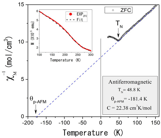
Figure 5.
(Color online) Inverse of the molar magnetic susceptibility as a function of the temperature in the region 20–150 K for the Al58Cu27Fe15 as-cast condition alloy, measured at 1000 Oe and ZFC mode. The inset shows the fitting of the experimental magnetization as a function of temperature for the AlCuFe as-cast condition sample. Fitting considers the paramagnetic contribution.
The magnetic properties of AlCuFe alloys are mainly attributed to an intricate interplay of structural and atomic factors intrinsic to their multiphase composition. Two competing mechanisms influence the magnetic behavior; on the one hand, Coulomb interactions and Hund’s rule exchange forces promote the local magnetic moment formation on Fe atoms; on the other, Fe 3d-Al s, p orbital hybridization strongly weakens exchange coupling, resulting in a non-magnetic state on Fe atoms [47,48,49,50,51,52].
The present study correlates the observed ferromagnetic and antiferromagnetic contributions in the self-foaming alloys with the presence of the quasicrystalline icosahedral ι phase and the β-AlCu(Fe) phase. Prior studies report the observation of soft ferromagnetism in the mechanically alloyed Al65Cu20Fe15 quasicrystalline phase, suggesting that the magnetic ordering arises from the compositional short-range order coupled with small relative changes in local symmetry [47]. These factors weaken the Fe 3d-Al s, p hybridization, facilitating the formation of localized magnetic moments on Fe atoms, which collectively establish ferromagnetic ordering by possible Fe clustering.
On the other hand, the antiferromagnetic contribution is correlated with the antiferromagnetic indirect exchange interaction (Ruderman–Kittel–Kasuya–Yosida interaction) between the localized magnetic moments on Fe induced by intrinsic structural defects in the β-AlCu(Fe) phase [48]. Antisite defects characterize the degree of order in the β(CsCl) phase; for the ordered state, Fe atoms are localized in the 3d-Me sublattice and have the maximum of Fe-Al bonds in the first coordination polyhedron. The Fe 3d-Al s, p hybridization strongly weakens the exchange coupling and results in the non-magnetic state of Fe in β-AlCu(Fe) [48,49,50,51,52]. Instead, for the FeAl3 localization, exchange coupling splits the spin-up and spin-down Fe 3d states, enhancing the iron magnetic moment. In addition, distortions of the coordination polyhedrons Al-Fe(Cu) and the increase in the interatomic Al-Fe distances can also lead to electron rearrangement from spin-down to spin-up Fe 3d-states and enhancement of magnetic moments on Fe atoms [52].
Additionally, the second-order paramagnetic-to-ferromagnetic phase transition in the AlCuFe as-cast sample was further analyzed. According to the scaling hypothesis, for a second-order phase transition, the spontaneous magnetization MS(T) below TC can be fitted by the expression [53]:
where the β parameter is a critical exponent that describes the behavior of the order parameter near the phase transition, while M0 represents the magnetization at 0 K. The inset of Figure 5 shows these results: the red curve represents the experimental data measured at 1000 Oe under ZFC conditions, while the black curve indicates the fitted data. The β parameter was determined to be 0.5, consistent with mean-field theory, which suggests that magnetic interactions are influenced by an average field generated by the neighboring atoms. This behavior, typical of systems with dominant long-range magnetic interactions, implies a relatively gradual transition to the ferromagnetic state.
Ms(T) = M0(1 − T/TC)β,
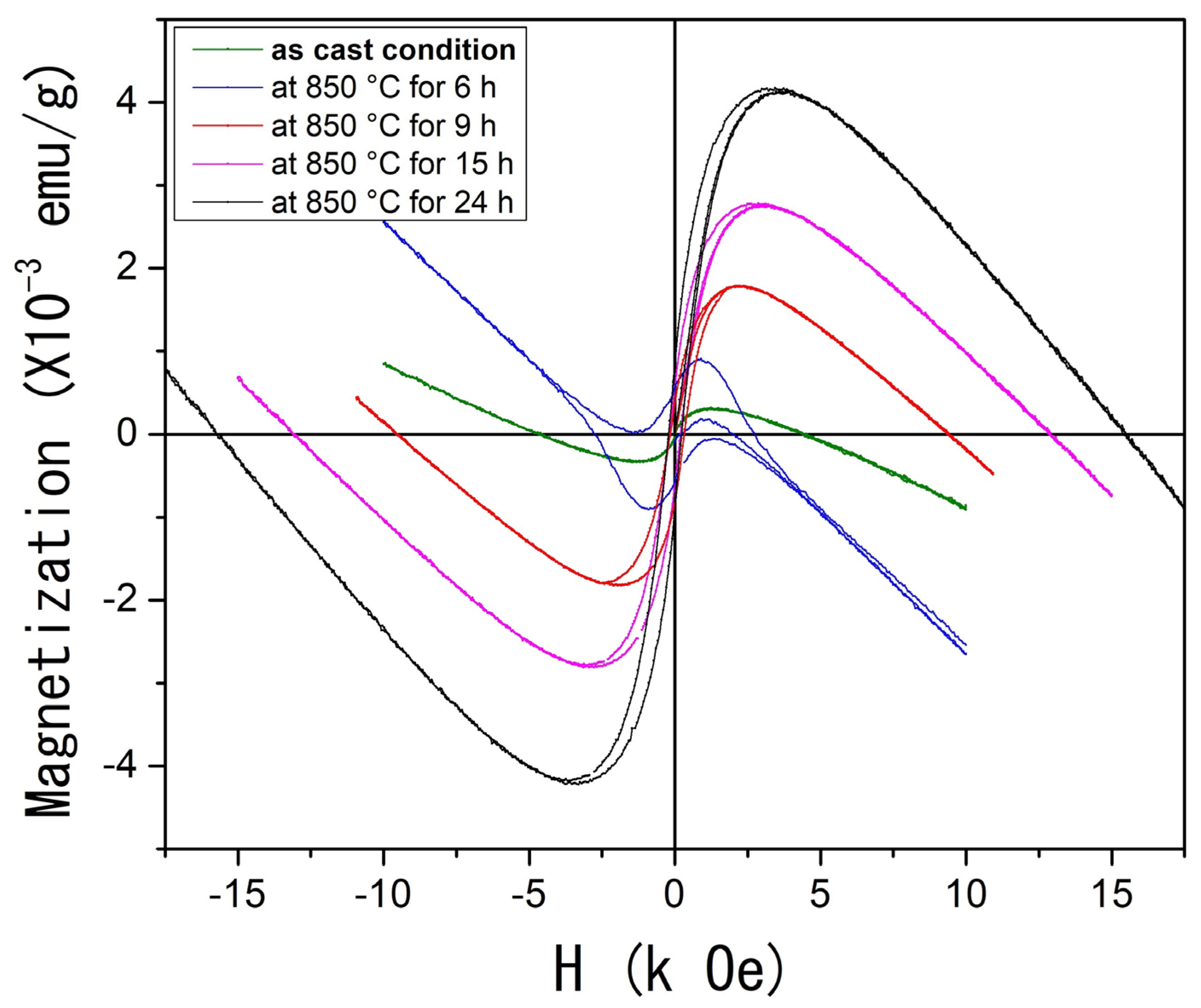
Finally, Figure 6 presents the M(H) feature measured at room temperature for both the as-cast condition and the heat-treated samples. The as-cast condition sample displays magnetic behavior that tends toward saturation around 1.3 kOe. Beyond this point, a diamagnetic contribution at higher applied magnetic fields leads the system to exhibit negative magnetization values with no coercive magnetic field.
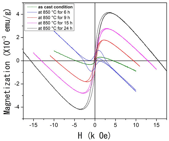
Figure 6.
(Color online) Magnetization as a function of applied magnetic field M(H) at room temperature of the Al58Cu27Fe15 system.
As the heat treatment time increases, a notable evolution in magnetization is observed. The AlCuFe system progressively reaches saturation at higher applied magnetic fields, exhibiting apparent soft ferromagnetic behavior characterized by increased saturation magnetization and lower coercivity. The coercive fields for the samples heat-treated for 9, 15, and 24 h were estimated at 162, 180, and 215 Oe, respectively. In contrast, the coercive field for the sample treated for 6 h could not be determined due to the strong diamagnetic contribution. It must be remembered that this diamagnetic effect is attributed to the Fe 3d-Al s, p hybridization, which strongly weakens the exchange coupling and results in the non-magnetic state of Fe atoms [48].
Prolonged heat treatments likely promote an increase in the concentration of Fe ions with localized magnetic moments, resulting from the breaking of strong Al–Fe covalent interactions induced by structural defects and porosity development. Consequently, the observed progressive enhancement in saturation magnetization with increasing annealing time can be attributed not only to phase transformations and the higher volume fraction of the ι-phase but also to the increased structural disorder and porosity, which facilitate the formation of Fe atoms with localized magnetic moments.
Understanding how controlled annealing treatments influence the microstructure, porosity, and magnetic properties of self-foaming AlCuFe alloys is crucial, as these materials could be used in electromagnetic interference shielding, gas absorption systems, catalytic supports, and hydrogen generation technologies.
3. Materials and Methods
Metallic foams with a nominal composition of Al58Cu27Fe15 were synthesized in situ via the self-foaming method [24,25,26]. This specific composition was selected because it lies in a strategic location within the Al–Cu–Fe ternary phase diagram, where the ι-icosahedral, λ-Al13Fe4, β-AlFe(Cu), and liquid phases simultaneously coexist at around 800 °C [54,55]. Analytical-grade elements—Al (99.9%), Cu (99.5%), and Fe (99.9%)—were melted in a magnetic induction furnace under an argon atmosphere to prevent oxidation. The molten alloy was gradually solidified at room temperature within the furnace at an average cooling rate of 0.12 °C/s. The resulting ingot was then cut into several rectangular prism-shaped samples and subjected to heat treatments at 850 °C for 6, 9, 15, and 24 h in an electric resistance furnace under an argon atmosphere.
Phase identification and structural analysis were achieved by X-ray powder diffractometry (XRD) using a Bruker D8 Advance X-ray Powder Diffraction System (Billerica, Massachusetts, USA) with Cu Kα radiation (λ = 1.5405 ). Phase identification was performed using Crystal Impact Match 3 software alongside the PDF-3 database (3.2.0 version). Differential Thermal Analysis (DTA) was carried out on a TA Instruments (New Castle, Delaware, USA) SDT Q-600 Calorimeter. Microstructural characterization was conducted using a FEG JEOL JSM-7600F (Tokyo, Japan) scanning electron microscope (SEM) operating at 15 kV, equipped with an Oxford INCA (Abingdon, UK) X-Act energy-dispersive X-ray analyzer (EDX). The experimental volume and density of the samples were measured using a Quantachrome Ultra PYC 1200e gas pycnometer (Boynton Beach, FL, USA). Porosity was quantified through SEM images, and several slices of highly porous ingots were analyzed using ImageJ software (1.51k version). Magnetic properties were evaluated using a Physical Properties Measurement System (PPMS, Quantum Design Dynacool, San Diego, CA, USA), studying the magnetic response as a function of temperature and applied magnetic field.
4. Conclusions
The present study investigated the impact of annealing time on the microstructure, phase evolution, and magnetic properties of self-foaming Al58Cu27Fe15 alloys. Key findings indicate that prolonged heat treatment at 850 °C promotes porosity formation through a peritectic reaction between the liquid metastable τ phase and the solid λ and β phases, which leads to the formation of the thermodynamically stable icosahedral ι phase. Samples heat-treated for 15 and 24 h exhibited the highest volumetric porosity percentages, reaching 64% and 61%, respectively.
Magnetic studies reveal complex magnetic behavior in the AlCuFe self-foaming alloys, driven by a combination of ferromagnetic, antiferromagnetic, and diamagnetic contributions. At higher temperatures (TC = 273 K), ferromagnetic ordering is associated with the quasicrystalline icosahedral ι phase, while antiferromagnetic ordering observed at lower temperatures (TN = 48.8 K) is attributed to the β-AlCu(Fe) phase. Two competing mechanisms influence this magnetic behavior: Coulomb interactions and Hund’s rule exchange forces favor the formation of local magnetic moments on Fe atoms, while Fe 3d–Al s, p orbital hybridization strongly weakens the exchange coupling, resulting in a non-magnetic state on Fe atoms. The phase composition and the interplay and balance between the Coulomb and Hund’s rule forces and the electron coupling are crucial for understanding the magnetic behavior of the AlCuFe systems.
Supplementary Materials
The following supporting information can be downloaded at https://www.mdpi.com/article/10.3390/inorganics13050149/s1, Figure S1: AlCuFe foams.
Author Contributions
Conceptualization, R.L. and I.A.F.; methodology, R.L. and J.M.H.; validation, I.A.F. and G.G.; formal analysis, R.L., J.M.H., I.A.L. and I.A.F.; investigation, R.L. and J.M.H.; resources, I.A.F.; data curation, R.L.; writing—original draft preparation, R.L., J.M.H., C.D., G.G. and I.A.F.; writing—review and editing, R.L., C.D., G.G. and I.A.F.; visualization, R.L. and I.A.F.; supervision, R.L., I.A.L., G.G. and I.A.F.; project administration, I.A.F.; funding acquisition, I.A.F. All authors have read and agreed to the published version of the manuscript.
Funding
This research was funded by the UNAM Postdoctoral Program (POSDOC) and DGAPA-PAPIIT UNAM, grant number IN103225.
Data Availability Statement
Data underlying the results presented in this paper are not publicly available but may be obtained from the authors upon reasonable request.
Acknowledgments
This work was supported by the UNAM Postdoctoral Program (POSDOC). Rodolfo López gratefully acknowledges POSDOC for the scholarship funding his postdoctoral stay. Carlos Damián is thankful for the postdoctoral scholarship granted by SECIHTI. The authors acknowledge the technical support provided by A. Morales in XRD acquisition data, Agustín Conde for conducting magnetic measurements, Carlos Flores for SEM and EDS characterization, and Ana Bobadilla and Karla Reyes for their invaluable technical support in XRD and SDT analyses. Carlos Ramos, Adrián Tejeda, Eliezer Hernández, Lourdes Bazán, Maricela Zapata, and Francisca García are also acknowledged for their technical support, “Por mi raza hablará el espíritu”.
Conflicts of Interest
The authors declare no conflicts of interest.
References
- Rajak, D.K.; Gupta, M. An Insight into Metal-Based Foams; Springer: Singapore, 2020. [Google Scholar]
- Hassan, A.; Alnaser, I.A. A Review of Different Manufacturing Methods of Metallic Foams. ACS Omega 2024, 9, 6280–6295. [Google Scholar] [CrossRef] [PubMed]
- Banhart, J. Manufacture, Characterisation and Application of Cellular Metals and Metal Foams. Prog. Mater. Sci. 2001, 46, 559–632. [Google Scholar] [CrossRef]
- Gibson, L.J. Cellular Solids. MRS Bull. 2003, 28, 270–274. [Google Scholar] [CrossRef]
- Oshida, Y. Bioscience and Bioengineering of Titanium Materials; Elsevier: Amsterdam, The Netherlands, 2010. [Google Scholar]
- Parveez, B.; Jamal, N.A.; Anuar, H.; Ahmad, Y.; Aabid, A.; Baig, M. Microstructure and Mechanical Properties of Metal Foams Fabricated via Melt Foaming and Powder Metallurgy Technique: A Review. Materials 2022, 15, 5302. [Google Scholar] [CrossRef] [PubMed]
- Ashby, M. Metal Foams: A Design Guide; Butterworth-Heinemann: Oxford, UK, 2000. [Google Scholar]
- Behymer, N.; Morsi, K. Closed-Cell Metallic Foams Produced via Powder Metallurgy. Metals 2023, 13, 959. [Google Scholar] [CrossRef]
- Ho, P.H.; Jabłonska, M.; Palkovits, R.; Rodríguez-Castellon, E.; Ospitali, F.; Fornasari, G.; Vaccari, A.; Benito, P. N2O Catalytic Decomposition on Electrodeposited Rh-Based Open-Cell Metallic Foams. Chem. Eng. J. 2020, 379, 122259. [Google Scholar] [CrossRef]
- Allioux, F.-M.; Merhebi, S.; Ghasemian, M.B.; Tang, J.; Merenda, A.; Abbasi, R.; Mayyas, M.; Daeneke, T.; O’Mullane, A.P.; Daiyan, R.; et al. Bi-Sn Catalytic Foam Governed by Nanometallurgy of Liquid Metals. Nano Lett. 2020, 20, 4403–4409. [Google Scholar] [CrossRef]
- Patil, K.N.; Prasad, D.; Manoorkar, V.K.; Nabgan, W.; Nagaraja, B.M.; Jadhav, A.H. Engineered Nano-Foam of Tri-Metallic (FeCuCo) Oxide Catalyst for Enhanced Hydrogen Generation via NaBH4 Hydrolysis. Chemosphere 2021, 281, 130988. [Google Scholar] [CrossRef]
- Gao, H.; Wang, C.; Yang, Z.; Zhang, Y. 3D Porous Nickel Metal Foam/Polyaniline Heterostructure with Excellent Electromagnetic Interference Shielding Capability and Superior Absorption Based on Pre-Constructed Macroscopic Conductive Framework. Compos. Sci. Technol. 2021, 213, 108896. [Google Scholar] [CrossRef]
- Liu, J.; Zhang, H.-B.; Sun, R.; Liu, Y.; Liu, Z.; Zhou, A.; Yu, Z.-Z. Hydrophobic, Flexible, and Lightweight MXene Foams for High-Performance Electromagnetic-Interference Shielding. Adv. Mater. 2017, 29, 1702367. [Google Scholar] [CrossRef]
- Liu, S.; Jiang, Y.; Yang, M.; Zhang, M.; Guo, Q.; Shen, W.; He, R.; Li, M. Highly Conductive and Metallic Cobalt-Nickel Selenide Nanorods Supported on Ni Foam as an Efficient Electrocatalyst for Alkaline Water Splitting. Nanoscale 2019, 11, 7959–7966. [Google Scholar] [CrossRef]
- Wu, Q.; Qin, M.; Yan, H.; Zhong, W.; Zhang, W.; Liu, M.; Cheng, S.; Xie, J. Facile Replacement Reaction Enables Nano-Ag-Decorated Three-Dimensional Cu Foam as High-Rate Lithium Metal Anode. ACS Appl. Mater. Interfaces 2022, 14, 42030–42037. [Google Scholar] [CrossRef]
- Deng, X.; Li, J.; Zhu, S.; He, F.; He, C.; Liu, E.; Shi, C.; Li, Q.; Zhao, N. Metal-Organic Frameworks-Derived Honeycomb-Like Co3O4/Three-Dimensional Graphene Networks/Ni Foam Hybrid as a Binder-Free Electrode for Supercapacitors. J. Alloys Compd. 2017, 693, 16–24. [Google Scholar] [CrossRef]
- Lyu, L.; Kang, J.; Seong, K.-d.; Kim, C.W.; Lim, J.; Piao, Y. ZnNiCo Hydroxide/Graphene-Carbon Nanotube Hydrogel on Surface-Modified Ni Foam as a Battery-Type Electrode for Hybrid Supercapacitors. J. Alloys Compd. 2021, 872, 159610. [Google Scholar] [CrossRef]
- Tong, X.; Shi, Z.; Xu, L.; Lin, J.; Zhang, D.; Wang, K.; Li, Y.; Wen, C. Degradation Behavior, Cytotoxicity, Hemolysis, and Antibacterial Properties of Electro-Deposited ZnCu Metal Foams as Potential Biodegradable Bone Implants. Acta Biomater. 2020, 102, 481–492. [Google Scholar] [CrossRef]
- Xu, Z.; Hao, H. Electromagnetic Interference Shielding Effectiveness of Aluminum Foams with Different Porosity. J. Alloys Compd. 2014, 617, 207–213. [Google Scholar] [CrossRef]
- Li, X.; Wang, K.; Li, Y.; Wang, Z.; Zhao, Y.; Zhu, J. Mechanical and Magnetic Properties of Porous Ni50Mn28Ga22 Shape Memory Alloy. Metals 2024, 14, 291. [Google Scholar] [CrossRef]
- Onishi, H.; Hyun, S.K.; Nakajima, H.; Mitani, S.; Takanashi, K.; Yakushiji, K. Magnetization Process of Lotus-Type Porous Metals. J. Appl. Phys. 2008, 103, 093539. [Google Scholar] [CrossRef]
- Hong, G.; Liu, J.; Cobos, S.F.; Khazaee, T.; Drangova, M.; Holdsworth, D.W. Effective Magnetic Susceptibility of 3D-Printed Porous Metal Scaffolds. Magn. Reson. Med. 2022, 87, 2947–2956. [Google Scholar] [CrossRef]
- Lefebvre, L.-P.; Banhart, J.; Dunand, D.C. Porous Metals and Metallic Foams: Current Status and Recent Developments. Adv. Eng. Mater. 2008, 10, 775–787. [Google Scholar] [CrossRef]
- Suarez, M.; Figueroa, I.; González, G.; Lara-Rodríguez, G.; Novelo-Peralta, O.; Alfonso, I.; Calvo, I. Production of Al-Cu-Fe Metallic Foams without Foaming Agents or Space Holders. J. Alloys Compd. 2014, 585, 318–324. [Google Scholar] [CrossRef]
- Hernández, J.; Figueroa, I.; González, G.; Salas, A.; Mendoza, L.; Alfonso, I.; Lara-Rodríguez, G. In-Situ Porosity Formation of Self-Foaming Al-Fe-Cu Alloys. Appl. Phys. A 2022, 128, 319. [Google Scholar] [CrossRef]
- Suárez, M.; Delgado-Pamanes, M.; Chávez-Alcalá, J.; Cruz-Ramírez, A.; Guadarrama, I.; Figueroa, I. Microstructural and Mechanical Characterization of Quasicrystalline Al-Cu-Fe Foams. Mater. Today Commun. 2022, 30, 103043. [Google Scholar] [CrossRef]
- Gögebakan, M.; Avar, B.; Uzun, O. Quasicrystalline Phase Formation in the Conventionally Solidified Al–Cu–Fe System. Mater. Sci. 2009, 27, 555–562. [Google Scholar]
- Babilas, R.; Bajorek, A.; Spilka, M.; Radoń, A.; Łoński, W. Structure and Corrosion Resistance of Al–Cu–Fe Alloys. Prog. Nat. Sci. Mater. Int. 2020, 30, 393–401. [Google Scholar] [CrossRef]
- Dubois, J.-M. New Prospects from Potential Applications of Quasicrystalline Materials. Mater. Sci. Eng. A 2000, 294, 4–9. [Google Scholar] [CrossRef]
- Quispe, M.P.; Landauro, C.V.; Vergara, M.Z.P.; Quispe-Marcatoma, J.; Rojas-Ayala, C.; Peña-Rodríguez, V.A.; Baggio-Saitovitch, E. Influence of High Energy Milling on the Microstructure and Magnetic Properties of the Al–Cu–Fe Phases: The Case of the i-Al64Cu23Fe13 Quasicrystalline and the ω-Al70Cu20Fe10 Crystalline Phases. RSC Adv. 2016, 6, 5367–5376. [Google Scholar] [CrossRef]
- Mendoza-Zélis, L.; Meyer, M.; Sánchez, F.H. Structural and Magnetic Properties of Mechanically Alloyed AlCuFe Intermetallics. Phys. Status Solidi C 2005, 2, 3581–3584. [Google Scholar] [CrossRef]
- Müller, F.; Rosenberg, M.; Liu, W.; Köster, U. Mössbauer Measurements and Susceptibility Measurements on Crystalline and Icosahedral AlCuFe Alloys. Mater. Sci. Eng. A 1991, 134, 900–903. [Google Scholar] [CrossRef]
- Zahoor, A.; Shahid, R.N.; Tariq, N.U.H.; Wahab, H.; Anwar, S.; Rafiq, M.A.; Hasan, B.A. Effect on Electrical and Magnetic Behavior of Al–Cu–Fe Quasicrystals during Surface Leaching. Appl. Phys. A 2021, 127, 551. [Google Scholar] [CrossRef]
- Nikonov, A.A.; Semenovskiĭ, P.V.; Teplov, A.A.; Shaĭtura, D.S. Magnetic Susceptibility of Quasicrystalline Al65Cu22Fe13 Powders. Crystallogr. Rep. 2007, 52, 980–983. [Google Scholar] [CrossRef]
- Semenovskiĭ, P.V.; Nikonov, A.A.; Teplov, A.A.; Ol’shanskiĭ, E.D.; Bryazkalo, A.M. Magnetic Properties of Quasicrystalline Al65Cu22Fe13 Powders Synthesized by Solid-Phase Diffusion. Crystallogr. Rep. 2010, 55, 833–836. [Google Scholar] [CrossRef]
- Dolinšek, J.; Vrtnik, S.; Klanjšek, M.; Jagličić, Z.; Smontara, A.; Smiljanić, I.; Landauro, C.V. Intrinsic Electrical, Magnetic, and Thermal Properties of Single-Crystalline Al64Cu23Fe13 Icosahedral Quasicrystal: Experiment and Modeling. Phys. Rev. B 2007, 76, 054201. [Google Scholar] [CrossRef]
- Meyer, M.; Sánchez, F.; Mendoza-Zélis, L. Magnetism and Disorder in BCC AlCuFe Intermetallics. Phys. B Condens. Matter 2007, 389, 163–167. [Google Scholar] [CrossRef]
- Nguyen, H.V.; Do, N.B.; Nguyen, T.H.O.; Nguyen, C.S.; Trinh, V.T.; Le, H.T.; Jorge Junior, A.M. Synthesis and Magnetic Properties of Al–Cu–Fe Quasicrystals Prepared by Mechanical Alloying and Heat Treatment. J. Mater. Res. 2023, 38, 644–653. [Google Scholar] [CrossRef]
- Lee, K.M.; Lee, J.H.; Kim, J.S.; Lee, J.W. Effect of Composition and Heat Treatment on the Magnetization Process of Al–Cu–Fe-Based Quasicrystalline Alloys. Mater. Chem. Phys. 2010, 123, 98–103. [Google Scholar]
- Grin, J.; Burkhardt, U.; Ellner, M.; Peters, K. Refinement of the Fe4Al13 Structure and Its Relationship to the Quasihomological Homeotypical Structures. Z. Kristallogr. Cryst. Mater. 1994, 209, 479–487. [Google Scholar] [CrossRef]
- Albedah, M.A.; Nejadsattari, F.; Stadnik, Z.M.; Przewoźnik, J. 57Fe Mössbauer Spectroscopy and Magnetic Study of Al13Fe4. J. Alloys Compd. 2015, 619, 839–845. [Google Scholar] [CrossRef]
- Wang, K.-K. The Orientation Relationships and Interfaces of θ-Al2Cu/Cu and γ2-Al4Cu9/Cu and the Formation Sequence of θ-Al2Cu and γ2-Al4Cu9 at the Cu/Al Interface. Thin Solid Film. 2021, 717, 138436. [Google Scholar] [CrossRef]
- Grushko, B.; Wittenberg, R.; Holland-Moritz, D. Solidification of Al–Cu–Fe Alloys Forming Icosahedral Phase. J. Mater. Res. 1996, 11, 2177–2185. [Google Scholar] [CrossRef]
- Gögebakan, M.; Avar, B.; Tarakçı, M. Microstructures and Mechanical Properties of Conventionally Solidified Al63Cu25Fe12 Alloy. J. Alloys Compd. 2011, 509, 316–319. [Google Scholar] [CrossRef]
- Gayle, F. Phase Equilibria at 550 °C in the Al-Cu-Fe System: 50 to 70 at.% Al, 0 to 9 at.% Fe. J. Phase Equilib. 1992, 13, 619–622. [Google Scholar] [CrossRef]
- Wei, D.; He, Z. Multilayered Sandwich-Like Architecture Containing Large-Scale Faceted Al-Cu-Fe Quasicrystal Grains. Mater. Charact. 2016, 111, 154–161. [Google Scholar] [CrossRef]
- Roy, M. Formation and Magnetic Properties of Mechanically Alloyed Al65Cu20Fe15 Quasicrystal. J. Magn. Magn. Mater. 2006, 302, 52–55. [Google Scholar] [CrossRef]
- Shalaeva, E.V.; Prekul, A.F.; Shchegolikhina, N.I.; Medvedeva, N.I. Curie Temperature and Density of States at the Fermi Level for Al-Cu-Fe Phases: β-Solid State Solution Approximants Icosahedral Quasicrystals. Acta Phys. Pol. A 2014, 126, 572–576. [Google Scholar] [CrossRef]
- Bogner, J.; Steiner, W.; Reissner, M.; Mohn, P.; Blaha, P.; Schwarz, K.; Krachler, R.; Ipser, H.; Sepiol, B. Magnetic Order and Defect Structure of FexAl1−x Alloys around x = 0.5: An Experimental and Theoretical Study. Phys. Rev. B 1998, 58, 14922. [Google Scholar] [CrossRef]
- Kulikov, N.I.; Postnikov, A.V.; Borstel, G.; Braun, J. Onset of Magnetism in B2 Transition-Metal Aluminides. Phys. Rev. B 1999, 59, 6824–6832. [Google Scholar] [CrossRef]
- Das, G.P.; Rao, B.K.; Jena, P.; Deevi, S.C. Electronic Structure of Substoichiometric Fe-Al Intermetallics. Phys. Rev. B 2002, 66, 184203. [Google Scholar] [CrossRef]
- Apiñaniz, E.; Plazaola, F.; Garitaonandia, J. Electronic Structure Calculations of Fe-Rich Ordered and Disordered Fe-Al Alloys. Eur. Phys. J. B 2003, 31, 167–177. [Google Scholar] [CrossRef]
- Fisher, M.E. The Theory of Equilibrium Critical Phenomena. Rep. Prog. Phys. 1967, 30, 615–730. [Google Scholar] [CrossRef]
- Zhang, L.; Lück, R. Phase Diagram of the Al–Cu–Fe Quasicrystal-Forming Alloy System: III Isothermal Sections. Int. J. Mater. Res. 2022, 94, 108–115. [Google Scholar] [CrossRef]
- Raghavan, V. Al–Cu–Fe (Aluminum–Copper–Iron). J. Phase Equilib. Diffus. 2005, 26, 59. [Google Scholar] [CrossRef]
Disclaimer/Publisher’s Note: The statements, opinions and data contained in all publications are solely those of the individual author(s) and contributor(s) and not of MDPI and/or the editor(s). MDPI and/or the editor(s) disclaim responsibility for any injury to people or property resulting from any ideas, methods, instructions or products referred to in the content. |
© 2025 by the authors. Licensee MDPI, Basel, Switzerland. This article is an open access article distributed under the terms and conditions of the Creative Commons Attribution (CC BY) license (https://creativecommons.org/licenses/by/4.0/).