Article

Green Manufacturing of Rutile (TiO2) Welding Electrodes with Blast Furnace Slag

by
Mustafa Kaptanoglu
Department of Metallurgy and Materials Engineering, Faculty of Engineering, Fırat University, Elazığ 23119, Türkiye
Inorganics 2025, 13(11), 361; https://doi.org/10.3390/inorganics13110361
Submission received: 7 October 2025 / Revised: 25 October 2025 / Accepted: 27 October 2025 / Published: 29 October 2025
(This article belongs to the Section Inorganic Materials)

Abstract

This study develops a sustainable welding approach by incorporating 35–50% blast furnace slag (BFS), a byproduct of the steel industry, into rutile-type electrode coatings. To fabricate the electrodes, BFS was dry-mixed with fluxes, followed by the addition of potassium silicate binder to create a paste. This mixture was then pressed onto 3.25 mm core wires at 150 bar and heat-treated at 150 °C for two hours. Weld quality and performance were evaluated through visual inspections, microstructure and XRD analyses, hardness, tensile, and impact tests. Visual inspections confirmed weld quality comparable to commercial standards, with stable arc and minimal spatter. Microstructure analysis revealed a ferrite-dominated weld metal with TiO2 and FeTiO3 phases in the slag layer, enhancing strength and toughness. Electrodes with 35–40% BFS achieved yield strength of 477–482 MPa, tensile strength of 570–573 MPa, and impact energy of 58–59 J at 0 °C, complying with ISO 2560:2020. BFS integration reduced CO2 emissions by 0.28–0.4 kg per kg of coating and diverted 200–600 kg of slag per ton of steel from landfills. Coating and raw material costs decreased by 33–48% and 15–25%, respectively, aligning with the EU Green Deal’s circular economy goals and enhancing weld quality and sustainability.

1. Introduction

The steel industry underpins contemporary global development, driving advancements in infrastructure, manufacturing, and sustainable material innovation. With an annual production of approximately 2 billion tons, steel remains vital for construction and transportation [1]. However, blast furnace refining generates 200–600 kg of BFS—primarily silicates and oxides—per ton of crude iron [2]. These slags contribute to land degradation, greenhouse gas emissions, and lost economic value, necessitating innovative recycling strategies.
BFS is valued for its chemical composition and versatile applications, supporting sustainable industrial practices. It is repurposed in construction (e.g., bricks, Portland cement, road aggregates) and infrastructure (e.g., railway ballast, port fill) [3]. BFS also functions as a pH stabilizer in bio-oxidation for acid mine drainage [4,5,6], and as a precursor in advanced materials such as geopolymers and composite binders [7,8,9,10]. For instance, slag-based geopolymer matrices are used to repair damaged concrete [11]. Nonetheless, significant quantities remain underutilized—Türkiye alone discards ~55,000 tons annually [12]. Environmental challenges—such as radiation emissions associated with SMAW welding [13]—underscore the urgency of developing recycling innovations in line with the EU Green Deal [14]. Integrating BFS into rutile-type coated electrodes offers a novel, underexplored route to sustainable welding. Rutile electrodes—known for arc stability, weld quality, and slag removal—depend on flux components (SiO2, CaO, MgO, TiO2, Al2O3, MnO) that are abundant in BFS [15,16,17,18,19,20]. Prior studies on dissimilar welds, structural steel joints, and hardfacing layers show that tailored coatings enhance mechanical properties [21,22,23,24]; for example, buttering improves wear resistance in low-carbon steel [23], and optimized parameters strengthen armor steel joints [24]. BFS’s compatibility with flux materials suggests strong potential in electrode coatings, with studies reporting improved durability [25,26,27]. However, BFS use in rutile electrodes remains limited due to compositional variability, processing challenges, and proprietary constraints [25,26,28,29,30,31,32,33]. Despite its chemical suitability, BFS has not been directly evaluated as a primary flux constituent in rutile-type electrode coatings. This absence in the literature highlights the novelty and relevance of the present investigation.
This study investigates the feasibility of incorporating 35–50% BFS as a flux component in rutile-type coated electrodes to promote green manufacturing. By reducing virgin flux material consumption, it supports the EU Green Deal’s climate neutrality goal by 2050 [14]. Welding performance, microstructure, phase composition, chemical content, and mechanical properties are analyzed to evaluate the effectiveness of BFS-containing coatings. Building on prior research in welding and sustainable materials [29,30,31,32,33,34,35], this work contributes to slag recycling, waste valorization, and eco-friendly welding for sustainable manufacturing. Recent studies have demonstrated the potential of biobased magnetic composites [36], foam glass structures derived from silicate-rich residues [37], and geopolymer matrices enhanced with recycled additives [38], reinforcing the viability of circular economy principles in materials engineering.

2. Materials and Methods

2.1. Raw Materials Used in the Rutile-Type Coating

The primary raw material in this study was BFS, a by-product sourced from Iskenderun Iron and Steel Inc. (İskenderun, Hatay, Türkiye), and supplied by Ciner Construction and Transportation Co., Ltd. (İstanbul, Türkiye). The slag, provided in both rock and granulated forms, was ground to a particle size of −100 to +50 microns for integration into the rutile-type coating formulation. Visual representations of the BFS forms are shown in Figure 1.
Preliminary tests showed that slag morphology—rock-like from slow air cooling or granular from water quenching—had no measurable effect on weld quality or coating production. After grinding to −100 µm to +50 µm and homogenization, both types behaved identically during welding, with arc heat neutralizing any residual differences. The average component ratios of the BFS are presented in Table 1.
In addition to BFS, the rutile-type coating formulation included essential raw materials aligned with industry standards [16,17,18,19,20]:
  • Slag formers: Feldspar (KAlSi3O2) or quartz (SiO2), rutile (TiO2) or ilmenite (FeTiO3), enhancing coating flux properties.
  • Gas formers: Calcite (CaCO3) or dolomite (CaMg(CO3)2), and cellulose (C6H10O5), generating a protective gaseous atmosphere during welding.
  • Deoxidizer and alloying agent: Low-carbon ferromanganese (FeMn, 75% Mn, 0.1–0.5% C), refining and improving weld metal properties.
  • Binders: Sodium silicate (Na2(SiO3)nO) or potassium silicate (K2SiO3), ensuring robust adhesion of the coating to the core wire.
  • Iron powder: 99% pure iron powder, enhancing coating efficiency and weld deposition.
The core wires, 3.25 mm in diameter and 350 mm in length, were produced via cold rolling from wire rod, in accordance with DIN 17145 standards [39]. The chemical composition of these wires, supplied by Tosyalı Holding, İstanbul, Türkiye, is detailed in Table 2. For welding tests and coating performance evaluation, SAE 1020 steel plates (20 × 100 × 3 mm) were used as the substrate material, with their chemical composition also provided in Table 2.

2.2. Preparation of Blast Furnace Slags for Coating Integration

The BFS samples were ground and preheated at 1200 °C for 2 h to optimize their integration into the rutile-type coating formulation. This preprocessing step aimed to reduce sulfur and phosphorus content, which—if excessive—could impair weld ductility and compromise adherence to industrial coating standards. Preheating improved weld metal mechanical properties—such as tensile strength and impact resistance—by facilitating the evaporation, oxidation, and breakdown of sulfur and phosphorus. This minimized weld metal contamination and ensured consistent electrode coating performance [40,41,42,43].

2.3. Production of Rutile-Type Coated Electrodes

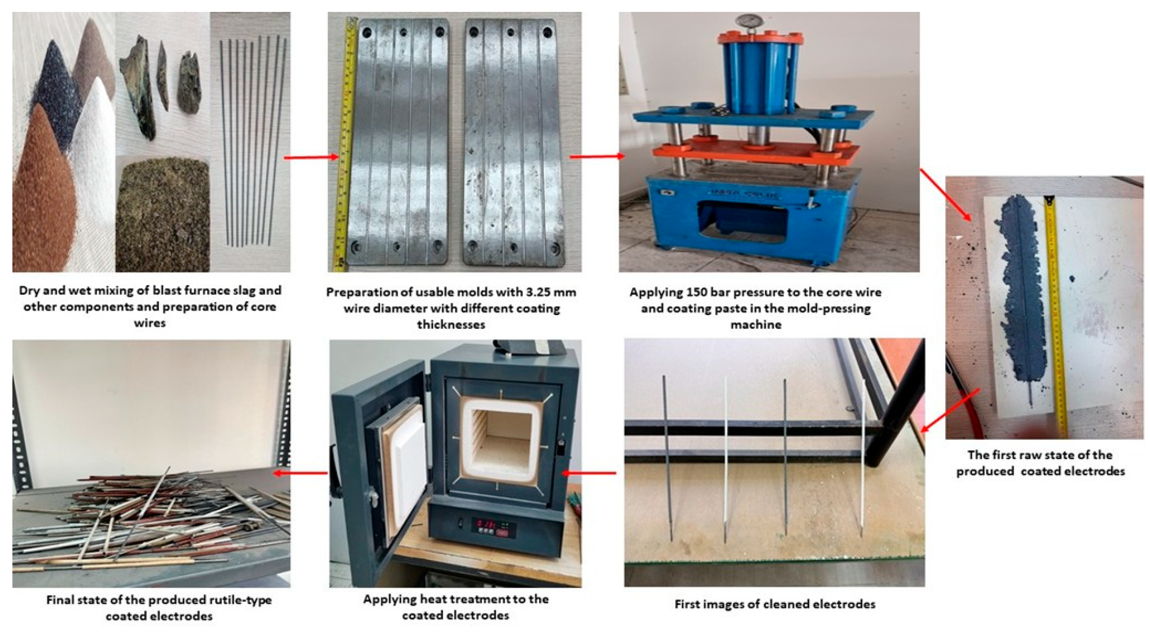
Rutile-type coated electrodes are widely used in shielded metal arc welding due to their versatility and ability to deliver consistent weld quality. The rutile-based coating works in conjunction with the core wire to provide arc stability, alloying elements, and protection to the weld pool. In this study, a mold-pressing method was selected for electrode production due to its cost-effectiveness, precision, and suitability for laboratory-scale fabrication, compared to conventional industrial methods such as extrusion and dipping [16,17,18,19,20,44,45,46]. Electrodes were produced with a 3.25 mm core wire diameter, 35 cm length, 5.17 mm total diameter, and 1.92 mm coating thickness, weighing 23 g for the core wire and 12 g for the coating, totaling 35 g per electrode. While extrusion and dipping are common in industrial applications, mold-pressing was adopted here for its practicality and alignment with extrusion-based techniques. The dipping method, which relies on surface tension for adhesion, often results in non-uniform coating thickness and potential separation of heavy metals in the liquid phase. Achieving thicker coatings via dipping requires multiple cycles, increasing production time and cost. In contrast, the mold-pressing method uses a paste-like coating formulation, allowing precise control of coating thickness through mold adjustments and delivering homogeneous coatings in a single cycle. Applying controlled pressure during molding ensured consistent coating thickness and precise dimensional conformity. The core wire conducts welding current, facilitates arc formation, and melts to form the weld metal, while both the wire and coating contribute alloying elements to the weld deposit. Electrode coating production began with the homogenization of dry materials in a Z-bladed rotary mixer for 15 min. A binder (20–30% by weight) and a small amount of water were added, followed by 15 min of wet mixing to achieve a paste-like consistency. The coating paste and core wires were loaded into a mold-pressing machine lined with transparent plastic sheets to prevent adhesion. Pressing was conducted at 150 bar to achieve the desired thickness. Excess material was removed, and pressing/cleaning steps were repeated three times for uniformity. Coated electrodes were air-dried at room temperature for 24 h, followed by heat treatment at 150 °C for two hours in a Magma Therm laboratory furnace (Tetra Isı Sistemleri Ltd., İstanbul, Türkiye) to enhance mechanical integrity and coating stability. The final flux ratios of the coated electrodes are presented in Table 3, and the production flowchart is illustrated in Figure 2. Incorporating 35–50% BFS by weight represents the highest feasible proportion for rutile-type coated electrodes, ensuring coating integrity and optimal welding performance.

2.4. Welding Tests of Rutile-Type Coated Electrodes Containing BFS

The rutile-type coated electrodes, produced via the mold-pressing method, were tested on 20 × 100 × 3 mm SAE 1020 steel plates to evaluate welding and coating performance. Welding operations were performed using a MegaStick 501M2000MF electric arc welding machine (Magmaweld, Manisa, Türkiye), employing the bead-on-plate technique for initial characterization. This method enabled visual inspection of weld quality and slag behavior derived from the coating. Bead-on-plate samples were used for all characterization processes except tensile and Izod V-notch impact tests, which utilized specially prepared butt weld samples following established methodologies [47,48]. These prior studies validated the suitability of butt weld samples for mechanical testing. Welding parameters and variables affecting coating performance were systematically controlled, with details summarized in Table 4. These include electrode dimensions, coating thickness, current range, polarity, welding angle, and substrate specifications. The selected welding parameters—including current range, polarity, and substrate type—were chosen to reflect typical industrial conditions and ensure consistent electrode performance. Preliminary tests identified electrodes with optimal performance, assessed through visual inspection and mechanical analyses. Selected electrodes underwent comprehensive testing to confirm their practical applicability. The dual approach—bead-on-plate for initial assessments and butt weld samples for mechanical evaluations—minimized external variability and enabled robust characterization of coating performance.

2.5. Microstructure, XRD, and Chemical Composition Analyses

Microstructural examinations were performed on weld samples (originally 20 × 100 × 3 mm), cut into 20 × 5 × 5 mm dimensions (weld metal height ~2 mm) and subjected to metallographic preparation. Sanding was conducted using progressively finer grit papers (80 to 1200), followed by polishing with 3 µm and 1 µm diamond paste. Samples were etched with 2% nital solution (98% ethyl alcohol, 2% nitric acid) for 10 s and examined using a Tronic XJL-17AT inverted trinocular metallurgical microscope.
Chemical composition analyses of the weld metal were performed using an Oxford Instruments optical emission spectrometer (Oxford Instruments, Abingdon, UK) for elemental quantification, and a JEOL JMS-7001F SEM (15 kV) with EDX capabilities (JEOL Ltd., Tokyo, Japan) for semi-quantitative analysis of trace elements and distribution patterns. XRD phase analysis was conducted using a Rigaku RadB-Dmax2 device (Rigaku Corporation, Tokyo, Japan) with CuKα radiation at room temperature to identify crystallographic phases in the weld metal and slag, providing insights into structural and chemical characteristics.

2.6. Hardness Measurements

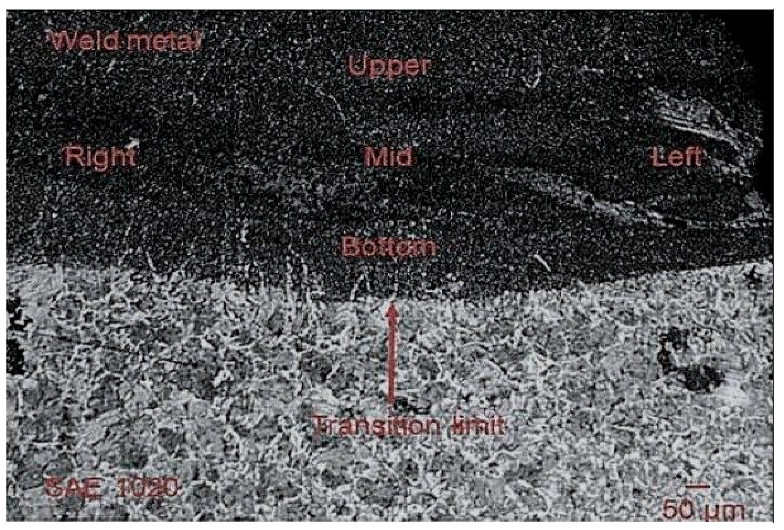
Hardness measurements were conducted on the same 20 × 5 × 5 mm samples used for microstructural analysis. A Tronic DHV-1000 Digital Vickers Hardness Tester (Tronic Instruments, İstanbul, Türkiye) applied a standardized 9.8 N load for consistent evaluation. Measurements were taken from five distinct regions of the weld metal, including the centerline and boundary zones (Figure 3), to account for localized variations. Averaged results provided a comprehensive assessment of hardness distribution, supporting the mechanical evaluation of rutile-type coated electrodes containing BFS.

2.7. Tensile and Impact Tests

Mechanical properties of the weld metal—including yield strength, tensile strength, and elongation (A5)—were assessed using a Shimadzu-Autograph AG-X tensile testing machine (Shimadzu Corporation, Kyoto, Japan) with 50 kN capacity. Butt weld samples were machined to ISO 9018:2015 specifications [49]. Impact resistance was evaluated via Izod V-notch tests in accordance with ISO 148-1:2016 and ASTM E23:2023 standards [50,51]. Samples (<75 mm length, 10 mm thickness) were tested using an Instron/Ceast 9350 impact machine (0.59–757 J capacity) at 0 °C and 20 °C to simulate standard and low-temperature conditions. Results were compared with ISO 2560:2020 requirements for rutile electrodes [52], providing insights into the reliability and adaptability of BFS-containing coatings. The combined tensile and impact tests enabled comprehensive mechanical characterization, correlating with microstructure, hardness, and chemical composition analyses.

2.8. Environmental and Economic Impact Assessment

Environmental and economic impacts of incorporating 35–50% BFS into rutile-type electrode coatings were assessed to quantify sustainability benefits. CO2 emission reductions from substituting virgin flux materials (e.g., SiO2, CaO, Al2O3, MgO, TiO2) with BFS were calculated using slag recycling and viscosity analysis methods [47,53,54,55]. Landfill diversion was evaluated using steel industry waste metrics [56,57], and economic savings were estimated based on regional disposal fees [50,57].
Cost reductions from BFS substitution were determined by comparing market prices of virgin flux materials and energy savings benchmarked against embodied energy reductions in similar recycling processes [58]. These assessments align with the EU Green Deal’s goals for climate neutrality and circular manufacturing [14].

3. Results and Discussion

3.1. Visual Inspection Results of the Produced Rutile-Type Coated Electrodes

The performance of rutile-type coated electrodes, incorporating BFS, was evaluated through a detailed visual inspection of welds and coating-derived slag properties formed during and after welding. These evaluations were systematically scored based on performance criteria outlined in Table 5—(a), focusing on critical parameters such as arc stability, burning characteristics of the core wire, spatter generation, smoothness and uniformity of the coating-derived slag layer on the weld metal, spontaneous slag removal, seam appearance, odor, smoke generation, and pore presence in the weld seam. Each coated electrode’s performance was scored on a 1–10 scale, with thresholds defined as follows:1–4: Evaluated as “unsuccessful.”, 5–6: Evaluated as “improvable.”, 7–10: Evaluated as “successful.”
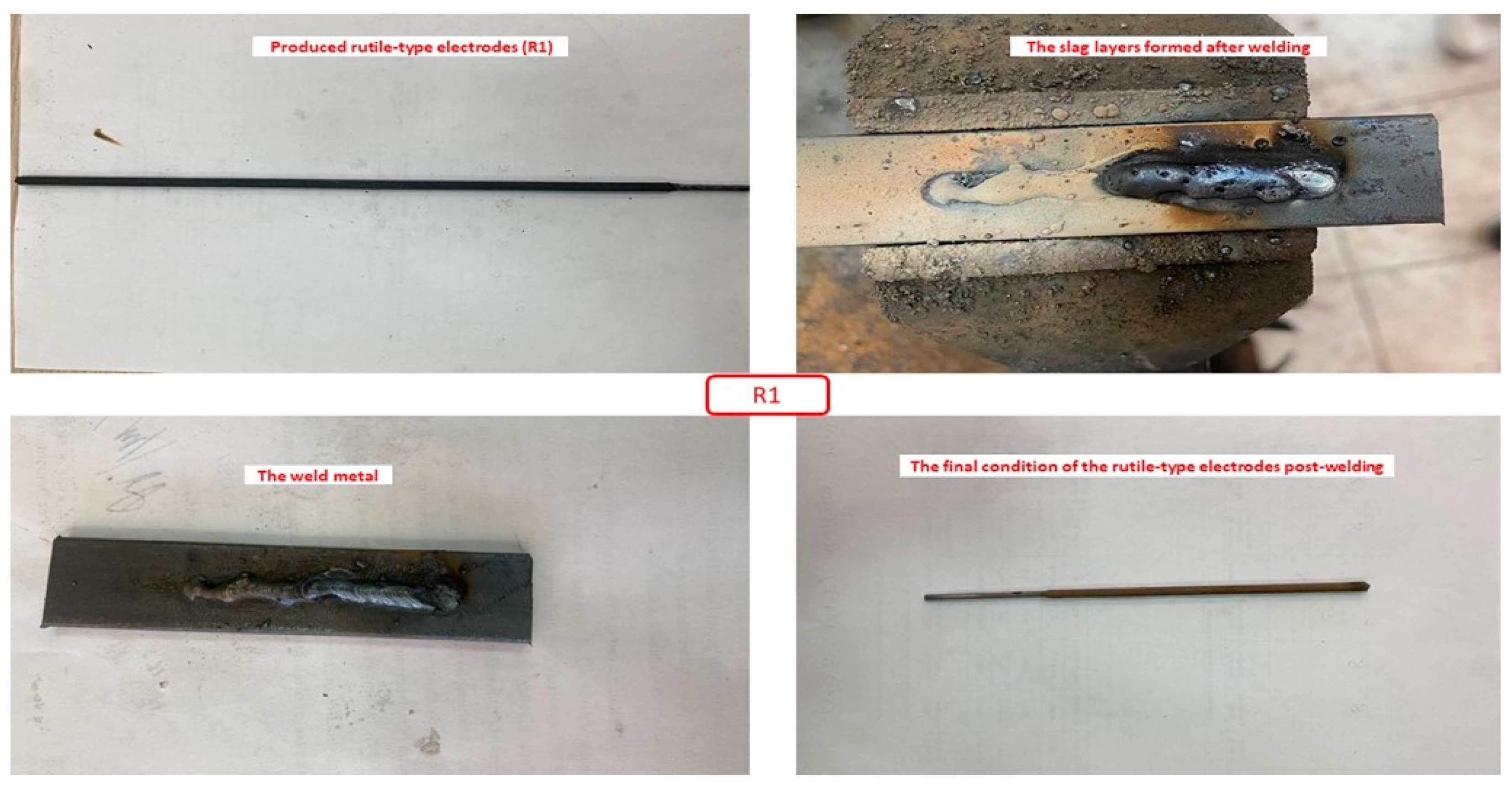
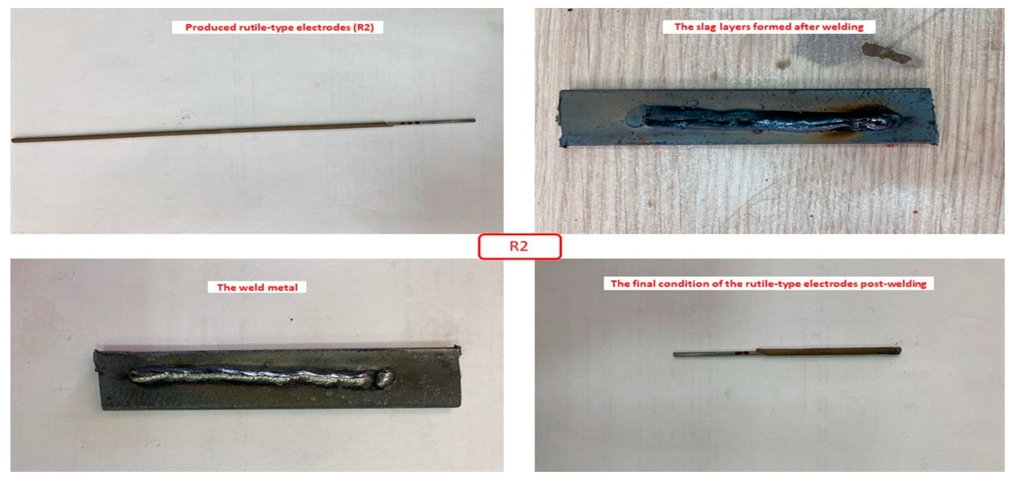
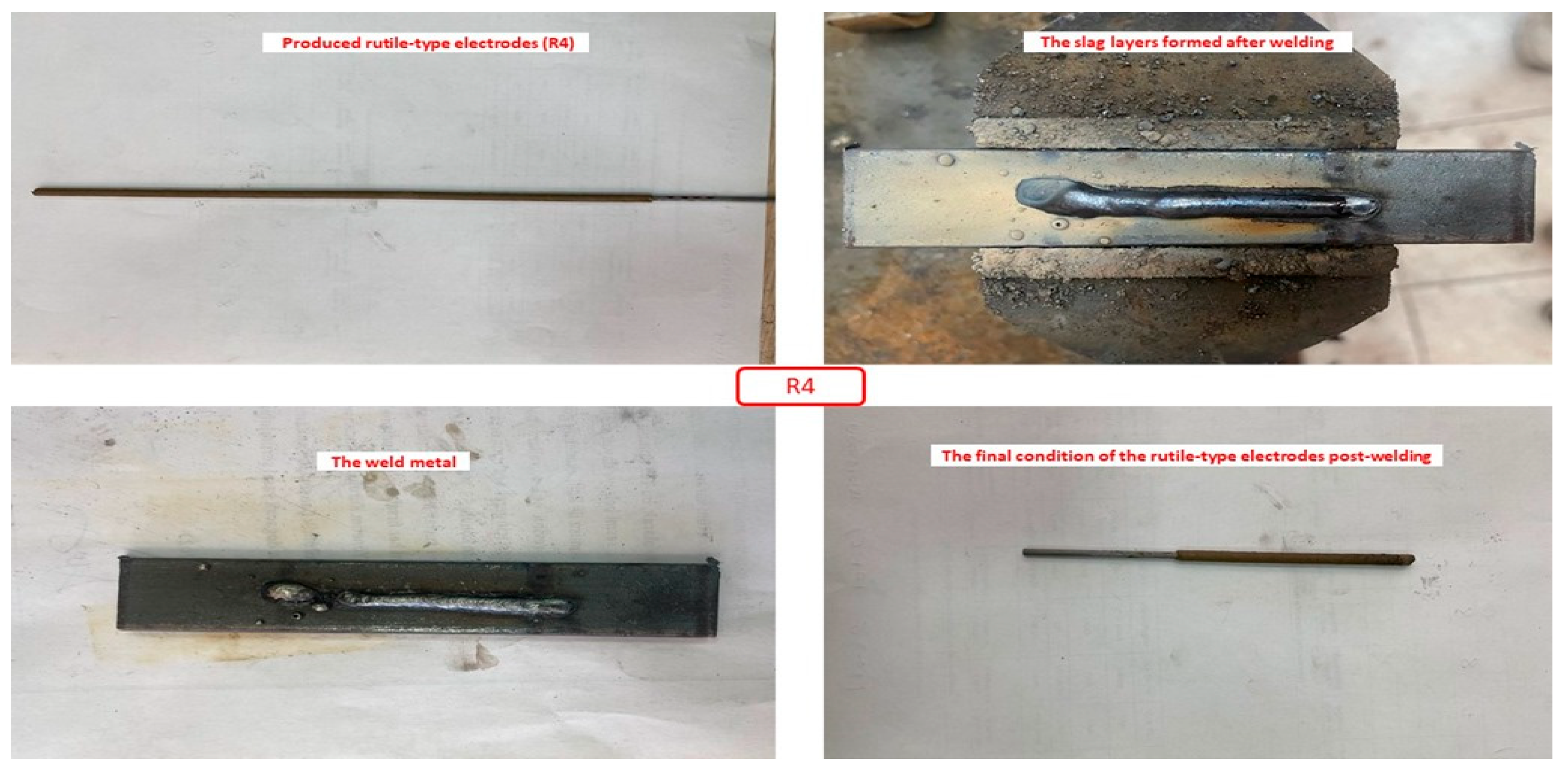
This scoring system provided a quantitative framework to assess the suitability of the coated electrodes for practical coating applications, capturing both welding performance (e.g., arc stability, burning behavior) and weld quality influenced by the coating (e.g., seam appearance, slag removal). Figure 4, Figure 5, Figure 6 and Figure 7 illustrate welding test results for electrodes R1 (50% slag, Figure 4), R2 (45% slag, Figure 5), R3 (40% slag, Figure 6), and R4 (35% slag, Figure 7), showcasing visual appearance, coating-derived slag layers, weld metal characteristics, and post-welding electrode condition. These images complemented the scoring process, offering visual insights into coating performance. The electrode application performance results, summarized in Table 5—(b), revealed significant differences in coating behavior and quality, with the scoring system effectively distinguishing superior, moderate, and poor performance based on visual criteria. Electrodes scoring 7–10 demonstrated consistent arc stability, minimal spatter, smooth coating-derived slag formation, and spontaneous slag removal, marking them as highly suitable for practical welding and coating applications.
In contrast, electrodes scoring below 5 exhibited deficiencies such as inconsistent arc behavior, excessive spatter, and poor seam appearance, highlighting areas for coating optimization. This visual inspection process provided a comprehensive understanding of the welding behavior and quality of rutile-type coated electrodes, laying a foundation for further development of coating formulations containing BFS. The visual inspection analysis, detailed in Table 5—(b), confirmed the successful performance of rutile-type coated electrodes incorporating BFS. During welding tests, arc stability was consistently rated “very good” or “excellent,” and the electrodes exhibited “very easy” burning performance, indicating high usability. Spatter formation was minimal, and coating-derived slag smoothness, except for electrode R1, was rated “very good.” The slag was spontaneously removed, enhancing operational efficiency. Weld seams displayed a “glossy” to “very glossy” appearance, with low odor and smoke levels during welding. Partial porosity was observed in the coating-derived slag of electrodes R1 and R2, but no pores were detected in other electrodes or weld metals. Scores ranged from 7 to 10, indicating overall success for electrodes R1–R4, with R3 and R4 (35–40% slag) showing superior slag smoothness and minimal porosity compared to R1 and R2. These results align with commercial market standards and literature findings on rutile-type coatings [16,17,18,19,20,44,45,46,52]. Despite these positive outcomes, certain limitations were noted. Porosity and reduced slag smoothness in electrodes R1 and R2 highlighted areas for coating improvement. The success is attributed to the optimized chemical composition of the coating formulation, ensuring compatibility with slag properties and weld metal characteristics. However, challenges such as operator inexperience, which affected electrode coating application techniques and slag formation, electrode eccentricity from the mold-pressing method causing minor uniformity issues, deoxidizer deficiencies in the coating contributing to porosity, and moisture presence impacting combustion and slag behavior, were identified as factors influencing weld quality. These findings underscore the balance between optimized coating composition and technical challenges in coated electrode production. Nevertheless, this study validates the feasibility of incorporating BFS into rutile-type coating manufacturing, establishing a basis for further refinement and optimization.

3.2. Microstructure, XRD, and Chemical Composition Analysis Results

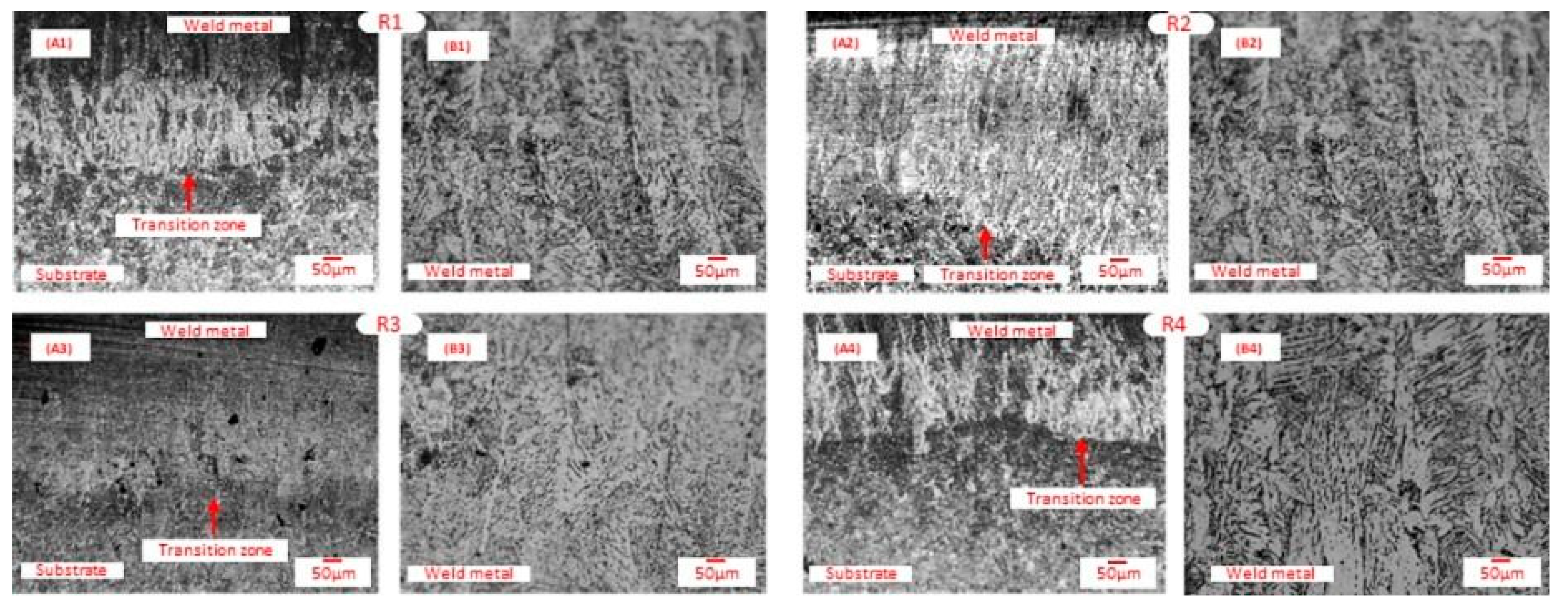
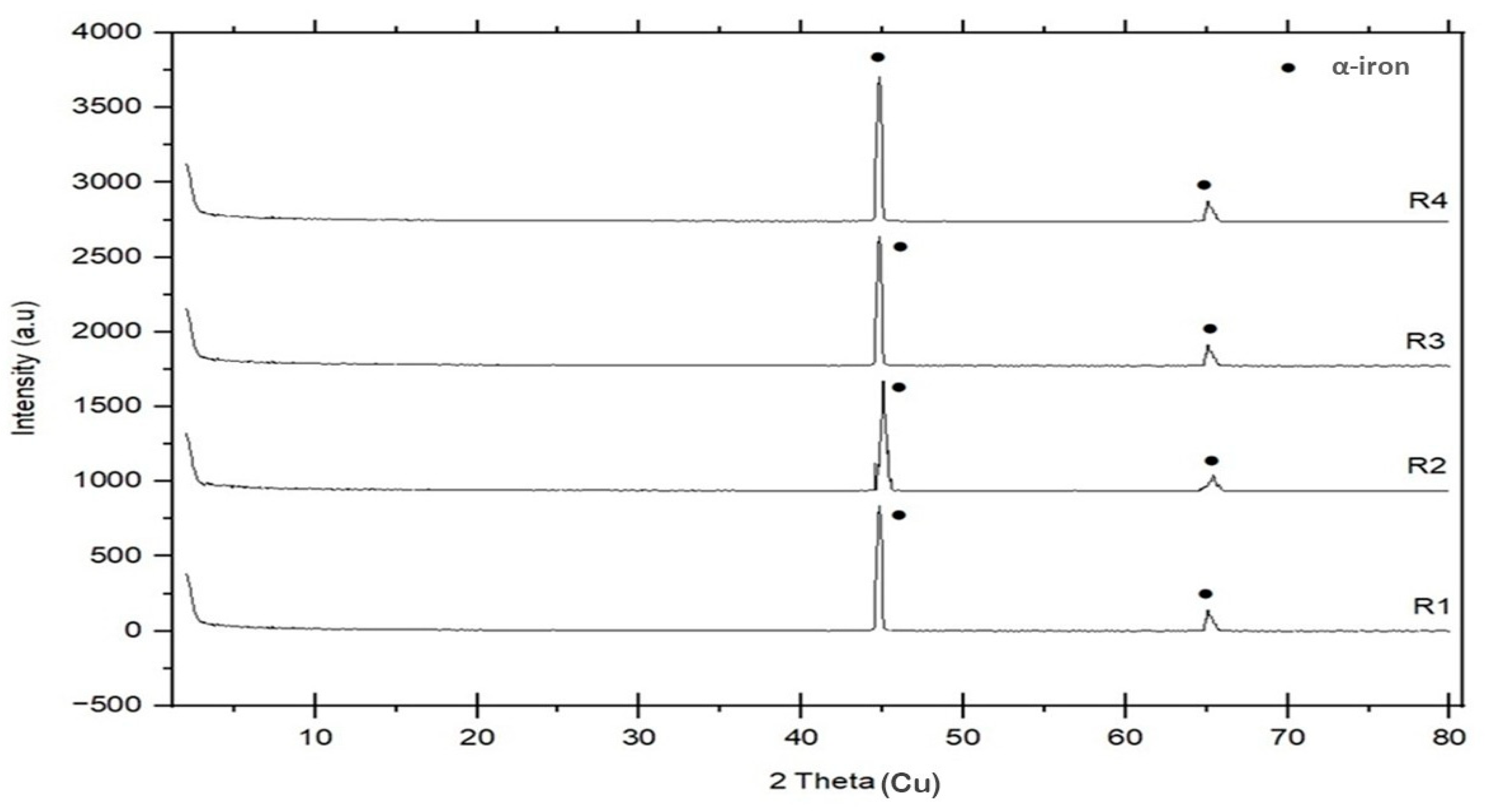
Welding tests using rutile-type coated electrodes developed in this study revealed a predominant ferrite + pearlite phase mixture in the weld metal, primarily composed of ferrite (α-iron), influenced by the electrode coating formulation. This microstructure, characteristic of weld metals produced under similar conditions, balances mechanical strength and ductility, aligning with industry benchmarks for coating performance [15]. The observed microstructures were validated through microstructure photographs (Figure 8), weld metal XRD analyses (Figure 9), and chemical composition analyses (Table 6), consistent with literature and commercial coated electrode standards [16,17,18,19,20,44,45,46,52]. The ferrite phase, forming the weld metal matrix, contributed to softness and ductility, while the pearlite phase, with its lamellar ferrite-cementite structure, enhanced strength and hardness. Uniform phase distribution, achieved through controlled welding parameters, minimized segregation and ensured coating-driven homogeneity.
Microstructure photographs (Figure 8) displayed distinct phase boundaries and consistent thermal conditions, while XRD analysis (Figure 9) confirmed dominant ferrite with trace pearlite phases, evidenced by α-iron peaks. The weld metal microstructure, comprising approximately 88.1% α-iron and 11.9% Fe3C, corroborated XRD results and aligned with established metallurgical data [59]. These phase analyses underscored the reliability of the coating process in delivering predictable structural properties [16,17,18,19,20,44,45,46]. Chemical composition analysis (Table 6) revealed a predominantly iron (Fe) weld metal with trace amounts of carbon (C), manganese (Mn), silicon (Si), sulfur (S), phosphorus (P), and other alloying elements, influenced by the rutile-type coating. As the BFS content in the coating increased, sulfur (0.023–0.026 wt%) and phosphorus (0.027–0.030 wt%) levels rose slightly, likely due to elemental transfer from the slag into the weld pool.
Conversely, manganese (1.06–1.19 wt%) and silicon (0.25–0.47 wt%) contents rose as slag content decreased, reflecting enhanced transfer efficiency from the core wire and coating formulation [16,17,18,19,20,44,45,46]. Carbon content, critical for steel, ranged from 0.11 to 0.13 wt%, decreasing slightly with reduced slag content due to carbon-oxygen reactions forming CO2 [40,41].
Measurements were conducted using an optical emission spectrometer, ensuring high accuracy. SEM-EDX analysis provided semi-quantitative oxygen content data, showing a decline in oxygen levels as slag content in the electrode coating decreased. This reduction minimized oxide and inclusion formation, enhancing weld metal ductility and toughness, critical for coating performance [32,33,34]. Nitrogen measurements, consistent across electrodes, were deemed insignificant and unrelated to coating flux content. Optimizing flux and slag content in the coating formulation proved essential for superior weld metal quality.
The results were driven by the chemical similarity between the core wire and substrate, ensuring uniform weld metal properties, and optimized welding conditions promoting a homogeneous ferrite-pearlite microstructure. Limited filler metal transfer reinforced the core wire and substrate’s role in weld metal composition, aligning with literature and commercial coating benchmarks [16,17,18,19,20,44,45,46].
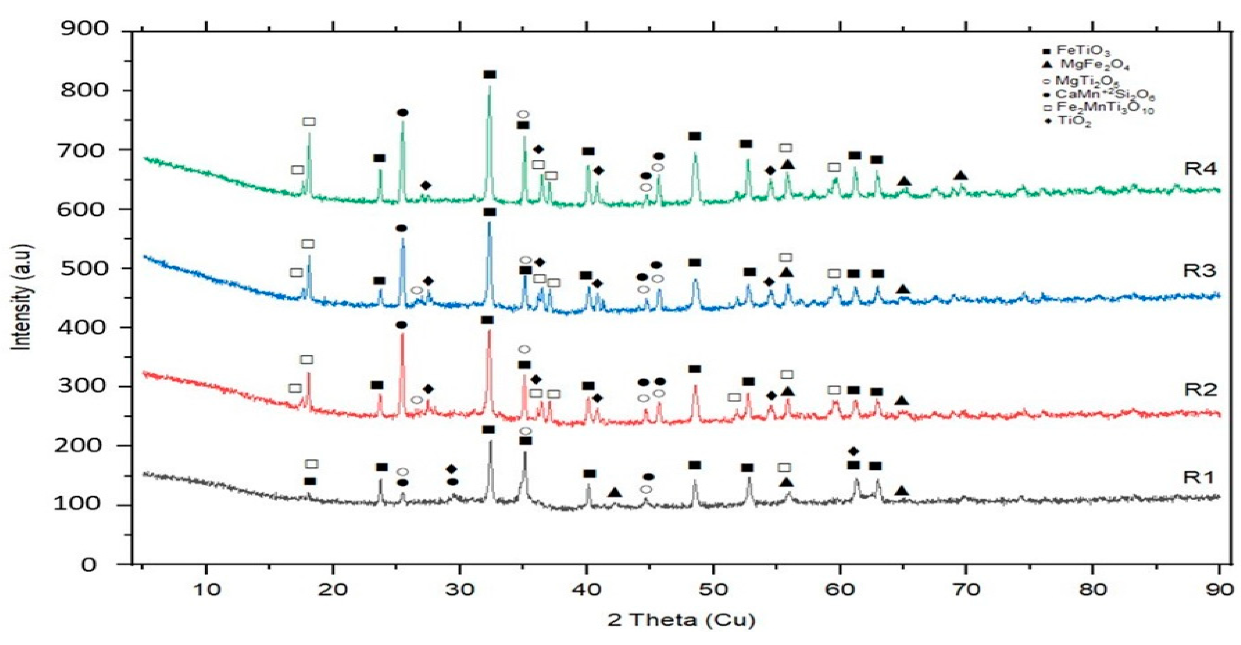
XRD analysis of coating-derived slags revealed crystalline phases, including FeTiO3 (nigrine), MgFe2O4, MgTi2O, CaMn2Si2O, Fe2MnTi3O10, and TiO2 (rutile) (Figure 10), influenced by the electrode coating’s chemical composition and thermal conditions [36,37]. Some of these phases, such as MgTi2O, CaMn2Si2O, and Fe2MnTi3O10, were tentatively identified based on peak positions and intensity ratios. Acidic phases (SiO2, TiO2, FeTiO3) enhanced coating-derived slag formation and self-lifting behavior, improving weld metal cleanliness and efficiency, while basic phases impaired these properties [16,17,18,19,20,44,45,46]. Surface tension, thermal expansion coefficients, and viscosity of these phases governed slag detachment. High-density nigrine and rutile phases promoted spontaneous slag lifting, confirmed by inspection evaluations, whereas spinel (AB2O4) and perovskite (CaTiO3) phases, with high melting points, increased slag density and viscosity, hindering removal [15,47].
Controlling these phases during electrode coating design is critical for optimizing slag behavior. Slag phase composition varied with raw material proportions in the coating formulation, aligning with industry standards and commercial coated electrode specifications [16,17,18,19,20,44,45,46]. These findings validate the optimized coating formulations and their suitability for practical welding applications.

3.3. Hardness Measurement Results

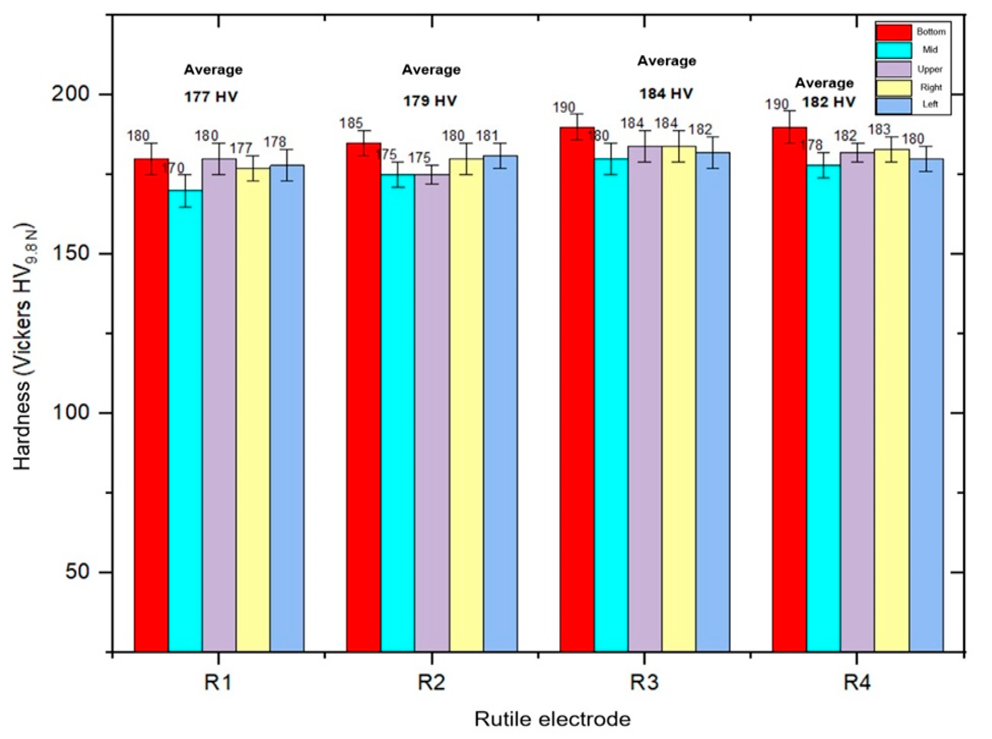
Hardness measurements conducted on weld metal samples revealed consistent mechanical behavior across electrodes containing 35–50% BFS. Vickers hardness values, obtained using a 9.8 N load, were averaged from five distinct regions of each weld metal sample to account for localized variations. As shown in Table 7 and Figure 11, hardness values ranged from 168 to 182 HV, with electrodes R3 and R4 (35–40% BFS) exhibiting slightly higher hardness due to optimized slag composition and reduced porosity.
The weld centerline consistently exhibited the highest hardness, attributed to thermal concentration and accumulation of alloying elements during welding. Boundary regions displayed marginally lower values, reflecting thermal gradients and dilution effects. The uniform distribution of hardness across samples confirmed the homogeneity of the ferrite-pearlite microstructure and effective flux-metal interaction. These results align with literature benchmarks for rutile-type coated electrodes and validate the mechanical integrity of BFS-containing coatings [16,17,18,19,20,44,45,46].

3.4. Tensile and Impact Test Results

Tensile tests performed on butt weld samples demonstrated that electrodes containing 35–40% BFS achieved yield strengths of 477–482 MPa, tensile strengths of 570–573 MPa, and elongation ratios (A5) of 24–26%, as summarized in Table 8. These values meet the ISO 2560:2020 standard requirements for rutile-type electrodes, confirming their suitability for structural welding applications [52].
Izod V-notch impact tests conducted at 0 °C and 20 °C revealed impact energies ranging from 58 to 59 J for R3 and R4 electrodes, indicating excellent toughness under standard and low-temperature conditions. Electrodes R1 and R2 (45–50% BFS) showed slightly reduced impact performance, attributed to increased porosity and slag viscosity.
The combined tensile and impact results confirm the mechanical reliability of BFS-containing rutile-type coatings. The optimized flux composition, controlled welding parameters, and effective slag behavior contributed to enhanced strength, ductility, and toughness. These findings support the feasibility of BFS integration into coated electrode manufacturing and its alignment with sustainable welding practices.

3.5. Environmental and Economic Impact Results

Incorporating 35–50% BFS into rutile-type electrodes (R1–R4) yielded quantifiable environmental and economic benefits. Environmentally, slag recycling diverted 200–600 kg of BFS per ton of steel, reducing landfill usage by 10–20% and minimizing the consumption of virgin flux materials such as SiO2, CaO, Al2O3, MgO, and TiO2 [55,56]. CO2 emissions decreased by 0.28–0.4 kg per kg of coating, as calculated in Section 2.8, based on slag recycling and the avoidance of raw material production [53,54].
Economically, BFS integration reduced raw material costs by 15–25% and coating costs by 33–48%, based on comparative market prices of virgin flux materials [46]. Landfill diversion resulted in savings of 10–20 USD per ton of steel, depending on regional disposal fee structures [50,57]. Energy savings aligned with BedZED’s steel recycling benchmarks, demonstrating significant reductions in embodied energy consumption [55].
These results are consistent with recent advances in sustainable materials engineering, where industrial and post-consumer wastes have been successfully transformed into functional systems such as foam glass structures [37], geopolymer matrices [38], and porous frameworks for adsorption-based separation [60], reinforcing the viability of circular economy strategies in metallurgical applications. These outcomes support the EU Green Deal’s 2050 climate neutrality target, while simultaneously enhancing weld quality and promoting sustainable manufacturing practices [14].

4. Conclusions

This study demonstrated the feasibility of producing rutile-type coated electrodes incorporating up to 50% BFS in four different formulations. These electrodes were evaluated through welding performance, visual inspections, microstructural and phase analyses, chemical composition assessments, and mechanical testing, including hardness, tensile strength, elongation, and impact resistance. All formulations met standard requirements for mechanical performance, with certain slag ratios showing improved strength and toughness. The results indicate that such electrodes can offer reliable performance comparable to conventional commercial alternatives. Moreover, utilizing slag as a flux component contributes to more sustainable welding practices by reducing environmental impact, conserving raw materials, and minimizing industrial waste. Future research should focus on standardizing production conditions and expanding testing to various welding configurations to enhance result reliability and broaden application potential.

Funding

This research was funded by the Scientific and Technological Research Council of Türkiye (TÜBİTAK), project number 122M824.

Institutional Review Board Statement

This study did not involve human or animal subjects; therefore, ethical approval was not required.

Informed Consent Statement

Not applicable.

Data Availability Statement

The original contributions presented in this study are included in the article. Further inquiries can be directed to the corresponding author.

Acknowledgments

The author gratefully thanks Akın Odabaşı for his contributions as a researcher, and Ümmühan Kaya and Ali İhsan Sayın for their support as TÜBİTAK scholars within the scope of Project No: 122M824. Financial support from the Scientific and Technological Research Council of Türkiye (TÜBİTAK) under Project No: 122M824 is also gratefully acknowledged.

Conflicts of Interest

The authors declare no conflict of interest.

References

  1. U.S. Geological Survey. Iron and steel slag. Mineral Commodity Summaries. 2024. Available online: https://pubs.usgs.gov/periodicals/mcs2024/mcs2024-iron-steel-slag.pdf (accessed on 6 October 2025).
  2. Reuter, M.A.; Xiao, Y.; Boin, U. Recycling and environmental issues of metallurgical slags and salt fluxes. In Proceedings of the VII International Conference on Molten Slags, Fluxes and Salts, Cape Town, South Africa, 25–28 January 2004; pp. 349–356. [Google Scholar]
  3. Giergiczny, Z. Fly ash and slag. Cem. Concr. Res. 2019, 124, 105826. [Google Scholar] [CrossRef]
  4. Oge, M.; Ozkan, D.; Celik, M.D.; Sabankaya, G.; Gok, M.S. An overview of utilization of blast furnace and steelmaking slag in various applications. Mater. Today Proc. 2019, 11, 516–525. [Google Scholar] [CrossRef]
  5. Buddhdev, B.G.; Timani, K.L. Critical review for utilization of blast furnace slag in geotechnical applications. In Problematic Soils and Geoenvironmental Concerns; Gali, M.L., Rao, P.R., Eds.; Springer: Singapore, 2021; pp. 103–114. [Google Scholar] [CrossRef]
  6. Zakira, U.; Zheng, K.; Xie, N.; Jin, F. Development of high-strength geopolymers from red mud and blast furnace slag. J. Clean. Prod. 2023, 383, 135439. [Google Scholar] [CrossRef]
  7. Yang, J.; Xiao, B. Development of unsintered construction materials from red mud wastes produced in the sintering alumina process. Constr. Build. Mater. 2008, 22, 2299–2307. [Google Scholar] [CrossRef]
  8. Cechin, L.; Ceron, C.; Oliveira, M.; Oliveira, A.; Souza, R.; Hotza, D. Ceramic composites from iron ore and blast furnace slag. Ceram. Int. 2021, 47, 10785–10791. [Google Scholar] [CrossRef]
  9. Cheah, C.B.; Tan, E.L.; Ramli, M. Recent advances in slag-based binder and chemical activators derived from industrial by-products: A review. Constr. Build. Mater. 2021, 272, 121657. [Google Scholar] [CrossRef]
  10. Liu, Y.; Zhang, Z.; Hou, G.; Yan, P. Preparation of sustainable and green cement-based composite binders with high-volume steel slag powder and ultrafine blast furnace slag powder. J. Clean. Prod. 2021, 289, 125133. [Google Scholar] [CrossRef]
  11. Perná, I.; Hanzlíček, T.; Boura, P.; Lučaník, A. Application of a clay-slag geopolymer matrix for repairing damaged concrete: Laboratory and industrial-scale experiments. Mater. Test. 2017, 59, 929–937. [Google Scholar] [CrossRef]
  12. Ministry of Environment and Urbanization; Turkish Steel Producers Association. Iron and Steel Slag Report; Turkish Steel Producers Association: Ankara, Turkey, 2015; Available online: https://celik.org.tr/en/ (accessed on 6 October 2025).
  13. Gursel, A.; Kurt, A. Radiation emission during SMAW applications on SS304 and A36 steels. Mater. Test. 2014, 56, 826–830. [Google Scholar] [CrossRef]
  14. European Commission. The European Green Deal. COM(2019) 640 final. Brussels, Belgium: European Commission, 2019. Available online: https://eur-lex.europa.eu/legal-content/EN/TXT/?uri=CELEX:52019DC0640 (accessed on 6 October 2025).
  15. Balos, S.; Sidjanin, L.; Dramicanin, M.; Labus, D. Rutile electrodes enhanced with TiO2 nanoparticles. Adv. Mater. Res. 2016, 1138, 69–74. [Google Scholar] [CrossRef]
  16. ESAB. Welding Solutions. 2025. Available online: https://esab.com (accessed on 6 October 2025).
  17. Gedik Kaynak. Welding Products and Services. 2025. Available online: https://gedik.com.tr/en/welding (accessed on 6 October 2025).
  18. Kobelco Welding. Welding Technologies. 2025. Available online: https://www.kobelcowelding.nl/ (accessed on 6 October 2025).
  19. Lincoln Electric. Welding Equipment and Consumables. 2025. Available online: https://www.lincolnelectric.com (accessed on 6 October 2025).
  20. Magmaweld. Welding Products and Solutions. 2025. Available online: https://www.magmaweld.com/ (accessed on 6 October 2025).
  21. Mitelea, I.; Uţu, I.D.; Karancsi, O.; Urlan, S.D.; Crăciunescu, C.M. Investigation of the microstructure of dissimilar welds in duplex stainless steel and low alloyed steel. Mater. Test. 2019, 61, 120–124. [Google Scholar] [CrossRef]
  22. Çevik, B. Effect of welding processes on mechanical and microstructural properties of S275 structural steel joints. Mater. Test. 2018, 60, 863–868. [Google Scholar] [CrossRef]
  23. Ozdemir, U.; Sozeri, M.; Findik, T.; Kilicli, V. Effect of buttering on the wear behavior of the SMA welded hardfacing layer in a low-carbon steel. Mater. Test. 2023, 65, 494–504. [Google Scholar] [CrossRef]
  24. Uzunali, U.Y.; Cuvalci, H. Effect of welding parameters on cruciform weld joints made of armor steel. Mater. Test. 2024, 66, 364–379. [Google Scholar] [CrossRef]
  25. Karaoglanli, A.C.; Ozgurluk, Y.; Gulec, A.; Ozkan, D.; Binal, G. Effect of coating degradation on the hot corrosion behavior of yttria-stabilized zirconia (YSZ) and blast furnace slag (BFS) coatings. Surf. Coat. Technol. 2023, 473, 130000. [Google Scholar] [CrossRef]
  26. Karaoglanli, A.C. Structure and durability evaluation of blast furnace slag coatings and thermal barrier coatings (TBCs) under high temperature conditions. Surf. Coat. Technol. 2022, 452, 129087. [Google Scholar] [CrossRef]
  27. Keßler, S.; Ziehensack, E.; Gehlen, C. Performance test to evaluate the corrosion resistance of stainless steel in concrete. Mater. Test. 2019, 61, 459–466. [Google Scholar] [CrossRef]
  28. Eroglu, M. Boride coatings on steel using shielded metal arc welding electrode: Microstructure and hardness. Surf. Coat. Technol. 2009, 203, 2229–2235. [Google Scholar] [CrossRef]
  29. Vaz, C.T.; Bracarense, A.Q.; Felizardo, I.; Pessoa, E.M. Impermeable low hydrogen covered electrodes: Weld metal, slag, and fumes evaluation. J. Mater. Res. Technol. 2012, 1, 64–70. [Google Scholar] [CrossRef]
  30. Nagentrau, M.; Tobi, A.L.M.; Sambu, M.; Jamian, Z. The influence of welding condition on the microstructure of WC hardfacing coating on carbon steel substrate. Int. J. Refract. Met. Hard Mater. 2019, 82, 43–57. [Google Scholar] [CrossRef]
  31. Kocaman, E.; Kilinc, B.; Sen, S.; Sen, U. In-situ TiB2 and Fe2Ti intermetallic assisted hard coatings by Fe-Ti-B based hardfacing electrodes. J. Alloys Compd. 2022, 900, 163478. [Google Scholar] [CrossRef]
  32. Trinh, N.Q.; Le, D.K.; Tashiro, S.; Bui, H.V.; Tanaka, T. Optimization of metal transfer in rutile flux-cored arc welding through controlled CO2 concentration in argon–CO2 shielding gas. J. Manuf. Process. 2024, 124, 590–603. [Google Scholar] [CrossRef]
  33. Le, D.K.; Tashiro, S.; Trinh, N.Q.; Tanaka, T.; Bui, H.V. Elucidation of alkali element’s role in optimizing metal transfer behavior in rutile-type flux-cored arc welding. J. Manuf. Process. 2025, 139, 105–125. [Google Scholar] [CrossRef]
  34. Pradeep, A.V. Effect of blast furnace slag on mechanical properties of glass fiber polymer composites. Procedia Mater. Sci. 2015, 10, 230–237. [Google Scholar] [CrossRef]
  35. Binici, H.; Aksogan, O. The use of ground blast furnace slag, chrome slag and corn stem ash mixture as a coating against corrosion. Constr. Build. Mater. 2011, 25, 4197–4201. [Google Scholar] [CrossRef]
  36. Kumar, A.; Singh, R.; Sharma, P.; Thakur, P.; Singh, R.K. Application of Biobased Substances in the Synthesis of Nanostructured Magnetic Core-Shell Materials. Inorganics 2023, 11, 406. [Google Scholar] [CrossRef]
  37. Al-Attar, M.; Al-Khafaji, A.; Al-Zubaidi, A.; Al-Attar, A. Waste-to-Reuse Foam Glasses Produced from Soda-Lime-Silicate Glass, Cathode Ray Tube Glass, and Aluminium Dross. Inorganics 2022, 10, 1. [Google Scholar] [CrossRef]
  38. Kovářík, T.; Šoukal, F.; Všianský, D.; Vávrová, K. The Mechanical Properties of Geopolymers from Different Raw Materials and the Effect of Recycled Gypsum. Inorganics 2023, 11, 298. [Google Scholar] [CrossRef]
  39. Deutsches Institut für Normung (DIN). DIN 17145; Weldable Normalized Fine-Grain Structural Steels–Technical Delivery Conditions. Beuth Verlag: Berlin, Germany, 1983.
  40. Moore, J.J. Chemical Metallurgy; Butterworths: London, UK, 1981. [Google Scholar]
  41. Cankut, S. Extractive Metallurgy; Istanbul Technical University Publications: Istanbul, Turkey, 1972. [Google Scholar]
  42. Levenspiel, O. Chemical Reaction Engineering, 3rd ed.; John Wiley & Sons: New York, NY, USA, 1999. [Google Scholar]
  43. Gaskell, D.R. Introduction to Metallurgical Thermodynamics, 2nd ed.; Hemisphere: New York, NY, USA, 1981. [Google Scholar]
  44. Oğuz, B. Arc Welding; Oerlikon-Magmaweld Publication: Istanbul, Turkey, 1989. [Google Scholar]
  45. Anık, S.; Tülbentçi, K.; Kaluç, E. Electric Arc Welding with the Covered Electrode; Gedik Education Foundation Publications: Istanbul, Turkey, 1991. [Google Scholar]
  46. Eryürek, B. Covered Electrode Selection for Steels; Askaynak-Lincoln Electric Publications: Istanbul, Turkey, 2007. [Google Scholar]
  47. Mikhailitsyn, S.; Sheksheev, M.; Platov, S.; Emelyushin, A.; Naumov, S. Investigation of the viscosity of liquid welding slags and melts of electrode coatings. Izv. Vysshikh Uchebnykh Zavedenii, Chernaya Metall. 2018, 61, 280–287. [Google Scholar] [CrossRef]
  48. Zhang, Y.; Liu, X.; Zhou, Y.; Shi, Y. Influence of welding method on residual stress and metallography of a mild steel welded butt-joint plate. J. Constr. Steel Res. 2022, 199, 107640. [Google Scholar] [CrossRef]
  49. ISO 9018:2015; Destructive Tests on Welds in Metallic Materials—Tensile Test on Cruciform and Lapped Joints. ISO: Geneva, Switzerland, 2015.
  50. ISO 148-1:2016; Metallic Materials—Charpy Pendulum Impact Test—Part 1: Test Method. ISO: Geneva, Switzerland, 2016.
  51. ASTM E23:2023; Standard Test Methods for Notched Bar Impact Testing of Metallic Materials. ASTM International: West Conshohocken, PA, USA, 2023.
  52. ISO 2560:2020; Welding Consumables—Covered Electrodes for Manual Metal Arc Welding of Non-Alloyed and Fine-Grained Steels—Classification. ISO: Geneva, Switzerland, 2020.
  53. Fisher, L.V.; Barron, A.R. The recycling and reuse of steelmaking slags—A review. Resour. Conserv. Recycl. 2019, 146, 244–255. [Google Scholar] [CrossRef]
  54. Falsafi, M.; Fornasiero, R. Explorative multiple-case research on the scrap-based steel slag value chain: Opportunities for circular economy. Sustainability 2022, 14, 2284. [Google Scholar] [CrossRef]
  55. Cabrera-Luna, K.; Burciaga-Diaz, O.; Santana-Carrillo, J.L.; Escalante-Garcia, J.I. Environmental performance of sustainable supersulfated cements based on blast furnace slag: A life cycle study. Environ. Res. 2025, 279, 121876. [Google Scholar] [CrossRef] [PubMed]
  56. Carneiro, G.; Bier, T.; Waida, S.; Dous, A.; Heinemann, S.; Herr, P.; Charitos, A. Treatment of energy from waste plant fly-ash for blast furnace slag substitution as a supplementary cementitious material. J. Clean. Prod. 2025, 490, 144693. [Google Scholar] [CrossRef]
  57. EREF; Waste Today. Average Cost to Landfill Municipal Solid Waste in the United States in 2022 and 2023, by Region (in U.S. Dollars Per Ton). Statista. 2024. Available online: https://www.statista.com/statistics/692063/cost-to-landfill-municipal-solid-waste-by-us-region/ (accessed on 18 June 2025).
  58. Ceylan, I.; Gokdemir, H.; Cengiz, T.; Cicek, B. Development of CaO-rich blast furnace slag containing fluorine mica-based glass ceramic coatings. Ceram. Int. 2021, 47, 29988–29994. [Google Scholar] [CrossRef]
  59. Easterling, K. Introduction to the Physical Metallurgy of Welding, 2nd ed.; Butterworth-Heinemann: Oxford, UK, 1992. [Google Scholar]
  60. Pardo, N.; Moya, J.A. Prospective scenarios on energy efficiency and CO2 emissions in the European iron & steel industry. Energy 2013, 54, 113–128. [Google Scholar] [CrossRef]
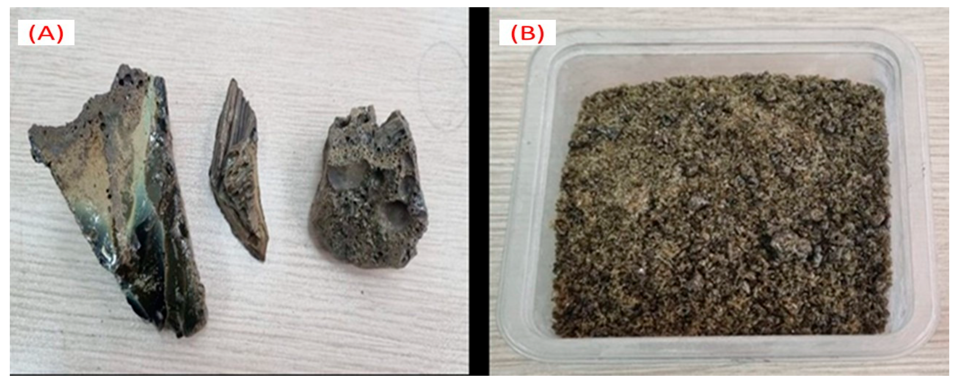
Figure 1. BFS sample. (A) Rock form, (B) Granular form.
Inorganics 13 00361 g001
Figure 2. Production process of rutile-type coated electrodes.
Inorganics 13 00361 g002
Figure 3. Hardness measurement points on the weld metal.
Inorganics 13 00361 g003
Figure 4. Weld appearance and test results for R1 rutile-type coated electrode (50% slag).
Inorganics 13 00361 g004
Figure 5. Weld appearance and test results for R2 rutile-type coated electrode (45% slag).
Inorganics 13 00361 g005
Figure 6. Weld appearance and test results for R3 rutile-type coated electrode (40% slag).
Inorganics 13 00361 g006
Figure 7. Weld appearance and test results for R4 rutile-type coated electrode (35% slag).
Inorganics 13 00361 g007
Figure 8. Microstructures related to the weld transition zone (A1A4) and weld metal (B1B4).
Inorganics 13 00361 g008
Figure 9. XRD patterns of weld metals for R1–R4 rutile-type coated electrodes.
Inorganics 13 00361 g009
Figure 10. XRD patterns of post-weld slags from rutile-type coated electrodes.
Inorganics 13 00361 g010
Figure 11. Vickers hardness measurements of weld metals for R1–R4 rutile-type coated electrodes.
Inorganics 13 00361 g011
Table 1. Chemical composition of BFS used in rutile-type electrode coatings.
MaterialSiO2CaOAl2O3MgOTiO2Na2O +
K2O
Fe2O3MnOS2−PO43−Rest
BFS39
(±0.5)
37.5
(±0.4)
12.4
(±0.2)
5
(±0.1)
1.6
(±0.2)
1.1
(±0.05)
0.9
(±0.1)
0.4
(±0.5)
0.06
(±0.01)
0.05
(±0.01)
Others
Note: Trace elements include minor components not individually listed.
Table 2. Chemical composition of core wire and SAE 1020 substrate.
Chemical Composition (wt%)
MaterialCSiCuMnPSNiCrFe
Core wire0.080.0220.0890.5440.0090.0110.0460.041Bal.
SAE 10200.200.001-0.4000.0260.022-0.064Bal.
Table 3. Formulation ratios of rutile-type coated electrodes.
Flux Ratios (wt%)
Electrode Code
(Rutile)
BFSRutile
(TiO2)
Other Flux ComponentsBinder
(K2SiO3)
Water
R15035–500–1520–251–2
R24535–500–1520–251–2
R34035–500–1520–251–2
R43535–500–1520–251–2
Note: Other flux components include silicates (SiO2 or feldspars), carbonates (CaCO3), cellulose (C6H10O5), iron powder, and deoxidizer (FeMn). Binder and water are added as percentages after the total mixture is prepared as 100%.
Table 4. Welding test parameters of rutile-type coated electrodes.
ParametersProperties
Electrode TypeRutile (Thick coating)
Electrode outer diameter (mm)5.17 mm
Electrode Core Wire Diameter (mm)3.25 mm
Electrode Core Wire weight (g)23 g
Electrode coating thickness (mm)1.92 mm
Electrode coating weight (g)12 g
Coating/Core wire (%)59
Total electrode length (cm)35 cm
Welding Machine (type)Shielded metal arc welding-SMAW
Current (A)70–100
Welding Angle (°)45
Pole (±)(+)
SubstrateSAE 1020
Substrate Dimensions (mm)20 × 100 × 3 mm
Pre-heat for substrate No
Pre-heat for electrodesNo
Table 5. Performance criteria and visual inspection results of rutile-type coated electrodes.
(a) Performance Criteria of Rutile-Type Covered Electrodes
RatingArc
Stability
BurningSpatterSlag
Uniformity
Slag
Removal
Seam
Appearance
Odor
and Smoke
Seam or Slag
Porosity
Point
1–2Very BadVery
difficult
ExcessVery
poor
Very
difficult
MattExcessVery high
3–4BadDifficultIncreasedPoorDifficultLow
gloss
LessHigh
5–6GoodMediumModerateAverageEasyMediumMediumMedium
7–8Very goodEasyMinimal GoodVery easyGlossyMinimal Low
9–10ExcellentVery
easy
NoneVery
good
SpontaneHigh
gloss
NoneNone
(b) Scores received by therutile-type coveredelectrodes
Electrode
numbers
Arc
stability
BurningSpatterSlag
uniformity
Slag
removal
Seam
appearance
Odor and smokeSeam
porosity
R1Point89779787
R21010810101088
R310108101010810
R41010810107810
Table 6. Chemical composition of weld metals from rutile-type coated electrodes.
Chemical Composition (wt%)
ElectrodeCMnSiSCrPONFe
R10.121.060.250.0260.050.0301.180.04Bal.
R20.131.080.310.0270.050.0281.060.04Bal.
R30.111.170.400.0240.050.0270.930.04Bal.
R40.111.190.470.0230.040.0270.900.04Bal.
Note: Oxygen (O), with elevated values (0.90–1.18%), and nitrogen (N) are semi-quantitative by SEM-EDX for comparison only. Other analyses use optical emission spectrometry.
Table 7. Tensile and impact test results of rutile-type coated electrodes.
Electrode NumbersYield Strength
(MPa)
Tensile Strength
(MPa)
Elongation A5 (%)Izod V-Notch Impact Strength
(Joule)
20 °C0 °C
R1470560247948
R2474562258353
R3477570268658
R4482573268659
Commercial E6013400–500500–56023–2870–10050–60
Note: R1–R4 values were obtained from single tests in this study, conducted per ISO 9018:2015, ISO 148-1:2016, and ASTM E23:2023. Commercial E6013 values are from Magmaweld (2025).
Table 8. Mechanical property requirements according to ISO 2560:2020.
Minimum Yield Strength
(MPa)
Tensile Strength Range
(MPa)
Minimum Elongation
A5 (%)
355440–57022
380470–60020
420500–64020
460530–68020
500560–72018
Disclaimer/Publisher’s Note: The statements, opinions and data contained in all publications are solely those of the individual author(s) and contributor(s) and not of MDPI and/or the editor(s). MDPI and/or the editor(s) disclaim responsibility for any injury to people or property resulting from any ideas, methods, instructions or products referred to in the content.