Review

Recent Progress of Plasmonic Perovskite Photodetectors

1
Department of Chemistry and Centre for Processable Electronics, Imperial College London, London W120BZ, UK
2
Department of Materials Science and Engineering, Sungshin Women’s University, Seoul 01133, Republic of Korea
*
Author to whom correspondence should be addressed.
Inorganics 2025, 13(11), 351; https://doi.org/10.3390/inorganics13110351
Submission received: 25 September 2025 / Revised: 23 October 2025 / Accepted: 24 October 2025 / Published: 27 October 2025
(This article belongs to the Special Issue Recent Progress in Perovskites)

Abstract

Perovskite materials have emerged as promising candidates for next-generation photodetectors (PDs) owing to their superior optoelectronic properties and compatibility with low-cost, low-temperature fabrication processes. Broad applicability of PDs spans diverse fields, including X-ray detection, wearable electronics, autonomous vehicles, artificial intelligence, imaging, optical communication, and biomedical sensing, offering advantages over conventional semiconductor PDs based on Si, Ge, InGaAs, and GaN. The integration of plasmonic nanostructures into perovskite-based devices has recently emerged as an effective strategy to enhance performance by amplifying light absorption near the perovskite layer. This review summarizes recent advances and design strategies for plasmonic-integrated perovskite photodetectors (Pe-PDs), with a particular emphasis on plasmonic nanopatterns and nanoparticles as viable approaches for solution-processable Pe-PDs.

Graphical Abstract

1. Introduction

Metal halide perovskites (MHPs) with the general formular of ABX3, where A is organic or inorganic cation (e.g., Cs+, methylammonium (MA+), or formamidinium (FA+), B is divalent metal cation (e.g., Pb2+, Sn2+, or Ge2+), and X is halide anion (e.g., Cl, Br, I) have been identified as one of the most promising materials for optoelectronic applications [1,2,3,4,5], due to their high absorption coefficient, long carrier lifetime and diffusion length, and low defect density in conjunction with ease of cost-effective solution processability [6,7,8,9,10,11]. This surge has made outstanding progress, driven by key applications ranging from photovoltaics to light-emitting diodes and flexible electronics [12,13,14,15,16].
This growing momentum has also driven significant advances in PD technologies [17], particularly in the search for alternatives to conventional semiconductor PDs based on materials such as Si, Ge, InGaAs, and GaN [18,19]. These traditional systems typically require high-temperature fabrication and are limited by their inherent rigidity. As the field moves toward flexible, lightweight, and wearable electronics, there is increasing demand for PDs that are compatible with deformable substrates and possess both mechanical adaptability and high optoelectronic performance [20,21,22,23]. In this context, perovskite materials have emerged as strong candidates for next-generation PDs [24,25,26,27,28].
Pe-PDs potentially can offer broad application potential in areas such as X-ray detection [29], wearable electronics [30], autonomous vehicles [31], artificial intelligence [32], polarized imaging [33], optical communication [34], and biomedical sensing [35] (Figure 1). For instance, the strong X-ray absorption and efficient charge transport properties of perovskites make them well-suited for integration into high-resolution, low-cost medical imaging systems. In addition, Pe-PDs hold significant potential in biomedical applications [36], including non-invasive health monitoring using near-infrared light [37], as well as ultraviolet detection for flame monitoring [38], sterilization [39], and environmental sensing [40,41]. Their compatibility with imaging systems further enables advanced functionalities such as facial recognition and self-powered operation through integration with photovoltaic components. Furthermore, recent advancements in chiral Pe-PDs have facilitated the direct detection of circularly polarized light without the need for bulky external optical components [42,43]. Collectively, these innovations underscore the versatility and transformative potential of Pe-PDs, paving the way for their adoption in next-generation flexible and multifunctional optoelectronic devices.
Despite the promising properties of perovskite materials, significant challenges remain in advancing their PDs toward practical use. A key obstacle lies in achieving balanced device performance suited for real-world applications, which demand rapid and precise detection of fluctuating signals over a wide range of intensities [44]. To meet these requirements, an ideal PD must concurrently deliver a high signal-to-noise ratio (SNR), a broad linear dynamic range (LDR), and ultrafast response speed [45]. Extensive efforts have been devoted to improving the performance of Pe-PDs by addressing key challenges through strategies such as compositional and additive engineering to suppress bulk and surface defects [46,47], interface engineering using thin buffer layers [48,49], and the introduction of perovskite–organic heterojunction structures [50]. While these material- and interface-driven approaches have yielded notable improvements, they still fall short of fully meeting the stringent performance requirements needed for practical and commercial applications.
Recently, plasmonic-enhanced Pe-PDs have emerged as a promising strategy to surpass the limitations of conventional perovskite-based devices [51,52]. Incorporating plasmonic nanoparticles or nanostructures into the perovskite active layer or the adjacent charge-collection layer significantly amplifies the local electromagnetic field, enhancing light–matter interactions and boosting photon absorption [53,54,55,56,57]. This approach effectively addresses the challenge of insufficient light absorption in thin perovskite layers, which can otherwise limit device sensitivity and efficiency. Furthermore, plasmonic structures can be precisely engineered to exhibit wavelength-specific resonances, enabling spectral tuning and improved detection selectivity [58]. The resulting strong near-field enhancement also facilitates faster carrier generation and separation [59], contributing to quicker photoresponses and better spectral discrimination. Overall, the integration of plasmonics leads to more efficient light harvesting, enhanced detection sensitivity, faster response times, and greater spectral tunability, collectively overcoming many of the limitations of traditional Pe-PDs.
In this review, we provide a comprehensive discussion focused on three main structures: (1) an overview of viable strategies for integrating plasmonics into Pe-PDs, along with a concise introduction to the two principal plasmonic modes; (2) a division of two types of plasmonic structures: plasmonic nanopatterns and plasmonic nanoparticles (NPs), and their respective impacts on device performance, highlighting their potential in PD applications; and (3) emerging perovskite optoelectronics associated with incorporating chiral plasmonic structures into perovskite optoelectronic devices for advanced light-matter interaction.

2. Introduction of Plasmonics

Plasmonics exploits the collective oscillations of free electrons, excited by electromagnetic radiation, at the interface between metallic and dielectric materials. These oscillations, known as surface plasmons, give rise to surface plasmon resonance (SPR), which enables the confinement and manipulation of light at dimensions well below the diffraction limit [60,61]. This capability has opened new avenues in optical sensing, high-resolution imaging, and the development of advanced photonic and optoelectronic devices [51].
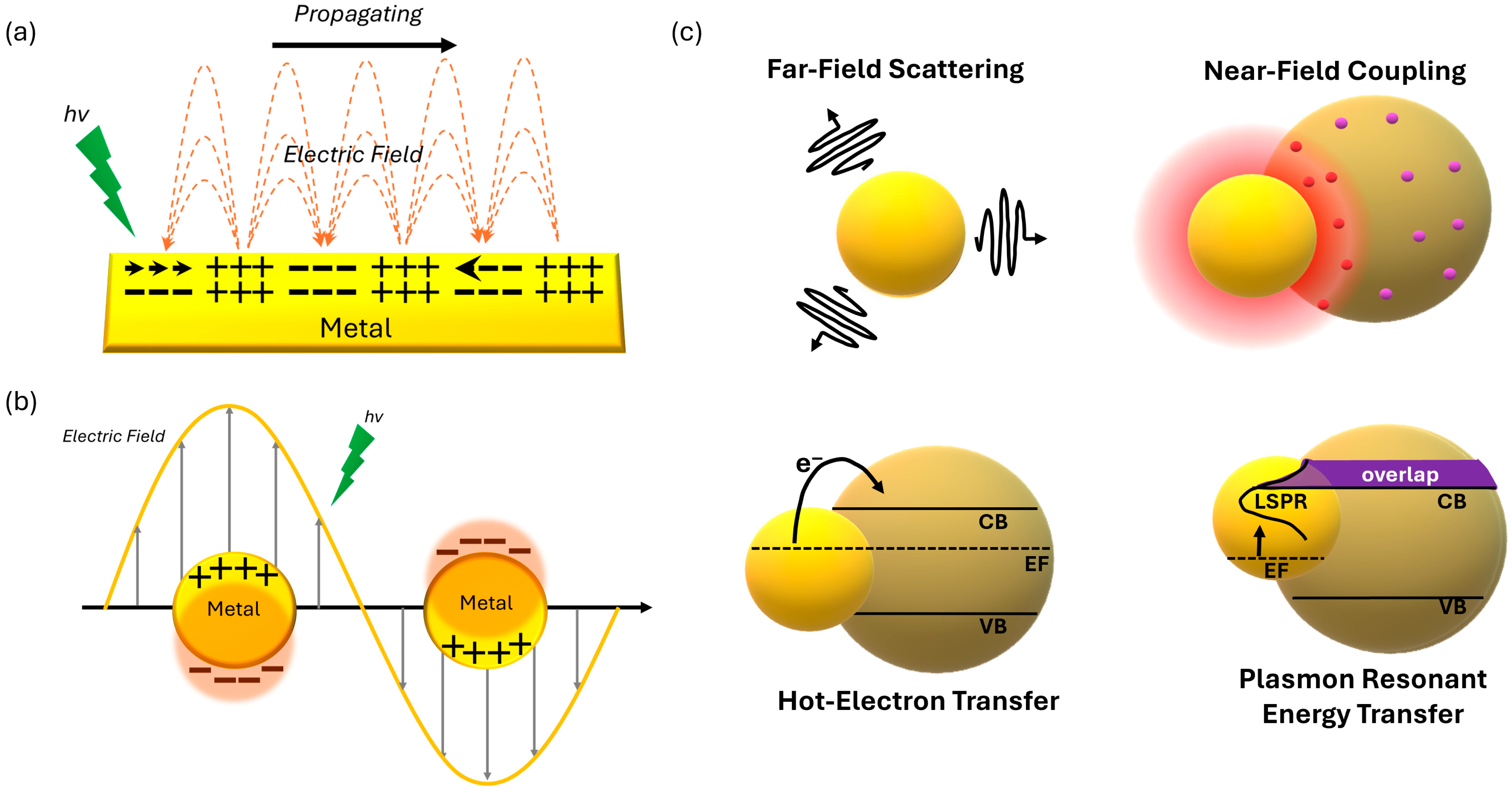
Two principal plasmonic modes are typically distinguished: surface plasmon polaritons (SPPs) and localized surface plasmon resonances (LSPRs). SPPs are electromagnetic waves confined to the metal–dielectric interface, propagating along the surface while tightly binding light and electronic oscillations [62] (Figure 2a). These waves facilitate extreme electromagnetic field enhancement up to 105-fold and subwavelength light confinement, making them especially promising for use in thin-film plasmonic optoelectronic devices and PDs. Integrating plasmonic nanostructures directly into the active layer through pattern transfer techniques such as imprinting lithography [63,64] allows the formation of plasmonic features directly on the light-harvesting surface. This approach can significantly amplify optical absorption by enhancing light–matter interaction.
In contrast, LSPRs result from non-propagating electron oscillations confined within metallic nanoparticles (NPs) (Figure 2b). These localized resonances generate intense electromagnetic fields in the immediate vicinity of the nanoparticles, with field enhancement localized within just a few nanometers of the surface. The optical response of LSPRs is highly sensitive to nanoparticle size, shape, and material composition, allowing their resonant frequencies to be precisely tuned across the ultraviolet to infrared spectrum [65]. Strategically positioning these plasmonic nanoparticles, such as embedding them in buffer layers or within the photoactive layer, can enable efficient coupling of the enhanced near fields into adjacent photoactive regions, thereby boosting light absorption and improving device performance. Altogether, plasmonic strategies based on SPP, LSPR, or their combination have emerged as powerful tools for improving the performance of optoelectronic devices and advancing next-generation sensing technologies. Key mechanisms contributing to plasmonic enhancement in perovskite optoelectronics mainly include far-field light scattering, near-field coupling, and plasmon-driven resonant energy transfer or hot electron transfer (HET) from metals to semiconductors (Figure 2c) [66,67,68,69,70]. In far-field light scattering events, which are representative of plasmonic effects in Pe-PDs, radiative decay involves intense light scattering away from the plasmonic nanostructures. Far-field scattered light effectively extends the optical path length within the photoactive layer, thereby enhancing light absorption [63,68,69,71]. The HET mechanism involves generating energetic hot electrons inside metal nanoparticles such as gold and silver. These hot electrons are produced either by excitations within the metal’s conduction band or through transitions from the d-band to the conduction band [72]. Before these hot electrons lose energy, they can be effectively transferred into a semiconductor material by crossing a Schottky barrier formed at the metal-semiconductor interface, thus facilitating charge transfer and improving device performance [66,67,70]. Plasmon resonant energy transfer is a mechanism in which energy absorbed by a plasmonic metal from sunlight is non-radiatively transferred to a nearby semiconductor via dipole–dipole coupling, which enables directional energy flow from the metal to the semiconductor [53]. This process results in the generation of electron–hole pairs below or near the semiconductor’s band edge.

3. Figures of Merits for PDs

To evaluate the performance of a PD, several key figures of merit are typically considered, including responsivity (R), external quantum efficiency (EQE), and detectivity (D*). These parameters provide critical insights into the optoelectronic properties of the device. R quantifies the electrical response of the PD to incident light and is defined as the ratio of the photocurrent to the incident light power. It is calculated using the following Equation (1):
R = I l i g h t I d a r k P i n · S
where Ilight and Idark are the output currents under illumination and in the dark, respectively, Pin is the incident light power density, and S is the effective area of the device. External quantum efficiency (EQE) represents the ratio of the number of charge carriers collected to the number of incident photons, reflecting the PD’s photon-to-charge conversion efficiency. It is calculated as Equation (2),
E Q E = h c q λ · R
where h is Planck’s constant, c is the speed of light, q is the elementary charge, and λ is the wavelength of the incident light. D* is a critical parameter for evaluating the sensitivity of a PD, particularly under low-light conditions. It is defined as Equation (3),
D * = R S · f i n = S · f N E P
where S is the effective area, Δf is the electrical bandwidth, in is the noise current, and NEP is the noise equivalent power. NEP represents the minimum impinging optical power that a detector can distinguish from the noise. These metrics collectively provide a key assessment of a PD’s performance.
In evaluating the performance of PDs, standardized measurement conditions are essential to ensure consistency and comparability across different materials and device architectures. Typically, a bias voltage ranging from 0 to several tens of volts is applied to enhance carrier collection, though self-powered devices operate at zero bias, and higher voltages may be used in specific cases such as transistor-type or avalanche PDs. The active area of a device, which typically varies in area units between mm2 and cm2, must be accurately defined, as it directly impacts the calculation of normalized figures of merit such as D*. Noise characterization, a critical factor in determining NEP and D*, typically involves measuring the current noise spectral density (in A/√Hz) under dark conditions using low-noise current amplifiers and spectrum analyzers or lock-in techniques. Both intrinsic noise sources, such as thermal (Johnson) and shot noise, and extrinsic sources like 1/f noise, are considered [73]. Bandwidths below kHz are commonly used for noise characterization or extending into the MHz range is employed for evaluating response speed and frequency-dependent characteristics. Accurate and transparent reporting of these parameters, bias, active area, bandwidth, and noise estimation methods, is essential for reliable benchmarking and for advancing the development of high-performance PDs.

4. Plasmonic Nanoparticle-Based Pe-PDs

4.1. Perovskite–Plasmonic Nanoparticle

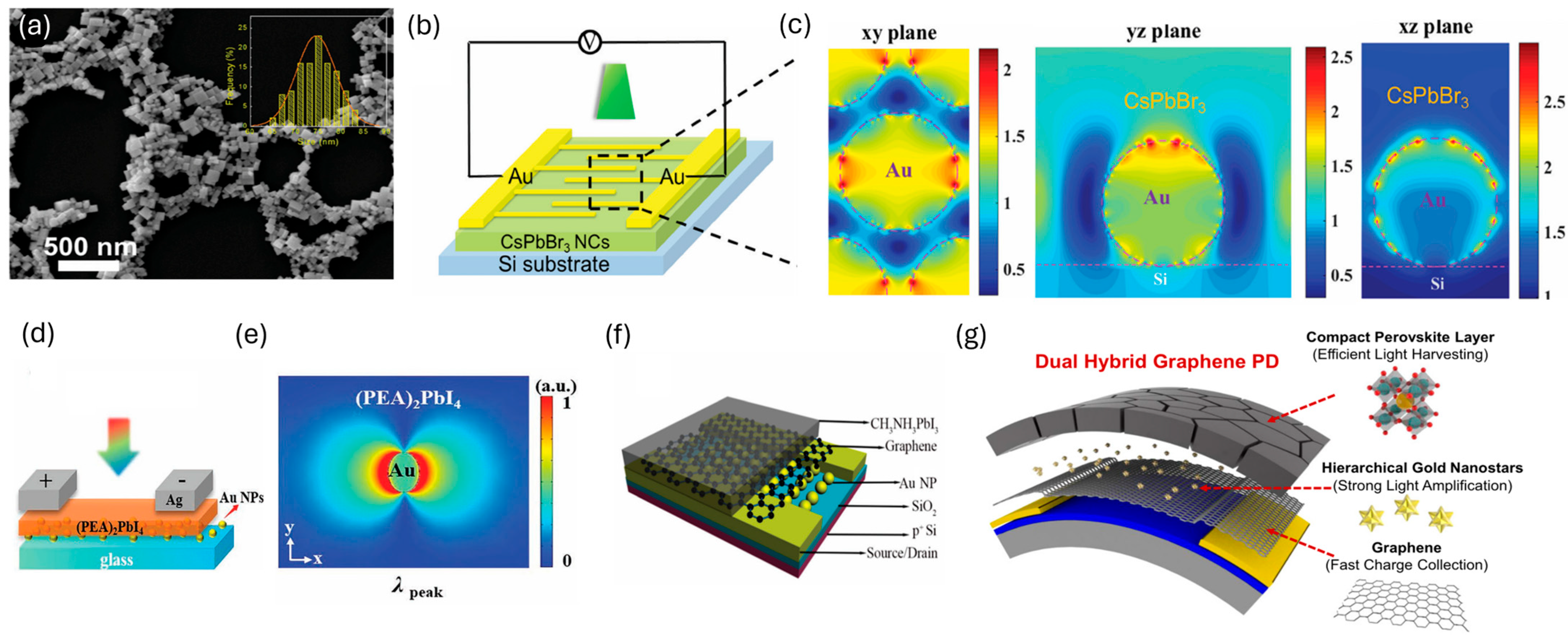
Most studies on plasmonic NP-based Pe-PDs have primarily focused on incorporating plasmonic NPs prior to the deposition of the perovskite layer. Dong et al. demonstrated a Pe-PD with enhanced optoelectronic performance by introducing all-inorganic perovskite (CsPbBr3) nanocrystals (NCs) with a preferred orientation together with gold nanoparticles (Au NPs) exhibiting LSPR effect (Figure 3a) [74]. To fabricate Pe-PDs, Au NPs were spin-coated on a Si substrate, followed by the deposition of a highly dense and uniform CsPbBr3–Au NP film via centrifugal-casting, and the placement of thermally evaporated Au electrodes (Figure 3b). The resulting Pe-PD showed enhanced both light absorption and the near-field electric field due to the LSPR effect of Au NPs through the excellent spectral overlap between the absorption peak of CsPbBr3 (520 nm) and the plasmon resonance peak of Au (530 nm) (Figure 3c). As a result, the photocurrent increased from 245.6 μA to 831.1 μA, representing 238% enhancement, while the on/off ratio rose from 1.6 × 10⁵ to 1.66 × 10⁶, and the detectivity (D*) improved from 4.56 × 10⁸ Jones to 1.684 × 10⁹ Jones. Moreover, the fabricated device demonstrated excellent stability, maintaining performance degradation within 3.2% even after more than 10,000 light on/off cycles.
Conventional 2D single-crystal-based Pe-PDs exhibit a limitation in responsivity (R), being restricted to ultraviolet and visible regions. To overcome this limitation and extend the detection capability to the telecommunication wavelength of 1310 nm, Xi et al. introduced Au NPs [75]. The device was fabricated by thermally evaporating Au NPs onto a glass substrate, transferring a (PEA)2PbI4 single crystal on top, and subsequently depositing Ag electrodes (Figure 3d). In the long-wavelength region (650–900 nm), an average external quantum efficiency (EQE) was enhanced by up to 1000%, and stable on–off electrical responses were achieved at the 1310 nm telecommunication band. Two mechanisms could explain the enhancement of photodetection performance. First, light absorption was strengthened by the local electric field generated by Au NPs, thereby increasing the photocurrent (Figure 3e). Second, in the long-wavelength region beyond the bandgap of (PEA)2PbI4, an additional photocurrent was generated through the injection of hot holes from Au NPs. From a performance perspective, the dark current was suppressed to below 100 fA, and the EQE reached 61% at 480 nm, corresponding to an enhancement factor of 68.5% compared with the control device (36.4%). The D* reached as high as 8.1 × 10¹⁴ Jones at 480 nm, representing a 68.5% improvement over the control (4.8 × 10¹⁴ Jones). Moreover, the device exhibited excellent stability, maintaining about 70% of its initial photocurrent after 33 days without encapsulation.

4.2. Perovskite–Graphene–Plasmonic Nanoparticle

Plasmonic enhancement has also been explored in hybrid Pe-PDs with 2D materials such as graphene. Sun et al. reported enhanced performance in CH3NH3PbI3 perovskite–graphene hybrid Pe-PDs by introducing Au NPs with a diameter of approximately 40 nm [76]. The device was fabricated by first defining Au electrodes on a Si/SiO2 substrate, sequentially depositing Au NPs, graphene, and a perovskite thin film, in which Au NPs were positioned beneath the graphene layer and physically separated from the perovskite. This configuration enabled the exploitation of the plasmonic effect of Au NPs without interfering with charge transport pathways in the perovskite, thereby ensuring that the observed enhancement was solely attributed to plasmonic enhancement (Figure 3f). The hybrid device containing perovskite, graphene, and Au NPs (P–G–Au) exhibited nearly twice the R and EQE compared with the control device without Au NPs (P–G), achieving a maximum R of 2 × 10³ A W−1. This enhancement was attributed to the LSPR effect of the Au NPs, which boosted light absorption in the perovskite layer and facilitated the generation of photo-induced carriers near the graphene interface. Faster and more efficient carrier extraction was enabled by shorter transport pathways. As a result, the photoresponse speed of the hybrid device was significantly improved, with the rise time reduced from 1.8 s for the P–G device to 1.5 s for the P–G–Au device, corresponding to an improvement of ~17%. These findings demonstrate that incorporating Au NPs is an effective strategy to simultaneously enhance both the responsivity (R) and response speed in perovskite–graphene hybrid PDs.
However, due to the poor affinity of the perovskite precursor solution on the graphene surface, the perovskite layer often forms in an isolated island-like morphology rather than as a dense, continuous film. To overcome this limitation, Lee et al. proposed a hybrid Pe-PD structure by incorporating gold nanostars (GNSs) into graphene–perovskite systems [77]. GNSs possessed a spherical core surrounded by multiple sharp tips, where strong local electromagnetic fields were generated at the tip ends. In this configuration, the perovskite layer acted as an efficient light absorber, graphene provided high-speed charge transport, and GNSs enhanced the local electromagnetic field, thereby enabling complementary functionality among the three components (Figure 3g). The perovskite layer was fabricated by thermal evaporation of PbI2 followed by spin-coating of MAI, which successfully yielded a dense perovskite film on graphene. The resulting device exhibited outstanding performance under blue light illumination, achieving R of 5.90 × 10⁴ A W−1 and D* of 1.31 × 10¹³ Jones, which represented the highest values reported to date for MAPbI3–graphene Pe-PDs. Compared with pristine Pe–PDs, R and D* were enhanced by 7.7 million-fold and over 100-fold, respectively. Photoluminescence (PL) quenching and enhancement analyses confirmed that the improved performance resulted from both efficient charge transfer at the graphene–perovskite interface and the LSPR effect of GNSs. Furthermore, the device fabricated on a plastic substrate demonstrated remarkable flexibility, maintaining stable operation under bending with a radius of curvature as small as 3 mm and after more than 1000 bending cycles. In addition, a flexible G–GNS–P–PD array (10 × 10) successfully enabled sensitive photomapping, demonstrating its potential as a high-performance flexible imaging sensor.
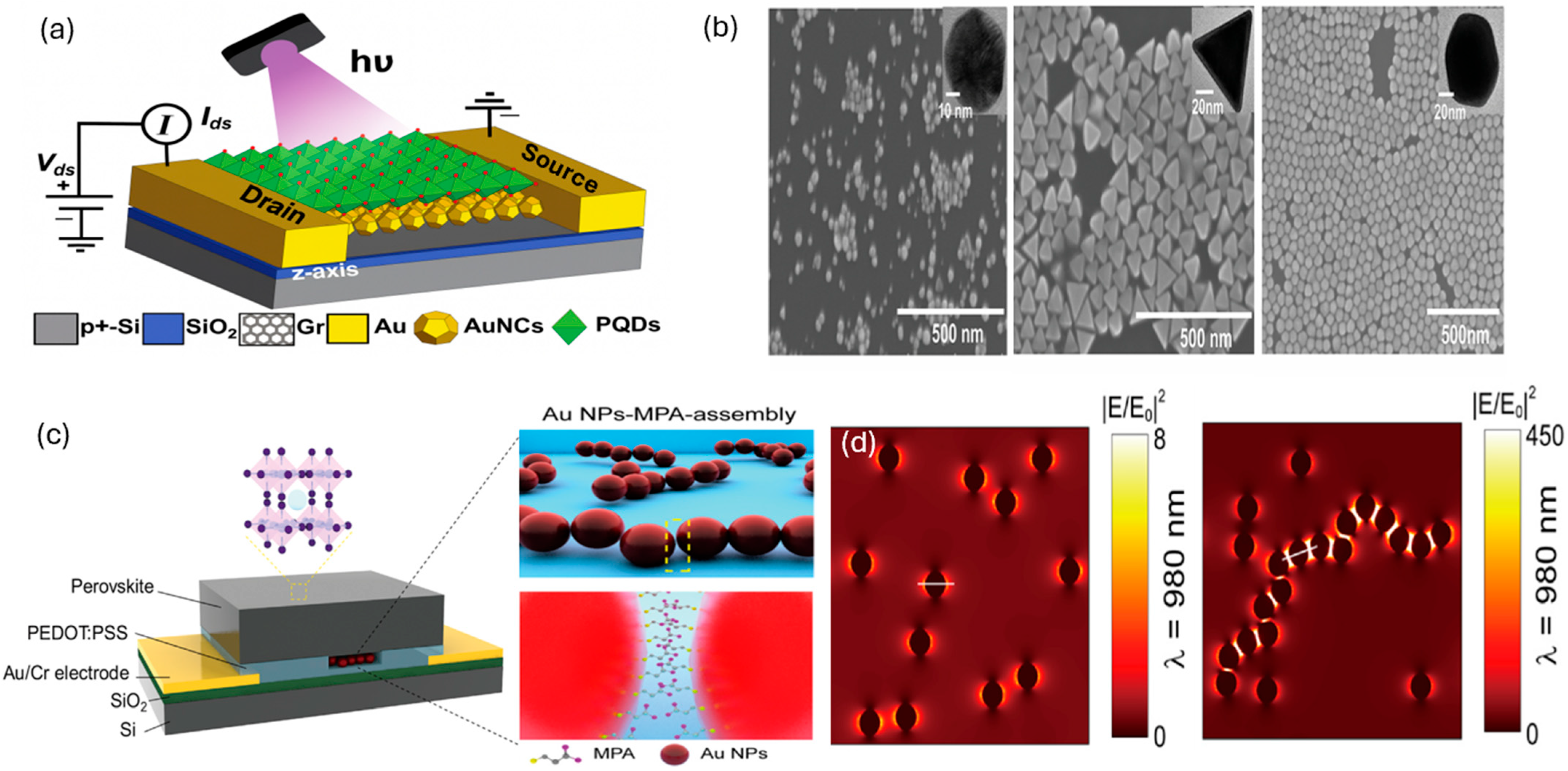
Perovskite quantum dots (PQDs) have also been employed in graphene/plasmonic NP hybrid Pe-PDs. Yadav et al. fabricated a device by depositing MAPbBr3 PQDs onto a graphene channel [78] (Figure 4a). In this architecture, PQDs acted as the photo-absorbing layer, generating electron–hole pairs upon illumination; the photogenerated electrons are transferred to graphene, while holes remain in the PQDs, thereby modulating the channel conductivity and inducing a photocurrent. The resulting PQDs/graphene hybrid Pe-PD exhibited a significant enhancement in photoresponse compared with pristine graphene detectors, achieving R of ~105 A W−1 and EQE exceeding 107% at 432 nm. Furthermore, the rise and decay times of the photocurrent were reduced from 12 s and 17 s (PQDs/Gr) to 8.9 s and 16 s (PQDs/RD-Au NCs/Gr), respectively, confirming the faster photoresponse. To investigate the plasmonic contribution depending on the shape of plasmonic NPs, three different morphologies of Au nanocrystals (Au NCs) (e.g., sphere, octahedron (OD), and rhombic dodecahedron (RD)) were incorporated into the PQDs/graphene hybrid structure (Figure 4b). For sphere-shaped Au NCs (∼27 nm), the LSPR peak appeared at 528 nm, resulting in increased absorption and PL intensity, though the enhancement in device performance was relatively modest due to limited local electric field strength. In contrast, OD Au NCs (∼45 nm) exhibited an LSPR peak at 541 nm and provided a larger scattering cross-section and stronger local electric field than spheres, thereby significantly improving both photocurrent and absorption. RD Au NCs (∼50 nm) with an LSPR peak at 544 nm demonstrated the strongest plasmonic effect, featuring the largest scattering cross-section and most intense local electric field among the three shapes. Incorporation of RD Au NCs led to a ~10-fold increase in photocurrent compared with the sphere-based device, yielding a maximum photocurrent of 88.2 μA, R of 2.7 × 10⁵ A W−1, D* of 4.9 × 10¹³ Jones, and EQE of 7.9 × 10⁷%.

4.3. Perovskite–Plasmonic Nanoparticle Assembly

A study by La et al. demonstrated the development of Pe-PDs with both high sensitivity and fast response speed by incorporating plasmonic Au NPs assembled into chain-like structures via 3-mercaptopropionic acid (MPA) [79] (Figure 4c). In this system, MPA serves as a bifunctional linker: its thiol group binds to the Au surface, while its carboxyl group bridges adjacent nanoparticles, thereby inducing ordered chain-like assemblies. Unlike randomly aggregated Au NPs, these MPA-induced assemblies maintain ~0.6 nm interparticle gaps, enabling strong plasmonic coupling, hot spot formation, and enhanced electromagnetic fields compared with isolated Au NPs. The Au NP assemblies were prepared using 3-mercaptopropionic acid (MPA), a short-chain alkanethiol, and embedded within the poly(3,4-ethylenedioxythiophene) polystyrene sulfonate (PEDOT–PSS) hole transport layer. Compared with devices containing only isolated Au NPs, the assembly structure induced plasmon coupling, creating narrow interparticle cavities, which generated strong field enhancement and improved charge extraction and transport simultaneously (Figure 4d). The Au NPs-MPA assembly-based Pe-PDs exhibited R of ~2063 A W−1, which is 4.1 times higher than that of the pristine device, noise equivalent power (NEP) of 1.93 × 10¹⁴ W Hz−1/2 corresponding to a 15.6-fold reduction, and maximum D* of 1.16 × 10¹² Jones. These enhancements were primarily attributed to three mechanisms: (i) the reduced hole injection barrier induced by Au NPs, leading to improved charge extraction efficiency; (ii) the strong electromagnetic fields generated within the NP chain structure, which facilitated charge separation and transport, thereby accelerating the response speed; and (iii) the excitation of gap plasmons and longitudinal modes, which extended the absorption spectrum from the visible to the near-infrared (NIR) region, contributing additional photocurrent generation. Furthermore, devices fabricated with shortened channel lengths achieved response times as fast as ~300 ns, reduced from ~850 ns in the longer channel devices, corresponding to a 2.8-fold improvement in photoresponse speed. These results demonstrate that embedding Au NPs-MPA assemblies into the PEDOT–PSS layer provides a highly effective strategy for achieving Pe-PDs with both ultrahigh sensitivity and rapid response.

4.4. Perovskite–Interlayer–Plasmonic Nanoparticle

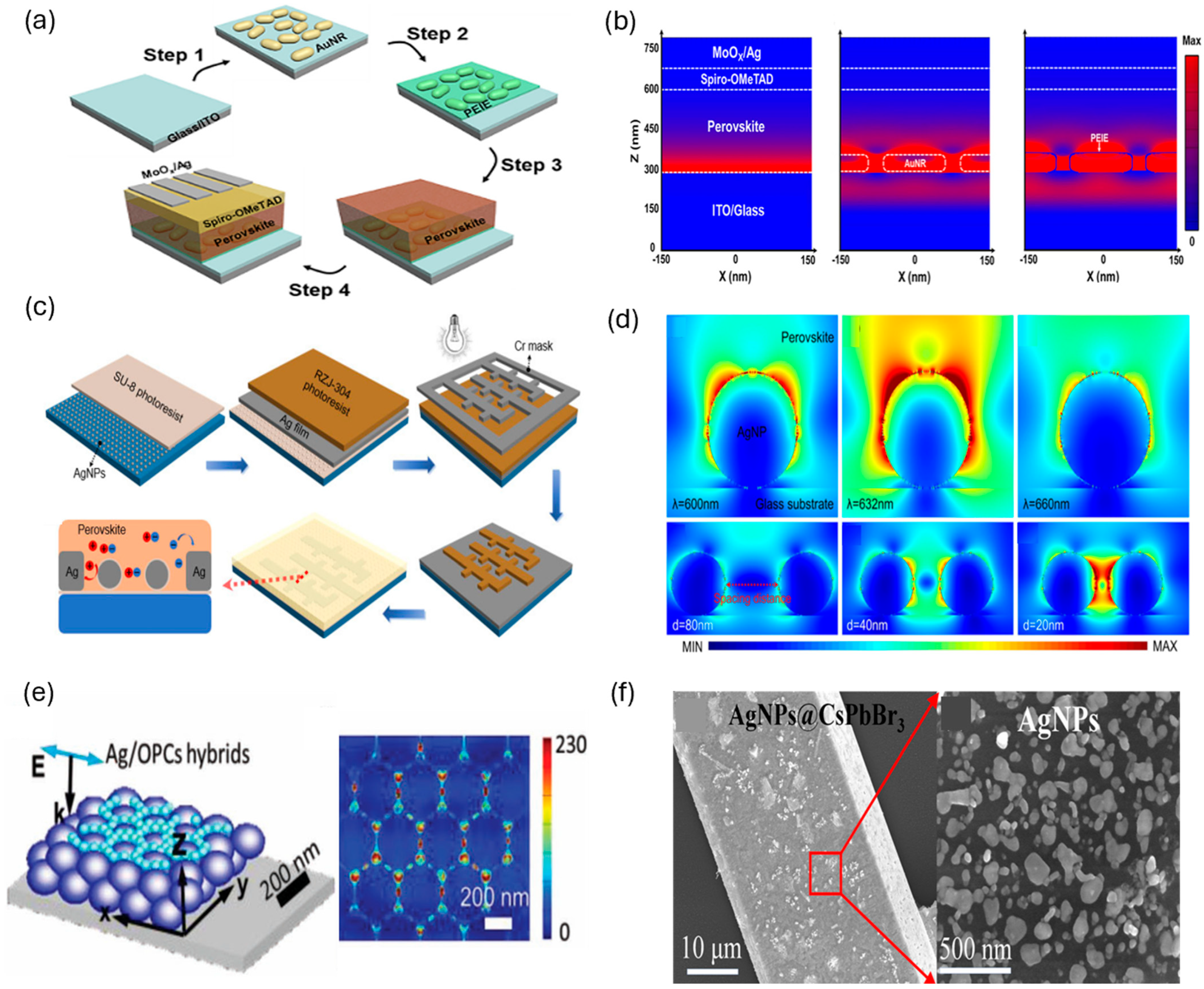
To mitigate the potential increase in dark current caused by the incorporation of plasmonic NPs, strategies involving the interfacial passivation layer into plasmonic nanostructures have also been reported. Lim et al. integrated Au nanorods (NRs) exhibiting LSPR into the ITO electrode to enhance the light absorption of MAPbI3-based Pe-PDs, while simultaneously inserting a thin polyethyleneimine ethoxylated (PEIE) interlayer (~7.9 nm) between the Au NRs and the perovskite active layer [80] (Figure 5a). PEIE, an amine-based cationic polymer, acts as an interfacial passivation layer by blocking electron injection through band alignment and suppressing interfacial trap states, thereby reducing dark current. Among the four fabricated devices (MAPbI3 control, with only Au NRs, with only PEIE, and with Au NRs/PEIE), the hybrid structure incorporating both Au NRs and PEIE exhibited the best photodetection performance. The device achieved R of 0.360 A W−1 and D* of 1.81 × 10¹⁰ Jones, representing a remarkable enhancement compared with the other devices. In addition, the dark current was significantly suppressed to 2.93 × 10⁻¹⁰ A, corresponding to a ~76% reduction relative to the pristine MAPbI3 control device (1.21 × 10⁻⁹ A). These improvements were attributed to the synergistic effects of plasmonic light amplification by Au NRs and interfacial stabilization by the PEIE interlayer (Figure 5b). PL and TRPL analyses revealed that Au NRs facilitated faster charge transfer and reduced recombination, while the PEIE interlayer prevented excessive quenching caused by direct contact between Au NRs and the perovskite, thereby improving charge transport efficiency. Furthermore, finite-difference time-domain (FDTD) simulations confirmed that the electromagnetic field enhancement and scattering effects induced by Au NRs contributed to increased light absorption, consistent with the observed performance improvement.
Another study reported the use of SU-8 encapsulation to reduce recombination losses while simultaneously leveraging the plasmonic enhancement provided by silver nanoparticles (Ag NPs). Ye et al. incorporated Ag NPs exhibiting LSPR together with an SU-8 photoresist encapsulation layer to enhance the performance of CH3NH3PbI3-based Pe-PDs [81] (Figure 5c). SU-8 effectively prevented the oxidation of Ag, suppressed Ag+ ion migration, and passivated surface trap states, thereby optimizing carrier transport. The device was fabricated by spin-coating Ag NPs onto a glass substrate coated with SU-8, forming microelectrodes, and subsequently depositing the perovskite active layer. The resulting Pe-PD showed the photocurrent enhancement from 0.19 μA to 0.86 μA, corresponding to a 352.6% enhancement. The R and EQE enhanced from 0.105 A W−1 to 0.478 A W−1, while the EQE improved from 0.206% to 0.940%. The D* was significantly enhanced from 1.11 × 10¹⁰ Jones to 5.04 × 10¹⁰ Jones (354% increase), and the linear dynamic range (LDR) expanded from 37.6 dB to 50.7 dB. Additionally, the response speed improved, with the rise and decay times reduced from 277/248 ms to 222/210 ms, respectively. These improvements were attributed to the strong electromagnetic field amplification induced by LSPR around Ag NPs (Figure 5d), which enlarged the light absorption cross-section within the perovskite layer, and to the SU-8 encapsulation layer, which suppressed defect-mediated recombination and enhanced crystallinity for more efficient charge transport. Furthermore, the device maintained stable performance even after 1000 on/off switching cycles, demonstrating device reliability. This work highlights that SU-8 encapsulated Ag NPs can provide a dual benefit of plasmonic enhancement and defect passivation, enabling significant performance improvements in Pe-PDs with simple device architectures.

4.5. Perovskite Photonic Crystal–Plasmonic Nanoparticle

Plasmonic NPs hybridized with photonic crystals have also been incorporated to further enhance the performance of Pe-PDs. Li et al. developed UV-sensitive Pe-PDs by hybridizing plasmonic Ag NPs with opal photonic crystals (OPCs) [82] (Figure 5e). They proposed a new strategy that couples plasmonic metals with photonic crystals, simultaneously exploiting the LSPR of a Ag NPs-based film and the photonic stop band (PSB) of polymethyl methacrylate (PMMA) OPCs. Ag concentrated incident light into a local electric field to amplify both excitation and emission processes, whereas OPCs control electromagnetic waves via periodic refractive-index modulation to strengthen emission. In particular, the Ag/OPCs hybrid structure exhibited a strong synergistic effect, resulting in an electric field enhancement of up to 230 times near the surface of CsPbCl3 nanocrystals, with the most pronounced enhancement observed when the CsPbCl3 layer thickness was ≤ 50 nm. Compared with pristine CsPbCl3, CsPbCl3 deposited on a Ag NPs-based film showed 50 times higher PL intensity; on OPCs it showed 20 times higher; and in the Ag/OPCs hybrid it reached up to 150 times, with an emission efficiency of 51.5%. The PL lifetime is shortened from 3.7 ns to 1.8 ns, evidencing an increased radiative rate, indicating that not only absorption but also emission-field and excitation-field enhancements contributed concurrently. Based on this platform, the resulting UV-sensitive Pe-PDs delivered excellent device performance: a very low dark current on the order of 10−11 A, D* of 9 × 10¹⁴ Jones, rise/decay times of 28/31 ms (40~50% reduction versus the control), and R of 8.1 A W−1 at 365 nm, exceeding the typical ~1.0 A W−1 of commercial UV detectors. The spectral response bandwidth is as narrow as 30 nm. Moreover, devices fabricated on PET substrates maintained high stability and performance under flexible operation.

4.6. Perovskite: Inorganic Heterojunction–Plasmonic Nanoparticle

In addition to Pe-PDs solely using a perovskite layer as an active layer, plasmonic Pe-PDs based on heterojunction systems with inorganic semiconductors have also been investigated. Lin et al. fabricated a heterojunction Pe-PD composed of a CsPbBr3 microwire and a p-GaN substrate, in which Ag NPs were introduced to induce LSPR and simultaneously passivate surface defects, thereby enhancing both device performance and stability [83] (Figure 5f). For the pristine CsPbBr3/GaN heterojunction device without Ag NPs, the R, D*, and EQE reached 11.6 A W−1, 6.3 × 10¹¹ Jones, and 3781%, respectively, with rise/decay times of 11.98/27.13 ms. Upon integration of Ag NPs, the device performance improved markedly, achieving R of 63.9 A W−1 (5.5 times enhancement), D* of 4.05 × 10¹² Jones (6 times enhancement), and EQE of 1.5 × 10⁴%, while the response speed was significantly accelerated to 1.0/21.3 ms. Moreover, stability tests demonstrated that while the pristine CsPbBr3/GaN device exhibited a substantial decrease in photocurrent after 60 days of storage in air, the Ag NPs-integrated device maintained nearly constant photocurrent, confirming a remarkable improvement in long-term stability.

5. Plasmonic Nanopattern-Based Pe-PDs

5.1. Perovskite–Plasmonic Nanopattern

To overcome the limited near-infrared (NIR) response of conventional Pe-PDs, Du et al. introduced Au nanosquare arrays [84]. They fabricated NIR perovskite PDs on a plasmonic functionalized multilayer substrate composed of Au film/SiO2 spacer/nanosquares arrays (Figure 6a). The plasmonic PD was constructed by sequentially depositing a 100 nm Au film and a 10 nm SiO2 dielectric layer onto a Si/SiO2 substrate via electron beam evaporation, followed by the fabrication of 50 nm Au source/drain electrodes and 30 nm Au nanosquare arrays using electron (E)-beam lithography. Subsequently, a 20 nm (2,3,5,6-tetrafluoro-7,7,8,8-tetracyanoquinodimethane (F4-TCNQ)-doped poly [bis(4-phenyl) (2,4,6-trimethylphenyl) amine] (PTAA) hole transporting layer and an 80 nm CH3NH3PbI3 layer were spin-coated on the plasmonic substrate. To investigate the optical properties of the perovskite film, the reflectance spectra and photoluminescence (PL) characteristics were measured. The perovskite film fabricated on the plasmonic substrate exhibited stronger reflectance than that on the Si/SiO2 substrate, especially in the near-infrared region from 750 to 850 nm, where a considerable absorption enhancement was observed. Moreover, the film on the plasmonic substrate exhibited approximately twice the PL intensity compared with the Si/SiO2 substrate, with the PL emission peak located around 765 nm (1.62 eV), indicating improved light absorption and enhanced optoelectronic coupling due to plasmonic effects. Furthermore, time-resolved PL measurements revealed that the perovskite film on the plasmonic substrate exhibited a significantly shortened PL lifetime (2.09 ns vs. 13.87 ns), suggesting faster charge transfer between the perovskite and the hole-transporting layer, thereby facilitating more efficient carrier injection into the electrodes. Device characterization revealed that at 800 nm, the plasmonic Pe-PDs achieved a maximum photocurrent of 4.6 nA, approximately nine times higher than that of the non-plasmonic device, and an EQE of 65%, representing a 2.5-fold enhancement. The enhancement of EQE was maximized at 800 nm, attributed to improved light harvesting via localized surface plasmon resonance (LSPR) absorption, which increased photocurrent generation. Furthermore, as the size of the Au nanosquares increased, the LSPR peak red shifted, demonstrating that tuning the nanosquare dimensions provides an effective strategy for controlling the spectral response of Pe-PDs.
Gu et al. developed plasmonic Pe-PDs with enhanced photodetection properties in the visible range by hybridizing Au triangular arrays with MAPbI3 perovskite [85]. The triangular Au arrays were fabricated by (E)-beam lithography, followed by Au electrode deposition, and then a MAPbI3 solution was spin-coated to construct the plasmonic Pe-PDs (Figure 6b). Plasmonic Pe-PDs showed higher Iph (photocurrent), confirming that the incorporation of Au arrays significantly enhanced the photocurrent generation. This photocurrent enhancement was attributed to the effective electron transfer between the Au arrays and the perovskite film, which suppressed the recombination of electron-hole pairs, and to the enhanced electric field induced by the LSPR effect, which facilitated the generation of more electron-hole pairs in the perovskite-Au system. The resulting Pe-PD exhibited EQE of 12.6%, 15.9%, and 16.9% at excitation wavelengths of 450 nm, 532 nm, and 635 nm, respectively, which were about three times higher than those of the pristine device at the same wavelengths.

5.2. Perovskite–AAO–Plasmonic Nanopattern

In addition to the noble metals Au and Ag, studies have also reported the use of non-noble metals such as Al and Cu to improve the performance of PQD-based PDs. Li et al. reported the fabrication of AAO porous structures via a two-step anodization process, followed by thermal evaporation of metallic sources and annealing to form metallic nanoparticles (Al, Ag, and Cu) on the surface, and subsequent spin coating of CsPbBr3 QD solution to construct plasmonic PDs [86] (Figure 6c). Among the various metals-based plasmonic Pe-PDs fabricated by this method, the Al/AAO hybrid plasmonic Pe-PDs exhibited the highest photodetection performance, with R of 4.8 mA/W at a bias of 1 V, which was 48 times higher than that of bare glass substrate-based pristine Pe-PDs, and the EQE was enhanced by about 40 times from 0.03% to 1.21%. The enhancement has been attributed to multiple interferences within the AAO matrix combined with strong plasmonic coupling among metallic NPs, resulting in spatial light confinement. Notably, the dense distribution of Al nanoparticles provides a stronger electromagnetic field compared with Ag or Cu, leading to superior PL intensity.

5.3. Perovskite–Plasmonic Multiple Pattern

Compared to a single nanograting or nanoparticle (NP), the use of multiple plasmonic patterns significantly enhances light amplification. This approach overcomes the limitation of single nanogratings, where strong light amplification only occurs when the polarization of the incident light is nearly perpendicular to the grating due to its unidirectional structure. Lee et al. developed high-performance flexible Pe-PDs by applying high-efficiency hierarchical plasmonic nanostructures composed of cross-nanograting patterns (CGs) and nanoposts (NPs) [63]. The hierarchical cross-nanogratings with NPs (CN) patterns were fabricated by combining block copolymer lithography with nanoimprint lithography. A PS-b-PMMA film was spin-coated on a Si/SiO2 substrate and annealed, followed by nanoimprinting using a poly(dimethylsiloxane) PDMS stamp with CG patterns. Subsequently, UV/acid treatment was carried out to remove PMMA and form nanoholes, which were then used as a mask for dry etching to produce CN-patterned SiO2 films. Using these SiO2 films as masters, CN-patterned PDMS stamps were prepared, and Au was deposited on the CN-patterned PS films to complete plasmonic CN-patterned Au films (Figure 6d). The CN patterns induced LSPR, exhibiting superior light trapping performance by concentrating on the electromagnetic field. Under red light illumination (10 μW/cm2). The R increased from 140.5 mA/W for flat Pe-PDs to 588.6 mA/W for CN-based Pe-PDs, corresponding to an approximately 4.2-fold enhancement. The EQE improved from 26% to 109%, and the D* increased from 6.5 × 10¹¹ to 22.5 × 10¹¹ Jones, representing about 4.2-fold and 9.9-fold enhancements, respectively. Particularly, in the 450–670 nm range, the CN-based devices outperformed other single plasmonic structures (GN, CG, and grating). In addition, stable photoresponse characteristics were maintained under a minimum bending radius of 8 mm and after more than 1000 repeated bending cycles, demonstrating both mechanical flexibility and operational stability.
A study has demonstrated that the integration of metasurfaces and nanopatterns can induce stronger plasmonic effects, including SPP resonances and enhanced local thermoelectric fields. These phenomena significantly boost photothermal conversion within the perovskite layer and enhance the photothermoelectric (PTE) effect, thereby overcoming the inherent bandwidth limitations of perovskite-based polarization detectors, which were previously confined to the visible–near-infrared range. Li et al. developed a PD that utilizes the PTE effect [87]. The device was composed of a multilayer structure: Cs0.05(FA0.85MA0.15)0.95Pb(I0.85Br0.15)3 (CsFAMA) perovskite layer, PEDOT: PSS layer, and metasurface. To optimize the device’s structure, the researchers used CST Microwave Studio simulations to compare two types of metasurfaces: T-shaped and I-shaped designs (Figure 6e). The I-shaped metasurface demonstrated superior performance due to stronger boundary effects and enhanced SPP resonance. Under 0.1 THz irradiation, the I-shaped device achieved a high R of 94 V W−1, a low NEP of 5.03 pW Hz−1/2, and a fast response time of 138 µs. It also generated a maximum photovoltage of 5.1 mV and a minimum of 3.7 mV, resulting in an anisotropy ratio of 1.38. Even after 240 days of storage in ambient air, the device maintained excellent stability, with the polarization ratio changing by less than 2%. In comparison, the T-shaped metasurface recorded an anisotropy ratio of 1.22, with maximum and minimum photovoltages of 3.4 mV and 2.8 mV, respectively. For a control device without metasurface structures, simulations showed that the maximum electric field intensity reached only 1 kV/m. In contrast, the inclusion of metasurface structures increased this value significantly to 4 kV/m, demonstrating the effectiveness of the metasurface design in enhancing device performance.

5.4. Plasmonic Hot Carrier Inducing Structure

Upon photoexcitation in pristine perovskite materials, both electrons and holes are generated in perovskite materials. Hot carriers are those that possess excess kinetic energy significantly above the thermal equilibrium at ambient temperatures [88]. The generation and distribution of these hot carriers depend on the electronic band structure of the perovskite and the energy of the incident photons. However, due to ultrafast carrier relaxation processes [89,90], only a small fraction of the initially excited hot carriers can be extracted before thermalization occurs [91]. On the other hand, in plasmonic-enhanced perovskite structures, LSPRs in metallic nanostructures play a critical role in facilitating hot carrier generation [92,93]. When these nanostructures absorb light, the decay of excited plasmons can transfer energy to nearby electrons, elevating them to high-energy (hot) states within the conduction band. These hot electrons can be injected into adjacent perovskite layers or other semiconductor components, depending on the device architecture and interface engineering [94]. This process can significantly increase the light-harvesting capability of the system, thereby potentially improving the performance of Pe-PDs [70,85,95]. In addition to the light-harvesting capability, in the field of perovskite solar cells, studies have shown that hot carriers injected from plasmonic nanostructures can effectively fill trap states in the charge transport layers adjacent to the perovskite absorber [96,97]. This effect can reduce the interfacial traps or increase the free carrier density in materials such as TiOx, thereby enhancing their electrical conductivity and carrier mobility. Furthermore, the efficient transfer of hot excitation supports the idea that hybrid architectures combining metals and perovskite semiconductors are promising platforms for developing highly efficient plasmon-induced and plasmon-enhanced light emission from semiconductors [67].
A study has also reported the enhancement of Pe-PDs performance by utilizing hot electrons generated through plasmonic effects. Park et al. fabricated a plasmonic nanodiode incorporating MAPbI3 perovskite and proposed a structure that improves both the generation and the lifetime of hot electrons [66]. The device consisted of a MAPbI3 layer coated on TiO2 substrates decorated with plasmonic Au nanoislands, forming a MAPbI3/plasmonic Au/TiO2 Schottky nanodiode (Figure 6f). The MAPbI3/plasmonic Au/TiO2 nanodiode exhibited distinct incident photon-to-electron conversion efficiency (IPCE) enhancements at 1.6 eV, 2.2 eV, and 2.5 eV. The enhancement at 1.6 eV originated from the direct p-n junction formed between MAPbI3 and TiO2, where electrons excited at the conduction band edge of MAPbI3 were extracted. At 2.2 eV, strong LSPR effects generated additional secondary hot electrons, thereby increasing the IPCE. The enhancement above 2.5 eV was attributed to hot electron extraction from the MAPb3 film itself. In terms of photocurrent, the Au/TiO2 structure generated 25 nA, which increased to 128 nA after introducing plasmonic Au nanoislands. With the subsequent incorporation of the MAPbI3 film, the photocurrent further increased from 139 nA to 552 nA. This improvement arises from the efficient extraction of hot electrons generated within the plasmonic Au via the formation of a three-dimensional Schottky interface, combined with the additional hot electron flux generated in the MAPbI3 film. The MAPbI3 structure, coupled with LSPR, exhibited higher IPCE values across most photon energy regions compared with non-plasmonic structures. At photon energies above 2.7 eV, the MAPbI3/plasmonic Au/TiO2 nanodiode showed significantly higher IPCE, attributed to the near-field enhancement induced by Au nanostructures. This effect allowed MAPbI3 near the plasmonic Au regions to absorb light more efficiently and generate an increased number of hot electron–hole pairs. Furthermore, since hot electrons are generated close to the hot spots of plasmonic Au, their extraction in the MAPbI3/plasmonic Au structure was much more efficient compared with MAPbI3/thin Au structures. Consequently, MAPbI3 integrated with LSPR active plasmonic Au exhibited superior IPCE and short circuit photocurrent values relative to non-plasmonic MAPbI3 devices.

5.5. Plasmonic-Photonic Hybrid Structure
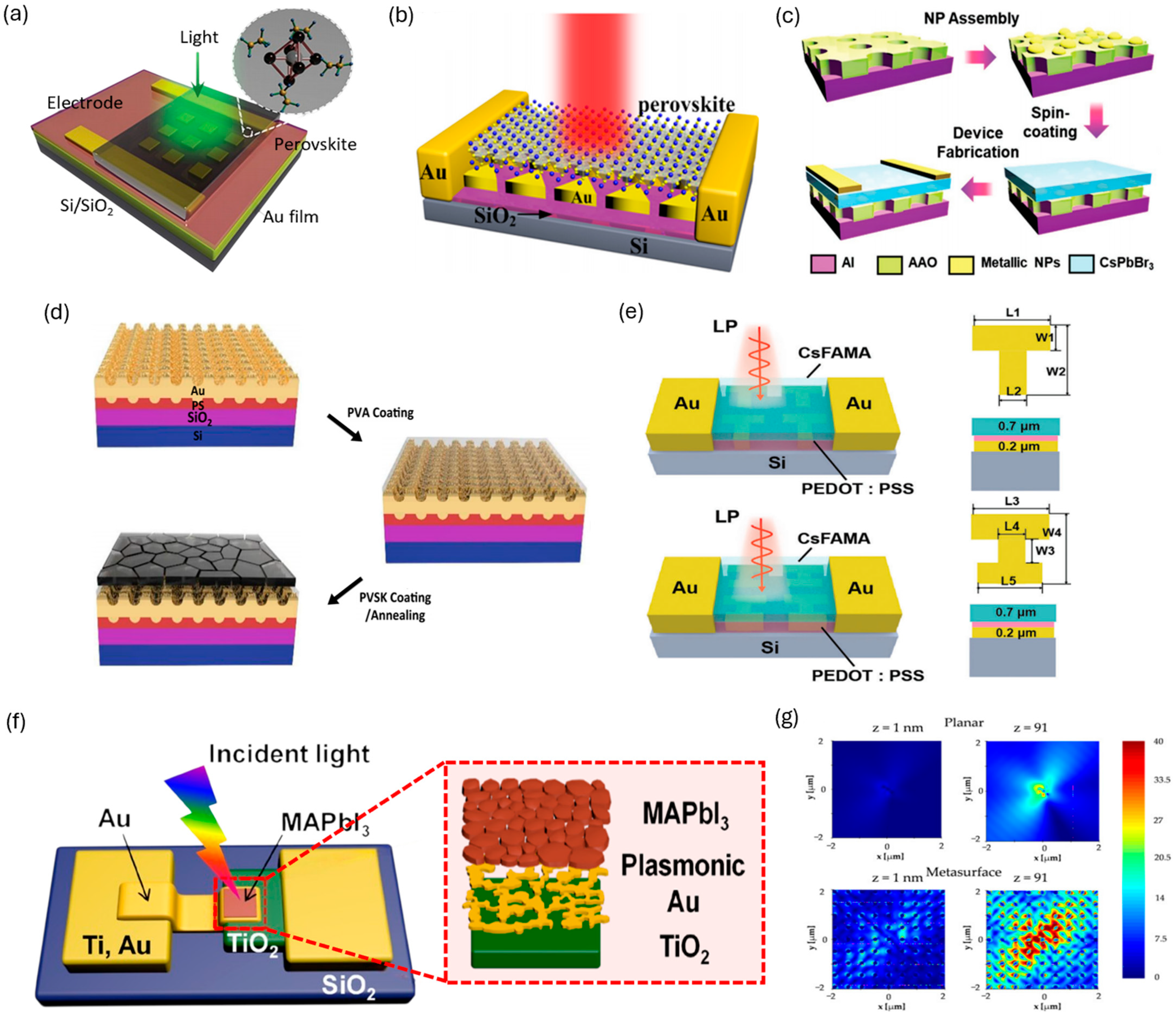
Kowal et al. proposed a novel plasmonic-photonic hybrid structure based on hybrid plasmonic-photonic modes, providing a pathway to overcome the limitations of conventional plasmonic Schottky junction PDs [98]. The structure consists of a metasurface incorporating Ag nanopillars integrated with a perovskite film, designed and analyzed using the finite-difference time-domain (FDTD) method. The designed hybrid system exhibited up to a fivefold enhancement of optical field intensity within a 4 × 4 μm pixel unit compared with flat junctions, along with pronounced light-trapping performance in the near-infrared regime, around 300 THz (≈1000 nm). Importantly, the coupling between the guided Bloch mode and the surface lattice resonance (SLR) resulted in strong electromagnetic field confinement at the metal/perovskite interface (Figure 6g), which was identified as a key factor in enhancing photogeneration efficiency. Moreover, the proposed architecture supports both passive and active photodetection, enabling multispectral and multilayer device designs, and offers efficient operation even in relatively thick film configurations. Although the study remains at the simulation stage, this hybrid plasmonic-photonic approach is considered a promising platform for future extension toward infrared, ultraviolet, and X-ray detection.
Figure 6. (a) Schematic of the device on the plasmonic substrate [84]. Copyright © 2018 Wiley. (b) Schematic illustration of the MAPbI3-Au-based PD [85]. Copyright © 2020 Elsevier Ltd. (c) Schematic fabrication of hybrid plasmonic nanostructure-based Pe-PDs [86]. © 2020 Wiley. (d) Schematic diagram of fabrication process of PVA and MAPbI3 perovskite films on a GN-patterned Au layer [63]. Copyright © 2024 Wiley. (e) Schematic diagram of T-shaped and I-shaped PDs structures and dimensions, respectively [87]. Copyright © 2024 Wiley. (f) Schematic of the MAPbI3/plasmonic-Au/TiO2 nanodiode (left) and magnified illustration of the active area (right) [66]. Copyright © 2019 American Chemical Society. (g) Comparison of the electric field magnitude |E| simulated in the planar (top) and structured (bottom) junction configurations at the vertical coordinate z = 1 nm, which corresponded to the metal patch, and z = 91 nm, which corresponded to the top of the pillars [98].
Inorganics 13 00351 g006

6. Chiral Plasmonics in Perovskites

6.1. Chiral Plasmonic Nanoparticles

Beyond conventional optoelectronic devices that typically respond to unpolarized light, introducing chirality or chiral plasmonic structures into perovskite materials paves the way for a new generation of technologies [42]. This convergence has led to the observation of a wide range of intriguing phenomena, including circular dichroism (CD), circularly polarized photoluminescence (CPPL), nonlinear optical responses, the chiral-induced spin selectivity (CISS) effect, and spintronic behavior [99,100]. These findings underscore how the synergy between the intrinsic advantages of perovskites and the distinctive nature of chirality is deepening our understanding of this rapidly evolving field in optoelectronics. Chiral optoelectronics provides promising applications such as enantioselective sensing [101], polarization-sensitive imaging [102], and advanced systems for quantum-secure communication and data transmission [103]. As a result, there is increasing focus on the design and development of chiral optical nanostructures by using perovskite materials, leading to enhancement of chiral responses such as CD and CPPL [104,105,106,107,108,109,110].
Seo et al. reported a significant enhancement in CPPL at room temperature by leveraging chiral Fano resonances, highlighting the potential of perovskite-based structures for efficient circularly polarized light (CPL) emission [104]. In their approach, triangular silver nanopatterns (with side lengths ranging from 370 to 430 nm) were fabricated on a quartz substrate using E-beam lithography. These nanostructures were then coated with a thin Al2O3 insulating layer, followed by the deposition of a ~210 nm-thick MAPbI3 perovskite film via spin-coating (Figure 7a,b). Optical measurements of the resulting structure revealed characteristic Fano resonances, marked by asymmetric spectral features. These arose from the interplay between the broad Fabry–Perot resonance of the perovskite layer and narrow quasi-guided modes induced by the periodic nanopatterns. This interference gave rise to chiral Fano resonances within the perovskite film, resulting in a substantial amplification of CPPL (Figure 7c).

6.2. Chiral Metasurfaces

Aside from conventional plasmonic structures based on metals, significant research efforts have focused on creating chiral metasurfaces by engineering perovskite materials themselves into specific geometries [105,106]. These intrinsically chiral perovskite metasurfaces can offer valuable insight into the design principles for imparting chirality to future plasmonic nanostructures for perovskite optoelectronics. For example, Long et al. successfully created large-area, CPL-active 2D-chiral perovskite metasurfaces by employing a template-assisted self-assembly technique with halide perovskite NCs and pre-patterned elastomeric stamps [105] (Figure 7d). These chiral nanostructures were produced by depositing perovskite NC inks onto glass substrates, then pressing them with one of three distinct PDMS molds featuring 500 nm gammadion-shaped patterns arranged in a square lattice with a 600 nm pitch. The molds created left-handed (L), right-handed (R), and racemic (O) configurations across 9 mm2 patterned regions. Unlike three-dimensional chiral forms such as helices, these gammadion patterns exhibit two-dimensional chirality; their handedness appears reversed when viewed from opposite sides (Figure 7e,f). This phenomenon is supported by chiral near-field distributions of opposite handedness on each side under illumination. The resulting 2D perovskite metasurfaces demonstrated impressive photoluminescence dissymmetry factors (glum, 2(ILCPIRCP)/(ILCP + IRCP); ILCP and IRCP are the intensities of the left- and right-circularly polarized PL) around 0.16, which could be further enhanced to 0.3 by applying a coating with a high refractive index.
Another approach to forming chiral metasurface involves combining perovskite materials with high-refractive-index titanium dioxide (TiO2), enabling strong light–matter interactions. Fiuza-Maneiro et al. demonstrated strong chiral light emission from inherently achiral CsPbBr3 nanocrystals by simply depositing them onto pre-formed chiral metasurfaces [106]. The metasurfaces were fabricated using nanoimprint lithography (Figure 7g). A thin 100 nm layer of photoresist was first patterned through hot embossing onto oxygen plasma-treated glass substrates. The embossing mold, made from PDMS, featured a square array of gammadion structures with 600 nm periodicity and 500 nm lateral dimensions, covering a 9 mm2 area. Three types of metasurfaces were prepared: left-handed (L), right-handed (R), and racemic (O) orientations. To enhance light–matter interactions, a high-refractive-index TiO2 layer (n = 2.4) was used. Finally, the perovskite nanocrystals were spin-coated directly onto the chiral metasurfaces. This straightforward integration yielded chiral optical systems exhibiting notable glum values of up to 0.56. The metasurfaces enabled broadband CPPL across the visible spectrum, achieved through resonant coupling between the chiral structures and the emission of both green and red perovskite nanocrystals (Figure 7h).
Although much of the earlier work emphasized the enhancement of chiral photoluminescence using metasurfaces, Long et al. shifted focus toward investigating how such chiral nanostructures influence asymmetric light absorption [107]. In their study, planar gammadion-shaped chiral perovskite metasurfaces, each with opposite handedness, were directly patterned onto MAPbI3 films using focused ion beam (FIB) milling (Figure 7i). The fabricated metasurfaces exhibited pronounced chiroptical responses, achieving CD of 6350 millidegrees and an anisotropy factor for absorption (gabs) of 0.49 (Figure 7j). Simulations further predicted that expanding the metasurface area could push the anisotropy factor to 1.11 and CD values to around 18,900 millidegrees, which approached to the theoretical maximum.

6.3. Chiral Structures in Perovskites Optoelectronics

The integration of chiral plasmonic nanostructures into practical optoelectronic devices (especially for Pe-PDs) has remained limited while a recent study demonstrated enhanced asymmetric light emission in the perovskite-based light-emitting device using chiral metasurfaces. An effort has been made to incorporate chiral metasurface into practical perovskite-based light-emitting devices, providing experimental evidence that these structures can be effectively integrated into practical devices and suggesting their potential applicability in future Pe-PD designs. Kim et al. introduced an interesting concept of chiral light emission using a perovskite-based thin-film metacavity and successfully demonstrated chiral electroluminescence (EL) experimentally [108] (Figure 7k). The device architecture consisted of a CsPbBr3 perovskite emission layer sandwiched between a metallic back reflector and a specially engineered metamirror composed of a square array of triangular polycrystalline silicon (poly-Si) elements (Figure 7l). The metamirror served a dual optical function: it acts as a partially reflective mirror supporting Fabry–Pérot resonances that selectively emit one handedness of circular polarization, while simultaneously suppressing modes of the opposite handedness. This polarization selectivity originated from the intrinsic ability of the metamirror to interact asymmetrically with circularly polarized light. The resulting chiral cavity modes enabled directional, asymmetric EL, producing left- and right-handed circularly polarized emissions that propagate at distinct oblique angles. The device achieved a notable peak circular polarization degree of approximately 0.38.
Following the study on EL based on chiral plasmonic structures, an effort has also been made to integrate chiral plasmonics into CPL Pe-PDs, enhancing their sensitivity and selectivity. Kim et al. developed CPL Pe-PDs incorporating chiral Au NPs into narrow-bandgap tin–lead mixed perovskites [109] (Figure 7m). By embedding chiral Au NPs within a Cs0.05FA0.5MA0.45Pb0.5Sn0.5I3 perovskite matrix, the resulting photodiode-type device achieved direct CPL detection in the near-infrared (NIR) region (Figure 7n). The optical activity of the chiral Au NPs could be finely controlled by tuning the refractive index of the surrounding environment, due to changes in their dielectric properties. Notably, the spectral overlap between the plasmonic resonance of chiral Au NPs and the absorption profile of the perovskite enabled efficient CPL discrimination in the NIR range. The resulting CPL Pe-PD exhibited a high photocurrent dissymmetry factor (gPh, 2(ILCPIRCP)/(ILCP + IRCP); ILCP and IRCP are the photocurrents generated under LCP and RCP illumination) of 0.55 even without external bias.
Recent advances in chiral plasmonics with perovskite materials have shown that incorporating chiral plasmonic structures can substantially enhance the asymmetric optical properties of perovskites. However, despite this promising potential, their integration into practical perovskite-based optoelectronic devices still remains limited. Further research is needed to fully harness the capabilities of chiral plasmonics in real-world applications.

7. Conclusions

In summary, Table 1 presents a comprehensive overview of the performance of plasmonic nanostructure-integrated Pe-PDs. Pe-PDs have rapidly advanced owing to the unique optoelectronic properties of perovskite semiconductors and the versatile opportunities offered by solution-based processing. In particular, the integration of plasmonic nanostructures has recently emerged as a powerful strategy to overcome the intrinsic performance limitations of Pe-PDs, enabling enhanced light absorption, faster carrier dynamics, and improved spectral selectivity. These advances highlight the critical role of plasmonics in bridging the gap between fundamental perovskite research and practical device applications.
At the same time, achieving real commercialization of Pe-PDs requires progress on several parallel fronts, including large-area processability, long-term operational stability, and the development of non-toxic lead-free perovskite alternatives. Beyond the development of perovskite material and manufacturing process, the next crucial step lies in incorporating plasmonic effects into Pe-PDs. Conventional studies on plasmonic Pe-PDs rely on noble metals such as Au and Ag, but their high cost, despite excellent optical properties, limits their viability for industrial adoption. Indeed, the high material cost has driven the semiconductor and display industries to instead rely on cost-effective scattering media, such as TiO2 particles, to achieve comparable light management.
In the pursuit of environmentally friendly and stable Pe-PDs, lead-free alternatives have garnered increasing attention [111,112]. Among them, Sn-based perovskites are particularly promising due to their suitable bandgaps, high carrier mobilities, and extended spectral response into the near-infrared region, with demonstrated potential in plasmonic PD applications [113]. However, challenges related to Sn2⁺ oxidation and rapid crystallization still hinder their stability and film quality. Bi-based and double perovskites (e.g., Ag2Bil5, Cs2AgBiBr6) also offer excellent long-term stability and decent photodetection capabilities [114,115], particularly in the UV–visible range. With the integration of plasmonic structures, their response can be extended into the NIR region [116]. Nonetheless, their performance still lags behind Pb- and Sn-based counterparts. Additionally, emerging systems based on Sb, Cu, and Ge show unique optoelectronic properties and potential for high-temperature operation [117,118,119,120], yet remain underexplored. Overall, while lead-free perovskites offer environmental and stability advantages, further material development, device engineering, and integration of plasmonic structures are essential to match or exceed the performance of traditional lead-based Pe-PDs.
Although the integration of plasmonic nanostructures has shown great promise in enhancing the performance of Pe-PDs, challenges related to scalability and cost-effective manufacturing of plasmonic nanostructures continue to hinder their commercial viability. To overcome these challenges, several scalable fabrication methods have been explored, including wrinkle-assisted colloidal particle assembly [121], bottom-up fabrication using spin-coating techniques [122,123], laser raster patterning [124], roll-to-roll nanoimprint lithography technique [125], AAO-assisted metal patterning [126], dip-coating [127], thermal oxidation of titanium foil followed by silver nanoparticle deposition [128], glancing angle deposition [129], chemical lift-off lithography [130], dynamic shadowing growth [131], and laser inference lithography combined with template-assisted self-assembly [132]. Nonetheless, designing nanostructures with controlled plasmonic effects over large areas is technically still demanding and requires high precision. Moreover, the practical application of scalable fabrication methods of plasmonic nanostructures to PDs with stacked complex structures remains rare. Therefore, developing plasmonic fabrication techniques that are compatible with multilayer device architectures is a critical challenge that must be addressed in the future.
Another key limitation to the large-scale application of plasmonic nanostructures is the high cost and limited availability of noble metals like gold and silver [133]. Although they offer strong plasmonic responses and chemical stability, their narrow operating wavelength range and high price hinder industrial-scale deployment. In contrast, earth-abundant, low-cost metals such as aluminum [134,135], palladium [136], and copper present promising alternatives [137,138], offering broader plasmonic bands suitable for efficient, broadband light harvesting. Thus, to enable sustainable and scalable plasmonic applications, there is a growing need to explore non-noble metal alternatives.
In the future, economically competitive plasmonic Pe-PDs may be realized through the exploration of alternative cost-effective plasmonic materials such as Al, Pd, and organic conductor materials [139,140,141]. The combined progress in scalable perovskite processing, eco-friendly compositions, and low-cost plasmonic designs will accelerate the transition from laboratory prototypes to practical optoelectronic products, ensuring that plasmonic Pe-PDs become embedded in everyday life.

Author Contributions

Y.H.L. proposed the topic of the review and supervised the writing. H.K., J.L., and C.B.L. equally contributed to writing the main sections. All authors have read and agreed to the published version of the manuscript.

Funding

This work was also supported by the National Research Foundation of Korea (NRF) grant (RS-2025-24533931, RS-2024-00340299) through the NRF by the Ministry of Science and ICT (MSIT), Korea.

Institutional Review Board Statement

Not applicable.

Informed Consent Statement

Not applicable.

Data Availability Statement

The original contributions presented in this study are included in the article. Further inquiries can be directed to the corresponding author.

Conflicts of Interest

The authors declare no conflicts of interest.

References

  1. Mitzi, D.B. Introduction: Perovskites. Chem. Rev. 2019, 119, 3033–3035. [Google Scholar] [CrossRef]
  2. Jena, A.K.; Kulkarni, A.; Miyasaka, T. Halide Perovskite Photovoltaics: Background, Status, and Future Prospects. Chem. Rev. 2019, 119, 3036–3103. [Google Scholar] [CrossRef]
  3. Manser, J.S.; Christians, J.A.; Kamat, P.V. Intriguing Optoelectronic Properties of Metal Halide Perovskites. Chem. Rev. 2016, 116, 12956–13008. [Google Scholar] [CrossRef]
  4. Zhao, Y.; Zhu, K. Organic–inorganic hybrid lead halide perovskites for optoelectronic and electronic applications. Chem. Soc. Rev. 2016, 45, 655–689. [Google Scholar] [CrossRef]
  5. Rogalski, A.; Wang, F.; Wang, J.; Martyniuk, P.; Hu, W. The Perovskite Optoelectronic Devices—A Look at the Future. Small Methods 2025, 9, 2400709. [Google Scholar] [CrossRef]
  6. Stranks, S.D.; Eperon, G.E.; Grancini, G.; Menelaou, C.; Alcocer, M.J.P.; Leijtens, T.; Herz, L.M.; Petrozza, A.; Snaith, H.J. Electron-Hole Diffusion Lengths Exceeding 1 Micrometer in an Organometal Trihalide Perovskite Absorber. Science 2013, 342, 341–344. [Google Scholar] [CrossRef]
  7. Chen, B.; Baek, S.-W.; Hou, Y.; Aydin, E.; De Bastiani, M.; Scheffel, B.; Proppe, A.; Huang, Z.; Wei, M.; Wang, Y.-K.; et al. Enhanced optical path and electron diffusion length enable high-efficiency perovskite tandems. Nat. Commun. 2020, 11, 1257. [Google Scholar] [CrossRef] [PubMed]
  8. Wang, P.; Wu, Y.; Cai, B.; Ma, Q.; Zheng, X.; Zhang, W.-H. Solution-Processable Perovskite Solar Cells toward Commercialization: Progress and Challenges. Adv. Funct. Mater. 2019, 29, 1807661. [Google Scholar] [CrossRef]
  9. Saki, Z.; Byranvand, M.M.; Taghavinia, N.; Kedia, M.; Saliba, M. Solution-processed perovskite thin-films: The journey from lab- to large-scale solar cells. Energy Environ. Sci. 2021, 14, 5690–5722. [Google Scholar] [CrossRef]
  10. Samiee, M.; Konduri, S.; Ganapathy, B.; Kottokkaran, R.; Abbas, H.A.; Kitahara, A.; Joshi, P.; Zhang, L.; Noack, M.; Dalal, V. Defect density and dielectric constant in perovskite solar cells. Appl. Phys. Lett. 2014, 105, 153502. [Google Scholar] [CrossRef]
  11. Kim, H.; Figueroa Morales, C.A.; Seong, S.; Hu, Z.; Muyanja, N.; Penukula, S.; Zheng, T.; Pizzo, Z.; Yim, C.S.; Lenert, A.; et al. Molecular design of defect passivators for thermally stable metal-halide perovskite films. Matter 2024, 7, 539–549. [Google Scholar] [CrossRef]
  12. Docampo, P.; Bein, T. A Long-Term View on Perovskite Optoelectronics. Acc. Chem. Res. 2016, 49, 339–346. [Google Scholar] [CrossRef] [PubMed]
  13. Zhao, R.; Gu, Z.; Li, P.; Zhang, Y.; Song, Y. Flexible and Wearable Optoelectronic Devices Based on Perovskites. Adv. Mater. Technol. 2022, 7, 2101124. [Google Scholar] [CrossRef]
  14. Kim, H.; Lee, J.W.; Han, G.R.; Kim, Y.J.; Kim, S.H.; Kim, S.K.; Kwak, S.K.; Oh, J.H. Highly Efficient Hole Transport Layer-Free Low Bandgap Mixed Pb–Sn Perovskite Solar Cells Enabled by a Binary Additive System. Adv. Funct. Mater. 2022, 32, 2110069. [Google Scholar] [CrossRef]
  15. Lee, Y.H.; Tang, Y.; Dani, R.; Lee, W.-J.; Kim, J.H.; Lee, G.; Sun, J.; Ma, K.; Jeong, S.H.; Xu, W.; et al. Self-Aligned Fluorinated-Organic Ligand for Boosting the Performance of Perovskite Solar Cells. ACS Appl. Mater. Interfaces 2025, 17, 26751–26758. [Google Scholar] [CrossRef] [PubMed]
  16. Yang, S.J.; Lee, Y.H.; Tateno, K.; Dou, L. Elemental segregation and dimensional separation in halide perovskite light-emitting diodes. Prog. Quantum Electron. 2024, 98, 100537. [Google Scholar] [CrossRef]
  17. Brenner, T.M.; Egger, D.A.; Kronik, L.; Hodes, G.; Cahen, D. Hybrid organic—Inorganic perovskites: Low-cost semiconductors with intriguing charge-transport properties. Nat. Rev. Mater. 2016, 1, 15007. [Google Scholar] [CrossRef]
  18. Velilla, E.; Ramirez, D.; Uribe, J.-I.; Montoya, J.F.; Jaramillo, F. Outdoor performance of perovskite solar technology: Silicon comparison and competitive advantages at different irradiances. Sol. Energy Mater. Sol. Cells 2019, 191, 15–20. [Google Scholar] [CrossRef]
  19. Saif, O.M.; Zekry, A.H.; Abouelatta, M.; Shaker, A. A Comprehensive Review of Tandem Solar Cells Integrated on Silicon Substrate: III/V vs Perovskite. Silicon 2023, 15, 6329–6347. [Google Scholar] [CrossRef]
  20. Cai, S.; Xu, X.; Yang, W.; Chen, J.; Fang, X. Materials and Designs for Wearable Photodetectors. Adv. Mater. 2019, 31, 1808138. [Google Scholar] [CrossRef]
  21. Chow, P.C.Y.; Someya, T. Organic Photodetectors for Next-Generation Wearable Electronics. Adv. Mater. 2020, 32, 1902045. [Google Scholar] [CrossRef]
  22. Hao, D.; Zou, J.; Huang, J. Recent developments in flexible photodetectors based on metal halide perovskite. InfoMat 2020, 2, 139–169. [Google Scholar] [CrossRef]
  23. Kim, H.; Seong, S.; Gong, X. Heterostructure Engineering of Solution-Processable Semiconductors for Wearable Optoelectronics. ACS Appl. Electron. Mater. 2023, 5, 5278–5290. [Google Scholar] [CrossRef]
  24. Lee, Y.H.; Song, I.; Kim, S.H.; Park, J.H.; Park, S.O.; Lee, J.H.; Won, Y.; Cho, K.; Kwak, S.K.; Oh, J.H. Perovskite Granular Wire Photodetectors with Ultrahigh Photodetectivity. Adv. Mater. 2020, 32, 2002357. [Google Scholar] [CrossRef]
  25. Lee, Y.H.; Lee, W.-J.; Lee, G.S.; Park, J.Y.; Yuan, B.; Won, Y.; Mun, J.; Yang, H.; Baek, S.-D.; Lee, H.; et al. Large-Scale 2D Perovskite Nanocrystals Photodetector Array via Ultrasonic Spray Synthesis. Adv. Mater. 2025, 37, 2417761. [Google Scholar] [CrossRef]
  26. Lee, Y.H.; Park, J.Y.; Niu, P.; Yang, H.; Sun, D.; Huang, L.; Mei, J.; Dou, L. One-Step Solution Patterning for Two-Dimensional Perovskite Nanoplate Arrays. ACS Nano 2023, 17, 13840–13850. [Google Scholar] [CrossRef]
  27. Demontis, V.; Durante, O.; Marongiu, D.; De Stefano, S.; Matta, S.; Simbula, A.; Ragazzo Capello, C.; Pennelli, G.; Quochi, F.; Saba, M.; et al. Photoconduction in 2D Single-Crystal Hybrid Perovskites. Adv. Opt. Mater. 2025, 13, 2402469. [Google Scholar] [CrossRef]
  28. Mastria, R.; Riisnaes, K.J.; Bacon, A.; Leontis, I.; Lam, H.T.; Alshehri, M.A.S.; Colridge, D.; Chan, T.H.E.; De Sanctis, A.; De Marco, L.; et al. Real Time and Highly Sensitive Sub-Wavelength 2D Hybrid Perovskite Photodetectors. Adv. Funct. Mater. 2024, 34, 2401903. [Google Scholar] [CrossRef]
  29. Wei, H.; Fang, Y.; Mulligan, P.; Chuirazzi, W.; Fang, H.-H.; Wang, C.; Ecker, B.R.; Gao, Y.; Loi, M.A.; Cao, L.; et al. Sensitive X-ray detectors made of methylammonium lead tribromide perovskite single crystals. Nat. Photonics 2016, 10, 333–339. [Google Scholar] [CrossRef]
  30. Min, J.; Demchyshyn, S.; Sempionatto, J.R.; Song, Y.; Hailegnaw, B.; Xu, C.; Yang, Y.; Solomon, S.; Putz, C.; Lehner, L.E.; et al. An autonomous wearable biosensor powered by a perovskite solar cell. Nat. Electron. 2023, 6, 630–641. [Google Scholar] [CrossRef]
  31. Morteza Najarian, A.; Vafaie, M.; Johnston, A.; Zhu, T.; Wei, M.; Saidaminov, M.I.; Hou, Y.; Hoogland, S.; García de Arquer, F.P.; Sargent, E.H. Sub-millimetre light detection and ranging using perovskites. Nat. Electron. 2022, 5, 511–518. [Google Scholar] [CrossRef]
  32. Zhang, H.-T.; Park, T.J.; Islam, A.N.M.N.; Tran, D.S.J.; Manna, S.; Wang, Q.; Mondal, S.; Yu, H.; Banik, S.; Cheng, S.; et al. Reconfigurable perovskite nickelate electronics for artificial intelligence. Science 2022, 375, 533–539. [Google Scholar] [CrossRef]
  33. Hou, H.-Y.; Tian, S.; Ge, H.-R.; Chen, J.-D.; Li, Y.-Q.; Tang, J.-X. Recent Progress of Polarization-Sensitive Perovskite Photodetectors. Adv. Funct. Mater. 2022, 32, 2209324. [Google Scholar] [CrossRef]
  34. Zheng, D.; Pauporté, T. Advances in Optical Imaging and Optical Communications Based on High-Quality Halide Perovskite Photodetectors. Adv. Funct. Mater. 2024, 34, 2311205. [Google Scholar] [CrossRef]
  35. Wang, G.; Qi, Y.; Zhou, Z.; Liu, Z.; Wang, R. Research Progress of Halide Perovskite Nanocrystals in Biomedical Applications: A Review. Inorganics 2025, 13, 55. [Google Scholar] [CrossRef]
  36. Tang, Y.; Jin, P.; Wang, Y.; Li, D.; Chen, Y.; Ran, P.; Fan, W.; Liang, K.; Ren, H.; Xu, X.; et al. Enabling low-drift flexible perovskite photodetectors by electrical modulation for wearable health monitoring and weak light imaging. Nat. Commun. 2023, 14, 4961. [Google Scholar] [CrossRef] [PubMed]
  37. Zheng, Y.; Zhan, Z.; Chen, Q.; Chen, J.; Luo, J.; Cai, J.; Zhou, Y.; Chen, K.; Xie, W. Highly Sensitive Perovskite Photoplethysmography Sensor for Blood Glucose Sensing Using Machine Learning Techniques. Adv. Sci. 2024, 11, 2405681. [Google Scholar] [CrossRef]
  38. Zhang, X.; Liu, X.; Sun, B.; Ye, H.; He, C.; Kong, L.; Shi, T.; Liao, G.; Liu, Z. Broadening the Spectral Response of Perovskite Photodetector to the Solar-Blind Ultraviolet Region through Phosphor Encapsulation. ACS Appl. Mater. Interfaces 2021, 13, 44509–44519. [Google Scholar] [CrossRef]
  39. Zhang, S.; Zhu, W.; Zhang, X.; Mei, L.; Liu, J.; Wang, F. Machine learning-driven fluorescent sensor array using aqueous CsPbBr3 perovskite quantum dots for rapid detection and sterilization of foodborne pathogens. J. Hazard. Mater. 2025, 483, 136655. [Google Scholar] [CrossRef] [PubMed]
  40. Zhao, D.; Choi, Y.-W.; Yokota, T.; Someya, T.; Park, N.-G. Halide Perovskite Radiation Detectors: Conventional Imaging Applications and New Opportunities. Adv. Funct. Mater. 2025, e13676. [Google Scholar] [CrossRef]
  41. Riisnaes, K.J.; Alshehri, M.; Leontis, I.; Mastria, R.; Lam, H.T.; De Marco, L.; Coriolano, A.; Craciun, M.F.; Russo, S. 2D Hybrid Perovskite Sensors for Environmental and Healthcare Monitoring. ACS Appl. Mater. Interfaces 2024, 16, 31399–31406. [Google Scholar] [CrossRef]
  42. Long, G.; Sabatini, R.; Saidaminov, M.I.; Lakhwani, G.; Rasmita, A.; Liu, X.; Sargent, E.H.; Gao, W. Chiral-perovskite optoelectronics. Nat. Rev. Mater. 2020, 5, 423–439. [Google Scholar] [CrossRef]
  43. Kim, H.; Choi, W.; Kim, Y.J.; Kim, J.; Ahn, J.; Song, I.; Kwak, M.; Kim, J.; Park, J.; Yoo, D.; et al. Giant chiral amplification of chiral 2D perovskites via dynamic crystal reconstruction. Sci. Adv. 2024, 10, eado5942. [Google Scholar] [CrossRef]
  44. Rogalski, A.; Hu, W.; Wang, F.; Wang, Y.; Martyniuk, P. Perovskite versus Standard Photodetectors. Materials 2024, 17, 4029. [Google Scholar] [CrossRef]
  45. Yang, J.; Wang, W.; Bao, C.; Huang, W.; Wang, J. Toward practical applications of perovskite photodetectors: Advantages and challenges. Matter 2025, 8, 102207. [Google Scholar] [CrossRef]
  46. Furlan, F.; Nodari, D.; Palladino, E.; Angela, E.; Mohan, L.; Briscoe, J.; Fuchter, M.J.; Macdonald, T.J.; Grancini, G.; McLachlan, M.A.; et al. Tuning Halide Composition Allows Low Dark Current Perovskite Photodetectors with High Specific Detectivity. Adv. Opt. Mater. 2022, 10, 2201816. [Google Scholar] [CrossRef]
  47. Hong, E.; Nodari, D.; Furlan, F.; Angela, E.; Panidi, J.; McLachlan, M.A.; Gasparini, N. Strain-Induced α-Phase Stabilization for Low Dark Current FAPI-Based Photodetectors. Adv. Opt. Mater. 2024, 12, 2302712. [Google Scholar] [CrossRef]
  48. Xing, R.; Li, Z.; Zhao, W.; Wang, D.; Xie, R.; Chen, Y.; Wu, L.; Fang, X. Waterproof and Flexible Perovskite Photodetector Enabled By P-type Organic Molecular Rubrene with High Moisture and Mechanical Stability. Adv. Mater. 2024, 36, 2310248. [Google Scholar] [CrossRef] [PubMed]
  49. Hong, E.; Tremlett, W.D.J.; Hart, L.; Hu, B.; Qiao, Z.; Sukpoonprom, P.; Fearn, S.; Angela, E.; Brunetta, M.; Koutsogeorgis, D.C.; et al. Ferrocene Derivatives Enable Ultrasensitive Perovskite Photodetectors with Enhanced Reverse Bias Stability. Adv. Funct. Mater. 2025, 2424556. [Google Scholar] [CrossRef]
  50. Nodari, D.; Hart, L.J.F.; Sandberg, O.J.; Furlan, F.; Angela, E.; Panidi, J.; Qiao, Z.; McLachlan, M.A.; Barnes, P.R.F.; Durrant, J.R.; et al. Dark Current in Broadband Perovskite–Organic Heterojunction Photodetectors Controlled by Interfacial Energy Band Offset. Adv. Mater. 2024, 36, 2401206. [Google Scholar] [CrossRef]
  51. Ai, B.; Fan, Z.; Wong, Z.J. Plasmonic–perovskite solar cells, light emitters, and sensors. Microsyst. Nanoeng. 2022, 8, 5. [Google Scholar] [CrossRef] [PubMed]
  52. Siavash Moakhar, R.; Gholipour, S.; Masudy-Panah, S.; Seza, A.; Mehdikhani, A.; Riahi-Noori, N.; Tafazoli, S.; Timasi, N.; Lim, Y.-F.; Saliba, M. Recent Advances in Plasmonic Perovskite Solar Cells. Adv. Sci. 2020, 7, 1902448. [Google Scholar] [CrossRef] [PubMed]
  53. Li, J.; Cushing, S.K.; Meng, F.; Senty, T.R.; Bristow, A.D.; Wu, N. Plasmon-induced resonance energy transfer for solar energy conversion. Nat. Photonics 2015, 9, 601–607. [Google Scholar] [CrossRef]
  54. Cho, S.; Yang, Y.; Soljačić, M.; Yun, S.H. Submicrometer perovskite plasmonic lasers at room temperature. Sci. Adv. 2021, 7, eabf3362. [Google Scholar] [CrossRef]
  55. Wang, Y.-Y.; Lee, X.-H.; Chen, C.-H.; Yuan, L.; Lai, Y.-T.; Peng, T.-Y.; Chen, J.-W.; Chueh, C.-C.; Lu, Y.-J. Plasmon-enhanced exciton relocalization in quasi-2D perovskites for low-threshold room-temperature plasmonic lasing. Sci. Adv. 2025, 11, eadu6824. [Google Scholar] [CrossRef]
  56. Carretero-Palacios, S.; Jiménez-Solano, A.; Míguez, H. Plasmonic Nanoparticles as Light-Harvesting Enhancers in Perovskite Solar Cells: A User’s Guide. ACS Energy Lett. 2016, 1, 323–331. [Google Scholar] [CrossRef] [PubMed]
  57. Wang, C.; Wang, X.; Luo, B.; Shi, X.; Shen, X. Plasmonics Meets Perovskite Photovoltaics: Innovations and Challenges in Boosting Efficiency. Molecules 2024, 29, 5091. [Google Scholar] [CrossRef]
  58. Demydov, P.; Lopatynskyi, A.; Hudzenko, I.; Chegel, V. The approaches for localized surface plasmon resonance wavelength position tuning. Short review. Semicond. Phys. Quantum Electron. Optoelectron. 2021, 24, 304–311. [Google Scholar] [CrossRef]
  59. Kunwar, S.; Pandit, S.; Jeong, J.-H.; Lee, J. Improved Photoresponse of UV Photodetectors by the Incorporation of Plasmonic Nanoparticles on GaN Through the Resonant Coupling of Localized Surface Plasmon Resonance. Nano-Micro Lett. 2020, 12, 91. [Google Scholar] [CrossRef]
  60. Wen, X.; Deng, S. Plasmonic Nanostructure Lattices for High-Performance Sensing. Adv. Opt. Mater. 2023, 11, 2300401. [Google Scholar] [CrossRef]
  61. Li, M.; Cushing, S.K.; Wu, N. Plasmon-enhanced optical sensors: A review. Analyst 2015, 140, 386–406. [Google Scholar] [CrossRef]
  62. Zhang, J.; Zhang, L.; Xu, W. Surface plasmon polaritons: Physics and applications. J. Phys. D Appl. Phys. 2012, 45, 113001. [Google Scholar] [CrossRef]
  63. Lee, Y.H.; Lee, S.H.; Won, Y.; Kim, H.; Yang, S.J.; Ahn, J.; Mun, J.; Lee, J.H.; Dou, L.; Rho, J.; et al. Boosting the Performance of Flexible Perovskite Photodetectors Using Hierarchical Plasmonic Nanostructures. Small Struct. 2024, 5, 2300546. [Google Scholar] [CrossRef]
  64. Lee, Y.H.; Lee, T.K.; Song, I.; Yu, H.; Lee, J.; Ko, H.; Kwak, S.K.; Oh, J.H. Boosting the Performance of Organic Optoelectronic Devices Using Multiple-Patterned Plasmonic Nanostructures. Adv. Mater. 2016, 28, 4976–4982. [Google Scholar] [CrossRef]
  65. Ha, M.; Kim, J.-H.; You, M.; Li, Q.; Fan, C.; Nam, J.-M. Multicomponent Plasmonic Nanoparticles: From Heterostructured Nanoparticles to Colloidal Composite Nanostructures. Chem. Rev. 2019, 119, 12208–12278. [Google Scholar] [CrossRef]
  66. Park, Y.; Choi, J.; Lee, C.; Cho, A.-N.; Cho, D.W.; Park, N.-G.; Ihee, H.; Park, J.Y. Elongated Lifetime and Enhanced Flux of Hot Electrons on a Perovskite Plasmonic Nanodiode. Nano Lett. 2019, 19, 5489–5495. [Google Scholar] [CrossRef]
  67. Huang, X.; Li, H.; Zhang, C.; Tan, S.; Chen, Z.; Chen, L.; Lu, Z.; Wang, X.; Xiao, M. Efficient plasmon-hot electron conversion in Ag–CsPbBr3 hybrid nanocrystals. Nat. Commun. 2019, 10, 1163. [Google Scholar] [CrossRef]
  68. Bueno, J.; Carretero Palacios, S.; Anaya, M. Synergetic Near- and Far-Field Plasmonic Effects for Optimal All-Perovskite Tandem Solar Cells with Maximized Infrared Absorption. J. Phys. Chem. Lett. 2024, 15, 2632–2638. [Google Scholar] [CrossRef] [PubMed]
  69. Xu, T.; Li, W.; Wu, X.; Ahmadi, M.; Xu, L.; Chen, P. High-performance blue perovskite light-emitting diodes based on the “far-field plasmonic effect” of gold nanoparticles. J. Mater. Chem. C 2020, 8, 6615–6622. [Google Scholar] [CrossRef]
  70. Dong, Y.; Xu, L.; Zhao, Y.; Wang, S.; Song, J.; Zou, Y.; Zeng, H. The Synergy of Plasmonic Enhancement and Hot-Electron Effect on CsPbBr3 Nanosheets Photodetector. Adv. Mater. Interfaces 2021, 8, 2002053. [Google Scholar] [CrossRef]
  71. Ali, A.; Kang, J.H.; Seo, J.H.; Walker, B. Effect of Plasmonic Ag Nanoparticles on the Performance of Inverted Perovskite Solar Cells. Adv. Eng. Mater. 2020, 22, 1900976. [Google Scholar] [CrossRef]
  72. Erwin, W.R.; Zarick, H.F.; Talbert, E.M.; Bardhan, R. Light trapping in mesoporous solar cells with plasmonic nanostructures. Energy Environ. Sci. 2016, 9, 1577–1601. [Google Scholar] [CrossRef]
  73. van Vliet, K.M. Noise Limitations in Solid State Photodetectors. Appl. Opt. 1967, 6, 1145–1169. [Google Scholar] [CrossRef] [PubMed]
  74. Dong, Y.; Gu, Y.; Zou, Y.; Song, J.; Xu, L.; Li, J.; Xue, J.; Li, X.; Zeng, H. Improving All-Inorganic Perovskite Photodetectors by Preferred Orientation and Plasmonic Effect. Small 2016, 12, 5622–5632. [Google Scholar] [CrossRef] [PubMed]
  75. Xi, Y.; Wang, X.; Ji, T.; Li, G.; Shi, L.; Liu, Y.; Wang, W.; Ma, J.; Liu, S.; Hao, Y.; et al. Plasmonic Resonance Enabling 2D Perovskite Single Crystal to Detect Telecommunication Light. Adv. Opt. Mater. 2023, 11, 2202423. [Google Scholar] [CrossRef]
  76. Sun, Z.; Aigouy, L.; Chen, Z. Plasmonic-enhanced perovskite–graphene hybrid photodetectors. Nanoscale 2016, 8, 7377–7383. [Google Scholar] [CrossRef] [PubMed]
  77. Lee, Y.H.; Park, S.; Won, Y.; Mun, J.; Ha, J.H.; Lee, J.H.; Lee, S.H.; Park, J.; Yeom, J.; Rho, J.; et al. Flexible high-performance graphene hybrid photodetectors functionalized with gold nanostars and perovskites. NPG Asia Mater. 2020, 12, 79. [Google Scholar] [CrossRef]
  78. Yadav, S.N.S.; Hanmandlu, C.; Patel, D.K.; Singh, R.K.; Chen, C.-Y.; Wang, Y.-Y.; Chu, C.-W.; Liang, C.-T.; Lin, C.-T.; Lu, Y.-J.; et al. Enhanced Photoresponsivity of Perovskite QDs/Graphene Hybrid Gate-Free Photodetector by Morphologically Controlled Plasmonic Au Nanocrystals. Adv. Opt. Mater. 2023, 11, 2300131. [Google Scholar] [CrossRef]
  79. La, J.A.; Kang, J.; Byun, J.Y.; Kim, I.S.; Kang, G.; Ko, H. Highly sensitive and fast perovskite photodetector functionalized by plasmonic Au nanoparticles-alkanethiol assembly. Appl. Surf. Sci. 2021, 538, 148007. [Google Scholar] [CrossRef]
  80. Kwon, H.; Lim, J.W.; Kim, D.H. Plasmonic perovskite photodetector with high photocurrent and low dark current mediated by Au NR/PEIE hybrid layer. J. Mater. Sci. Technol. 2025, 218, 45–53. [Google Scholar] [CrossRef]
  81. Ye, X.; Ma, C.; Lou, H.; Dai, J. Effect of SU-8 Encapsulated AgNPs on the Performance Enhancement of CH3NH3PbI3 Perovskite Photodetector. IEEE Photonics Technol. Lett. 2024, 36, 425–428. [Google Scholar] [CrossRef]
  82. Li, D.; Zhou, D.; Xu, W.; Chen, X.; Pan, G.; Zhou, X.; Ding, N.; Song, H. Plasmonic Photonic Crystals Induced Two-Order Fluorescence Enhancement of Blue Perovskite Nanocrystals and Its Application for High-Performance Flexible Ultraviolet Photodetectors. Adv. Funct. Mater. 2018, 28, 1804429. [Google Scholar] [CrossRef]
  83. Lin, C.; Wan, P.; Yang, B.; Shi, D.; Kan, C.; Jiang, M. Plasmon-enhanced photoresponse and stability of a CsPbBr3 microwire/GaN heterojunction photodetector with surface-modified Ag nanoparticles. J. Mater. Chem. C 2023, 11, 12968–12980. [Google Scholar] [CrossRef]
  84. Du, B.; Yang, W.; Jiang, Q.; Shan, H.; Luo, D.; Li, B.; Tang, W.; Lin, F.; Shen, B.; Gong, Q.; et al. Plasmonic-Functionalized Broadband Perovskite Photodetector. Adv. Opt. Mater. 2018, 6, 1701271. [Google Scholar] [CrossRef]
  85. Gu, Q.; Hu, C.; Yang, J.; Lv, J.; Ying, Y.; Jiang, X.; Si, G. Plasmon enhanced perovskite-metallic photodetectors. Mater. Des. 2021, 198, 109374. [Google Scholar] [CrossRef]
  86. Li, M.-Y.; Shen, K.; Xu, H.; Ren, A.; Lee, J.; Kunwar, S.; Liu, S.; Wu, J. Enhanced Spatial Light Confinement of All Inorganic Perovskite Photodetectors Based on Hybrid Plasmonic Nanostructures. Small 2020, 16, 2004234. [Google Scholar] [CrossRef]
  87. Li, Y.; Jia, Y.; Yang, H.; Wu, Y.; Cao, Y.; Zhang, X.; Lou, C.; Liu, X.; Huang, L.-B.; Yao, J. A Room-Temperature Terahertz Photodetector Imaging with High Stability and Polarization-Sensitive Based on Perovskite/Metasurface. Adv. Sci. 2025, 12, 2407634. [Google Scholar] [CrossRef] [PubMed]
  88. Righetto, M.; Lim, S.S.; Giovanni, D.; Lim, J.W.M.; Zhang, Q.; Ramesh, S.; Tay, Y.K.E.; Sum, T.C. Hot carriers perspective on the nature of traps in perovskites. Nat. Commun. 2020, 11, 2712. [Google Scholar] [CrossRef]
  89. Hopper, T.R.; Gorodetsky, A.; Frost, J.M.; Müller, C.; Lovrincic, R.; Bakulin, A.A. Ultrafast Intraband Spectroscopy of Hot-Carrier Cooling in Lead-Halide Perovskites. ACS Energy Lett. 2018, 3, 2199–2205. [Google Scholar] [CrossRef]
  90. Fu, J.; Xu, Q.; Han, G.; Wu, B.; Huan, C.H.A.; Leek, M.L.; Sum, T.C. Hot carrier cooling mechanisms in halide perovskites. Nat. Commun. 2017, 8, 1300. [Google Scholar] [CrossRef]
  91. Kim, H.; Han, G.R.; Kim, S.K.; Lyu, T.; Choi, W.; Lee, J.W.; Oh, J.H. Harnessing Strong Band-Filling in Mixed Pb-Sn Perovskites Boosts the Performance of Concentrator-Type Photovoltaics. ACS Energy Lett. 2023, 8, 1122–1130. [Google Scholar] [CrossRef]
  92. Jian, C.-c.; Zhang, J.; He, W.; Ma, X. Au-Al intermetallic compounds: A series of more efficient LSPR materials for hot carriers-based applications than noble metal Au. Nano Energy 2021, 82, 105763. [Google Scholar] [CrossRef]
  93. Wach, A.; Bericat-Vadell, R.; Bacellar, C.; Cirelli, C.; Johnson, P.J.M.; Castillo, R.G.; Silveira, V.R.; Broqvist, P.; Kullgren, J.; Maximenko, A.; et al. The dynamics of plasmon-induced hot carrier creation in colloidal gold. Nat. Commun. 2025, 16, 2274. [Google Scholar] [CrossRef] [PubMed]
  94. Kuszynski, J.E.; Fabiano, C.J.; Nguyen, E.T.; Mao, K.; Ahuja, A.K.; Schaller, R.D.; Strouse, G.F. Plasmon-Induced Hot-Carrier Excited-State Dynamics in Plasmonic Semiconductor Nanocrystals. J. Phys. Chem. C 2023, 127, 22654–22661. [Google Scholar] [CrossRef]
  95. Qiu, C.; Zhang, H.; Tian, C.; Jin, X.; Song, Q.; Xu, L.; Ijaz, M.; Blaikie, R.J.; Xu, Q. Breaking bandgap limitation: Improved photosensitization in plasmonic-based CsPbBr3 photodetectors via hot-electron injection. Appl. Phys. Lett. 2023, 122, 243502. [Google Scholar] [CrossRef]
  96. Dong, H.; Lei, T.; Yuan, F.; Xu, J.; Niu, Y.; Jiao, B.; Zhang, Z.; Ding, D.; Hou, X.; Wu, Z. Plasmonic enhancement for high efficient and stable perovskite solar cells by employing “hot spots” Au nanobipyramids. Org. Electron. 2018, 60, 1–8. [Google Scholar] [CrossRef]
  97. Yuan, Z.; Wu, Z.; Bai, S.; Xia, Z.; Xu, W.; Song, T.; Wu, H.; Xu, L.; Si, J.; Jin, Y.; et al. Hot-Electron Injection in a Sandwiched TiOx–Au–TiOx Structure for High-Performance Planar Perovskite Solar Cells. Adv. Energy Mater. 2015, 5, 1500038. [Google Scholar] [CrossRef]
  98. Kowal, D.; Chen, Y.; Birowosuto, M.D. Metal/Perovskite Plasmonic–Photonic Heterostructures for Active and Passive Detection Devices. Micromachines 2025, 16, 424. [Google Scholar] [CrossRef]
  99. Dong, Y.; Hautzinger, M.P.; Haque, M.A.; Beard, M.C. Chirality-Induced Spin Selectivity in Hybrid Organic-Inorganic Perovskite Semiconductors. Annu. Rev. Phys. Chem. 2025, 76, 519–537. [Google Scholar] [CrossRef]
  100. Ma, S.; Ahn, J.; Moon, J. Chiral Perovskites for Next-Generation Photonics: From Chirality Transfer to Chiroptical Activity. Adv. Mater. 2021, 33, 2005760. [Google Scholar] [CrossRef]
  101. Han, Z.; Sun, T.; Cheng, P.; Shi, W. Cation-induced enhanced enantioselective recognition by a chiral covalent-organic framework. Commun. Chem. 2025, 8, 206. [Google Scholar] [CrossRef]
  102. Khorasaninejad, M.; Chen, W.T.; Zhu, A.Y.; Oh, J.; Devlin, R.C.; Rousso, D.; Capasso, F. Multispectral Chiral Imaging with a Metalens. Nano Lett. 2016, 16, 4595–4600. [Google Scholar] [CrossRef]
  103. Lodahl, P.; Mahmoodian, S.; Stobbe, S.; Rauschenbeutel, A.; Schneeweiss, P.; Volz, J.; Pichler, H.; Zoller, P. Chiral quantum optics. Nature 2017, 541, 473–480. [Google Scholar] [CrossRef] [PubMed]
  104. Seo, I.C.; Lim, Y.; An, S.-C.; Woo, B.H.; Kim, S.; Son, J.G.; Yoo, S.; Park, Q.H.; Kim, J.Y.; Jun, Y.C. Circularly Polarized Emission from Organic–Inorganic Hybrid Perovskites via Chiral Fano Resonances. ACS Nano 2021, 15, 13781–13793. [Google Scholar] [CrossRef] [PubMed]
  105. Mendoza-Carreño, J.; Molet, P.; Otero-Martínez, C.; Alonso, M.I.; Polavarapu, L.; Mihi, A. Nanoimprinted 2D-Chiral Perovskite Nanocrystal Metasurfaces for Circularly Polarized Photoluminescence. Adv. Mater. 2023, 35, 2210477. [Google Scholar] [CrossRef] [PubMed]
  106. Fiuza-Maneiro, N.; Mendoza-Carreño, J.; Gómez-Graña, S.; Alonso, M.I.; Polavarapu, L.; Mihi, A. Inducing Efficient and Multiwavelength Circularly Polarized Emission From Perovskite Nanocrystals Using Chiral Metasurfaces. Adv. Mater. 2024, 36, 2413967. [Google Scholar] [CrossRef]
  107. Long, G.; Adamo, G.; Tian, J.; Klein, M.; Krishnamoorthy, H.N.S.; Feltri, E.; Wang, H.; Soci, C. Perovskite metasurfaces with large superstructural chirality. Nat. Commun. 2022, 13, 1551. [Google Scholar] [CrossRef]
  108. Kim, S.; An, S.-C.; Kim, Y.; Shin, Y.S.; Antonov, A.A.; Seo, I.C.; Woo, B.H.; Lim, Y.; Gorkunov, M.V.; Kivshar, Y.S.; et al. Chiral electroluminescence from thin-film perovskite metacavities. Sci. Adv. 2023, 9, eadh0414. [Google Scholar] [CrossRef]
  109. Kim, H.; Kim, R.M.; Namgung, S.D.; Cho, N.H.; Son, J.B.; Bang, K.; Choi, M.; Kim, S.K.; Nam, K.T.; Lee, J.W.; et al. Ultrasensitive Near-Infrared Circularly Polarized Light Detection Using 3D Perovskite Embedded with Chiral Plasmonic Nanoparticles. Adv. Sci. 2022, 9, 2104598. [Google Scholar] [CrossRef]
  110. Kim, H.; Figueroa Morales, C.A.; Seong, S.; Hu, Z.; Gong, X. Perovskite-Supramolecular Co-Assembly for Chiral Optoelectronics. ACS Appl. Mater. Interfaces 2024, 16, 16515–16521. [Google Scholar] [CrossRef]
  111. López-Fernández, I.; Valli, D.; Wang, C.-Y.; Samanta, S.; Okamoto, T.; Huang, Y.-T.; Sun, K.; Liu, Y.; Chirvony, V.S.; Patra, A.; et al. Lead-Free Halide Perovskite Materials and Optoelectronic Devices: Progress and Prospective. Adv. Funct. Mater. 2024, 34, 2307896. [Google Scholar] [CrossRef]
  112. Fatima, S.K.; Alzard, R.H.; Amna, R.; Alzard, M.H.; Zheng, K.; Abdellah, M. Lead-free perovskites for next-generation applications: A comprehensive computational and data-driven review. Mater. Adv. 2025. [Google Scholar] [CrossRef]
  113. Ma, X.; Xu, Y.; Li, S.; Lo, T.W.; Zhang, B.; Rogach, A.L.; Lei, D. A Flexible Plasmonic-Membrane-Enhanced Broadband Tin-Based Perovskite Photodetector. Nano Lett. 2021, 21, 9195–9202. [Google Scholar] [CrossRef]
  114. Wu, S.; Chen, R.; Zhang, S.; Babu, B.H.; Yue, Y.; Zhu, H.; Yang, Z.; Chen, C.; Chen, W.; Huang, Y.; et al. A chemically inert bismuth interlayer enhances long-term stability of inverted perovskite solar cells. Nat. Commun. 2019, 10, 1161. [Google Scholar] [CrossRef]
  115. Shahiduzzaman, M.; Hossain, M.I.; Gantumur, M.; Yue, F.; Rafij, J.H.; Akhtaruzzaman, M.; Nakano, M.; Karakawa, M.; Tomita, K.; Nunzi, J.-M.; et al. Unlocking high stability in perovskite solar cells through vacuum-deposited Cs3Bi2I9 thin layer. Nano Energy 2024, 127, 109726. [Google Scholar] [CrossRef]
  116. Liu, Z.; Xi, Y.; Zeng, W.; Ji, T.; Wang, W.; Guo, S.; Shi, L.; Wen, R.; Cui, Y.; Li, G. Lead-free perovskite Cs2AgBiBr6 photodetector detecting NIR light driven by titanium nitride plasmonic hot holes. Photon. Res. 2024, 12, 522–533. [Google Scholar] [CrossRef]
  117. Ahmed, I.; Prakash, K.; Mobin, S.M. Lead-free perovskites for solar cell applications: Recent progress, ongoing challenges, and strategic approaches. Chem. Commun. 2025, 61, 6691–6721. [Google Scholar] [CrossRef]
  118. Chiara, R.; Morana, M.; Malavasi, L. Germanium-Based Halide Perovskites: Materials, Properties, and Applications. ChemPlusChem 2021, 86, 879–888. [Google Scholar] [CrossRef] [PubMed]
  119. Nabi, M.; Gupta, D.C. Potential lead-free small band gap halide double perovskites Cs2CuMCl6 (M = Sb, Bi) for green technology. Sci. Rep. 2021, 11, 12945. [Google Scholar] [CrossRef]
  120. Chen, Q.; Shen, Y.; Cai, R.; Zhao, Z.; Dong, G. The impact of antimony on all-inorganic lead-free perovskites: Progress in optical advancement and applications. Nanoscale 2025, 17, 4892–4905. [Google Scholar] [CrossRef]
  121. Yu, Y.; Ng, C.; König, T.A.F.; Fery, A. Tackling the Scalability Challenge in Plasmonics by Wrinkle-Assisted Colloidal Self-Assembly. Langmuir 2019, 35, 8629–8645. [Google Scholar] [CrossRef] [PubMed]
  122. Fang, Y.; Phillips, B.M.; Askar, K.; Choi, B.; Jiang, P.; Jiang, B. Scalable bottom-up fabrication of colloidal photonic crystals and periodic plasmonic nanostructures. J. Mater. Chem. C 2013, 1, 6031–6047. [Google Scholar] [CrossRef]
  123. Siddique, R.H.; Mertens, J.; Hölscher, H.; Vignolini, S. Scalable and controlled self-assembly of aluminum-based random plasmonic metasurfaces. Light Sci. Appl. 2017, 6, e17015. [Google Scholar] [CrossRef]
  124. Molinski, J.H.; Zhou, J.; Palinski, T.; Zhang, J.X.J. Rapid, Tunable, and Scalable Patterning of Plasmonic Films for Biosensing Applications. ACS Appl. Mater. Interfaces 2025, 17, 50227–50236. [Google Scholar] [CrossRef]
  125. Ok, J.G.; Seok Youn, H.; Kyu Kwak, M.; Lee, K.-T.; Jae Shin, Y.; Jay Guo, L.; Greenwald, A.; Liu, Y. Continuous and scalable fabrication of flexible metamaterial films via roll-to-roll nanoimprint process for broadband plasmonic infrared filters. Appl. Phys. Lett. 2012, 101, 223102. [Google Scholar] [CrossRef]
  126. Xiong, Y.; Zhou, Y.; Tian, J.; Wang, W.; Zhang, W.; Zhang, D. Scalable, Color-Matched, Flexible Plasmonic Film for Visible–Infrared Compatible Camouflage. Adv. Sci. 2023, 10, 2303452. [Google Scholar] [CrossRef]
  127. Li, Y.; Huang, Z.; Xu, Y.; Zhang, H.; Wang, Q.; Qiao, H.; Shang, W.; Deng, T.; Cui, K. Scalable-Manufactured Plasmonic Metamaterial with Omnidirectional Absorption Bandwidth across Visible to Far-Infrared. Adv. Funct. Mater. 2022, 32, 2207239. [Google Scholar] [CrossRef]
  128. Khubezhov, S.A.; Ponkratova, E.Y.; Kuzmichev, A.M.; Maleeva, K.A.; Larin, A.O.; Karsakova, M.E.; Yakimchuk, D.V.; Zyuzin, M.V.; Makarov, S.V.; Zuev, D.A. Fast and scalable fabrication of Ag/TiO2 nanostructured substrates for enhanced plasmonic sensing and photocatalytic applications. Appl. Surf. Sci. 2024, 670, 160669. [Google Scholar] [CrossRef]
  129. Larsen, G.K.; He, Y.; Wang, J.; Zhao, Y. Scalable Fabrication of Composite Ti/Ag Plasmonic Helices: Controlling Morphology and Optical Activity by Tailoring Material Properties. Adv. Opt. Mater. 2014, 2, 245–249. [Google Scholar] [CrossRef]
  130. Zhao, C.; Xu, X.; Ferhan, A.R.; Chiang, N.; Jackman, J.A.; Yang, Q.; Liu, W.; Andrews, A.M.; Cho, N.-J.; Weiss, P.S. Scalable Fabrication of Quasi-One-Dimensional Gold Nanoribbons for Plasmonic Sensing. Nano Lett. 2020, 20, 1747–1754. [Google Scholar] [CrossRef] [PubMed]
  131. Larsen, G.K.; He, Y.; Ingram, W.; LaPaquette, E.T.; Wang, J.; Zhao, Y. The fabrication of three-dimensional plasmonic chiral structures by dynamic shadowing growth. Nanoscale 2014, 6, 9467–9476. [Google Scholar] [CrossRef]
  132. Sarkar, S.; Aftenieva, O.; König, T.A.F. Advances in scalable plasmonic nanostructures: Towards phase-engineered interference lithography for complex 2D lattices. Colloid Polym. Sci. 2025, 303, 1787–1800. [Google Scholar] [CrossRef]
  133. Naik, G.V.; Shalaev, V.M.; Boltasseva, A. Alternative Plasmonic Materials: Beyond Gold and Silver. Adv. Mater. 2013, 25, 3264–3294. [Google Scholar] [CrossRef]
  134. Zhang, Y.; Ouyang, Z.; Stokes, N.; Jia, B.; Shi, Z.; Gu, M. Low cost and high performance Al nanoparticles for broadband light trapping in Si wafer solar cells. Appl. Phys. Lett. 2012, 100, 151101. [Google Scholar] [CrossRef]
  135. Knight, M.W.; King, N.S.; Liu, L.; Everitt, H.O.; Nordlander, P.; Halas, N.J. Aluminum for Plasmonics. ACS Nano 2014, 8, 834–840. [Google Scholar] [CrossRef] [PubMed]
  136. Sugawa, K.; Tahara, H.; Yamashita, A.; Otsuki, J.; Sagara, T.; Harumoto, T.; Yanagida, S. Refractive Index Susceptibility of the Plasmonic Palladium Nanoparticle: Potential as the Third Plasmonic Sensing Material. ACS Nano 2015, 9, 1895–1904. [Google Scholar] [CrossRef]
  137. Jiang, Q.; Ji, C.; Riley, D.J.; Xie, F. Boosting the Efficiency of Photoelectrolysis by the Addition of Non-Noble Plasmonic Metals: Al & Cu. Nanomaterials 2019, 9, 1. [Google Scholar]
  138. Indhu, A.R.; Dharanya, C.; Dharmalingam, G. Plasmonic Copper: Ways and Means of Achieving, Directing, and Utilizing Surface Plasmons. Plasmonics 2024, 19, 1303–1357. [Google Scholar] [CrossRef]
  139. Sayed, M.; Yu, J.; Liu, G.; Jaroniec, M. Non-Noble Plasmonic Metal-Based Photocatalysts. Chem. Rev. 2022, 122, 10484–10537. [Google Scholar] [CrossRef]
  140. Lin, D.; Duan, Y.; Bandaru, P.; Li, P.; Ansari, M.S.; Polyakov, A.Y.; Wilhelmsen, J.; Jonsson, M.P. Switchable narrow nonlocal conducting polymer plasmonics. Nat. Commun. 2025, 16, 4484. [Google Scholar] [CrossRef] [PubMed]
  141. Athanasiou, S.; Martin, O.J.F. Alternative Plasmonic Materials for Fluorescence Enhancement. J. Phys. Chem. C 2024, 128, 18574–18581. [Google Scholar] [CrossRef] [PubMed]
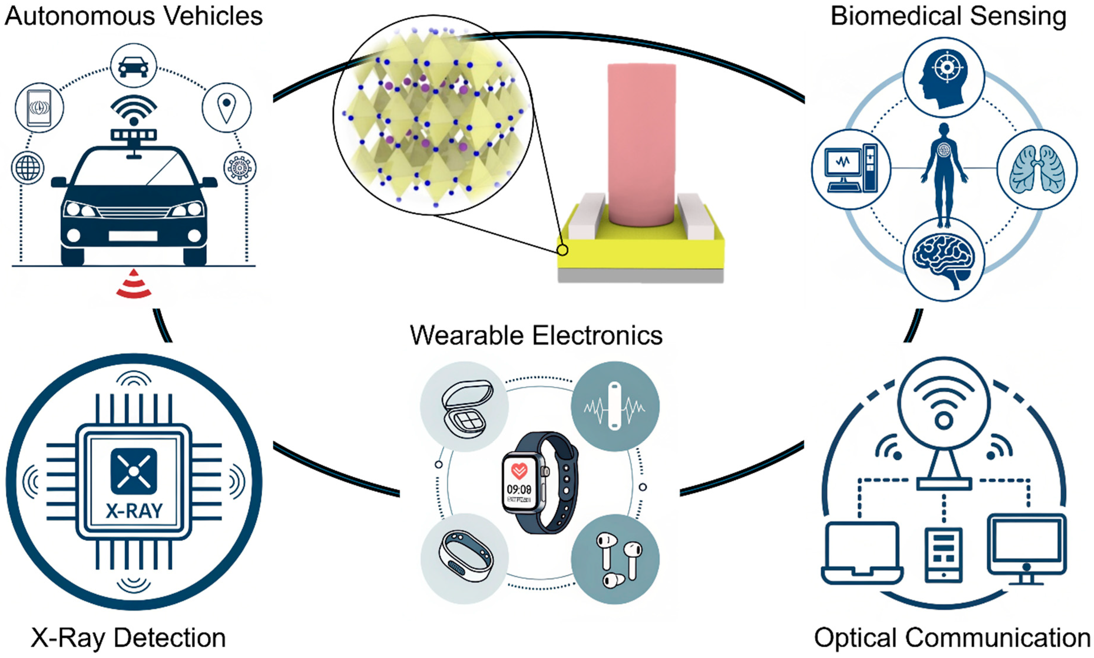
Figure 1. Pe-PDs and their diverse applications in X-ray detection, wearable electronics, autonomous vehicles, artificial intelligence, imaging, optical communication, and biomedical sensing.
Inorganics 13 00351 g001
Figure 2. Schematics of the surface plasmons. (a) Propagating surface plasmon generated (SPP) at the metal-dielectric interface. (b) localized surface plasmon resonance (LSPR) induced in the metal nanoparticles. (c) Plasmon-driven far-field and near-field scattering, hot electron transfer (HET), and plasmon resonant energy transfer.
Inorganics 13 00351 g002
Figure 3. (a) SEM images comparing CsPbBr3 nanocrystal (NC) films fabricated by drop-coating. (b) Schematic demonstration of device configuration. (c) The simplified schematic structures of the simulation model [74]. Copyright © 2016 Wiley-VCH. (d) Scheme of the PD based on (PEA)2PbI4 SC. (e) Electric field distributions in the x–y plane at absorption peak wavelength of (PEA)2PbI4 SC with Au NPs (tAu = 5 nm) [75]. Copyright © 2023 Wiley-VCH GmbH. (f) Schematic of the device architecture used in this study [76]. Copyright © 2016 Royal Society of Chemistry. (g) Schematic of a graphene dual hybrid PD composed of a perovskite material and GNSs with illustration of the key role of each component in the synergistic effect for optical sensing [77]. Copyright © 2020 Springer Nature.
Inorganics 13 00351 g003
Figure 4. (a) The schematic illustration of PQDs/Au NCs/Gr hybrid electrostatic gate-free. (b) FE-SEM image of sphere, octahedral (OD), and rhombic dodecahedron (RD) Au NCs, respectively [78]. Copyright © 2023 Wiley-VCH GmbH. (c) The scheme of the perovskite/PEDOT–PSS photodetector comprising the Au NPs-MPA assembly embedded in the PEDOT–PSS layer. (d) The calculated electric field intensity distribution of plasmonic nanostructures at 980 nm [79]. Copyright © 2021 Elsevier B.V.
Inorganics 13 00351 g004
Figure 5. (a) Schematic of the fabrication methodology for the perovskite photodetector. (b) Absorbance density profiles of the control device, w/Au NR, and w/Au NR/PEIE Pe-PDs at λ = 680 nm, calculated from FDTD simulations [80]. Copyright © 2025 Elsevier Ltd. (c) Schematic of fabrication process. (d) Analyses of local electric field enhancement of Ag NP with different excitation wavelengths, and the influence of spacing distance under constant excitation wavelength [81]. Copyright © 2024 IEEE. (e) Ag/OPCs hybrid model for 3D FDTD simulation and simulated electric field intensity distribution of Ag/OPCs film at 410 nm (top view) [82]. Copyright © 2018 Wiley-VCH GmbH. (f) SEM image of a CsPbBr3 NW covered with physically isolated Ag NPs, along with an enlarged view of the Ag NPs [83]. Copyright © 2023 Royal Society of Chemistry.
Inorganics 13 00351 g005
Figure 7. (a) Schematic for circularly polarized emission via chiral Fano resonances, (b) cross-sectional view of the structure, (c) simulated differential reflection spectrum ΔR (RRCPRLCP) [104]. Copyright © 2021 American Chemical Society. (d) Schematic of the chiral metasurface unit, (e) large-magnification SEM of an L-gammadion unit composed of CsPbBr3 perovskite NCs (top) and glum spectra (bottom), (f) schematic illustration of the fabrication process of chiral metasurfaces [105]. Copyright © 2023 Wiley. (g) Scheme of the fabrication process of 2D-chiral metasurfaces, (h) glum spectra [106]. Copyright © 2024 Wiley. (i) Schematic of a left-handed perovskite chiral metamolecule on quartz substrate, (j) experimental CD spectra of unpatterned MAPbI3 film, right- and left-handed perovskite chiral metasurfaces [107]. Copyright © 2022 Nature Portfolio. (k) Schematic of the cavity formed by a metal mirror and a metamirror, (l) device geometry [108]. Copyright © 2023 American Association for the Advancement of Science. (m) Schematic illustration of possible interactions between Au NPs and Cs0.05FA0.5MA0.45Pb0.5Sn0.5I3, (n) device structure of the CPL Pe-PD [109]. Copyright © 2022 Wiley.
Inorganics 13 00351 g007
Table 1. Performance summary of reported plasmonic Pe-PDs and chiral nanostructure-integrated perovskite emitters and Pe-PD.
Plasmonic StructureDevice StructureWavelength (nm)Performance (with Plasmonics)Improvement (%)Ref
Au NPsAu/CsPbBr3–Au NP film/Au NPs/Si532Iph = 831.1 μA, On/Off = 1.66 × 10⁶, D* = 4.56 × 10⁸ JonesIph = 238, On/Off = 1000[74]
Au NPsAg/(PEA)2PbI4/Au NPs/Glass565D* = 8.1 × 10¹⁴ JonesEQE (650–900 nm) = 1000, EQE (480 nm) = 68.5, D* = 200[75]
Au NPsPerovskite/Graphene/Au NPs/Si/SiO2530R = 2 × 10³ A W−1 R = 200[76]
Gold nanostars (GNSs)Perovskite/Graphene + GNS/Substrate532R = 5.90 × 10⁴ A W−1, D* = 1.31 × 10¹³ JonesR = 7.7 × 10⁸, D* > 10000[77]
Au NCs (sphere/OD/RD)PQDs/Graphene + Au NCs/Substrate432R = 2.7 × 10⁵ A W−1, D* = 4.9 × 10¹³ Jones, EQE = 7.9 × 10⁷%Iph = 1000[78]
Au NP chainsPerovskite/PEDOT–PSS + Au NP chains/Substrate635R = 2063 A W−1, NEP = 1.93 × 10¹⁴ W Hz−1/2, D* = 1.16 × 10¹² JonesR = 410, NEP = 1560[79]
Au NRs + PEIEMAPbI3/Au NRs + PEIE/ITO700R = 0.360 A W−1, D* = 1.81 × 10¹⁰ Jones, Idark = 2.93 × 10⁻¹⁰ A Idark = 76%[80]
Ag NPs + SU-8Perovskite/Ag NPs + SU-8/Glass632Iph = 0.86 μA, R = 0.478 A W−1, D* = 5.04 × 10¹⁰ Iph = 352.6, R = 4.6, D* = 354[81]
Ag NPs + PMMA OPCsCsPbCl3/Ag NPs + OPC/Substrate.410R = 8.1 A W−1, D* = 9 × 10¹⁴ Jones, τrise/fall = 28/31 ms τrise/fall = 40–50%[82]
Ag NPsCsPbBr3 microwire/Ag NPs/p-GaN530R = 63.9 A W−1, D* = 4.05 × 10¹² Jones, EQE = 1.5 × 10⁴%R = 550, D* = 600[83]
Au nanosquare arrayMAPbI3 on patterned Au800EQE > 65%, IPh = 4.6 nAEQE = 250, IPh = 900[84]
Au nanotrianglesMAPbI3 + Au triangles450R = 51 mA W−1, EQE = 12.6%EQE = 300[85]
Al NP on AAOCsPbBr3/Al NPs/AAO490R = 4.8 mA W−1, EQE: 1.12%IPh = 4800, EQE = 4000[86]
CN-patterned AuSi/SiO2/PS/Cr/Au/PVA/MAPbI3/Au 670R = 588.6 mA W−1, EQE: 109%, D* = 22.5 × 10¹¹ JonesR = 420, EQE = 420, D* =346[63]
I-shaped perovskite metasurfaceCsFAMA/PEDOT: PSS/metasurface0.1 (THz)R = 94 A W−1, NEP = 5.03 pW Hz−1/2, D* = 3.28 × 10¹⁰, stability retained (<2% change after 240 days)N/A[87]
Au nanoislandsMAPbI3/plasmonic Au/TiO2 nanodiode563IPh = 552 nA IPh = 400[66]
Triangular Ag
nanopatterns
Triangular Ag nanopatterns/Al2O3/Perovskite/PMMA800glum (dissymmetry factor for luminescence) = 1.084 (MAPbI3), 0.524 (MAPbBr3) N/A[104]
Chiral perovskite
metasurfaces
Nanoimprinted gammadion-shaped 2D-chiral perovskite nanocrystal metasurfaces520glum = 0.16 (CsPbBr1I2) N/A[105]
TiO2-coated chiral metasurfaces 2D gammadion perovskite nanocrystal arrays540glum = 0.56 (CsPbBr3) at 540 nmN/A[106]
Focused Ion Beam-assisted gammadion perovskite metasurfaces750gCD (dissymmetry factor for absorbance) = 0.49 (MAPbI3) N/A[107]
Triangular silicon chiral metasurfaceTriangular silicon chiral metasurface/ITO/PEDOT–PSS/CsPbBr3/TPBi/LiF/Al520gEL (dissymmetry factor for electroluminescence) = 0.76N/A[108]
Chiral Au NPsITO/chiral Au NPs/perovskite/PCBM/C60/BCP/Ag808 gres (dissymmetry factor for responsivity) = 0.55 (Cs0.05FA0.5MA0.45Pb0.5Sn0.5I3), R = 0.35 A W−1, D* = 1.54 × 10¹³ Jones, EQE = 54.2%, Bending radius = 2.5 cm (without degrading gres), 90% retention of initial gres after the 1000 cycle testN/A[109]
Disclaimer/Publisher’s Note: The statements, opinions and data contained in all publications are solely those of the individual author(s) and contributor(s) and not of MDPI and/or the editor(s). MDPI and/or the editor(s) disclaim responsibility for any injury to people or property resulting from any ideas, methods, instructions or products referred to in the content.