Article

Accessible Thermoelectric Characterization: Development and Validation of Two Modular Room Temperature Measurement Instruments

1
Faculty of Materials, Metallurgy and Recycling, Technical University of Košice, Letná 9, 042 00 Košice, Slovakia
2
Institute of Materials Research, Slovak Academy of Science, Watsonova 47, 040 01 Košice, Slovakia
*
Author to whom correspondence should be addressed.
Inorganics 2025, 13(10), 333; https://doi.org/10.3390/inorganics13100333 (registering DOI)
Submission received: 24 August 2025 / Revised: 25 September 2025 / Accepted: 2 October 2025 / Published: 4 October 2025
(This article belongs to the Section Inorganic Materials)

Abstract

This paper describes two low-cost, modular instruments developed for rapid room-temperature characterization of mainly thermoelectrics. The first instrument measures the Seebeck coefficient across diverse sample geometries and incorporates a four-point probe configuration for simultaneous electrical conductivity measurement, including disk-shaped samples. The second instrument implements the Van der Pauw method, enabling detailed investigation of charge carrier behavior within materials. Both devices prioritize accessibility, constructed primarily from 3D-printed components, basic hardware, and readily available instrumentation, ensuring ease of reproduction and modification. A unique calibration protocol using pure elemental disks and materials with well-established properties was employed for both instruments. Validation against comparable systems confirmed reliable operation. Control and data acquisition software for both devices was developed in-house and is fully documented and does not require an experienced operator. We demonstrate the utility of these instruments by characterizing the electronic properties of polycrystalline SnSe thermoelectric materials doped with Bi, Ag, and In. The results reveal highly complex charge carrier behavior significantly influenced by both dopant type and concentration.

1. Introduction

The ever-growing global demand for energy necessitates the development and utilization of new, preferably renewable, energy sources. Harvesting waste heat is one of the options to harness additional energy. Thermoelectrics are a promising approach for this task, allowing reversible conversion between electrical and thermal energy based on Seebeck and Peltier effects. The efficiency of thermoelectric material is described by the dimensionless figure of merit zT as follows [1,2,3,4,5,6,7,8,9,10,11]:
z T =   α 2 σ κ T
where α denotes the Seebeck coefficient, σ the electrical conductivity, κ the thermal conductivity, and T the absolute temperature. The term ‘α2σ’ is often referred to as ‘power factor’. It is particularly important when considering thermoelectric generators (TEGs) because it directly affects their power output [11]. The Seebeck coefficient cannot be measured directly but can be calculated using the following expression [1,2,12,13]:
α = V ( T h T c )
where V is the voltage/potential and (Th − Tc) is the temperature gradient. A few commercial instruments are available for determining the Seebeck coefficient, but most are expensive and impose restrictions on sample geometry. Consequently, many research groups have developed their own instruments optimized for specific materials [1,2,3,12,13,14,15]. Our work was inspired primarily by the setup described by de Boor [16]. While their instrument was originally designed for measuring electrical conductivity only, we modified it to enable Seebeck coefficient determination as well.
Electrical conductivity is another part of the power factor calculation, and unlike the Seebeck coefficient, it can be measured directly. Several measurement techniques exist, with the most common being variations of the four-probe method. Both instruments described in this work utilize the four-probe approach, albeit in different configurations. One is a modification of the “traditional” setup with two sense and two load probes but adapted to accommodate disk-shaped samples. The other is based on the Van der Pauw (VDP) method, which is particularly suitable for semiconductors. In the VDP method contacts are arranged in a square/circular geometry. Electrical resistivity is determined from the following formulas [4,17,18,19,20]:
ρ A =   π ln 2 f A t s ( V 1 V 2 + V 3 V 4 ) 4 I
ρ B = π ln 2 f A t s ( V 5 V 6 + V 7 V 8 ) 4 I
ρ A V G = ρ A + ρ B 2
where ρA and ρB are resistivities obtained for selected positions, ρAVG is their average value, fA is a geometric correction factor (equal to 1 for symmetric shapes), ts is the sample thickness, and V# and I# represent the respective voltage at each measurement position. Additionally, the VDP method allows further investigation of charge carrier behavior through the introduction of a homogenous magnetic field. This enables determination of the Hall coefficient (R) and charge carrier mobility (µH) [20]:
R H C = t s ( V 4 2 + V 2 4 + + V 2 4 V 4 2 ) 4 B I
R H A V G = R H C + R H D 2
μ H R H A V G ρ A V G
where RHC and RHD are Hall coefficients measured at different positions; RAVG is their average value; B is the applied magnetic flux density; and V# is for each required position. Index stands for points between which voltage is measured and sign indicates the direction of the magnetic field.
To verify the accuracy and reproducibility of the instruments, reference materials were employed. For demonstration of their full functionality, polycrystalline SnSe thermoelectrics from our previous work were used [21].

2. Materials and Methods

Polycrystalline-doped SnSe alloys were prepared via the powder metallurgy method. Pure elemental powders (purity 99.9%, Sigma Aldrich, Darmstadt, Germany) were weighed and thoroughly mixed. The mixed powder was placed into a porcelain vessel, which was then evacuated (up to at least 1 × 10⁻² mbar) and flushed with argon three times to reach a pressure slightly above atmospheric. Subsequently, the sample was gradually heated to 500 °C (at a rate of 5 °C/min) under an argon atmosphere. The resulting SnSe melts were crushed into powders and used for material properties analysis. Afterwards, they were compacted to disk shape using spark plasma sintering (SPS, FCT Systeme GmbH SPS HP D10-SD, Frankenblick, Germany).
The mechanochemical synthesis of tin selenide (SnSe) was achieved through co-milling tin powder with selenium powder (the same powders were used as for the other synthesis) using a planetary ball mill PM100 (Retsch GmbH, Haan, Germany). Both syntheses follow the reaction (Me, representing dopant):
Sn1−X + MeX + Se1 → Sn1−XMeXSe1
The milling was conducted with a stainless-steel milling chamber and balls (10 mm diameter), with a total ball mass of 73.46 g in a 50 mL chamber. The powder mixture consisted of 0.61 g of tin and 0.39 g of selenium, resulting in a ball-to-powder ratio of approximately 73:1. Milling was performed under an argon atmosphere at 500 rpm for 10 min. The resulting product was compacted to the disk shape using the same SPS machine.
Chemical composition of mechanochemically prepared samples was verified using an XRF spectrometer (Niton™ XL3t GOLDD+, Thermo Fisher Scientific, Waltham, MA, USA) on sintered samples. The composition was consistent with the intended Bi concentration. Phase composition was analyzed by X-ray diffraction (Philips X’Pert Pro, Co lamp, Amsterdam, The Netherlands). In the undoped SnSe sample, one additional peak appeared at 37° 2θ, corresponding to unreacted Sn. Increasing milling time to 30 min did not eliminate this residual Sn. However, in doped materials, only the SnSe phase was observed, with no additional peaks detected. Furthermore, no shifts in diffraction peak positions were identified (Figure 1). More details about the synthesis, analysis, and compaction can be found in our previous work [21]. Compared to the previous work, all systems of doped materials have now been expanded.

2.1. Instrument THEMA

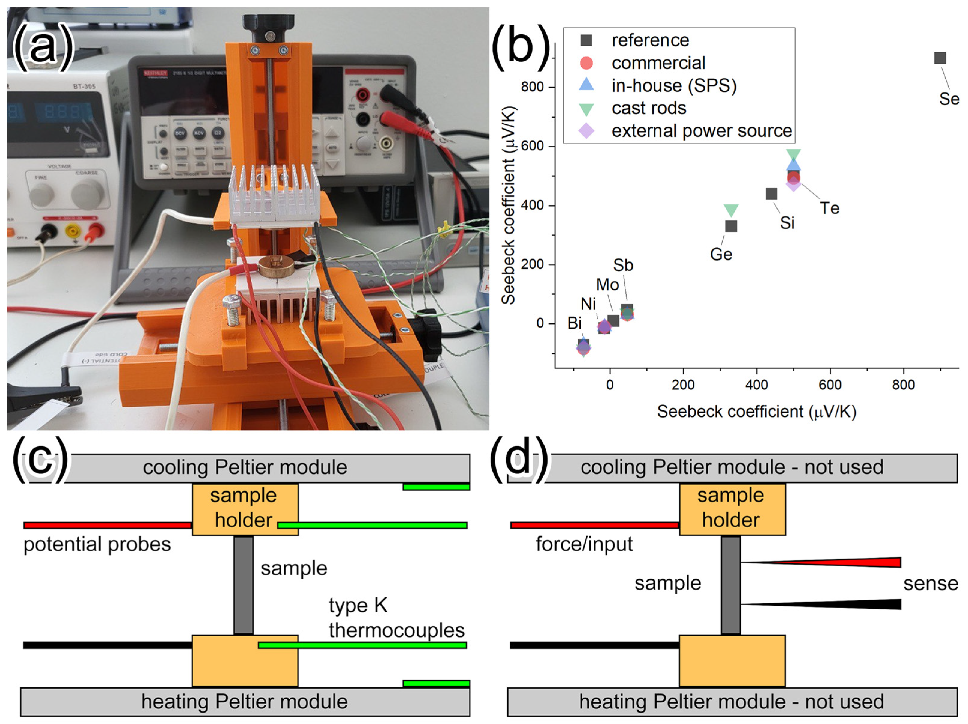
Our current in-house developed instrument for measuring thermoelectric properties at room temperature is called THEMA (THermo Electric Measuring Apparatus, Figure 2a). It was inspired by the instrument described in the work of de Boor [16]. We also retained their initial application for determination of electrical conductivity. The current configuration consists of a modular sample holder, two adjustable DC power supplies (Riden RD6006, Hangzhou, China), a multimeter (Keithley 2100, Cleveland, OH, USA), Peltier modules (TEC1-12715, Shenzen, China), and multiple thermocouples (type K, datalogger Pico Technology TC-08, Cambridgeshire, UK). Many of these components can be substituted with alternatives. The sample holder is made from brass, machined to a specific geometry. The sample stage is 3D printed and designed as a modular platform to accommodate various sample geometries.
Electrical contact was checked using the multimeter, and contact pressure was adjusted as needed. During Seebeck coefficient measurements, a temperature difference of 7–10 °C was applied. Measurements began at room temperature, with sample sides heated and cooled simultaneously at the same rate. Dynamic mode was used, and results from the system heating phase as well as the coming-to-equilibrium phase were averaged. Each measurement was performed at least three times with the sample rotated a bit each time. For anisotropy measurements, disks were measured both “flat” and “standing”. During data processing, the correction formula obtained from calibration was applied to all Seebeck coefficient results.

2.2. Instrument RelaMag

Similarly to THEMA, RelaMag uses the same multimeters and DC power supply. One multimeter measures potential, and the other measures current. Potential and current signals represent four inputs that require switching in the Van der Pauw method. To assign these four inputs to one of the four outputs, we used a switching layer. This layer consists of an XL9535-K16V5 board and a Raspberry Pi Pico W. Custom firmware was developed for the XL9535-K16V5 board to enable the intended functionality. Raspberry Pi is used to control this board. The magnetic field was measured using a Gaussmeter (HGM09s, MAGSYS magnet system GmbH, Dortmund, Germany). Custom sample and magnet holders were designed and 3D printed to achieve required geometries for accurate Van der Pauw measurements.
Control and data collection software was written in Python3. It controls all connected devices, runs in console mode, and guides the user to set measurement parameters, monitor the measurement itself, and transition to measure in the presence of a magnetic field.
Before each measurement, electrical contact was checked using the multimeter. A quick trial run was then performed on an unknown sample to validate current parameters to prevent excessive heating. Default parameters used for measurement were as follows: 3 V, 0.1 A, 0.4 T, 5 measurements at each position, and 3 cycles of all positions. All of these values are user-defined, and the final one required is sample thickness, which was determined using digital calipers.

3. Results and Discussion

Characterization of thermoelectrics might seem trivial based on the relatively simple equation describing their efficiency in the form of zT (Equation (1)). However, each input presents challenges in obtaining accurate values reliably. Commercial equipment used for thermoelectric characterization is usually very complex, restrictive, and expensive. Our main aim was to develop instruments that can be used for quick, reliable, and inexpensive determination of the Seebeck coefficient and electrical properties of studied materials at room temperature. We initially developed a single instrument capable of measuring the Seebeck coefficient and electrical conductivity of thermoelectric materials with various geometries. However, we were not satisfied with the electrical conductivity results from this instrument and therefore decided to develop another system with expanded functionality based on the Van der Pauw method. Both instruments proved reliable in rapid room temperature characterization of materials, including but not limited to thermoelectrics.

3.1. Instrument for Seebeck Coefficient THEMA

Determination of the Seebeck coefficient is based on Equation (2). The instrument must be capable of measuring electric potential and temperature simultaneously. Measuring electric potential alone was straightforward, and we decided to use a multimeter sufficiently sensitive to detect voltages generated by the Seebeck effect. However, making reliable electrical contact with thermoelectric samples, which often exhibit low electrical conductivity, is challenging. To solve this issue, along with several other challenges, we prepared brass sample holders with very specific geometry. The inner part of the sample holder was machined to a specific shape to securely hold samples of varied geometry. The outer circumference was machined with holes to attach potential and temperature probes. The shape of the sample holder was inspired by the work of Boor [16] and is also used to determine electrical conductivity based on the method described in the same work. Brass was selected because of its good machinability and favorable electrical and thermal conductivities. We tested multiple methods of creating a temperature difference. Hot air proved unreliable, while resistive heaters were difficult to control without a PID system. In the end, we decided to use Peltier modules, which are both controllable and reliable. One Peltier module was used as a heater and another as a cooler, thereby allowing the creation of a very stable temperature gradient. Typically, in other similar instruments, the temperature gradient is created only by heating one side while maintaining the second at ambient temperature. Initially we also used this configuration but decided to add a cooler to prevent temperature creep. Sample holders were mounted at the middle of the Peltier modules. Uniform heat transfer between the heater, sample holder, and sample itself was verified using thermography. Another challenge was accurate temperature measurement. We tested multiple methods during instrument development, including thermistors, thermocouples, and thermography. The first prototype used glass bead thermistors, but their shape proved unsuitable for reliable and repeatable measurements. Thermocouples offer multiple connection possibilities. The current setup utilizes two thermocouples and two potential probes. All of them are attached to the sample holder in a very close proximity to the sample contact points. In the end we decided against using differential thermocouples, which could offer a simple solution for potential and temperature probes in one connection. In our setup thermocouples are not connected to the sample directly. Instead, they measure through the sample holder, which is electrically isolated from the thermocouples using a thin layer of Teflon tape. This tape prevents thermocouple degradation and improves its accuracy by eliminating Galvani voltage. Our decision to isolate thermocouples and samples was further supported by the fact that some of our materials contain sulfur, which can degrade certain thermocouple types. The completed instrument, along with schematics of its operation, is shown in Figure 2a,c,d.
To enable semi-automated operation of the instrument, we developed custom software controlling all devices. It is also used for data collection. The software was written in Python3. The user must set some parameters at the start in the GUI. Specifically, the current for the heater and cooler to control the temperature gradient. More details about the THEMA software can be found in the Supplementary Materials. Afterwards, the user can decide whether to operate in dynamic or static mode. In dynamic mode, data from the heating/cooling phase are used, while in static mode, only data from a maintained temperature gradient are considered. From our testing, both modes produced very similar results, and we typically use dynamic mode to monitor the material closer. An additional mode with an external power source was also implemented. In this mode, a potential difference is introduced to the sample holders by another external power source. This mode is useful for samples with low electrical conductivity or very low Seebeck coefficients because it assists the multimeter (which typically applies an internal 1 V potential during measurements).
We placed significant importance on instrument calibration. Calibration was essential for obtaining absolute values because the use of sample holders introduces parasitic Seebeck voltages between the sample and the sample holder. We obtained multiple disks of pure elements (Bi, Ni, Sb, and Te, with 99.9+% purity, provided by Moorfield Nanotechnology Limited, Knutsford, UK). All these elements have known values of the Seebeck coefficient. A multi-point calibration revealed that a linear correction must be applied to the data obtained from our instrument. Calibration results are shown in Figure 2b. The current correction formula for the absolute Seebeck coefficient ( S a b s ) as a function of the measured Seebeck coefficient ( S r e l ) for our system is:
S a b s = S r e l × 1.46 0.68474

3.2. Instrument for Electrical Conductivity RelaMag

During the ECT24 conference it was emphasized [22] that more focus in thermoelectrics should be turned to their electric properties and power factor to obtain usable TEGs in the near future. To study our materials further, we decided to create another custom instrument based on the recommended Van der Pauw method. After its completion, we named it RelaMag (derived from its core components: relays and magnets). We kept the same priorities of accessibility while minimizing compromises in accuracy. Our instrument is based on Equations (3)–(5) that were slightly modified according to the work of Lindemuth [23]. More details about the formulas used are available in Supplementary Materials to determine the electrical resistivity of the material. Voltage and current measurements are straightforward, and we used two multimeters together with a programmable DC power source to generate a current going through the material. The challenge arises from the large number of measurement configurations required. To reduce time and errors, we developed a custom switching layer. This layer consists of a Raspberry Pi microcontroller and a PCB containing 16 relays. This switching system accepts four inputs (positive and negative voltage and current) and routes them between any of the four outputs connected directly to the sample. The sample is contacted using four sharp brass probes. Switching is controlled by a specific “keyword” via our custom firmware for the XL9535-K16V5 board (further details and GitHub documentation are available upon reasonable request).
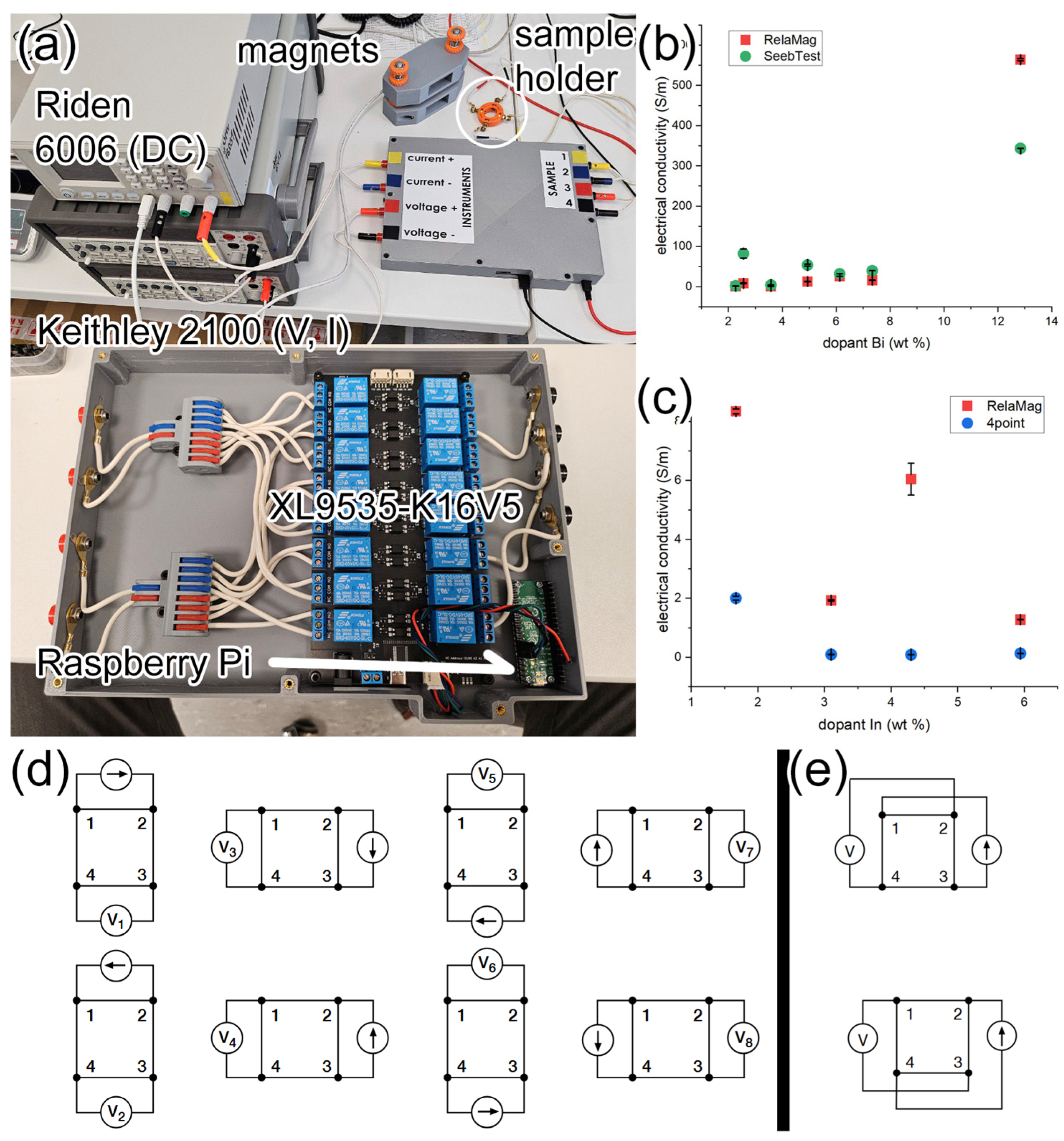
The Van der Pauw method can provide more information about the studied material when a magnetic field is introduced. The addition of a magnetic field enables determination of the Hall coefficient and charge carrier mobility. Current and voltage probe positions differ but are still assignable through our switching layer. Different magnet shapes and sizes were simulated using QuickField software (version 6.6) to optimize the configuration. Permanent magnets were then placed into a custom-designed holder that aligns them with the sample. To verify the simulation results, the magnetic field strength was measured using a Gaussmeter, and the obtained value from it was used in subsequent calculations. Although the magnets must be physically added and removed, we chose them over electromagnets because of the latter’s problematic cooling requirements under vacuum conditions, for which this instrument was also designed. The complete device can be seen in Figure 3a.
All devices integrated into this instrument are controlled via a single Python3 program. In addition to device control, the software also collects data and performs calculations according to Equations (3)–(9). The program provides users with numerous configurable parameters prior to measurement. Full software details and documentation are available upon reasonable request (hosted on GitHub). To verify the accuracy of our device, we compared electrical resistivity results obtained with RelaMag against those from a similar instrument developed at Warsaw University of Technology (Figure 3b). Results matched for most samples; for those that differed, we suspect that discrepancies were caused by measuring in different orientations and by slight changes in the material itself caused by nearly one year between measurements and several thermal cycles the samples underwent. Additionally, we compared RelaMag results with electrical conductivity obtained using the THEMA instrument based on the method proposed by de Boor [16] (Figure 3c). This method proved unsatisfactory for our samples and would likely require fine-tuning of parameters used for calculation even though our samples are similarly shaped and within limits stated in the reference work.

3.3. Polycrystalline-Doped SnSe Thermoelectric Properties at Room Temperature

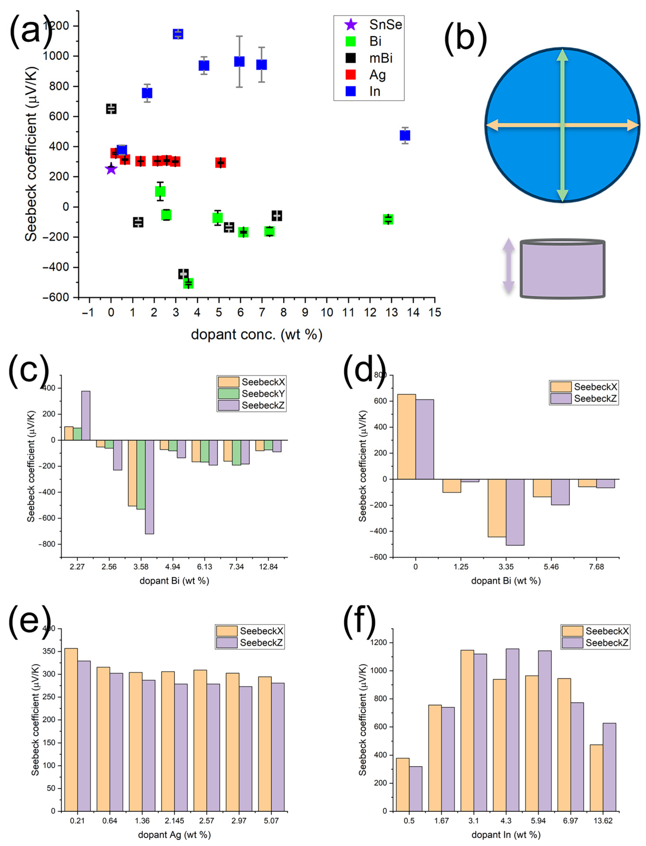
To showcase the capabilities of our devices, we analyzed an expanded series of doped (Bi, Ag, In) polycrystalline SnSe materials from our previous work [21]. We also included SnSe synthesized and Bi-doped materials via a mechanochemical pathway. Similarly to monocrystalline Sb-doped SnSe [25], we observed that low Bi concentration does not induce polarity switch in our SnSe material. However, increasing the concentration does not revert the polarity back, in contrast to reported monocrystalline Sb-doped SnSe (Figure 4a). We attribute this primarily to the Bi itself, as at higher concentrations, its charge carriers significantly affect the overall behavior of the material. The same behavior was observed in mechanochemically prepared materials. Ag and In doping did not produce a polarity switch even at lower or higher concentrations (Figure 4a). Because of our materials’ layered structure, we wanted to verify their anisotropy. The THEMA instrument accommodates disk-shaped samples in any orientation. After initial measurements (Figure 4c), we determined that properties along the circumference (Figure 4c green, orange) were isotropic and therefore not repeated for other materials. In Figure 4c, we can also see that significant anisotropy was observed in Bi-doped samples (the Seebeck coefficient was up to 70% higher in certain orientations). Anisotropy in In-doped materials was noticeable but less pronounced (Figure 4f). Meanwhile, Ag doping seemingly improved the homogeneity of the material, as essentially no anisotropy was observed even though the samples retained their typical layered structure (Figure 4e). We attribute this anisotropic behavior to the layering itself, since it is more difficult for charge carriers to move across layers than along them. Consequently, we usually observed higher Seebeck coefficient values when measurements were performed perpendicular to the layer orientation. Ag doping removed these anisotropic characteristics, rendering the material almost fully isotropic. Mechanochemical synthesis also reduced anisotropy; however, the Seebeck coefficient values remained similar (Figure 4d). Because anisotropy was observed in our materials, it is important not to use values obtained along different axes/planes interchangeably.
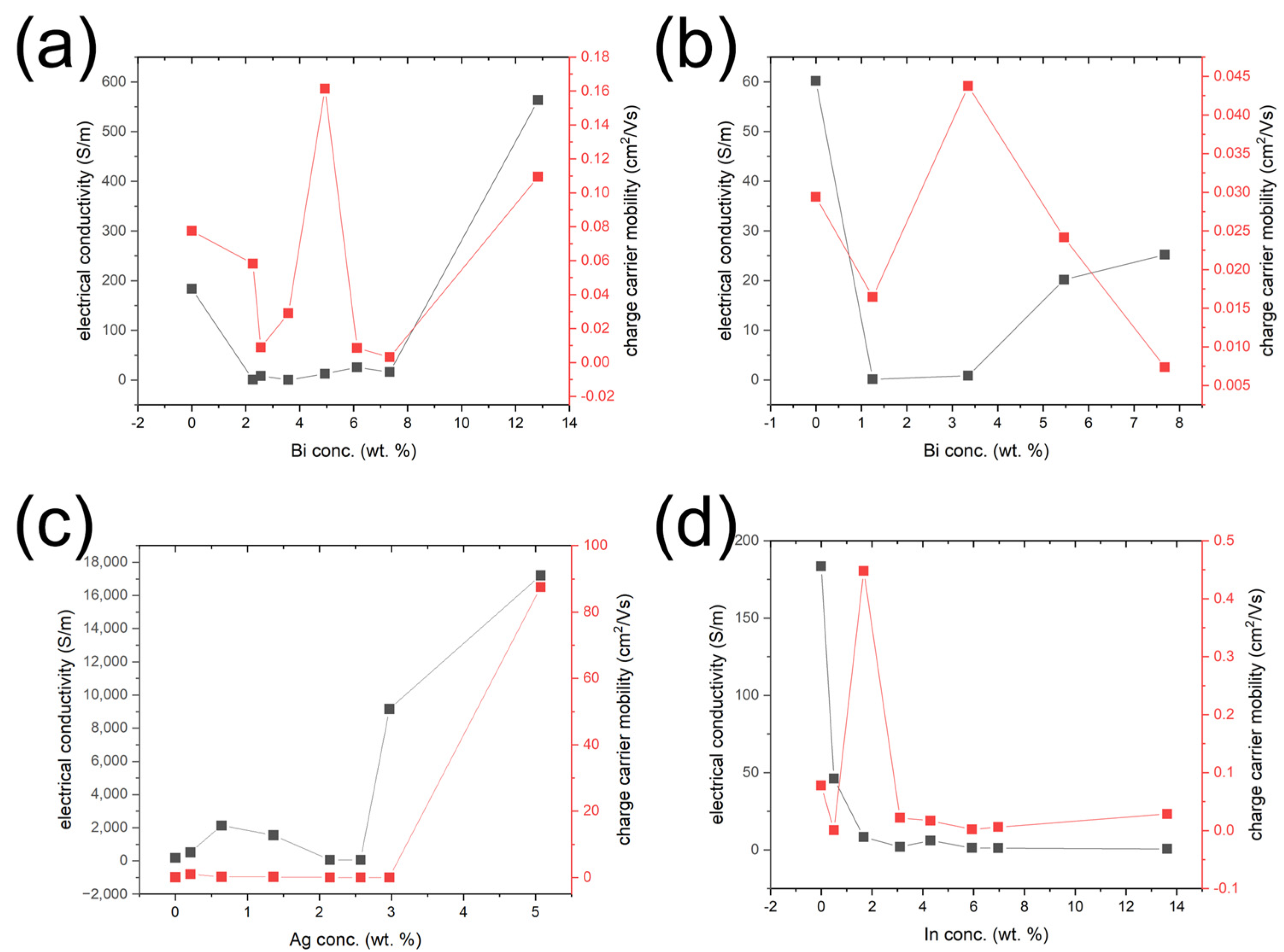
To study the electrical properties of our materials, we utilized the RelaMag instrument. Based on the limitations of the Van der Pauw method, we were only able to determine properties along the X and Y axes (Figure 4b, green and orange). Bi doping in most cases reduced electrical conductivity compared to pure polycrystalline SnSe (Figure 5a, b). Electrical conductivity was even lower for In-doped materials, showing a significant drop with increasing In concentration (Figure 5d). However, Ag doping, particularly at higher concentrations, significantly improved electrical conductivity (Figure 5c). No significant difference was observed between Bi-doped materials prepared using different synthesis techniques.
Hall coefficients for most of our materials were close to zero, suggesting a combination of electron and hole transport effects. Low charge carrier mobility explains the relatively high Seebeck coefficients in combination with low electrical conductivity values. This low mobility arises from charge carriers with high effective mass. The presence of these carriers leads to a slow material response, which allows the creation of higher potential differences but reduces electrical conductivity.

4. Conclusions

This work presents two in-house developed instruments designed for rapid and accurate room-temperature characterization of thermoelectric materials. The THEMA instrument is primarily intended for Seebeck coefficient determination. It can accommodate samples of various geometries, typical in thermoelectric research, without compromising accuracy. The RelaMag instrument determines electrical conductivity and also provides additional insight into charge carrier behavior by employing the Van der Pauw method, which restricts sample geometries to circular or square shapes. Both instruments rely on off-the-shelf components and 3D-printed parts, making them inexpensive, easily reproducible, and straightforward to modify. To demonstrate the capabilities of both instruments, we characterized our polycrystalline SnSe-based doped materials. We used two synthesis pathways to prepare our materials. Bi-doped materials prepared by powder metallurgy exhibited significant anisotropic behavior uncharacteristic of polycrystalline materials. Meanwhile, mechanochemically synthesized Bi-doped samples did not show anisotropy but retained similar Seebeck coefficient values and trends. In general, increasing Bi content reduced electrical conductivity in both synthesis routes. Ag doping did not significantly alter the Seebeck coefficient but suppressed anisotropy and notably improved electrical conductivity. In contrast, In doping induced slight anisotropy and led to a pronounced increase in the Seebeck coefficient, while simultaneously reducing electrical conductivity. The combination of relatively low charge-carrier mobility with high Seebeck coefficient values suggests that charge transport in these materials is dominated by heavy carriers. Beyond SnSe, the flexibility and modularity of the THEMA and RelaMag instruments make them broadly applicable to a wide range of thermoelectric systems, particularly for rapid screening of novel compositions potentially useful as thermoelectrics. Their low cost and ease of modification further highlight their potential as accessible tools for accelerating thermoelectric materials research.

Supplementary Materials

The following supporting information can be downloaded at: https://www.mdpi.com/article/10.3390/inorganics13100333/s1, File S1: THEMA GUI during a measurement is explained, detailed explanations are given for formatting of output files for THEMA and RelaMag instruments, formulas used for RelaMag are explained in greater detail, tables corresponding to select figures include data shown in them; File S2: msnse_example.csv contains an example output from THEMA instrument; File S3: Ag10_example.txt contains example output from RelaMag instrument.

Author Contributions

Conceptualization, F.M. and K.S.; methodology, F.M.; software, F.M. and K.S.; investigation, F.M., K.G., and V.P.; writing—original draft preparation, F.M.; writing—review and editing, F.M., K.G., and K.S.; visualization, F.M.; supervision, K.S. All authors have read and agreed to the published version of the manuscript.

Funding

This work was created with financial support from VEGA 1/0122/25 and APVV projects APVV-24-0111 and VV-MVP-24-0264.

Data Availability Statement

Material characterization, Seebeck coefficient, electrical properties, and software data/documentation from this submission can be provided upon reasonable request with a clear intent stated.

Conflicts of Interest

The authors declare no conflicts of interest.

References

  1. Narjis, A.; Elyaagoubi, M.; Outzourhit, A.; Nkhaili, L. Design of a Simple Apparatus for the Measurement of the Seebeck Coefficient. Measurement 2019, 133, 433–438. [Google Scholar] [CrossRef]
  2. Xiong, R.; Masoumi, S.; Pakdel, A. An Automatic Apparatus for Simultaneous Measurement of Seebeck Coefficient and Electrical Resistivity. Energies 2023, 16, 6319. [Google Scholar] [CrossRef]
  3. Zhou, Y.; Yang, D.; Li, L.; Li, F.; Li, J.-F. Fast Seebeck Coefficient Measurement Based on Dynamic Method. Rev. Sci. Instrum. 2014, 85, 054904. [Google Scholar] [CrossRef]
  4. Haupt, S.; Edler, F.; Bartel, M.; Pernau, H.-F. Van Der Pauw Device Used to Investigate the Thermoelectric Power Factor. Rev. Sci. Instrum. 2020, 91, 115102. [Google Scholar] [CrossRef]
  5. Candolfi, C.; El Oualid, S.; Lenoir, B.; Caillat, T. Progress and Perspectives in Thermoelectric Generators for Waste-Heat Recovery and Space Applications. J. Appl. Phys. 2023, 134, 100901. [Google Scholar] [CrossRef]
  6. Von Lukowicz, M.; Abbe, E.; Schmiel, T.; Tajmar, M. Thermoelectric Generators on Satellites—An Approach for Waste Heat Recovery in Space. Energies 2016, 9, 541. [Google Scholar] [CrossRef]
  7. Ganesan, P.; Gantepogu, C.S.; Duraisamy, S.; Meledath Valiyaveettil, S.; Tsai, W.-H.; Hsing, C.-R.; Lin, K.-H.; Chen, K.-H.; Chen, Y.-Y.; Wu, M.-K. Carrier Optimization and Reduced Thermal Conductivity Leading to Enhanced Thermoelectric Performance in (Mg, S) Co-Doped AgSbTe2. Mater. Today Phys. 2024, 42, 101358. [Google Scholar] [CrossRef]
  8. He, Q.; Yang, D.; Xia, S.; Song, H. Ultra-Low Thermal Conductivity and Improved Thermoelectric Performance in La2O3-Dispersed Bi2Sr2Co2Oy Ceramics. Mater. Sci. Eng. B 2024, 299, 116976. [Google Scholar] [CrossRef]
  9. Cai, Z.; Zheng, K.; Ma, C.; Fang, Y.; Ma, Y.; Deng, Q.; Li, H. Ultra-Low Thermal Conductivity and Improved Thermoelectric Performance in Tungsten-Doped GeTe. Nanomaterials 2024, 14, 722. [Google Scholar] [CrossRef]
  10. Chatterjee, A.; El Sachat, A.; Banik, A.; Biswas, K.; Castro-Alvarez, A.; Sotomayor Torres, C.M.; Santiso, J.; Chávez-Ángel, E. Improved High Temperature Thermoelectric Properties in Misfit Ca3Co4O9 by Thermal Annealing. Energies 2023, 16, 5162. [Google Scholar] [CrossRef]
  11. Parzer, M.; Kositz, A.; Süß, J.; Garmroudi, F.; Mori, T.; Bauer, E. Enhanced Thermopower by Double-Site Substitution of Ti in Fe2(VAl)1-xTi2x. Mater. Today Phys. 2025, 54, 101712. [Google Scholar] [CrossRef]
  12. Mulla, R.; Rabinal, M.K. A Low-Cost Apparatus to Measure the Seebeck Coefficient. Phys. Educ. 2021, 56, 015006. [Google Scholar] [CrossRef]
  13. Mishra, A.; Bhattacharjee, S.; Anwar, S. Simple Apparatus to Measure Seebeck Coefficient up to 900K. Measurement 2015, 68, 295–301. [Google Scholar] [CrossRef]
  14. Karpov, A.V.; Sytschev, A.E.; Sivakova, A.O. Device for Measurement the Seebeck Coefficient of Thermoelectric Materials in the Temperature Range 300–800 K. Meas. Tech. 2023, 66, 628–635. [Google Scholar] [CrossRef]
  15. Tarachand; Saxena, M.; Mukherjee, B.; Okram, G.S. A Load-Based Thermopower Measurement Setup in the Temperature Range of 5–330 K. Rev. Sci. Instrum. 2019, 90, 063904. [Google Scholar] [CrossRef]
  16. de Boor, J.; Zabrocki, K.; Frohring, J.; Müller, E. Electrical Conductivity Measurements on Disk-Shaped Samples. Rev. Sci. Instrum. 2014, 85, 075104. [Google Scholar] [CrossRef] [PubMed]
  17. Oliveira, F.S.; Cipriano, R.B.; Da Silva, F.T.; Romão, E.C.; Dos Santos, C.A.M. Simple Analytical Method for Determining Electrical Resistivity and Sheet Resistance Using the van Der Pauw Procedure. Sci. Rep. 2020, 10, 16379. [Google Scholar] [CrossRef]
  18. Pandey, S.K.; Manivannan, A. A Fully Automated Temperature-Dependent Resistance Measurement Setup Using van Der Pauw Method. Rev. Sci. Instrum. 2018, 89, 033906. [Google Scholar] [CrossRef]
  19. Rietveld, G.; Koijmans, C.V.; Henderson, L.C.A.; Hall, M.J.; Harmon, S.; Warnecke, P.; Schumacher, B. DC Conductivity Measurements in the van Der Pauw Geometry. IEEE Trans. Instrum. Meas. 2003, 52, 449–453. [Google Scholar] [CrossRef]
  20. Melios, C.; Huang, N.; Callegaro, L.; Centeno, A.; Cultrera, A.; Cordon, A.; Panchal, V.; Arnedo, I.; Redo-Sanchez, A.; Etayo, D.; et al. Towards Standardisation of Contact and Contactless Electrical Measurements of CVD Graphene at the Macro-, Micro- and Nano-Scale. Sci. Rep. 2020, 10, 3223. [Google Scholar] [CrossRef]
  21. Mihok, F.; Hricková, G.; Puchý, V.; Szabó, J.; Ballóková, B.; Džunda, R.; Saksl, K. Effect of Multiple Doping Elements on Polarity Switching of Polycrystalline SnSe Semiconductor. Inorganics 2024, 12, 103. [Google Scholar] [CrossRef]
  22. Snyder, G.J. Complex Thermoelectric Materials. In Proceedings of the 40th International Conference on Thermoelectrics, Krakow, Poland, 30 June–4 July 2024; Available online: https://thermoelectrics.matsci.northwestern.edu/publications/ICTComplexTE-2024.pdf (accessed on 1 October 2025).
  23. Lindemuth, J. Hall Effect Measurement Handbook: A Fundamental Tool for Semiconductor Material Characterization; Lake Shore Cryotronics, Inc.: Westerville, OH, USA, 2020; ISBN 978-1-7347078-0-9. [Google Scholar]
  24. Tektronix, Van Der Pauw and Hall Voltage Measurements with the 4200A-SCS Parameter Analyzer. Available online: https://download.tek.com/document/1KW-60641-0_vanderPauw_4200A-SCS_AN.pdf (accessed on 1 October 2025).
  25. Yamamoto, C.; He, X.; Katase, T.; Ide, K.; Goto, Y.; Mizuguchi, Y.; Samizo, A.; Minohara, M.; Ueda, S.; Hiramatsu, H.; et al. Double Charge Polarity Switching in Sb-Doped SnSe with Switchable Substitution Sites. Adv. Funct. Mater. 2021, 31, 2008092. [Google Scholar] [CrossRef]
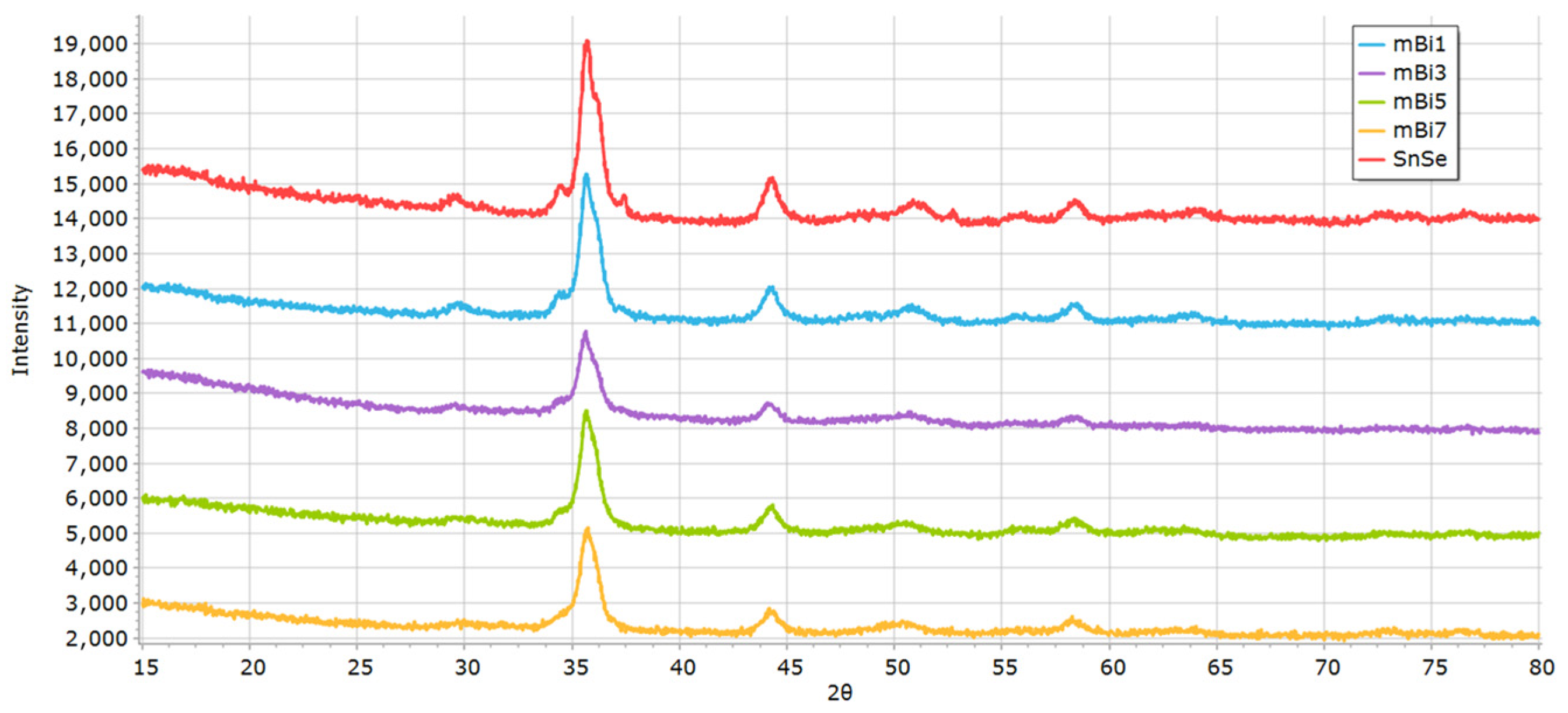
Figure 1. X-ray diffraction patterns for mechanochemically prepared materials.
Inorganics 13 00333 g001
Figure 2. (a) THEMA instrument; (b) Seebeck coefficient calibration with correction formula applied (reference being known Seebeck coefficient values; commercial being disks of 99.9% pure materials, initially sputtering targets; in-house being disk of pure elements prepared using SPS, cast rods being cast pure elements, and external power source data points were obtained using higher voltage); (c) schematics of THEMA instrument for Seebeck coefficient measurement; (d) schematics for electrical conductivity measurement.
Inorganics 13 00333 g002
Figure 3. (a) RelaMag instrument and description of its components; (b) comparison of results from instrument SeebTest used for Seebeck coefficient and electrical conductivity measurement at Warsaw Technical University; (c) comparison of results with four-probe setup on THEMA based on methodology proposed by de Boor [16]; (d) probe positions used for electrical resistivity measurements [24]; (e) probe positions used for measurements in magnetic field [24].
Inorganics 13 00333 g003
Figure 4. (a) Comparison of Seebeck coefficient values obtained for different dopants (mBi stands for Bi-doped materials prepared mechanochemically); (b) orientations used during anisotropy measurements; (c) Seebeck coefficient values measured across different orientations for Bi-doped materials; (d) for Bi-doped mechanochemically prepared materials; (e) for Ag-doped materials; (f) for In-doped materials.
Inorganics 13 00333 g004
Figure 5. (a) Values of electrical conductivity and charge carrier mobility obtained from the RelaMag instrument for Bi-doped materials; (b) for Bi-doped mechanochemically prepared materials; (c) for Ag-doped materials; (d) for In-doped materials.
Inorganics 13 00333 g005
Disclaimer/Publisher’s Note: The statements, opinions and data contained in all publications are solely those of the individual author(s) and contributor(s) and not of MDPI and/or the editor(s). MDPI and/or the editor(s) disclaim responsibility for any injury to people or property resulting from any ideas, methods, instructions or products referred to in the content.