A Multi-Layer Erbium-Doped Air-Hole-Assisted Few-Mode Fiber with Ultra-Low Differential Modal Gain


Abstract
1. Introduction
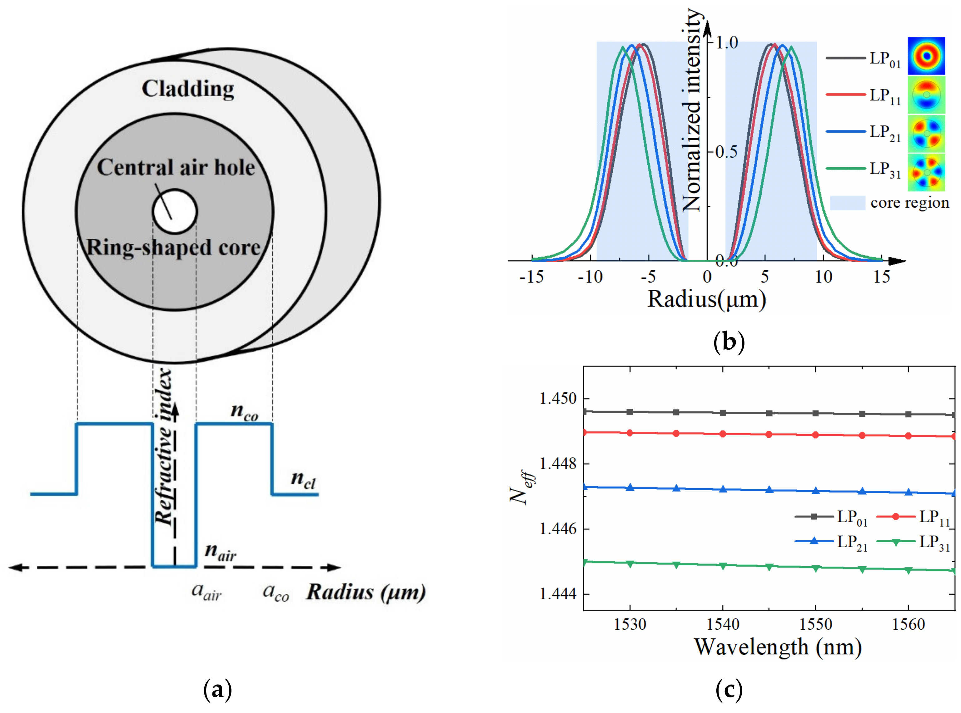
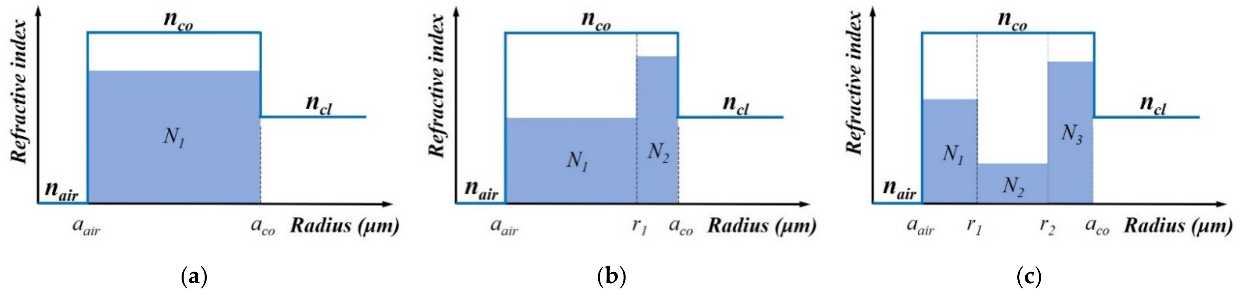
2. Theory and Model
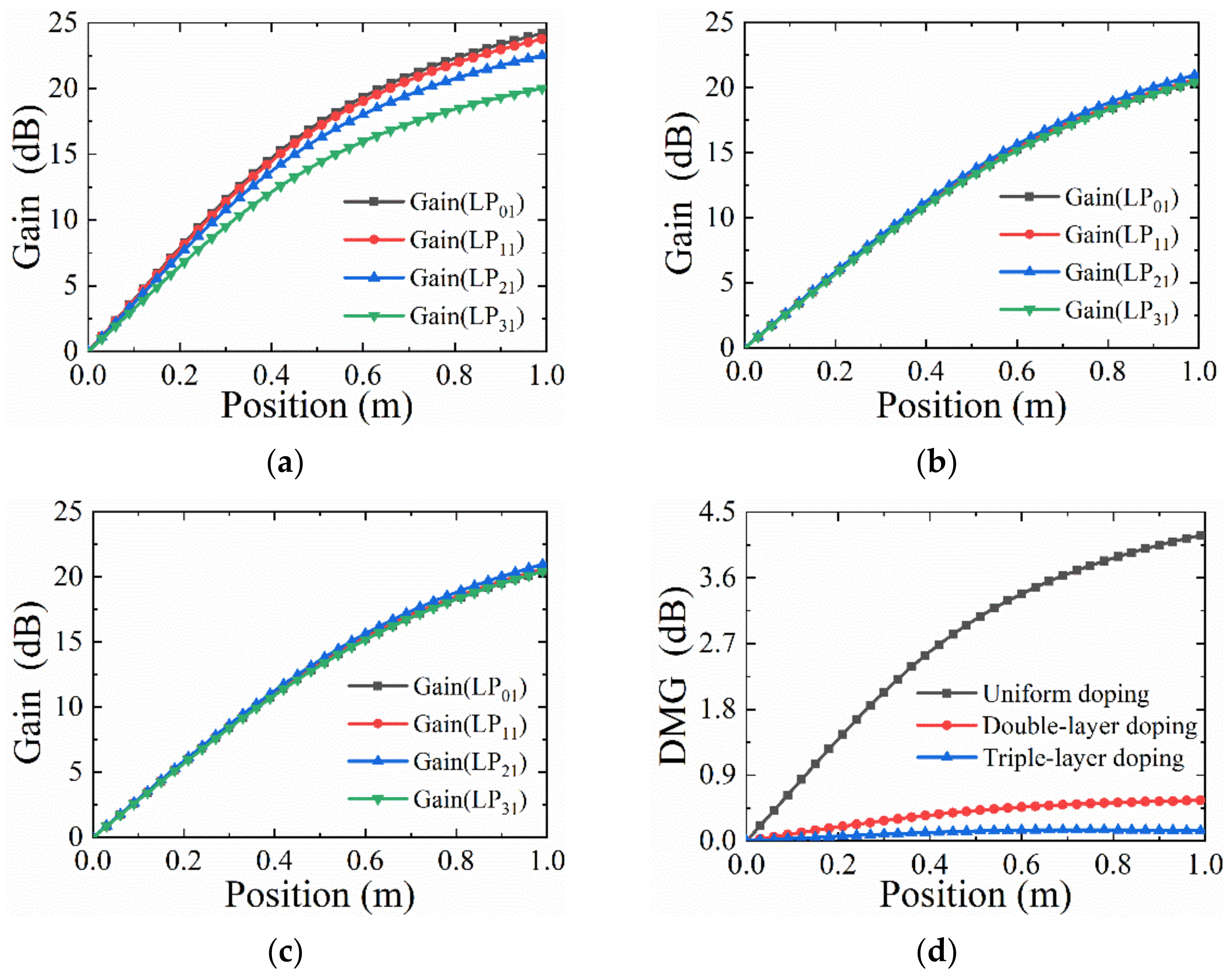
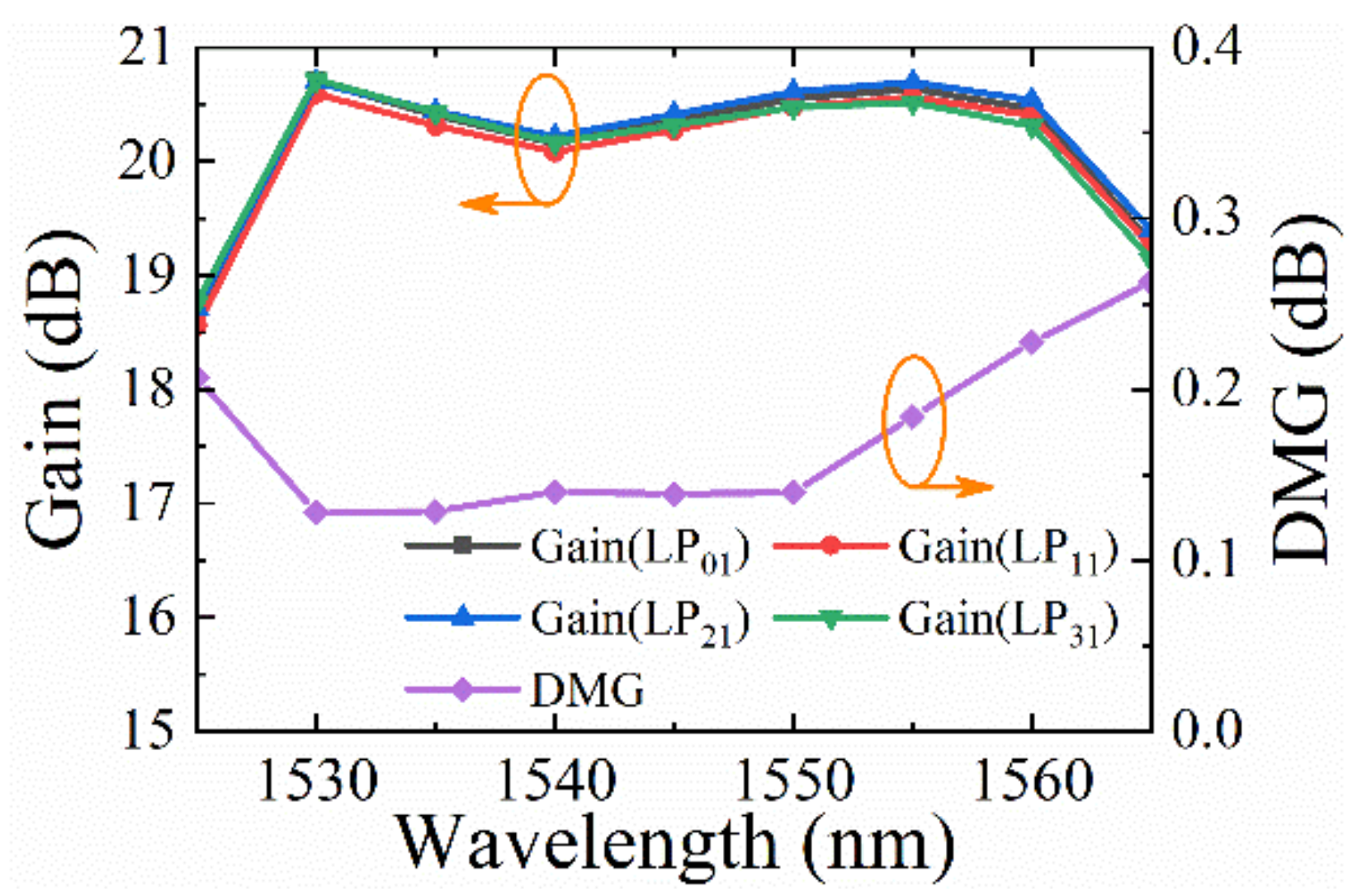
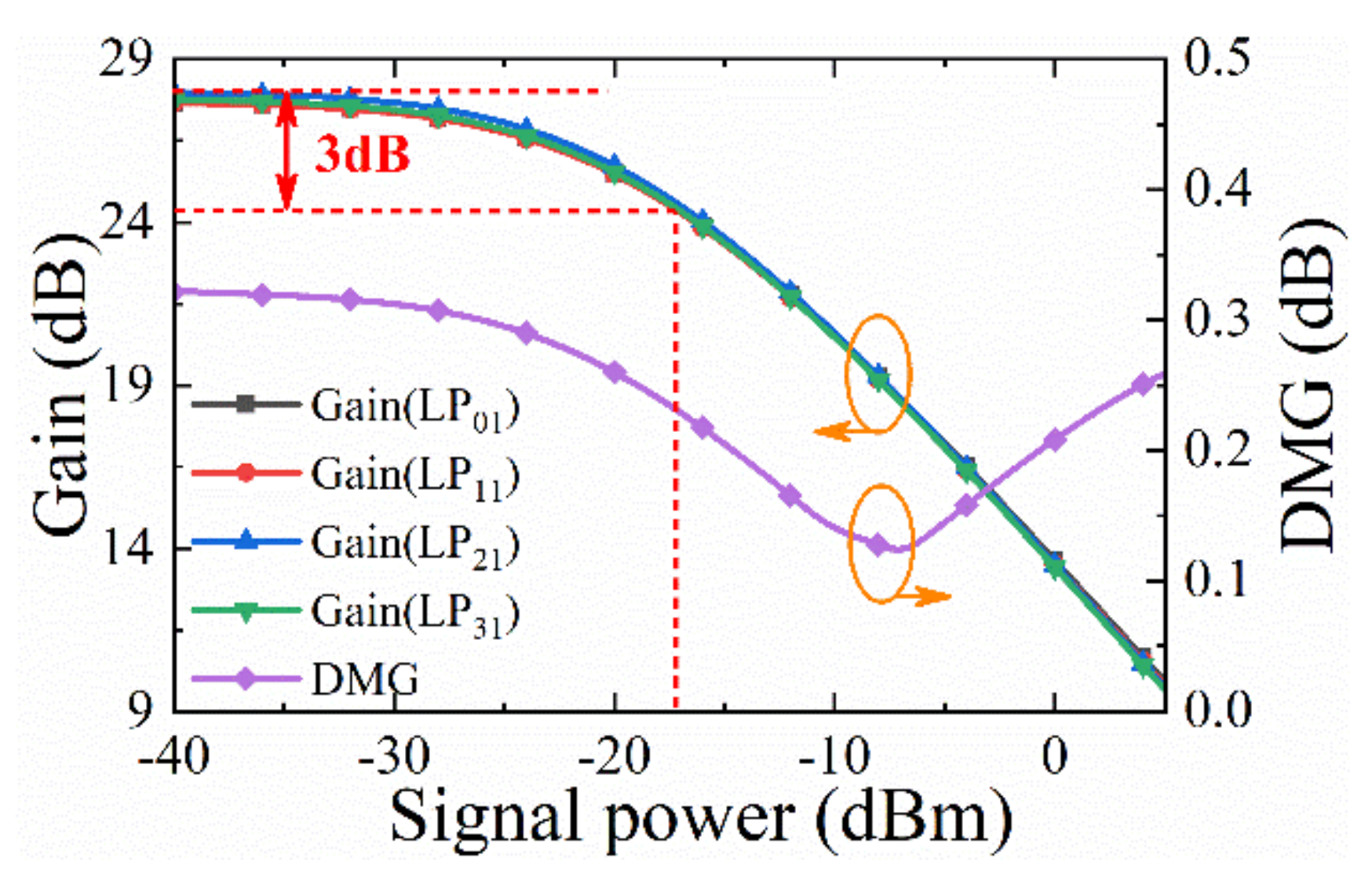
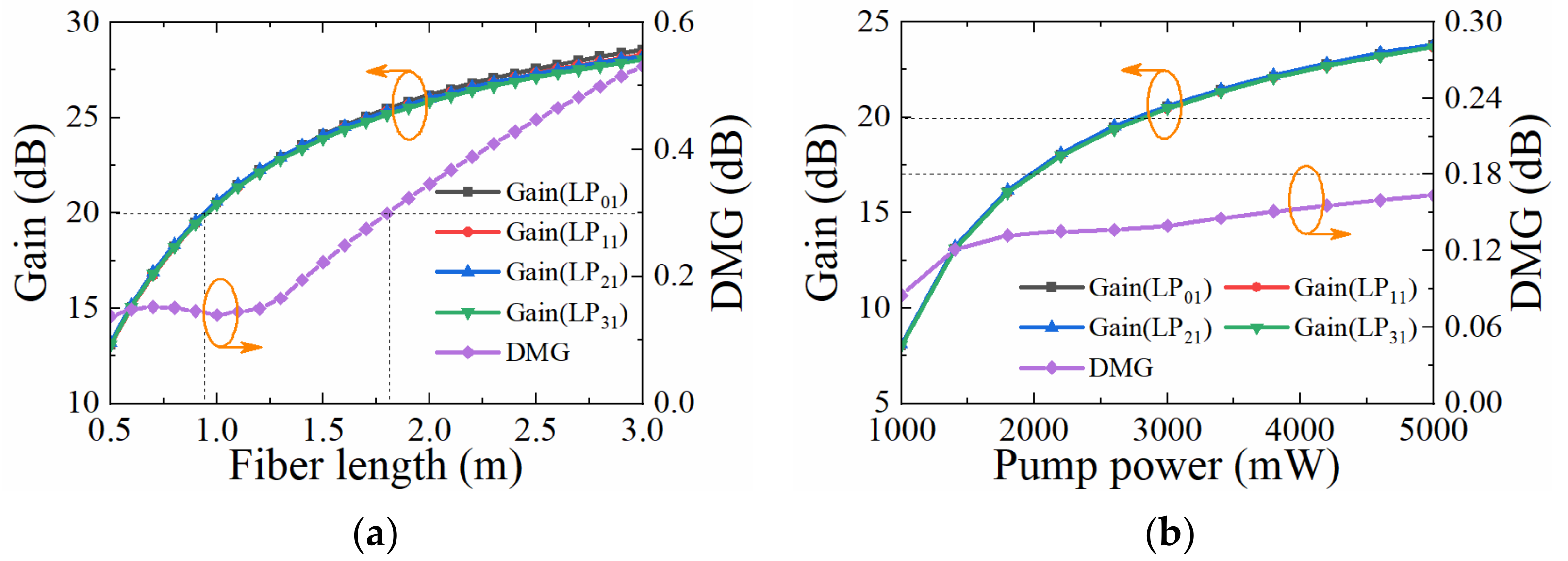
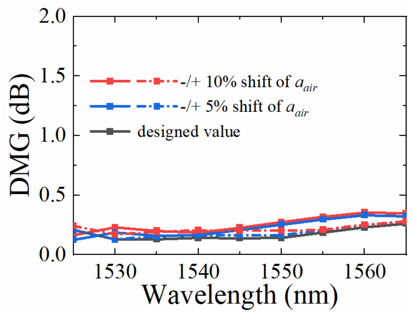
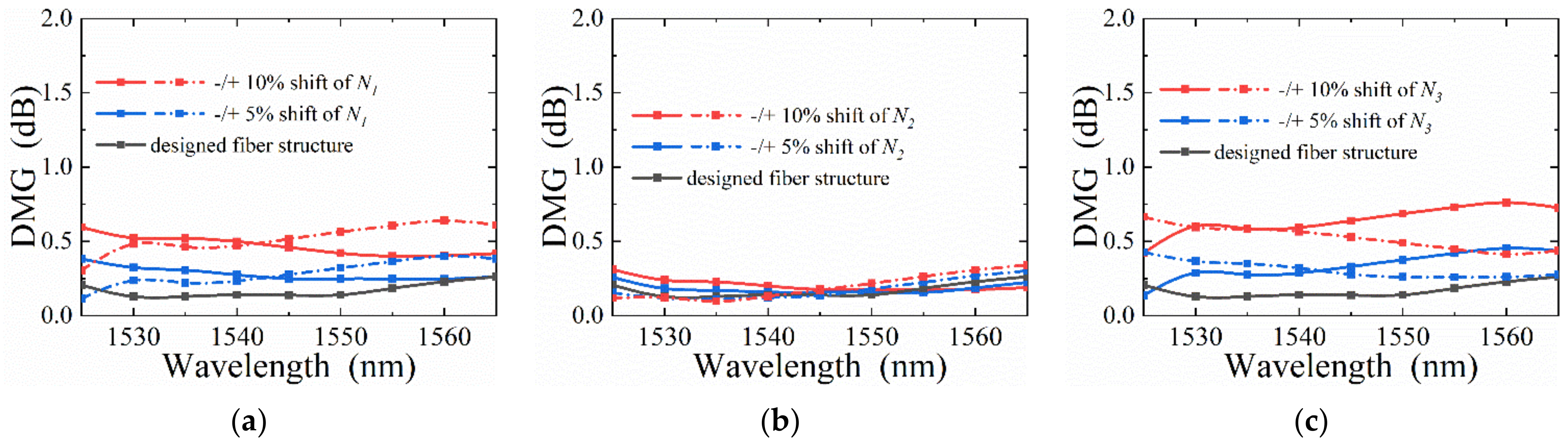
3. Results and Discussions
4. Conclusions
Author Contributions
Funding
Institutional Review Board Statement
Informed Consent Statement
Data Availability Statement
Conflicts of Interest
References
- Wyrowski, F.; Sheridan, J.T.; Tervo, J.; Meuret, Y.; Herbster, A.; Romero, M.A. On the design of few-mode Er-doped fiber amplifiers for space-division multiplexing optical communications systems. In Proceedings of the Optical Modelling and Design III, Brussels, Belgium, 15–17 April 2014. [Google Scholar]
- Desurvire, E.B. Capacity Demand and Technology Challenges for Lightwave Systems in the Next Two Decades. J. Lightwave Technol. 2006, 24, 4697–4710. [Google Scholar] [CrossRef]
- Tkach, R.W. Scaling optical communications for the next decade and beyond. Bell Labs Tech. J. 2010, 14, 3–9. [Google Scholar] [CrossRef]
- Essiambre, R.J.; Mecozzi, A. Capacity Limits in Single-Mode Fiber and Scaling for Spatial Multiplexing. In Proceedings of the Optical Fiber Communication Conference 2012, Los Angeles, CA, USA, 4–8 March 2012; p. OW3D.1. [Google Scholar]
- Ezra Ip, N.B.; Huang, Y.K.; Mateo, E.; Yaman, F.; Li, M.J.; Bickham, S.; Ten, S.; Liñares, J.; Montero, C.; Moreno, V.; et al. 88 × 3 × 112-Gb/s WDM transmission over 50 km of three-mode fiber with inline few-mode fiber amplifier. Proceedings of European Conference and Exposition on Optical Communications 2011, Geneva Switzerland, 18–22 September 2011; p. Th.13.C.12. [Google Scholar]
- Sleiffer, V.A.J.M.; Veljanovski, V.; van Uden, R.G.H.; Kuschnerov, M.; Kang, Q.; Grüner-Nielsen, L.; Sun, Y.; Richardson, D.J.; Alam, S.; Poletti, F.; et al. 73.7 Tb/s (96 × 3 × 256-Gb/s) mode-division-multiplexed DP-16QAM transmission with inline MM-EDFA. In Proceedings of the European Conference and Exhibition on Optical Communication 2012, Amsterdam, The Netherlands, 16–20 September 2012; p. Th.3.C.4. [Google Scholar]
- Sleiffer, V.A.; Leoni, P.; Jung, Y.; Surof, J.; Kuschnerov, M.; Veljanovski, V.; Alam, S.U.; Richardson, D.J.; Gruner-Nielsen, L.; Sun, Y.; et al. 20 × 960-Gb/s Space-division-multiplexed 32QAM transmission over 60 km few-mode fiber. Opt. Express 2014, 22, 749–755. [Google Scholar] [CrossRef] [PubMed][Green Version]
- Ip, E. Gain Equalization for Few-Mode Fiber Amplifiers Beyond Two Propagating Mode Groups. IEEE Photonics Technol. Lett. 2012, 24, 1933–1936. [Google Scholar] [CrossRef]
- Bairagi, R.N.; Roy, A.; Pervin, S.; Sher, S.M. Design of a Concentric Triple-core based Dispersion Compensating Fiber. In Proceedings of the 2019 4th International Conference on Electrical Information and Communication Technology (EICT), Khulna, Bangladesh, 20–22 December 2019. [Google Scholar]
- Gaur, A.; Rastogi, V. Modal gain equalization of 18 modes using a single-trench ring-core EDFA. J. Opt. Soc. Am. B 2018, 35, 2211–2216. [Google Scholar] [CrossRef]
- Jin, C.; Ung, B.; Messaddeq, Y.; LaRochelle, S. Tailored modal gain in a multi-mode erbium-doped fiber amplifier based on engineered ring doping profiles. In Proceedings of the Photonics North 2013, Ottawa, ON, Canada, 3 July 2013; pp. 1–12. [Google Scholar]
- Wada, M.; Sakamoto, T.; Aozasa, S.; Mori, T.; Yamamoto, T.; Hanzawa, N.; Yamamoto, F. L-band 2-LP mode EDFA with low modal dependent gain. In Proceedings of the 2015 Optical Fiber Communications Conference and Exhibition (OFC), Los Angeles, CA, USA, 22–26 March 2015. [Google Scholar]
- Jung, Y.; Kang, Q.; Sleiffer, V.A.; Inan, B.; Kuschnerov, M.; Veljanovski, V.; Corbett, B.; Winfield, R.; Li, Z.; Teh, P.S.; et al. Three mode Er3+ ring-doped fiber amplifier for mode-division multiplexed transmission. Opt. Express 2013, 21, 10383–10392. [Google Scholar] [CrossRef] [PubMed]
- Jung, Y.; Alam, S.; Li, Z.; Dhar, A.; Giles, D.; Giles, I.P.; Sahu, J.K.; Poletti, F.; Grüner-Nielsen, L.; Richardson, D.J. First demonstration and detailed characterization of a multimode amplifier for space division multiplexed transmission systems. Opt. Express 2011, 19, B952–B957. [Google Scholar] [CrossRef] [PubMed]
- Kang, Q.; Gregg, P.; Jung, Y.; Lim, E.L.; Alam, S.U.; Ramachandran, S.; Richardson, D.J. Amplification of 12 OAM Modes in an air-core erbium doped fiber. Opt. Express 2015, 23, 28341–28348. [Google Scholar] [CrossRef] [PubMed]
- Bai, N.; Wang, T.; Li, G. Multimode fiber amplifier with tunable modal gain using a reconfigurable multimode pump. Opt. Express 2011, 19, 16601–16611. [Google Scholar] [CrossRef] [PubMed]
- Kasahara, M.; Saitoh, K.; Sakamoto, T.; Hanzawa, N.; Matsui, T.; Tsujikawa, K.; Yamamoto, F. Design of Three-Spatial-Mode Ring-Core Fiber. J. Lightwave Technol. 2014, 32, 1337–1343. [Google Scholar] [CrossRef]
- Yung, Y.; Alam, S.; Li, Z.; Dhar, A.; Giles, D.; Giles, I.; Sahu, J.; Grűner-Nielsen, L.; Poletti, F.; Richardson, D.J. First demonstration of multimode amplifier for spatial division multiplexed transmission systems. In Proceedings of the 37th European Conference and Exposition on Optical Communications, Geneva, Switzerland, 18 September 2011; p. Th.13.K.14. [Google Scholar]
- Ono, H.; Hosokawa, T.; Ichii, K.; Matsuo, S.; Nasu, H.; Yamada, M. 2-LP mode few-mode fiber amplifier employing ring-core erbium-doped fiber. Opt. Express 2015, 23, 27405–27418. [Google Scholar] [CrossRef] [PubMed]
- Jung, Y.; Kang, Q.; Shen, L.; Chen, S.; Wang, H.; Yang, Y.; Shi, K.; Thomsen, B.C.; Correa, R.A.; Eznaveh, Z.S.; et al. Few Mode Ring-Core Fibre Amplifier for Low Differential Modal Gain. In Proceedings of the 2017 European Conference on Optical Communication (ECOC), Gothenburg, Sweden, 17–21 September 2017; pp. 1–3. [Google Scholar]
- Gregg, P.; Kristensen, P.; Ramachandran, S. Conservation of orbital angular momentum in air-core optical fibers. Optica 2015, 2, 267–271. [Google Scholar] [CrossRef]
- Ye, J.; Li, Y.; Han, Y.; Deng, D.; Guo, Z.; Gao, J.; Sun, Q.; Liu, Y.; Qu, S. Excitation and separation of vortex modes in twisted air-core fiber. Opt. Express 2016, 24, 8310–8316. [Google Scholar] [CrossRef] [PubMed]
- Gregg, P.; Kristensen, P.; Golowich, S.E.; Olsen, J.Ø.; Steinvurzel, P.; Ramachandran, S. Stable Transmission of 12 OAM States in Air-Core Fiber. In Proceedings of the CLEO: Science and Innovations 2013, San Jose, CA, USA, 9–14 June 2013; p. CTu2K.2. [Google Scholar]
- Yamashita, Y.; Matsui, T.; Wada, M.; Aozasa, S.; Sakamoto, T.; Nakajima, K. Differential Modal Gain Reduction using a Void Inscribed in a Two-Mode-Erbium Doped Fiber. In Proceedings of the Optical Fiber Communication Conference 2020, San Diego, CA, USA, 8–12 March 2020; p. W4B.6. [Google Scholar]
- Jung, Y.; Kang, Q.; Sidharthan, R.; Ho, D.; Yoo, S.; Gregg, P.; Ramachandran, S.; Alam, S.-U.; Richardson, D.J. Optical Orbital Angular Momentum Amplifier Based on an Air-Hole Erbium-Doped Fiber. J. Lightwave Technol. 2017, 35, 430–436. [Google Scholar] [CrossRef]
- Krummrich, P.M.; Akhtari, S. Selection of energy optimized pump concepts for multi core and multi mode erbium doped fiber amplifiers. Opt. Express 2014, 22, 30267–30280. [Google Scholar] [CrossRef] [PubMed]
- Kang, Q.; Lim, E.L.; Jung, F.P.; Baskiotis, C.; Alam, S.U.; Richardson, D.J. Minimizing differential modal gain in cladding-pumped EDFAs supporting four and six mode groups. Opt. Express 2014, 22, 21499–21507. [Google Scholar] [CrossRef] [PubMed]
- Kang, Q.; Lim, E.-L.; Poletti, F.; Jung, Y.; Alam, S.-u.; Richardson, D.J. Minimizing Differential Modal Gain in Cladding Pumped MM-EDFAs for Mode Division Multiplexing in C and L Bands. In Proceedings of the International Photonics and OptoElectronics Meetings, Wuhan, China, 18–21 June 2014; p. FTh4F.1. [Google Scholar]
- Chang, J.H.; Corsi, A.; Rusch, L.A.; LaRochelle, S. Design Analysis of OAM Fibers Using Particle Swarm Optimization Algorithm. J. Lightwave Technol. 2020, 38, 846–856. [Google Scholar] [CrossRef]
- Le Cocq, G.; Quiquempois, Y.; Bigot, L. Optimization Algorithm Applied to the Design of Few-Mode Erbium Doped Fiber Amplifier for Modal and Spectral Gain Equalization. J. Lightwave Technol. 2015, 33, 100–108. [Google Scholar] [CrossRef]
- Chu, T.; Wang, P.; Zhu, C. Modeling of Active Fiber Loop Ring-Down Spectroscopy Considering Gain Saturation Behavior of EDFA. J. Lightwave Technol. 2020, 38, 966–973. [Google Scholar] [CrossRef]


Publisher’s Note: MDPI stays neutral with regard to jurisdictional claims in published maps and institutional affiliations. |
© 2022 by the authors. Licensee MDPI, Basel, Switzerland. This article is an open access article distributed under the terms and conditions of the Creative Commons Attribution (CC BY) license (https://creativecommons.org/licenses/by/4.0/).
Share and Cite
Li, Z.; Pei, L.; Zheng, J.; Wang, J.; Xu, W.; Ning, T.; Li, J. A Multi-Layer Erbium-Doped Air-Hole-Assisted Few-Mode Fiber with Ultra-Low Differential Modal Gain. Photonics 2022, 9, 305. https://doi.org/10.3390/photonics9050305
Li Z, Pei L, Zheng J, Wang J, Xu W, Ning T, Li J. A Multi-Layer Erbium-Doped Air-Hole-Assisted Few-Mode Fiber with Ultra-Low Differential Modal Gain. Photonics. 2022; 9(5):305. https://doi.org/10.3390/photonics9050305
Chicago/Turabian StyleLi, Zhiqi, Li Pei, Jingjing Zheng, Jianshuai Wang, Wenxuan Xu, Tigang Ning, and Jing Li. 2022. "A Multi-Layer Erbium-Doped Air-Hole-Assisted Few-Mode Fiber with Ultra-Low Differential Modal Gain" Photonics 9, no. 5: 305. https://doi.org/10.3390/photonics9050305
APA StyleLi, Z., Pei, L., Zheng, J., Wang, J., Xu, W., Ning, T., & Li, J. (2022). A Multi-Layer Erbium-Doped Air-Hole-Assisted Few-Mode Fiber with Ultra-Low Differential Modal Gain. Photonics, 9(5), 305. https://doi.org/10.3390/photonics9050305