Abstract
The optical phase conjugation (OPC) process is thoughtfully investigated in a nonlinear bidirectional semiconductor optical amplifier subsystem (SOA), demonstrating the conjugation conversion through the two ports of the SOA, simultaneously. The spectral responses, the nonlinear power curves and the quality optimization of the conjugated are discussed through the simulation in nonlinear bidirectional configuration. The experimental investigation of the polarization-insensitive SOA further confirms the OPC behavior in the bidirectional operation, achieving the error-free conjugation conversion with an output optical signal-to-noise ratio (OSNR) of up to 16 dB. The nonlinear bidirectional SOA configuration tested in the system relaxes the requirement of the conventional four-wave mixing (FWM), enabling the OPC conversion with the signal regeneration in only one unit.
1. Introduction
With the exponential growth on the transmission rate of the optical fiber communication networks, the technologies significantly increasing the system capacity, e.g., advanced modulation formats or ultra-high-density multiplexing, have been implemented into the real transmission system [1]. However, such a system becomes more vulnerable due to the higher requirement on the optical signal-to-noise ratio (OSNR), whose performance is sensitive to the accumulated amplifier spontaneous emission (ASE) noise, the fiber dispersion, or the Kerr effect-induced nonlinear distortions [2,3,4]. This situation becomes even worse for long-haul transmission operations [5]. To improve the system performance, great efforts through proposing novel approaches have been carried out for decades. These methods can be categorized into two groups: one is to deal with the distortions in the electrical domain at the receiver end; and the other is implemented into the middle of the transmission link directly in the optical domain. For the compensation algorithm in the electrical domain, it was successfully utilized at the commercial receiver, which could compensate the distortions from the fiber dispersion or even the Kerr nonlinearity [6,7]. However, for the application into the transmission link, the optical processing method is more attractive because of no extra energy-hungry, complex optical-electrical-optical (O/E/O) processes implemented in such schemes [8,9]. Therefore, this paper focuses on the signal processing directly in the optical domain.
The signal’s distortions could be mitigated directly in the optical domain through all-optical regenerators [10] or the compensation schemes, e.g., the optical phase conjugator (OPC) [9]. The OPC is more suitable to be implemented into the transmission link when dealing with the deterministic distortions that originated from the fiber dispersion or the Kerr nonlinearity, without implementing the amplitude or phase matching processes that have to be carefully performed in the regenerators, especially for the multi-level modulation formats [11]. Multiple functions, e.g., the wavelength-shift free processes [12] or the cascaded inline operation [13] were performed through OPC supporting the high-capacity, long-haul transmission. The OPC function has been demonstrated through a variety of nonlinear optical devices, such as the highly nonlinear fiber [11], the silicon waveguide [14], the periodically poled lithium niobate (PPLN) [15], or the semiconductor optical amplifier (SOA) [16]. Highly launched optical power is naturally expected in the passive devices because more pump is required to stimulate the nonlinear process. However, multiple effects, e.g., the stimulated Brillouin scattering (SBS) in fibers [17] or the two-photon absorption (TPA) in silicon waveguides [18], introducing the nonlinear losses into the optical devices, dramatically reduce the effectively launched power and also increase the complexity of such systems by adopting additional approaches to mitigate their impacts. By contrast, the low launched power is required in the active SOA, only microwatt or even lower power for the most of cases, bypassing the high-power pump injection issue. Therefore, the active SOA-based OPC subsystem is more suitable to be implemented into the real transmission systems.
SOA-based signal processing was extensively discussed when the conventional on-off keying (OOK) data formats were widely used in the optical fiber communication networks. The nonlinear interferometer configurations performed by several SOA units could demonstrate the functions of the date conversion [19], the signal regeneration [20], or the nonlinear gate [21]. These nonlinear-optical loop mirrors (NOLMs) or the Mach–Zehnder interferometers (MZIs) are more sensitive to the environment factors, such as the temperature or the vibration. Therefore, the nonlinear process that only happen in one SOA unit is more attractive. The signal processing in such systems performed amplitude regeneration for OOK [22] or quadrature phase-shift keying (QPSK) signals [23,24] through the conventional optical parametric processes. A novel scheme by using a bidirectional SOA configuration was proposed, in which the four-wave mixing (FWM) process between pump and signal not only happened at the co-propagating directions, but also at the opposite direction where there was no signal launched [25]. In this paper, we focus on the pump selection and the consequent OPC behaviors in the nonlinear bidirectional SOA configuration by simulation and experiment. The discussion on the conjugated conversion of QPSK signals helps to locate the optimized operation of advanced modulation formats for the modern optical fiber communication systems.
In this work, we report a thoughtful investigation on the OPC performance in the nonlinear bidirectional SOA configuration, and its impacts on both the amplitude and phase of input signals. The content is extended from our previous works [26] and organized as follows: In Section 2, we carry out the numerical simulation for all four cases of the launched pump-x-polarized forward (XF), y-polarized backward (YB), y-polarized forward (YF), and x-polarized backward (XB); in Section 3 we experimentally demonstrate the OPC process in only one bidirectional SOA and discuss the obtained QPSK results from both the amplitude and phase information; in Section 4, the discussion on the OPC and the amplitude noise suppression is carried out for the proposed scheme; we summarize our results in Section 5.
2. Numerical Simulation
The SOA considered in our OPC subsystem is an active optical device, which supports the nonlinear response in the bidirectional operation, depicted in Figure 1. In such nonlinear unit, the bidirectionally injected pump P could perform the nonlinear mixing behavior through FWM with the single-launched signal S, obtaining the OPC products from the two ports of SOA at the same time [25]. This process is also related to the polarization of the input pump and signal. Therefore, two groups including four cases, i.e., pump-XF, -YB, -YF, and -XB are considered in the proposed OPC subsystem. Although the signal is only inputted from the single port, i.e., the input port, the OPC products could be collected from both the input and output ports, relaxing the requirement of the conventional FWM, which expects the co-propagating direction between pump and signal to satisfy the phase-matching condition.
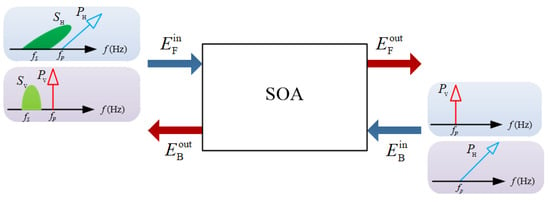
Figure 1.
Schematic diagram of the OPC process based on a nonlinear bidirectional SOA.
Based on the principle of the nonlinear bidirectional SOA-based OPC process, we set up the simulation platform in VPI, the system depicted in Figure 2. The simulation system includes three parts: the QPSK transmitter, the OPC subsystem, and the coherent receiver. In the transmitter, the optical QPSK signal was generated through an IQ modulator. The continuous-wave (CW) light with the frequency of 193.0 THz was injected into the IQ modulator, which was driven by the electrical signals from an arbitrary waveform generator (AWG). Then, the obtained optical QPSK signal was amplified by an Erbium-doped fiber amplifier 1 (EDFA1) and launched into a “Set OSNR” unit to load the ASE noise, which was used to evaluate the impact from the cascaded EDFAs as the real implementation. The bandpass filter 1 (BPF1) with the bandwidth of 0.32 nm was utilized to block the ASE noise from the outside band. At the output of the transmitter, we obtained the degraded QPSK signals with a defined OSNR.
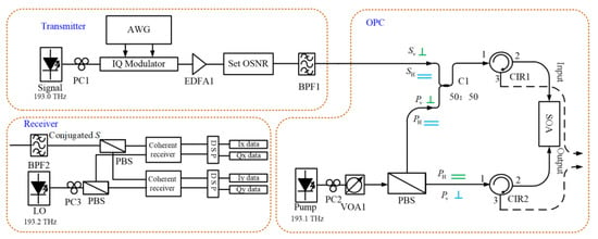
Figure 2.
Simulation setup of the nonlinear bidirectional SOA-based OPC process.
The nonlinear bidirectional SOA-based OPC subsystem is the key to the test platform. The model of SOA used in the simulation was “SOA_TLM” in VPI. The main parameters were: the length of the device section was 6.33 × 10⁻⁴ m, the nonlinear index was 6.2 × 10⁻¹⁹ m2/W, and the effective mode area was 10−12 m2. The bidirectionally injected pump was generated by a CW light source, with a frequency of 193.1 THz located at the channel C31 in the wavelength division multiplexing (WDM) grid. According to the phase-matching condition of the FWM process, the OPC product could be observed at the frequency of 193.2 THz, also located at the WDM grid-channel C32. The CW pump was firstly split by a polarization beam splitter (PBS) into the two equal-power parts with orthogonal state-of-polarizations (SOPs) PH and PV. The optical power and SOP of the pump were adjusted by the polarization controller 2 (PC2) and the variable optical attenuator 1 (VOA1). Then, the two orthogonal pumps were launched into the bidirectional SOA from the input and output port, respectively. The other input was the QPSK signal SV or SH, in which SOP was controlled by a PC1 to make an alignment to the upper component of the pump. The QPSK with the data rate of 20 Gb/s was only injected from the forward direction through the input-port into the bidirectional SOA. However, the FWM process and the consequent OPC product could be observed by the two ports of SOA, simultaneously. Two optical circulators (CIRs) were placed at the input and output port of SOA to separate all of the FWM products from the opposite inputs.
At the coherent receiver, the OPC product S was selected by a BPF2 with the bandwidth of 0.32 nm. The conjugated signal was launched into the dual-polarization coherent receiver, which could not only detect the QPSK signals, but also monitor its polarization property. The local oscillator (LO) with the frequency of 193.2 THz, the same as the conjugated input, was injected into the receiver from LO port, in which SOP was adjusted by PC3 to make the best coherent detection. The electrical data were further processed by the digital signal processing (DSP) algorithms to perform the basic compensation, including the functions of compensating phase noise and equalizing the linear crosstalk between symbols.
The nonlinear bidirectional SOA scheme could support two types of the allocation for the pump, the two orthogonally linearly-polarized components x or y propagating through the upper or lower arms, respectively. See the symbols of the parallel “═” and the vertical “┴” in the OPC subsystem of Figure 2. Because the FWM process happened for both directions, the OPC products were collected from the output port and the input port, simultaneously. For the results obtained from output port, the conjugated was generated by the nonlinear mixing between the upper-arm pump and the input signal; while, the conjugated result from input port was the product between the lower-arm pump and the counter-propagating input signal. Therefore, we have a total of four OPC products from the two groups: group one—XF with YB; and group two—YF with XB. In what follows, we focus on the OPC processes for the four cases.
2.1. OPC in Group One: XF and YB Cases
We adjusted the PC1 and PC2 to restrict the signal and the forward upper-pump component at x-polarization and the corresponding FWM spectrum was observed at the port 3 of CIR2 as depicted in Figure 3a. This is the conventional FWM behavior, which contains the co-propagating pump and signal. Not only the conjugated component was obtained, but also the high-order FWM products observed in this case. We kept the forward pump power as 0 dBm and swept the signal power, obtaining the relationship between the conjugated power and the pump-to-signal ratio (PSR) in Figure 3b. The PSR is critical to the operation of the SOA in the all-optical signal processing [24], which could suppress the pattern effect through the constant optical power, i.e., the CW pump in our case. In Figure 3b, only one plateau region was observed when increasing the input PSR, the peak power obtained at PSR= 2 dB. In the view of the signal regeneration, the best quality of the obtained conjugation should be achieved in this region, because both the OPC and the amplitude noise suppression were performed at the same time. We further monitored the signal quality through SNR for different input PSRs, results depicted in Figure 3c. The highest SNR obtained by the conjugated was 18.02 dB at PSR = 1 dB, slightly shifting from the peak power point, which was 3.25 dB SNR gain compared to the input signal (SNR = 14.77 dB). The constellation results from the input and the conjugated signals confirmed the OPC performance. We also obtained the region from PSR = −4 dB to 11 dB, where the conjugated production has better signal quality compared to the input. From the collections of the dual-polarization coherent receiver, the conjugated power was −3.1 dBm mainly in x-polarization (only −21.5 dBm in y-polarization), so the SOP of the conjugated obtained in the XF case is the same as the input signal. To reveal the details of the conjugation process, the amplitude and phase responses were calculated in Figure 3d,e. For the amplitude case, only the information from the amplitude domain was considered in the calculation, and the gain of the error vector magnitude in amplitude (EVM|Amp) was plotted in Figure 3d. The larger PSR range from −7 dB to 11 dB was obtained for the amplitude only case. The best amplitude noise suppression happened at PSR= −1 dB where the best improvement of ΔEVM|Amp = 5 dB compared to the input was obtained. The phase results, quantified by the EVM|Pha, were depicted in Figure 3e. Although the flatter response was obtained in the phase only case, a narrow PSR range from −1 dB to 10 dB was observed through the calculation. Therefore, the OPC in the XF case performs the conjugated conversion with the property of the signal regeneration in the selected operational region.
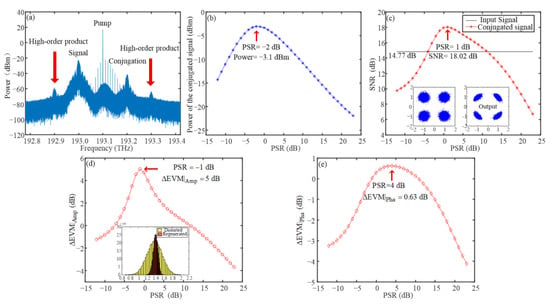
Figure 3.
(a) Optical spectrum obtained in the XF case; (b) power response of the conjugated signal with the input PSR; (c) signal quality of the conjugated results with the PSR; (d) the amplitude EVM gain ΔEVM|Amp; and (e) the phase EVM gain ΔEVM|Pha on the input PSR.
When the XF case happened by tuning the PCs in both the pump and the signal arms, the OPC product in YB case was naturally collected through port 3 of CIR1 because the PBS placed at the pump arm maintained the orthogonal states between two counter-propagating components. The optical spectrum depicted in Figure 4a confirms the FWM process indeed happened, although in the backward direction the large phase-mismatching was expected. This physical phenomenon relaxes the requirement of the conventional FWM, which also performs the unique nonlinear response as follows. Figure 4b gives the optical power of the conjugated vs. the input PSR. Two power plateau regions were obtained in this case. In the view of the signal regeneration, the amplitude noise could be suppressed at both regions. However, the higher PSR gives the better pattern-effect suppression in SOA. Therefore, the second plateau around PSR = 2 dB should perform with better conversion quality. The conjugated signal measured through SNR in Figure 4c confirms the prediction, the best output SNR = 16.34 dB obtained at PSR = 2 dB. We also plot the constellations before and after the YB-OPC process. The amplitude noise suppression is obviously observed, which proves the OPC as well as the signal regeneration simultaneously happened. The amplitude and phase responses are depicted in Figure 4d,e. Two amplitude-regeneration regions were obtained corresponding to the two plateaus. The most sufficient suppression was achieved at the second plateau, the best improvement of ΔEVM|Amp = 1.6 dB was obtained in this region. The results from the phase response confirm that the lesser impact on the signal’s phase happened in the YB-OPC process in the PSR range of 17 dB.
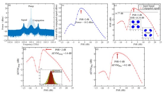
Figure 4.
(a) Optical spectrum in the YB case; (b) power curve of the conjugated signal with PSR; (c) relation between SNR and PSR; (d) the amplitude EVM gain ΔEVM|Amp; and (e) the phase EVM gain ΔEVM|Pha on the input PSR.
Although the XF- and YB-OPC processes happened at the same time in the nonlinear bidirectional SOA, the FWM response and the OPC product are clearly different for both cases. The lesser OPC efficiency is obtained for the backward pump, i.e., YB-OPC, only −10.2 dBm maximum output power obtained compared to −3.1 dBm for the XF case. The different nonlinear response also leads to the different quality of the obtained conjugation. However, the OPC with the signal regeneration was demonstrated for both nonlinear processes.
2.2. OPC in Group Two: YF and XB Cases
We tuned PC1 and PC2 to investigate the OPC process for the YF and XB cases. For the YF-OPC, which was the co-propagating upper-arm pump and signal with y-polarization, we collected the optical spectrum of the FWM through port 3 of CIR2, depicted in Figure 5a. The similar response including the OPC and the high-order FWM products was obtained as XF-OPC because of the polarization-insensitive SOA used in the simulation. This SOA demonstrates the polarization-insensitive performances not only on the optical amplification, but also for the nonlinear response. The single power plateau as well as the SNR improvement of 3.27 dB are the same as the XF-OPC case. The amplitude and phase responses of the conjugated depicted in Figure 5d,e suggest the amplitude noise suppression with the property of the phase-preserving operation happened in the YF-OPC process, also similar to the XF-OPC.
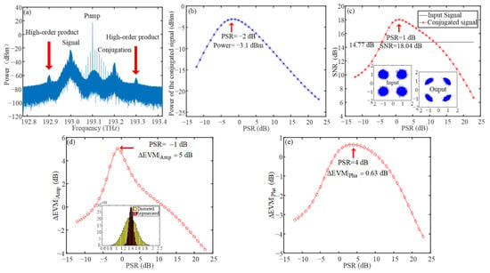
Figure 5.
(a) Spectrogram in YF case; (b) power curve of the conjugated signal with PSR; (c) relation between SNR and PSR; (d) the amplitude EVM gain ΔEVM|Amp; and (e) the phase EVM gain ΔEVM|Pha on the input PSR.
Figure 6 depicts the simulation results for XB-OPC, which were collected from port 3 of CIR1. Two power plateau regions were obtained as the YB-OPC. However, the best performance was only achieved at the second plateau where PSR = 2 dB. The lesser amplitude noise suppression obtained in the XB-OPC only produced 1.59 dB for SNR gain and ΔEVM|Amp = 1.6 dB, which suggests the signal quality improvement mainly happened in the amplitude domain. The nonlinear response from the XB-OPC case is also the same as the YB-OPC due to the polarization-insensitive property of the used SOA.
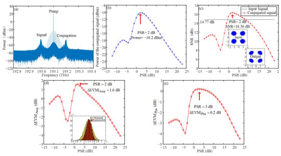
Figure 6.
(a) Spectrogram in XB case; (b) power curve of the conjugated signal with (PSR); (c) relation between SNR and PSR; (d) the amplitude EVM gain ΔEVM|Amp; and (e) the phase EVM gain ΔEVM|Pha on the input PSR.
3. Experimental Investigation
To investigate the OPC performance in the nonlinear bidirectional SOA, we set up the experimental platform in Figure 7, just as the simulation configuration of Figure 2. The key device nonlinear SOA coming from the CIP (SOA-NL-OEC-1550) performed the bidirectional, polarization-insensitive operation in the experiment. The main parameters of the tested SOA were: the polarization-dependent saturated gain (PDG) was 0.5 dB, the saturated output power was 6 dBm, and the saturated gain recovery time was 25 ps. Two types of input signal were launched into the OPC subsystem separately, which were the CW light and the QPSK signal. The CW light was used to test the OPC process and the conversion efficiency, and the QPSK was to monitor the signal quality of the conjugated products. The wavelength of the input signal was 1548.52 nm. The data rate of the input QPSK was 5 Gb/s. The bidirectionally injected pump was generated by a CW source, with a wavelength of 1547.81 nm. The optical power of the pump was from −10 dBm to 0 dBm, which was limited by the maximum input requirement of the SOA. In the experiment, we used the PC2 to align the input SOP of the pump with the PBS, to make sure that equal pump power was split into the two outputs with the orthogonal SOP. To monitor the SOP of the input signal, a polarization analyzer (PA) was connected to the other output port of the coupler C1. The same SOP between the upper-arm pump and the signal was achieved through adjusting the PC1 placed at the signal arm. The two VOAs (VOA1 and VOA2) were used to sweep the launched optical powers, to measure the power dependency of the nonlinear responses. The OPC spectrum or the conjugated product were detected by the optical spectrum analyzer (OSA) or the coherent receiver. There are still four OPC cases obtained in the nonlinear bidirectional SOA system as the previous discussion. However, for a polarization-insensitive SOA, the tested results from the two group are the same. Therefore, we focus on the first group, i.e., XF and YB cases to carry out the detail measurements, including the spectral response, the conversion efficiency, and the conjugated signals.
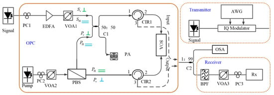
Figure 7.
Experiment setup of the nonlinear bidirectional SOA-based OPC process.
3.1. OPC in XF
In the XF case, the SOPs of the upper-arm pump and the signal are the x-linearly-polarized mode through tuning PC1 and PC2 in the signal and pump arms, respectively. For the CW test scenario, in which both pump and signal were CW light, we obtained the FWM spectrum from port 3 of CIR2, depicted in Figure 8a. A similar spectral property, including the OPC product and the high-order FWM component, was achieved in the experiment as the simulation result in Figure 3a. Around −20 dB signal-to-conjugation conversion efficiency was obtained in both experiment and theory, which confirmed the OPC behavior in the nonlinear bidirectional SOA.
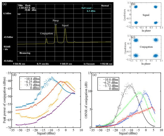
Figure 8.
The result of the experiment in XF case; (a) spectrum; constellation results of input signal (b) and the conjugated signal (c); (d) power transfer function; (e) OSNR curve. (dots: experimental data; solid: fitting curve).
To further reveal the power dependency of the nonlinear response, we carried out the measurement on the optical power of the conjugation vs. the input signal, depicted in Figure 8d. Clearly, the power plateau region was demonstrated for the different pump cases, i.e., −10.8 dBm, −6.25 dBm, −3.72 dBm, and 0 dBm, just as the prediction in the simulation of Figure 3b. With the increase of the pump power, the saturated launched power where the maximum output was achieved was shifted to the higher input, and the corresponding maximum output was also decreased. Based on the tested data, we monitor the OSNR results of the obtained conjugation in Figure 8e. The OSNR was defined by the power difference between the conjugation and the noise floor tested in OSA. The maximum OSNR of the conjugated signal was around 12.23 dB measured in the experiment, also located at the power plateau region.
We also monitored the conjugated signal when a QPSK signal was launched. The constellation results before and after the OPC process are depicted in Figure 8b,c. Clearly, the conjugation conversion was achieved in the tested XF case, but the penalty in the view of the signal quality was also performed. The amplitude regeneration predicted in the simulation section was indeed achieved in our test [27], however, it required the optimization operation on the input OSNR. A detailed discussion on the phase-preserving amplitude regeneration is carried out in the following section.
3.2. OPC in YB
When the XF case was achieved, the results from the YB case were naturally collected from port 3 of CIR1. Figure 9a depicts the FWM spectrum from the YB case, which is similar to the simulation result in Figure 4a. Around −10 dB signal-to-conjugation conversion efficiency was achieved in both the experiment and simulation. We swept the optical power of the input signal and obtained the power dependency between the input signal and the obtained conjugation; see Figure 9d. Four pump cases, i.e., −10 dBm, −8 dBm, −6 dBm, and −4 dBm, perform similar nonlinear responses, and the maximum value of the saturated launched-power is required by the −4 dBm pump case. We also calculated the slope value of the nonlinear curve to confirm two plateau regions obtained in the YB case as the prediction from the simulation, see the labels in Figure 9d. Furthermore, we obtained the OSNR results of the conjugated signal, depicted in Figure 9e. The maximum OSNR obtained in the experiment was 16 dB, suggesting the potential high-quality conjugation conversion. We also plotted the constellation results before and after the OPC process. The error-free conversion was obviously achieved through the clear constellation.
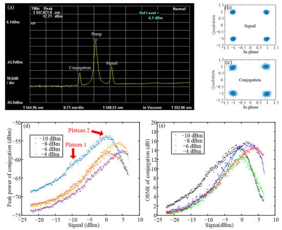
Figure 9.
The result of the experiment in YB case; (a) spectrum; constellation results of input signal (b) and the conjugated signal (c); (d) power transfer function; (e) OSNR curve. (dots: experimental data; solid: fitting curve).
4. Discussion
For the OPC performance, the proposed nonlinear bidirectional SOA configuration not only generates more conjugated products from both the input and output ports, but also reduces the requirement of the PSR level. According to the investigation results, the PSR around 2 dB is high enough to perform the OPC function, which reduces 10 dB compared to the conventional single-pump scheme [24]. The low PSR value allows more signal power to be launched into the SOA unit, consequently increasing the power level of the conjugated product. For the OPC applications, the high conversion efficiency helps to achieve better signal quality due to the higher OSNR.
For the regeneration behavior in the proposed OPC process, according to the simulation results about the nonlinear power responses for the four cases, the power plateau regions were observed, see Figure 3b, Figure 4b, Figure 5b and Figure 6b. Therefore, the amplitude noise suppression also happened when the signal’s amplitude fell into the plateau. This is the main reason why the amplitude regeneration could be achieved in the proposed OPC process. For the signal’s phase, the nonlinear OPC only preserves the initial phase information instead of performing the phase regeneration, which was confirmed by the simulation results in the phase responses of Figure 3e, Figure 4e, Figure 5e and Figure 6e. The different responses on the signal’s amplitude and phase lead to only amplitude noise suppression that happened in the OPC process, which is also called phase-preserving amplitude regeneration.
Although the amplitude regeneration could be achieved by both the forward and backward OPC processes, the different performances were observed, i.e., the maximal amplitude-noise suppression in the forward direction up to 5 dB compared to only 1.6 dB obtained in the backward direction. The diversity comes from the nonlinear power responses, as seen in the results in Figure 3b and Figure 4b. The plateau achieved in the forward direction is much wider than the backward direction, which leads to the higher noise-handling capability. Therefore, the better performance on the amplitude regeneration is achieved in the forward case.
It should be noted that the amplitude-noise suppression is only achieved at the plateau region. When the input power of the signal is away from the plateau, the conventional conjugation-conversion is demonstrated, just as the experimental results depicted in Figure 8c and Figure 9c. The details on the phase-preserving amplitude regeneration will be discussed in the following investigation.
5. Conclusions
We thoughtfully investigated the OPC process in a nonlinear bidirectional SOA configuration. The detail responses, including the optical spectra, the dependencies of the conjugated power, and the signal quality on the input PSRs were discussed through the simulation in the two group cases, i.e., XF + YB and YF + XB. The same results were obtained from the two groups because of the polarization-insensitive characteristic of the tested SOA. We also carried out the experimental measurement on the proposed subsystem, achieving the FWM response at both the input and output port of the SOA. The OPC process in the XF + YB group demonstrated the error-free conjugation conversion and the maximum OSNR of 16 dB obtained in the experiment.
Author Contributions
Conceptualization, F.S. and F.W.; methodology F.S. and F.W.; software, F.S.; validation, F.S. and F.W.; formal analysis, F.S. and F.W.; investigation F.S. and F.W.; resources, F.W., Y.L., B.W. and K.Q.; data curation, F.S.; writing—original draft preparation, F.S.; writing—review and editing, F.W.; visualization, F.S. and F.W.; supervision, F.W., B.W. and K.Q.; project administration, F.W., B.W. and K.Q.; funding acquisition, F.W., B.W. and K.Q. All authors have read and agreed to the published version of the manuscript.
Funding
This work was supported by the National Natural Science Foundation of China (NSFC) (61975027, 61671108) and Sichuan Science and Technology Program (2021YFG0143).
Institutional Review Board Statement
Not applicable.
Informed Consent Statement
Not applicable.
Data Availability Statement
No new data were created or analyzed in this study. Data sharing is not applicable to this article.
Acknowledgments
The authors thank Lukasz Krzczanowicz from DTU and Mingming Tan from Aston University for the valuable discussions on SOA.
Conflicts of Interest
The authors declare no conflict of interest.
References
- Winzer, P.J.; Essiambre, R.-J. Advanced Modulation Formats for High-Capacity Optical Transport Networks. J. Lightwave Technol. 2006, 24, 4711–4728. [Google Scholar] [CrossRef]
- Gordon, J.P.; Mollenauer, L.F. Phase noise in photonic communications systems using linear amplifiers. Opt. Lett. 1990, 15, 1351–1353. [Google Scholar] [CrossRef] [PubMed]
- Jensen, J.B. XPM-induced degradation of multilevel phase modulated channel caused by neighboring NRZ modulated channels. In Proceedings of the 2008 Optical Fiber Communications Conference (OFC), San Diego, CA, USA, 24–28 February 2008. [Google Scholar]
- Ellis, A.D.; Zhao, J.; Cotter, D. Approaching the Non-Linear Shannon Limit. J. Lightwave Technol. 2010, 28, 423–433. [Google Scholar] [CrossRef] [Green Version]
- Johannisson, P.; Agrell, E. Modelling of nonlinear signal distortion in fiber optic networks. J. Lightwave Technol. 2014, 32, 4544–4552. [Google Scholar] [CrossRef] [Green Version]
- Ip, E.; Kahn, J.M. Compensation of Dispersion and Nonlinear Impairments Using Digital Backpropagation. J. Lightwave Technol. 2008, 26, 3416–3425. [Google Scholar] [CrossRef]
- Zhang, S.; Yaman, F.; Nakamura, K.; Inoue, T.; Kamalov, V.; Jovanovski, L.; Vusirikala, V.; Mateo, E.; Inada, Y.; Wang, T. Field and lab experimental demonstration of nonlinear impairment compensation using neural networks. Nat. Commun. 2019, 10, 3033. [Google Scholar] [CrossRef]
- Phillips, I.D.; Tan, M.; Stephens, M.F.C.; McCarthy, M.E.; Giacoumidis, E.; Sygletos, S.; Rosa, P.; Fabbri, S.; Le, S.T.; Kanesan, T.; et al. Exceeding the nonlinear-shannon limit using raman laser based amplification and optical phase conjugation. In Proceedings of the 2014 Optical Fiber Communications Conference (OFC), San Diego, CA, USA, 9–13 March 2014. [Google Scholar]
- Al-Khateeb, M.; Tan, M.; Zhang, T.; Ellis, A.D. Combating Fiber Nonlinearity Using Dual-Order Raman Amplification and OPC. IEEE Photonics Technol. Lett. 2019, 31, 877–880. [Google Scholar] [CrossRef]
- Slavík, R.; Parmigiani, F.; Kakande, J.; Lundström, C.; Sjödin, M.; Andrekson, P.A.; Weerasuriya, R.; Sygletos, S.; Ellis, A.D.; Grüner-Nielsen, L.; et al. All-optical phase and amplitude regenerator for next-generation telecommunications systems. Nat. Photonics 2010, 4, 690–695. [Google Scholar] [CrossRef]
- Yoshima, S.; Sun, Y.; Liu, Z.; Bottrill, K.R.H.; Parmigiani, F.; Richardson, D.J.; Petropoulos, P. Mitigation of Nonlinear Effects on WDM QAM Signals Enabled by Optical Phase Conjugation with Efficient Bandwidth Utilization. J. Lightwave Technol. 2017, 35, 971–978. [Google Scholar] [CrossRef] [Green Version]
- Sackey, I.; Elschner, R.; Schmidt-Langhorst, C.; Kato, T.; Tanimura, T.; Watanabe, S.; Hoshida, T.; Schubert, C. Novel Wavelength-Shift-Free Optical Phase Conjugator Used for Fiber Nonlinearity Mitigation in 200-Gb/s PDM-16QAM Transmission. In Proceedings of the 2017 Optical Fiber Communications Conference (OFC), Los Angeles, CA, USA, 19–23 March 2017. [Google Scholar]
- Hu, H.; Jopson, R.M.; Gnauck, A.H.; Randel, S.; Chandrasekhar, S. Fiber nonlinearity mitigation of WDM-PDM QPSK/16-QAM signals using fiber-optic parametric amplifiers based multiple optical phase conjugations. Opt. Express 2017, 25, 1618–1628. [Google Scholar] [CrossRef] [PubMed] [Green Version]
- Gajda, A.; Da Ros, F.; da Silva, E.P.; Pęczek, A.; Liebig, E.; Mai, A.; Galili, M.; Oxenløwe, L.K.; Zimmerman, L. Silicon Waveguide with Lateral p-i-n Diode for Nonlinearity Compensation by On-Chip Optical Phase Conjugation. In Proceedings of the 2017 Optical Fiber Communications Conference (OFC), San Diego, CA, USA, 11–15 March 2018. [Google Scholar]
- Umeki, T.; Kazama, T.; Sano, A.; Shibahara, K.; Suzuki, K.; Abe, M.; Takenouchi, H.; Miyamoto, Y. Simultaneous nonlinearity mitigation in 92 × 180-Gbit/s PDM-16QAM transmission over 3840 km using PPLN-based guard-band-less optical phase conjugation. Opt. Express 2016, 24, 16945–16951. [Google Scholar] [CrossRef] [PubMed]
- Sobhanan, A.; Karthik, V.A.M.; Narayanan, L.V.; Koilpillai, R.D.; Venkitesh, D. Experimental Analysis of Noise Transfer in Optical Phase Conjugation Process in Nonlinear SOA. In Proceedings of the 2019 Optical Fiber Communications Conference (OFC), San Diego, CA, USA, 3–7 March 2019. [Google Scholar]
- Ippen, E.P.; Stolen, R.H. Stimulated Brillouin scattering in optical fibers. Appl. Phys. Lett. 1972, 21, 539–541. [Google Scholar] [CrossRef]
- Tsang, H.K.; Wong, C.S.; Liang, T.K.; Day, I.E.; Roberts, S.W.; Harpin, A.; Drake, J.; Asghari, M. Optical dispersion, two-photon absorption and self-phase modulation in silicon waveguides at 1.5 μm wavelength. Appl. Phys. Lett. 2002, 80, 416–418. [Google Scholar] [CrossRef]
- Lee, C.G.; Kim, Y.J.; Park, C.S.; Lee, H.J.; Park, C.-S. Experimental Demonstration of 10-Gb/s Data Format Conversions between NRZ and RZ Using SOA-Loop-Mirror. J. Lightwave Technol. 2015, 23, 834–841. [Google Scholar]
- Zhu, Z.; Funabashi, M.; Pan, Z.; Paraschis, L.; Harris, D.L.; Yoo, S.J.B. High-Performance Optical 3R Regeneration for Scalable Fiber Transmission System Applications. J. Lightwave Technol. 2007, 25, 504–511. [Google Scholar] [CrossRef]
- Kim, J.-Y.; Kang, J.-M.; Kim, T.-Y.; Han, S.-K. All-Optical Multiple Logic Gates with XOR, NOR, OR, and NAND Functions Using Parallel SOA-MZI Structures: Theory and Experiment. J. Lightwave Technol. 2006, 24, 3392–3399. [Google Scholar]
- Shao, L.; Wen, F.; Guo, B.; Krzczanowicz, L.; Yang, F.; Wu, B.; Qiu, K. All-optical Amplitude Noise Suppression in a Nonlinear Semiconductor Optical Amplifier (SOA). In Proceedings of the 2020 Asia Communications and Photonics Conference (ACP), Beijing, China, 24–27 October 2020. [Google Scholar]
- Krzczanowicz, L.; Connelly, M.J. 40 Gb/s NRZ-DQPSK Data All-Optical Wavelength Conversion Using Four Wave Mixing in a Bulk SOA. IEEE Photonics Technol. Lett. 2013, 25, 2439–2441. [Google Scholar] [CrossRef]
- Shao, L.; Sun, F.; Wen, F.; Yang, Y.; Yang, F.; Wu, B.; Ling, Y.; Qiu, K. All-optical Amplitude Regeneration of QPSK signals through Optical parametric Process in a Nonlinear SOA. In Proceedings of the 2021 Signal Processing in Photonic Communications (SPPCom), Washington, WA, USA, 26–29 July 2021. [Google Scholar]
- Sobhanan, A.; Venkatasubramani, L.N.; Koilpillai, R.D.; Venkitesh, D. Polarization-Insensitive Phase Conjugation of QPSK Signal Using Bragg-Scattering FWM in SOA. IEEE Photonics Technol. Lett. 2019, 31, 919–922. [Google Scholar] [CrossRef]
- Sun, F.; Wen, F.; Yang, F.; Wu, B.; Ling, Y.; Qiu, K. Optical Phase Conjugation Characterization in a Polarization-Selected Orthogonal Pumped SOA Subsystem. In Proceedings of the 2021 Optoelectronics and Communications Conference (OECC), Hong Kong, China, 3–7 July 2021. [Google Scholar]
- Sun, F.; Wen, F.; Wu, B.; Fan, F.; Ling, Y.; Qiu, K. All-Optical Phase-Preserving Amplitude Regeneration through Optical Phase Conjugation in a Polarization-Selected Orthogonal-Pumped SOA Subsystem. In Proceedings of the 2021 Asia Communications and Photonics Conference (ACP), Shanghai, China, 24–27 October 2021. [Google Scholar]
Publisher’s Note: MDPI stays neutral with regard to jurisdictional claims in published maps and institutional affiliations. |
© 2022 by the authors. Licensee MDPI, Basel, Switzerland. This article is an open access article distributed under the terms and conditions of the Creative Commons Attribution (CC BY) license (https://creativecommons.org/licenses/by/4.0/).