Article

Multi-Way Noiseless Signal Amplification in a Symmetrical Cascaded Four-Wave Mixing Process

1
College of Optical and Electronic Technology, China Jiliang University, Hangzhou 310018, China
2
State Key Laboratory of Precision Spectroscopy, Joint Institute of Advanced Science and Technology, School of Physics and Electronic Science, East China Normal University, Shanghai 200062, China
3
NMPA Key Laboratory for Biomedical Optics, Zhejiang Institute of Medical Device Supervision and Testing, Hangzhou 310018, China
4
CAS Center for Excellence in Ultra-intense Laser Science, Shanghai 201800, China
5
Collaborative Innovation Center of Extreme Optics, Shanxi University, Taiyuan 030006, China
6
Department of Physics, Zhejiang University, Hangzhou 310027, China
*
Author to whom correspondence should be addressed.
Photonics 2022, 9(4), 229; https://doi.org/10.3390/photonics9040229
Submission received: 6 March 2022 / Revised: 28 March 2022 / Accepted: 30 March 2022 / Published: 1 April 2022
(This article belongs to the Special Issue Advances and Application of Optical Manipulation)

Abstract

:
According to the fundamental laws of quantum optics, vacuum noise is inevitably added to the signal when one tries to amplify a signal. However, it has been recently shown that noiseless signal amplification can be realized when a phase-sensitive process is involved. Two phase-sensitive schemes, a correlation injection scheme and a two-beam phase-sensitive amplifier scheme, are both proposed to realize multi-way noiseless signal amplification in a symmetrical cascaded four-wave mixing process. We theoretically study the possibility of the realization of four-way noiseless signal amplification by using these two schemes. The results show that the correlation injection scheme can only realize one-way noiseless signal amplification, but that the two-beam phase-sensitive amplifier scheme can lead to four-way noise figure values below 1. Our results here may find potential applications in quantum information processing, e.g., the realization of quantum information tap and quantum non-demolition measurement, etc.

1. Introduction

Noiseless signal amplification is the ultimate goal of any quantum amplifier. However, for a phase-insensitive amplifier, the quantum noise of vacuum is inevitably coupled in via the unused port [1]. Thus, in the amplification process, the deterioration of the signal-to-noise ratio (SNR) is unavoidable and can be halved in the high gain limit. This is often referred to as the 3 dB penalty for a phase-insensitive amplifier [2,3]. To overcome this penalty, an electro-optic feedforward scheme can be used to produce perfect noiseless signal amplification in the linear optical process [4]. From the perspective of application, a noiseless linear amplifier employed at the stage of signal preparation is a useful resource to enhance the performance of coherent signals in the presence of phase diffusion [5]. In addition, the effect of phase diffusion on quantum communication channels based on phase the modulation of coherent states [6], experimental estimation of one-parameter qubit gates [7], and the implementation of high-precision interferometric measurements [8] has also been investigated thoroughly. Meanwhile, for the nonlinear optical process, a noiseless optical amplifier based on a phase-sensitive four-wave mixing (FWM) process has been implemented, and its noise figure (NF) value is always better than that obtained with a phase-insensitive amplifier with the same gain [9]. Similarly, a probabilistic amplifier as the underlying nonlinear operation can also be used to improve the detection efficiency in the scheme of the detection of a low-intensity optical coherent signal [10]. However, the two above schemes [4,9] are both used to realize the noiseless signal amplification for the one-way case (one input–one output) using a direct intensity detection method.
The FWM process in an atomic vapor cell as a phase-insensitive amplifier can be used to amplify the signal beam, and a new beam called the idler beam is generated on the other side of the pump beam at the same time [11,12,13,14]. In this sense, the FWM process is a promising candidate for realizing two-way (one input–two outputs) signal amplification [15,16,17]. From this point of view, multiple-way (one input–multiple outputs) signal amplification compared with the one-way case can also be obtained by cascading more FWM processes. As shown in Figure 1a, four-way signal amplification from a symmetrical cascaded FWM process may be realized [18,19]. To analyze the performance of noiseless signal amplification in Figure 1a, the input–output relation in Figure 1a can be expressed as
C ^ 1 = G 1 G 2 a ^ 1 + G 2 g 1 v ^ 0 + g 2 v ^ 2 , C ^ 4 = G 1 g 2 a ^ 1 + g 1 g 2 v ^ 0 + G 2 v ^ 2 , C ^ 2 = G 2 g 1 a ^ 1 + G 1 G 2 v ^ 0 + g 2 v ^ 1 , C ^ 3 = g 1 g 2 a ^ 1 + G 1 g 2 v ^ 0 + G 2 v ^ 1 ,
where a ^ 1 is the coherent input signal beam, ν ^ 0 , ν ^ 1 , and ν ^ 2 are the vacuum inputs, G 2 = G 3 is assumed for the sake of simplicity, and g i (i = 1, 2) has a relation g i = G i 1 with G i . As can be seen from Equation (1), the intensities of the four output beams C ^ 1 , C ^ 4 , C ^ 2 , and C ^ 3 are amplified by a factor of G 1 G 2 > 1 , G 1 g 2 > 1 , G 2 g 1 > 1 , and g 1 g 2 > 1 , respectively, if and only if G 1 and G 2 are both larger than 1. G 1 and G 2 are both set to 3 in the following analysis. After the signal amplification has been discussed, the noise performance should also be calculated. A measure of the amplifier noise performance is characterized by NF, which is defined as the ratio between the SNRs of the input signal (SNR I N ) and the output signal (SNR O U T ),
N F = S N R I N S N R O U T ,
where the SNR is defined as the ratio between the signal N 2 and the noise ( Δ N ) 2 . In general, the NF value is greater than 1 because the amplifier cannot preferentially amplify the signal over the noise. Noiseless signal amplification can be realized if the value of NF is equal to 1 [20]. For the specific case in Figure 1a, the NF values for the four output beams c ^ 1 , c ^ 4 , c ^ 2 , and c ^ 3 can be obtained from Equation (1) and written as
N F 1 ( a ) = 2 G 1 G 2 1 G 1 G 2 , N F 4 ( a ) = 2 G 1 g 2 + 1 G 1 g 2 , N F 2 ( a ) = 2 G 1 G 2 1 G 2 g 1 , N F 3 ( a ) = 2 G 1 g 2 + 1 g 1 g 2 ,
respectively, where the superscript and subscript for N F j ( k ) represent the different schemes. We have three schemes throughout the whole discussion, i.e., symmetrical cascaded FWM processes (Figure 1a), a correlation injection scheme based on Figure 1b, a two-beam phase-sensitive amplifier scheme based on Figure 1c in Figure 1, and the jth (j = 1, 4, 2, and 3) beam in the three schemes, respectively. As can be seen from Equation (3), the NF values of the four beams C ^ 1 , C ^ 4 , C ^ 2 , and C ^ 3 all eventually saturate at the value of 2 in the high gain limit ( G 1 , G 2 ), i.e., 3 dB penalty for the phase-insensitive amplifier. This means that the SNR values of the four output beams from Figure 1a can be halved as the coherent signal a ^ 1 passes through the FWM 1 , FWM 2 , and FWM 3 processes sequentially. In addition, the NF values of the four output beams C ^ 1 , C ^ 4 , C ^ 2 , and C ^ 3 for the case of G 1 = G 2 = 3 are 1.89, 2.17, 2.83, and 3.25, respectively.

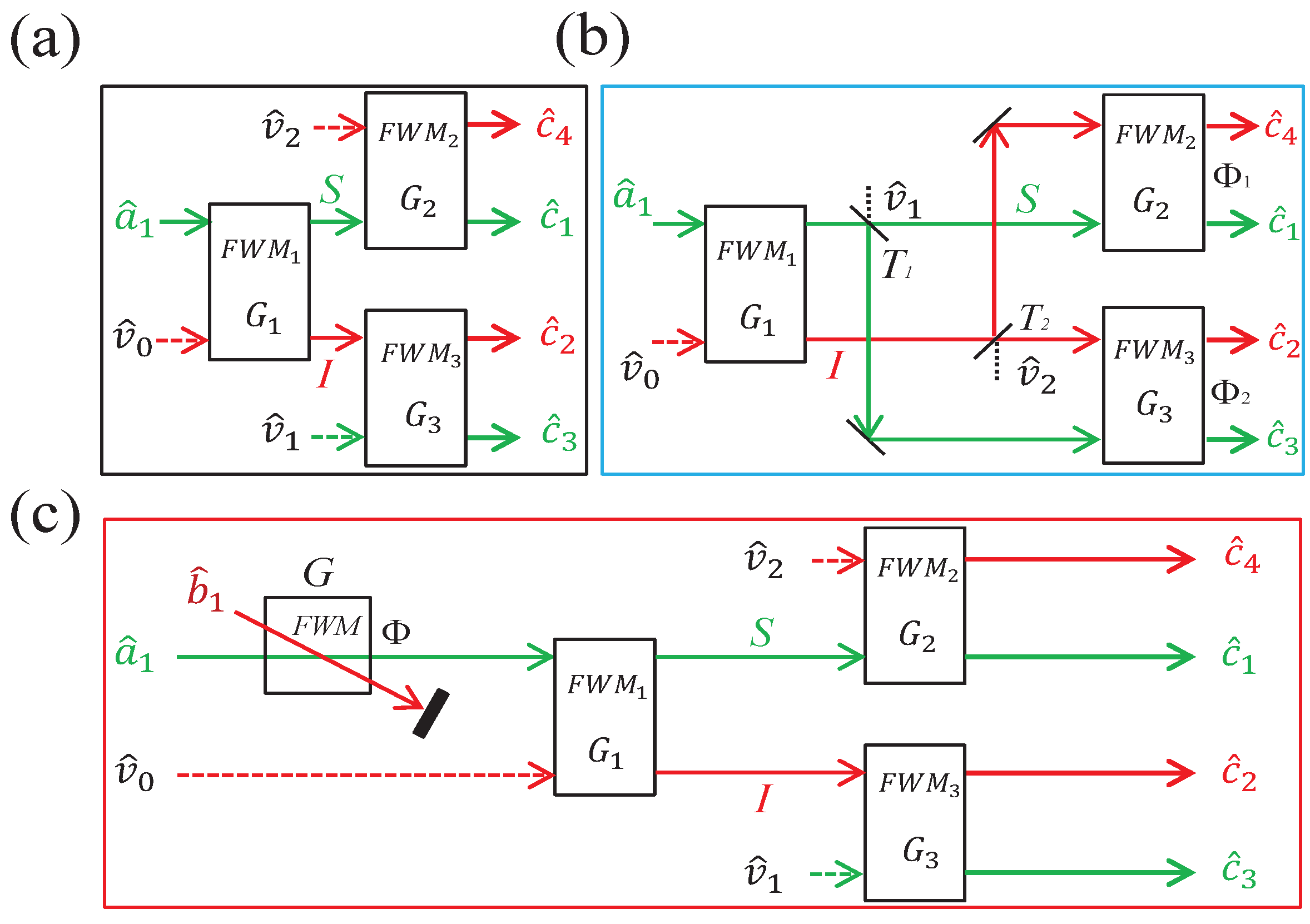
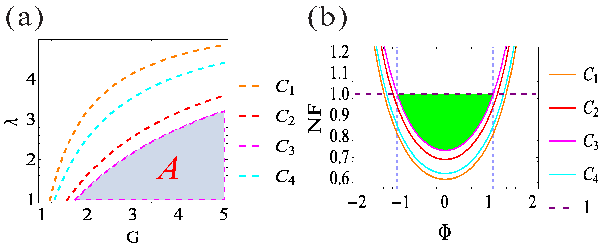
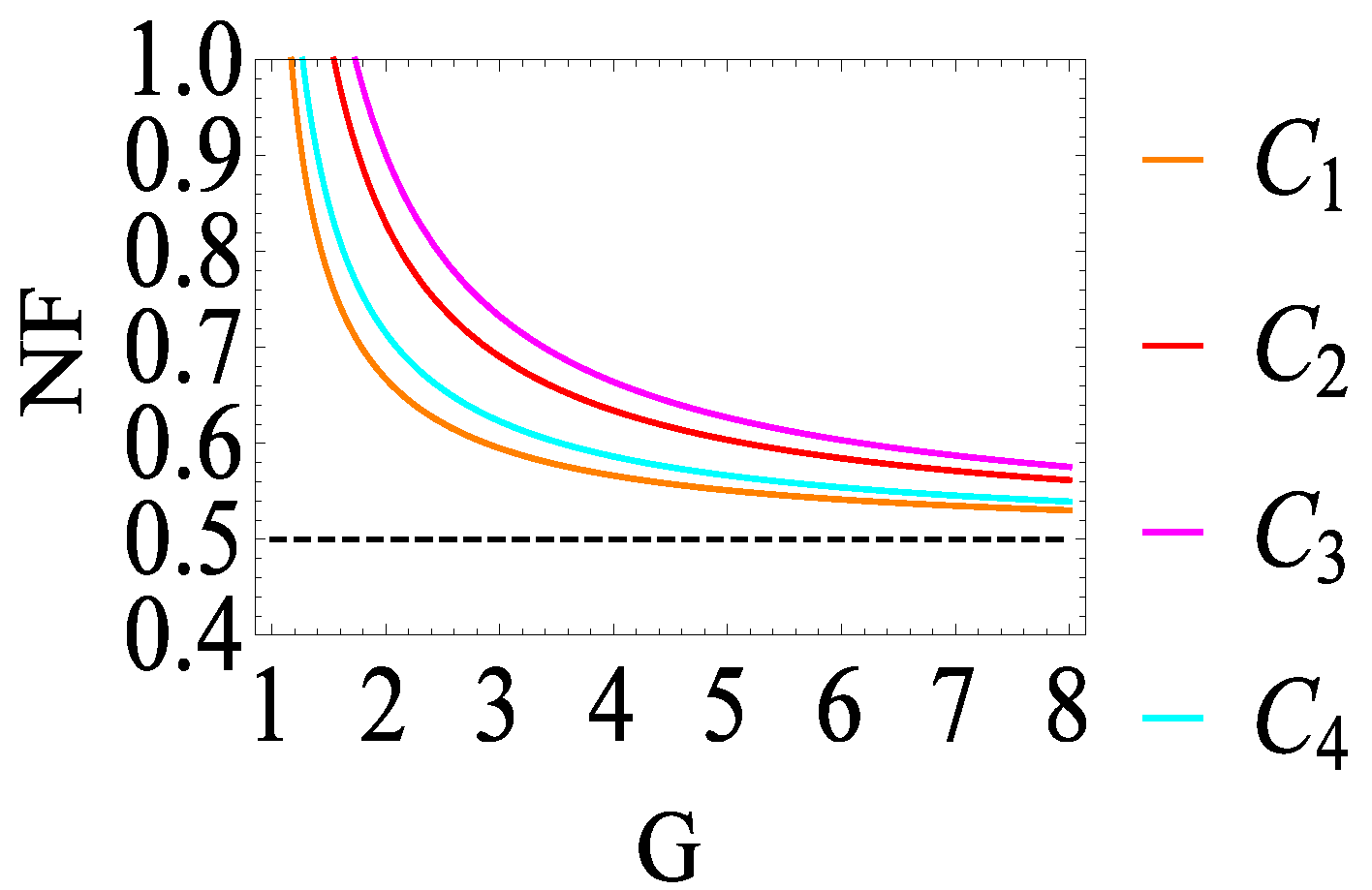
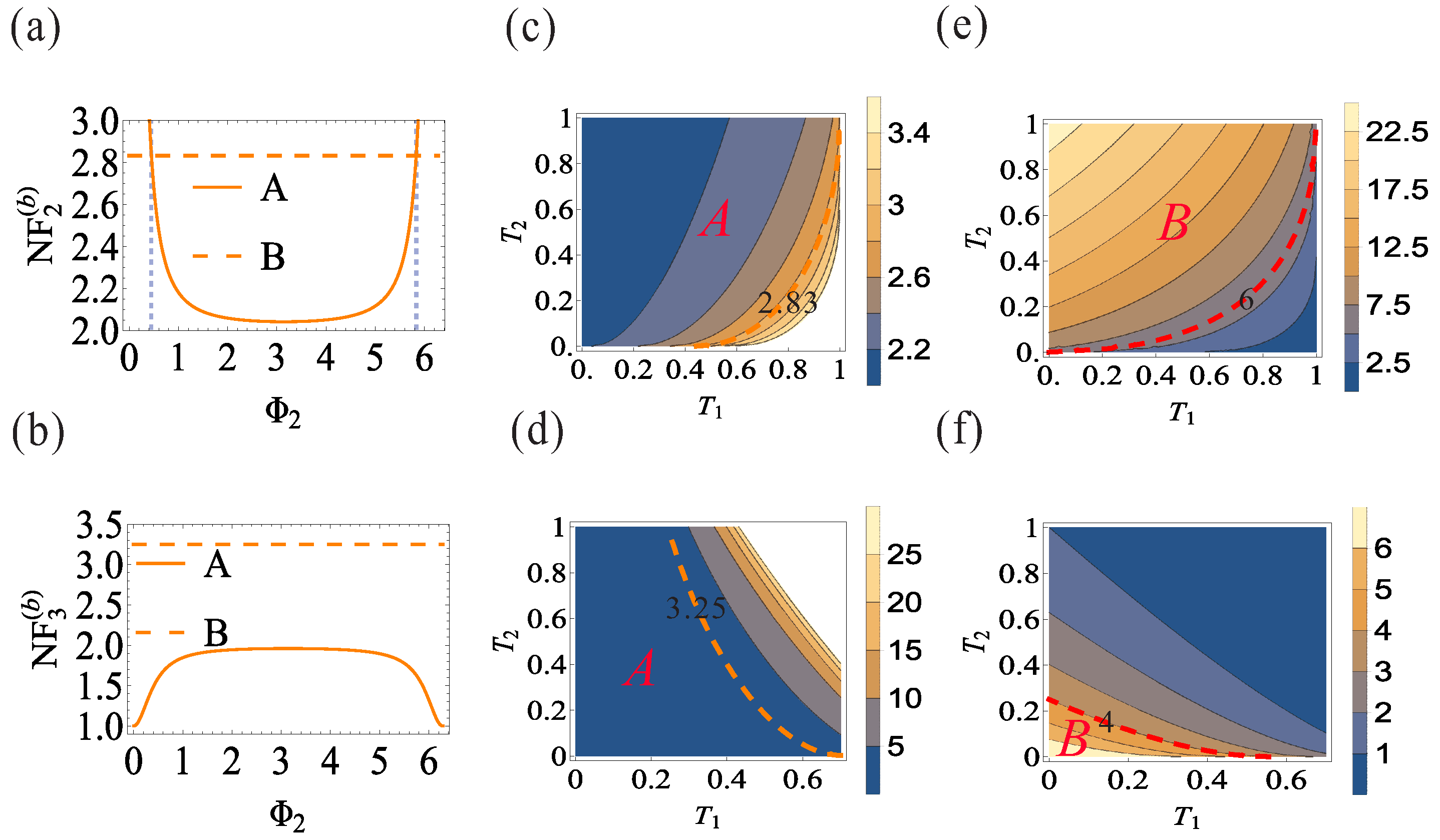
2. Symmetrical Cascaded FWM Process with Correlation Injection Scheme

As discussed above, compared with the impossibility of noiseless signal amplification in the symmetrical cascaded FWM process as shown in Figure 1a, the possibility of the realization of four-way noiseless signal amplification based on the correlation injection scheme will be discussed. As shown in Figure 1b, the signal and idler beams generated from the FWM 1 process with the reflective ratios of R 1 and R 2 are seeded into the dark ports in the FWM 3 and FWM 2 processes, respectively [21]. To be more specific, the signal (idler) beam with the reflective ratio of R 1 ( R 2 ) and the idler (signal) beam with the transmission ratio of T 2 ( T 1 ) are both seeded into the FWM 3 (FWM 2 ) process, and the FWM 2 and FWM 3 processes will become the phase-sensitive amplifiers due to the double seed configuration [22,23,24,25,26,27]. To obtain the NF values and gain values of this scheme, the input–output relation of the symmetrical cascaded FWM process with correlation injection scheme in Figure 1b can be given by
C ^ 1 ( b ) = C 11 a ^ 1 + C 12 ν ^ 0 + C 13 ν ^ 1 + C 14 ν ^ 2 , C ^ 4 ( b ) = C 41 a ^ 1 + C 42 ν ^ 0 + C 43 ν ^ 1 + C 44 ν ^ 2 , C ^ 2 ( b ) = C 21 a ^ 1 + C 22 ν ^ 0 + C 23 ν ^ 1 + C 24 ν ^ 2 , C ^ 3 ( b ) = C 31 a ^ 1 + C 32 ν ^ 0 + C 33 ν ^ 1 + C 34 ν ^ 2 ,
with
C 11 = G 1 G 2 T 1 g 1 g 2 R 2 e i Φ 1 , C 12 = G 2 g 1 T 1 G 1 g 2 R 2 e i Φ 1 , C 13 = G 2 R 1 , C 14 = g 2 T 2 e i Φ 1 , C 41 = G 1 g 2 T 1 e i Φ 1 G 2 g 1 R 2 , C 42 = g 1 g 2 T 1 e i Φ 1 G 1 G 2 R 2 , C 43 = g 2 R 1 e i Φ 1 , C 44 = G 2 T 2 , C 21 = G 2 g 1 T 2 G 1 g 2 R 1 e i Φ 2 , C 22 = G 1 G 2 T 2 g 1 g 2 R 1 e i Φ 2 , C 23 = g 2 T 1 e i Φ 2 , C 24 = G 2 R 2 , C 31 = g 1 g 2 T 2 e i Φ 2 G 1 G 2 R 1 , C 32 = G 1 g 2 T 2 e i Φ 2 G 2 g 1 R 1 , C 33 = G 2 T 1 , C 34 = g 2 R 2 e i Φ 2 ,
where Φ 1 and Φ 2 are the phases of the phase-sensitive FWM 2 and FWM 3 processes, respectively. Based on Equations (4) and (5), the NF values and gain values of the four output beams C ^ 1 , C ^ 4 , C ^ 2 , and C ^ 3 can be calculated analytically and expressed as
N F 1 ( b ) = ( 2 G 1 1 ) ( G 2 T 1 + g 2 R 2 ) + G 2 R 1 + g 2 T 2 4 α G 1 G 2 T 1 + g 1 g 2 R 2 2 α , N F 4 ( b ) = ( 2 G 1 1 ) ( G 2 R 2 + g 2 T 1 ) + G 2 T 2 + g 2 R 1 4 α G 1 g 2 T 1 + G 2 g 1 R 2 2 α , N F 2 ( b ) = ( 2 G 1 1 ) ( G 2 T 2 + g 2 R 1 ) + G 2 R 2 + g 2 T 1 4 β G 2 g 1 T 2 + G 1 g 2 R 1 2 β , N F 3 ( b ) = ( 2 G 1 1 ) ( G 2 R 1 + g 2 T 2 ) + G 2 T 1 + g 2 R 2 4 β G 1 G 2 R 1 + g 1 g 2 T 2 2 β ,
and
G 1 ( b ) = G 1 G 2 T 1 + g 1 g 2 R 2 2 α , G 4 ( b ) = G 1 g 2 T 1 + G 2 g 1 R 2 2 α , G 2 ( b ) = G 2 g 1 T 2 + G 1 g 2 R 1 2 β , G 3 ( b ) = g 1 g 2 T 2 + G 1 G 2 R 1 2 β ,
respectively, where α = G 1 G 2 g 1 g 2 T 1 R 2 cos Φ 1 and β = G 1 G 2 g 1 g 2 T 2 R 1 cos Φ 2 . Equation (6) will be reduced to Equation (3) when we set T 1 = T 2 = 1 and Φ 1 = Φ 2 = 0 , corresponding to the case of the symmetrical cascaded FWM process without the correlation injection scheme in Figure 1a. As can be calculated from Equation (6), the minimum value of N F 1 ( b ) (1) ( N F 4 ( b ) (2.04)) can be obtained for the case of T 1 = 1 , T 2 = 0 , and Φ 1 = 0 ( Φ 1 = π ). This means that the signal and idler beams generated from the FWM 1 process are totally seeded into the FWM 2 process. As shown in Figure 2, the dependence of N F 1 ( b ) and N F 4 ( b ) on Φ 1 for the case of T 1 = 1 and T 2 = 0 is shown in Figure 2a,b, respectively; the regions ( 0 < Φ 1 < 1.23 and 5.05< Φ 1 < 2 π ) and ( 1.05< Φ 1 < 5.24 ) smaller than 1.89 (trace B in Figure 2a) and 2.17 (trace B in Figure 2b), respectively, are the regions in which the values of N F 1 ( b ) and N F 4 ( b ) can be optimized compared with the corresponding ones, respectively, in Figure 1a. Here, the optimal phase point Φ 1 = π instead of Φ 1 = 0 for N F 4 ( b ) is because the denominator of N F 4 ( b ) is equal to 0 for the case of Φ 1 = 0 ; in this sense the value of N F 4 ( b ) will tend to infinity.
Next the dependence of the NF values and gain values of the two beams C ^ 1 and C ^ 4 on T 1 and T 2 with the optimal phase points will be discussed. Under the condition of Φ 1 = 0 , the region A in Figure 2c (right side of orange dashed line) is the region in which the NF value reduction and the gain value deamplification for the beam C ^ 1 can be realized simultaneously because the gain values G 1 ( b ) in Figure 2e are all smaller than G 1 G 2 = 9 . By contrast, the NF value reduction and the gain value amplification for the beam C ^ 4 can be realized simultaneously in the region A in Figure 2d (right side of orange dashed line) because the region B in Figure 2f (right side of red dashed line) contains the region A in Figure 2d. In this sense, the correlation injection scheme can only reduce the value of N F 1 ( b ) to 1 without amplifying its signal, because the value of G 1 ( b ) is equal to 1 under the condition of T 1 = 1 , T 2 = 0 , and Φ 1 = 0 . From the physical point of view, the above condition means that the configuration in Figure 1b is reduced to an SU(1,1) interferometer [22,23,24], and the special case of Φ 1 = 0 also implies that the SU(1,1) interferometer is operated on its dark fringe caused by destructive interference, in which quantum noise is canceled.
Similarly, for the two beams C ^ 2 and C ^ 3 , the minimum value of N F 2 ( b ) (2.04) ( N F 3 ( b ) (1)) can be obtained for the case of T 1 = 0 , T 2 = 1 , and Φ 2 = π ( Φ 2 = 0 ), meaning that the signal and idler beams generated from the FWM 1 process are totally seeded into the FWM 3 process. As shown in Figure 3a,c,e, the NF value N F 2 ( b ) reduction and the gain value G 2 ( b ) amplification for the beam C ^ 2 can be realized simultaneously in the region B in Figure 3e (left side of red dashed line) because the region A in Figure 3c (left side of orange dashed line) contains the region B in Figure 3e for the case of Φ 2 = π , while the NF value N F 3 ( b ) reduction and the gain value G 3 ( b ) amplification for the beam C ^ 3 can be realized simultaneously in the region B in Figure 3f (left side of red dashed line) because the region A in Figure 3d (left side of orange dashed line) contains the region B in Figure 3f for the case of Φ 2 = 0 . However, the correlation injection scheme can also reduce the value of N F 3 ( b ) to the noiseless level without amplifying its signal, because the value of G 3 ( b ) is equal to 1 under the condition of T 1 = 0 , T 2 = 1 , and Φ 2 = 0 . To sum up, the correlation injection scheme can only realize one-way noiseless signal amplification for the two beams C ^ 1 or C ^ 3 without an amplification effect, because the conditions for realizing noiseless signal amplification (( T 1 = 1 , T 2 = 0 , and Φ 1 = 0 ) and ( T 1 = 0 , T 2 = 1 , and Φ 2 = 0 ), respectively), are incompatible. Meanwhile, the NF values of the remaining two beams C ^ 2 and C ^ 4 are still bounded by the 3 dB penalty.

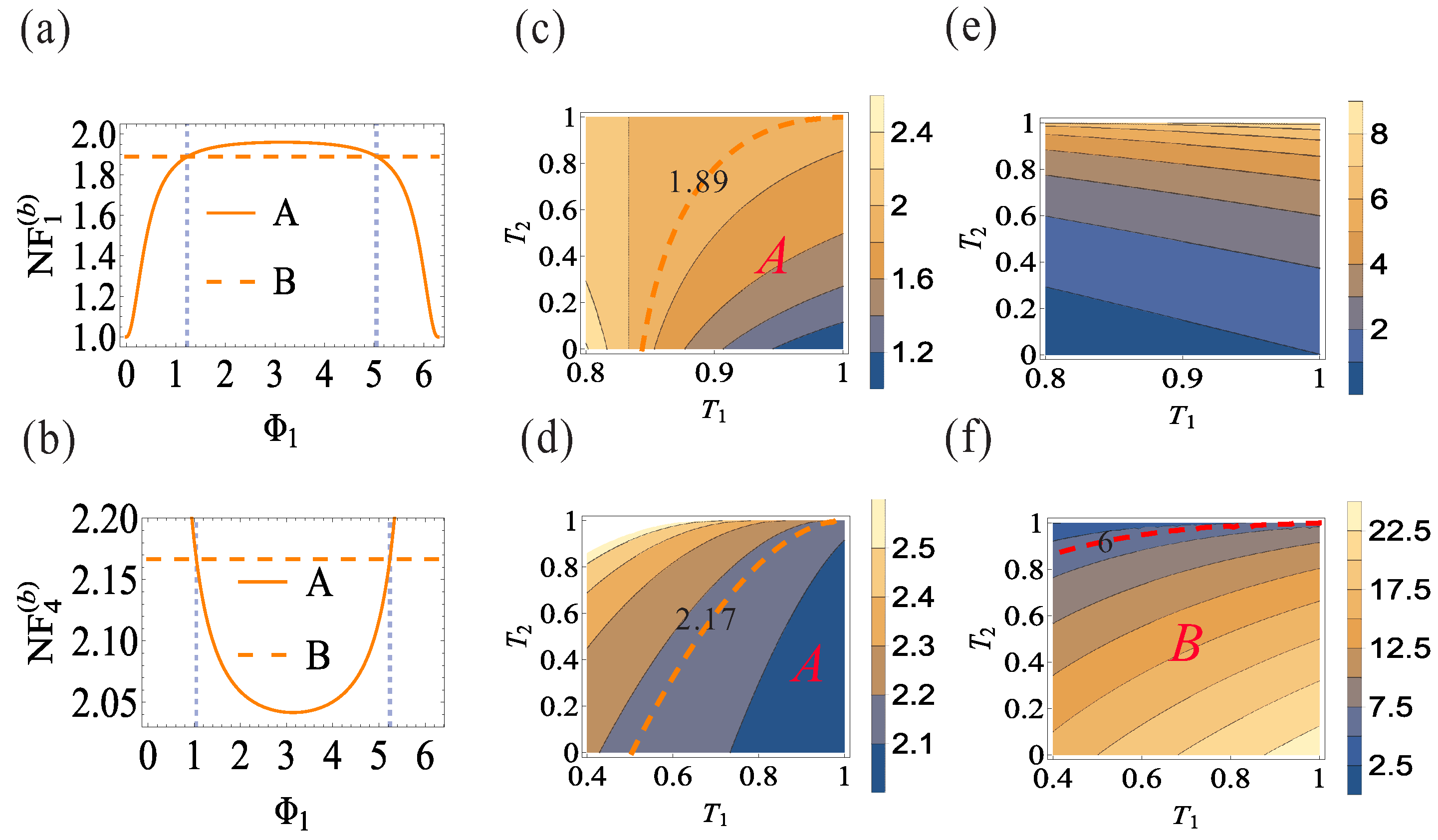
3. Symmetrical Cascaded FWM Process with Two-Beam Phase-Sensitive Amplifier Scheme

Because only one-way noiseless signal amplification can be realized by using the correlation injection scheme as shown in Figure 1b, the possibility of the realization of four-way noiseless signal amplification based on the two-beam phase-sensitive amplifier scheme in Figure 1c will be investigated in this section. As shown in Figure 1c, the coherent input signal beam a ^ 1 and the other coherent input idler beam b ^ 1 are simultaneously and symmetrically crossed in the center of the atomic vapor cell with power gain G, and this interaction mechanism can be described as the form of G a ^ 1 + g b ^ 1 e i Φ ( Φ is the phase in this process). This process can be understood as two individual phase-insensitive FWM processes seeded only by the signal or idler beam interfering with each other, while it is totally different from the single phase-insensitive FWM process [26,27]. Each FWM process produces its own output beams, respectively, then the two output beams with the same frequency overlap spatially, thus the two output beams are phase-sensitive. Following similar procedures, the input–output relations can be expressed as
C ^ 1 ( c ) = G G 1 G 2 a ^ 1 + g G 1 G 2 e i Φ b ^ 1 + G 2 g 1 v ^ 0 + + g 2 v ^ 2 , C ^ 4 ( c ) = G G 1 g 2 a ^ 1 + g G 1 g 2 e i Φ b ^ 1 + g 1 g 2 v ^ 0 + G 2 v ^ 2 , C ^ 2 ( c ) = G G 2 g 1 a ^ 1 + g G 2 g 1 e i Φ b ^ 1 + G 1 G 2 v ^ 0 + g 2 v ^ 1 , C ^ 3 ( c ) = G g 1 g 2 a ^ 1 + g g 1 g 2 e i Φ b ^ 1 + G 1 g 2 v ^ 0 + G 2 v ^ 1 ,
Based on the above expressions, the NF values and gain values for the two-beam phase-sensitive amplifier scheme can be expressed by
N F 1 ( c ) = Ω [ 2 G 1 G 1 G 2 ] , N F 4 ( c ) = Ω [ 2 G + 1 G 1 g 2 ] , N F 2 ( c ) = Ω [ 2 G + 2 G 2 1 G 2 g 1 ] , N F 3 ( c ) = Ω [ 2 G + 2 G 2 1 g 1 g 2 ] ,
and
G 1 ( c ) = G 1 G 2 Ω , G 4 ( c ) = G 1 g 2 Ω , G 2 ( c ) = G 2 g 1 Ω , G 3 ( c ) = g 1 g 2 Ω ,
respectively. Where Ω = λ G λ + g + 2 G g λ cos Φ and λ is the intensity ratio between the two beams a ^ 1 and b ^ 1 . Equation (9) will also be reduced to Equation (3) when we set G = 1 , corresponding to the case of the symmetrical cascaded FWM process without the two-beam phase-sensitive amplifier scheme in Figure 1a. The value of Ω is smaller than 1 if and only if G > 1 and Φ = 0 ; in this sense, the NF value reduction and the gain value amplification for all the four output beams in this scheme compared with the corresponding ones in Figure 1a may be realized simultaneously. Furthermore, it can be seen from Equation (10) that the gain values are always larger than the corresponding ones in the symmetrical cascaded FWM process without the two-beam phase-sensitive amplifier scheme, thus only the dependence of NF values on G, λ , and Φ will be discussed. As shown in Figure 4a, the regions on the bottom side of the orange dashed ( C 1 ), cyan dashed ( C 4 ), red dashed ( C 2 ), and magenta dashed ( C 3 ) lines in Figure 4a are the regions in which the values of N F 1 ( c ) , N F 4 ( c ) , N F 2 ( c ) , and N F 3 ( c ) , respectively, are all smaller than 1, meaning that this scheme can preferentially amplify the signal over the noise for all the four output beams, and four-way noiseless signal amplification can be realized in the smallest overlapping region A in Figure 4a. The physical mechanism of the realization of noiseless signal amplification from the two-beam phase-sensitive amplifier scheme can be explained as follows. Due to the introduction of the two-beam phase-sensitive amplifier as the pre-amplifier compared with the case in Figure 1a, its operating mechanism will be discussed firstly for the simplicity of explanation. According to the above NF definition N F = N i n 2 ( Δ N i n ) 2 / N o u t 2 ( Δ N o u t ) 2 = N i n ( Δ N i n ) 2 ( Δ N o u t ) 2 N o u t N i n N o u t , where the first and second terms are the reciprocal of the noise level of the input signal and the noise level of the output signal, respectively. Moreover, the noise level is defined as the ratio between the noise power and the standard quantum limit; thus the noise level of the input coherent signal is 1, and the noise level of the output amplified signal is 2 G 1 . In this sense, the noise level of the coherent input signal a ^ 1 is amplified by a factor of 2 G 1 after experiencing the amplification process, which is obviously independent of intensity ratio λ and phase Φ . The third term, on the other hand, i.e., the signal amplification factor G 1 ( c ) = 1 / Ω ( G 1 = G 2 = 1 ) from Equation (10), is obviously dependent on the intensity ratio λ and phase Φ ; thus the correct choice of these working parameters can guarantee its signal amplification over the noise amplification and thus an NF value less than 1. Then, this amplified signal is seeded into the sequential FWM processes to generate the four-way output signals, and their noiseless signal amplification performance will inevitably be slightly modified, as shown in Equation (9).
Similarly, this interesting phenomenon of an NF value less than 1 can also be seen in [9], in which the effect of loss on the NF value of both a phase-insensitive amplifier and a phase-sensitive amplifier is investigated. Here the loss is modeled by a beam splitter in the path of the beam before the detection but after the amplification process. The analytical results show that the NF value of phase-sensitive amplifier is always below 1 because the SNR of a shot-noise-limited input is degraded more with loss than the SNR of the amplified output, while the NF value of the phase-insensitive amplifier is below 1 only for the smaller loss value. Besides the theoretical analysis, the related experimental results can also be seen in this study. Another example is shown in [22], when the internal mode was correlated with the input mode and thus the amplifier was in an entangled state, the input SNR value was 5.4 dB, while the output SNR value was 6.6 dB. This also meant that the SNR of the amplified output was larger than the input SNR by 1.2 dB, i.e., the NF value was smaller than 1.
In addition, when the values of G and λ are set to 3 and 1, respectively (the results are shown in Figure 4b), the minimum values for N F 1 ( c ) (orange solid line C 1 ), N F 4 ( c ) (cyan solid line C 4 ), N F 2 ( c ) (red solid line C 2 ), and N F 3 ( c ) (magenta solid line C 3 ) are 0.59, 0.62, 0.69, and 0.73, respectively. The green overlapping region in between the blue dashed lines 1.1< Φ < 1.1 is a region where four-way NF values below 1 can be realized in the phase region.
Next, a natural question about the minimum values of Equation (9) has to be answered. Firstly, the minimum values of Equation (9) are all equal to 0 when we set λ = 0 , which is evidently impossible because λ = 0 requires the intensity of the beam b 1 to be infinite. Secondly, λ = 1 is always chosen due to the experimental operability [26,27]. In this sense the minimum values of Equation (9) are all equal to 0.5 in the high power gain limit, as shown in Figure 5; therefore, the ultimate minimum NF values obtained by the two-beam phase-sensitive amplifier scheme are all bounded by 0.5, while the intensities of all the four beams are also amplified by a factor of 4 G . Overall, the two-beam phase-sensitive amplifier scheme can lead to four-way NF values less than 1.

4. Conclusions

In conclusion, we theoretically analyzed the possibility of the realization of four-way noiseless signal amplification by using both a correlation injection scheme and a two-beam phase-sensitive amplifier scheme. The correlation injection scheme can only realize one-way noiseless signal amplification in some extreme cases, while the two-beam phase-sensitive amplifier scheme can lead to four-way NF values less than 1. Obviously, the two-beam phase-sensitive amplifier scheme we report here can also be readily extended to multiple-way noiseless signal amplification by cascading more FWM processes or by seeding an FWM process with a spatially structured pump [28,29,30,31,32,33]. These results also prove that the two-beam phase-sensitive amplifier is of great interest for several fields, including optical communications, such as the improvement in NF value [34], quantum information processing, e.g., the realization of quantum information tap [35,36,37] and the quantum non-demolition measurement [38,39,40,41,42], etc. In particular, if the two-beam phase-sensitive amplifier can support multiple spatial modes, it could perform the noiseless amplification of images and lead to an enhancement of optical resolution, which is an important goal in imaging research [9].

Author Contributions

All the authors contributed to the development of the conceptualization, discussed the results, and commented on the manuscript. Conceptualization, J.J.; Formal analysis, H.W.; Funding acquisition, H.W. and J.J.; Investigation, H.W. and C.Z.; Methodology, H.W. and S.J.; Resources, J.J.; Software, X.Z.; Supervision, J.J.; Validation, Y.Z., C.Z. and S.J.; Writing—original draft, H.W. All authors have read and agreed to the published version of the manuscript.

Funding

This research was funded by the Zhejiang Provincial Natural Science Foundation of China (LY22A040007), the National Natural Science Foundation of China (11804323, 11874155, 91436211, 11374104), the Fundamental Research Funds for the Provincial Universities of Zhejiang (2021YW29), the Innovation Program of Shanghai Municipal Education Commission (2021-01-07-00-08-E00100), the Basic Research Project of Shanghai Science and Technology Commission (20JC1416100), the Natural Science Foundation of Shanghai (17ZR1442900), the Minhang Leading Talents (201971), and the Shanghai Municipal Science and Technology Major Project (2019SHZDZX01), 111 project (B12024).

Institutional Review Board Statement

Not applicable.

Informed Consent Statement

Not applicable.

Data Availability Statement

Not applicable.

Conflicts of Interest

The authors declare no conflict of interest.

References

  1. Levenson, J.A.; Abram, I.; Rivera, T.; Fayolle, P.; Garreau, J.C.; Grangier, P. Quantum Optical Cloning Amplifier. Phys. Rev. Lett. 1993, 70, 267–270. [Google Scholar] [CrossRef] [PubMed]
  2. Haus, H.A.; Mullen, J.A. Quantum Noise in Linear Amplifiers. Phys. Rev. 1962, 128, 2407–2413. [Google Scholar] [CrossRef]
  3. Caves, C.M. Quantum limits on noise in linear amplifiers. Phys. Rev. D 1982, 26, 1817–1839. [Google Scholar] [CrossRef]
  4. Lam, P.K.; Ralph, T.C.; Huntington, E.H.; Bachor, H.A. Noiseless Signal Amplification using Positive Electro-Optic Feedforward. Phys. Rev. Lett. 1997, 79, 1471–1474. [Google Scholar] [CrossRef] [Green Version]
  5. Adnane, H.; Teklu, B.; Paris, M.G.A. Quantum phase communication channels assisted by non-deterministic noiseless amplifiers. J. Opt. Soc. Am. B 2019, 36, 2938–2945. [Google Scholar] [CrossRef]
  6. Trapani, J.; Teklu, B.; Olivares, S.; Paris, M.G.A. Quantum phase communication channels in the presence of static and dynamical phase diffusion. Phys. Rev. A 2015, 92, 012317. [Google Scholar] [CrossRef] [Green Version]
  7. Brivio, D.; Cialdi, S.; Vezzoli, S.; Gebrehiwot, B.T.; Genoni, M.G.; Olivares, S.; Paris, M.G.A. Experimental estimation of one-parameter qubit gates in the presence of phase diffusion. Phys. Rev. A 2010, 81, 012305. [Google Scholar] [CrossRef] [Green Version]
  8. Genoni, M.G.; Olivares, S.; Brivio, D.; Cialdi, S.; Cipriani, D.; Santamato, A.; Vezzoli, S.; Paris, M.G.A. Optical interferometry in the presence of large phase diffusion. Phys. Rev. A 2012, 85, 043817. [Google Scholar] [CrossRef] [Green Version]
  9. Corzo, N.V.; Marino, A.M.; Jones, K.M.; Lett, P.D. Noiseless Optical Amplifier Operating on Hundreds of Spatial Modes. Phys. Rev. Lett. 2012, 109, 043602. [Google Scholar] [CrossRef]
  10. Rosati, M.; Mari, A.; Giovannetti, V. Coherent-state discrimination via nonheralded probabilistic amplification. Phys. Rev. A 2016, 93, 062315. [Google Scholar] [CrossRef] [Green Version]
  11. McCormick, C.F.; Boyer, V.; Arimonda, E.; Lett, P.D. Strong relative intensity squeezing by four-wave mixing in rubidium vapor. Opt. Lett. 2007, 32, 178–180. [Google Scholar] [CrossRef] [PubMed] [Green Version]
  12. Boyer, V.; Marino, A.M.; Pooser, R.C.; Lett, P.D. Entangled Images from Four-Wave Mixing. Science 2008, 321, 544–547. [Google Scholar] [CrossRef] [PubMed] [Green Version]
  13. Liu, C.; Jing, J.; Zhou, Z.; Pooser, R.C.; Hudelist, F.; Zhou, L.; Zhang, W. Realization of low frequency and controllable bandwidth squeezing based on a four-wave-mixing amplifier in rubidium vapor. Opt. Lett. 2011, 36, 2979–2981. [Google Scholar] [CrossRef] [PubMed] [Green Version]
  14. Qin, Z.; Jing, J.; Zhou, J.; Liu, C.; Pooser, R.C.; Zhou, Z.; Zhang, W. Compact diode-laser-pumped quantum light source based on four-wave mixing in hot rubidium vapor. Opt. Lett. 2012, 37, 3141–3143. [Google Scholar] [CrossRef]
  15. Marino, A.M.; Pooser, R.C.; Boyer, V.; Lett, P.D. Tunable delay of Einstein–Podolsky-Rosen entanglement. Nature 2009, 457, 859–862. [Google Scholar] [CrossRef]
  16. Jasperse, M.; Turner, L.D.; Scholten, R.E. Relative intensity squeezing by four-wave mixing with loss: An analytic model and experimental diagnostic. Opt. Express 2011, 19, 3765–3774. [Google Scholar] [CrossRef] [Green Version]
  17. Guo, M.; Zhou, H.; Wang, D.; Gao, J.; Zhang, J.; Zhu, S. Experimental investigation of high-frequency-difference twin beams in hot cesium atoms. Phys. Rev. A 2014, 89, 033813. [Google Scholar] [CrossRef] [Green Version]
  18. Cao, L.; Qi, J.; Du, J.; Jing, J. Experimental generation of quadruple quantum-correlated beams from hot rubidium vapor by cascaded four-wave mixing using spatial multiplexing. Phys. Rev. A 2017, 95, 023803. [Google Scholar] [CrossRef]
  19. Cao, L.; Wang, W.; Lou, Y.; Du, J.; Jing, J. Experimental characterization of pairwise correlations from quadruple quantum correlated beams generated by cascaded four-wave mixing processes. Appl. Phys. Lett. 2018, 112, 251102. [Google Scholar] [CrossRef]
  20. Corzo, N.V. Multi-Spatial-Mode Phase Sensitive Optical Amplifier. Ph.D. Thesis, National Institute of Standards and Technology and University of Maryland, College Park, MD, USA, 2012. [Google Scholar]
  21. Wang, H.; Zhang, K.; Ni, Z.; Jing, J. Enhancement of quantum correlations using correlation injection scheme in a cascaded four-wave mixing processes. Opt. Express 2020, 28, 10633–10647. [Google Scholar] [CrossRef]
  22. Kong, J.; Hudelist, F.; Ou, Z.; Zhang, W. Cancellation of Internal Quantum Noise of an Amplifier by Quantum Correlation. Phys. Rev. Lett. 2013, 111, 033608. [Google Scholar] [CrossRef] [PubMed]
  23. Jing, J.; Liu, C.; Zhou, Z.; Ou, Z.; Zhang, W. Realization of a nonlinear interferometer with parametric amplifiers. Appl. Phys. Lett. 2011, 99, 011110. [Google Scholar] [CrossRef]
  24. Hudelist, F.; Kong, J.; Liu, C.; Jing, J.; Ou, Z.; Zhang, W. Quantum metrology with parametric amplifier based photon correlation interferometers. Nat. Commun. 2014, 5, 3049. [Google Scholar] [CrossRef] [PubMed] [Green Version]
  25. Fang, Y.; Jing, J. Quantum squeezing and entanglement from a two-mode phase-sensitive amplifier via four-wave mixing in rubidium vapor. New J. Phys. 2015, 17, 023027. [Google Scholar] [CrossRef] [Green Version]
  26. Fang, Y.; Feng, J.; Cao, L.; Wang, Y.; Jing, J. Experimental implementation of a nonlinear beamsplitter based on a phase-sensitive parametric amplifier. Appl. Phys. Lett. 2016, 108, 131106. [Google Scholar] [CrossRef]
  27. Liu, S.; Lou, Y.; Jing, J. Interference-Induced Quantum Squeezing Enhancement in a Two-beam Phase-Sensitive Amplifier. Phys. Rev. Lett. 2019, 123, 113602. [Google Scholar] [CrossRef]
  28. Knutson, E.M.; Cross, J.S.; Wyllie, S.; Glasser, R.T. Phase-sensitive amplification via multi-phase-matched four-wave mixing. Opt. Express 2020, 28, 22748–22754. [Google Scholar] [CrossRef]
  29. Wang, H.; Fabre, C.; Jing, J. Single-step fabrication of scalable multimode quantum resources using four-wave mixing with a spatially structured pump. Phys. Rev. A 2017, 95, 051802(R). [Google Scholar] [CrossRef]
  30. Knutson, E.M.; Swaim, J.D.; Wyllie, S.; Glasser, R.T. Optimal mode configuration for multiple phase-matched four-wave-mixing processes. Phys. Rev. A 2018, 98, 013828. [Google Scholar] [CrossRef] [Green Version]
  31. Swaim, J.D.; Knutson, E.M.; Danaci, O.; Glasser, R.T. Multimode four-wave mixing with a spatially structured pump. Opt. Lett. 2018, 43, 2716–2719. [Google Scholar] [CrossRef] [Green Version]
  32. Zhang, K.; Wang, W.; Liu, S.; Pan, X.; Du, J.; Lou, Y.; Yu, S.; Lv, S.; Treps, N.; Fabre, C.; et al. Reconfigurable Hexapartite Entanglement by Spatially Multiplexed Four-Wave Mixing Processes. Phys. Rev. Lett. 2020, 124, 090501. [Google Scholar] [CrossRef] [PubMed]
  33. Wang, H.; Zhang, K.; Treps, N.; Fabre, C.; Zhang, J.; Jing, J. Generation of hexapartite entanglement in a four-wave-mixing process with a spatially structured pump: Theoretical study. Phys. Rev. A 2020, 102, 022417. [Google Scholar] [CrossRef]
  34. Tong, Z.; Lundström, C.; Andrekson, P.A.; McKinstrie, C.J.; Karlsson, M.; Blessing, D.J.; Tipsuwannakul, E.; Puttnam, B.J.; Toda, H.; Nielsen, L.G. Towards ultrasensitive optical links enabled by low-noise phase-sensitive amplifiers. Nat. Photonics 2011, 5, 430–436. [Google Scholar] [CrossRef]
  35. Bruckmeier, R.; Hansen, H.; Schiller, S.; Mlynek, J. Realization of a Paradigm for Quantum Measurements: The Squeezed Light Beam Splitter. Phys. Rev. Lett. 1997, 79, 43–46. [Google Scholar] [CrossRef] [Green Version]
  36. Poizat, J.P.; Grangier, P. Experimental Realization of a Quantum Optical Tap. Phys. Rev. Lett. 1993, 70, 271–274. [Google Scholar] [CrossRef] [Green Version]
  37. Pereira, S.F.; Ou, Z.; Kimble, H.J. Backaction Evading Measurements for Quantum Nondemolition Detection and Quantum Optical Tapping. Phys. Rev. Lett. 1994, 72, 214–217. [Google Scholar] [CrossRef] [Green Version]
  38. Bencheikh, K.; Levenson, J.A.; Grangier, P.; Lopez, O. Quantum Nondemolition Demonstration via Repeated Backaction Evading Measurements. Phys. Rev. Lett. 1995, 75, 3422–3425. [Google Scholar] [CrossRef]
  39. Roch, J.F.; Vigneron, K.; Grelu, P.; Sinatra, A.; Poizat, J.P.; Grangier, P. Quantum Nondemolition Measurements Using Cold Trapped Atoms. Phys. Rev. Lett. 1997, 78, 634–637. [Google Scholar] [CrossRef]
  40. Bruckmeier, R.; Schneider, K.; Schiller, S.; Mlynek, J. Quantum Nondemolition Measurements Improved by a Squeezed Meter Input. Phys. Rev. Lett. 1997, 78, 1243–1246. [Google Scholar] [CrossRef]
  41. Bruckmeier, R.; Hansen, H.; Schiller, S. Repeated Quantum Nondemolition Measurements of Continuous Optical Waves. Phys. Rev. Lett. 1997, 79, 1463–1466. [Google Scholar] [CrossRef]
  42. Holland, M.J.; Collett, M.J.; Walls, D.F.; Levenson, M.D. Nonideal quantum nondemolition measurements. Phys. Rev. A 1990, 42, 2995–3005. [Google Scholar] [CrossRef] [PubMed]
Figure 1. The schemes for the generation of four-way noiseless signal amplification from a symmetrical cascaded FWM process (a), with a correlation injection scheme (b), and with a two-beam phase-sensitive amplifier scheme (c). a ^ 1 and b ^ 1 are the coherent input signal beam and the coherent input idler beam, respectively. ν ^ 0 , ν ^ 1 , and ν ^ 2 are the vacuum inputs, and c ^ 1 , c ^ 2 , c ^ 3 , and c ^ 4 are the four output beams, respectively. S and I represent the signal and idler beams, respectively. G i (i = 1–3) is the power gain in the individual FWM i process, and Φ 1 , Φ 2 , and Φ are the phases of the FWM 2 process, FWM 3 process, and pre-amplifier in (c), respectively. T 1 and T 2 are the transmission ratios for signal and idler beams, respectively, generated from the FWM 1 process.
Photonics 09 00229 g001
Figure 2. The dependence of N F 1 ( b ) and N F 4 ( b ) in Equation (6) on Φ 1 under the condition of T 1 = 1 and T 2 = 0 (traces A in (a,b)), and T 1 and T 2 under the condition of Φ 1 = 0 ( Φ 1 = π ) in (c,d). The dependence of G 1 ( b ) and G 4 ( b ) in Equation (7) on T 1 and T 2 under the condition of Φ 1 = 0 ( Φ 1 = π ) in (e,f). The orange and red dashed lines in all the figures are the NF values and gain values, respectively, from the symmetrical FWM processes without the correlation injection scheme in Figure 1a. The vertical blue dashed lines in (a,b) are Φ 1 = ( 1.23 , 5.05) and Φ 1 = ( 1.05 , 5.24), respectively. All the above figures are obtained for the case of G 1 = G 2 = 3 .
Photonics 09 00229 g002
Figure 3. The dependence of N F 2 ( b ) and N F 3 ( b ) in Equation (6) on Φ 2 under the condition of T 1 = 0 and T 2 = 1 (traces A in (a,b)), and T 1 and T 2 under the condition of Φ 2 = π ( Φ 2 = 0 ) in (c,d). The dependence of G 2 ( b ) and G 3 ( b ) in Equation (7) on T 1 and T 2 under the condition of Φ 2 = π ( Φ 2 = 0 ) in (e,f). The vertical blue dashed lines in (a) are Φ 2 = ( 1.05 , 5.24). See Figure 2 for others.
Photonics 09 00229 g003
Figure 4. The dependence of Equation (9) on G and λ for the case of Φ = 0 in (a), and Φ for the case of G = 3 and λ = 1 in (b). The purple dashed line is 1, and the vertical dashed lines are Φ = ( 1.1, 1.1) .
Photonics 09 00229 g004
Figure 5. The dependence of Equation (9) on G for the case of λ = 1 and Φ = 0 . The black dashed line is 0.5.
Photonics 09 00229 g005
Publisher’s Note: MDPI stays neutral with regard to jurisdictional claims in published maps and institutional affiliations.

