Article

Real-Time Phase Retrieval Based on Cube-Corner Prisms Single Exposure

Key Laboratory of Intelligent Computing & Signal Processing, Anhui University, Ministry of Education, Hefei 230601, China
*
Author to whom correspondence should be addressed.
Photonics 2022, 9(4), 230; https://doi.org/10.3390/photonics9040230
Submission received: 9 March 2022 / Revised: 25 March 2022 / Accepted: 30 March 2022 / Published: 1 April 2022
(This article belongs to the Special Issue Optical 3D Sensing Systems)

Abstract

:
The phase retrieval method based on the Transport of Intensity Equation needs to record the light intensity information on two or more planes perpendicular to the optical axis propagating along the optical axis. Usually, a single CCD camera is moved back and forth for recording, which not only brings the corresponding mechanical errors, but also has a certain time difference between the collected intensity images, which cannot meet the real-time requirements. In this paper, a single phase retrieval technique based on cube-corner prisms is proposed. This method can simultaneously collect the required initial intensity image in a single exposure, and then calculate the phase after registration and repair, so as to obtain high-precision results. According to the parallel reflection characteristics of the cube-corner prisms, the experimental system designed correspondingly can not only stagger the two beams separated by the beam splitter, but also ensure that the upper and lower propagation distances of a single beam are equal. Finally, the accuracy and effectiveness of the proposed method are fully verified by simulation experiments and experimental measurements.

1. Introduction

Phase is one of the important information in the field of optical measurement, which includes the depth, shape, refractive index, etc., of the surface of the object, but general optical imaging instruments cannot directly obtain phase information. In order to obtain the phase information of the light field, many methods have been proposed [1,2,3,4,5]. The phase retrieval algorithm based on the Transport of Intensity Equation (TIE) [6] can calculate the phase information from the intensity information of the object, which is proven to be an effective phase retrieval algorithm. This method is non-interfering and non-iterative, and does not require phase unwrapping [7,8]. It has been applied in many fields such as electron microscopy [9], X-ray diffraction imaging [10], three-dimensional reconstruction [11], and so on. The solution of the transport of intensity equation needs to record the light intensity information on two or more planes perpendicular to the optical axis propagating along the optical axis [12]. Usually, a single CCD camera moves back and forth for acquisition, which not only reduces the speed of acquisition, but the mechanical movement itself will also bring corresponding errors.
In order to solve the above problems, in 2010, Laura Waller et al. used volume holographic microscope to realize single phase imaging [13,14]. In 2013, Zuo et al. utilized a phase spatial light modulator to modulate the defocus distance [15]. In 2018, H. Kwon et al. realized the retrieval of complex field values by using random electrolyte super-surface diffuser device with known characteristics [16], and in 2020 proposed a quantitative phase gradient microscope, which can obtain three intensity images for phase calculation at the same time [17]. In 2019, A.K. Gupta et al. proposed a scheme based on refractive index change [18], and Zhang et al. used dual cameras to realize dynamic phase imaging [19]. In 2021, E. Engay proposed to use a single polarization-dependent all-dielectric element surface to promote the simultaneous recording of two images [20]. These methods have been proven to be effective TIE phase imaging techniques, but their equipment is complex and difficult to implement.
In 2018, Li et al. proposed a flip imaging scheme [21] which can easily obtain two defocused intensity images, but this method has high requirements on the collimation of the optical path, and if half-wave loss is considered there may be an additional phase difference of π between the two reflected lights in this method. In 2020, A.K. Gupta et al. applied a traditional Michelson interferometer-like structure for single-shot phase imaging based on the intensity equation [22]. In this paper, the mirror is tilted slightly so that, in a single shot, two laterally separated defocused images are obtained, and a single-shot TIE with a simpler configuration is realized. This method does not cause the problem of phase difference. However, due to the inclination of the mirror, the optical paths traveled by different parts of the optical path are not equal, resulting in a certain error in the intensity image after imaging.
In this paper, a single-shot phase retrieval technology based on cube-corner prisms is proposed. According to the parallel reflection characteristics of cube-corner prisms, it not only staggers the two beams split by the beam splitter laterally, but also ensures the up and down propagation distance of a single beam of light. It is not necessary to make the cube-corner prism plane strictly perpendicular to the optical path, and preprocessing operations such as registration and restoration are performed on the captured images. Through this technology, the intensity images at different defocus distances can be collected under a single exposure. After registration and repair, the phase can be solved by using the transport of intensity equation. In this paper, the corresponding simulation experiments and experimental measurements are designed, and the experimental results show that the method can effectively obtain the phase results.

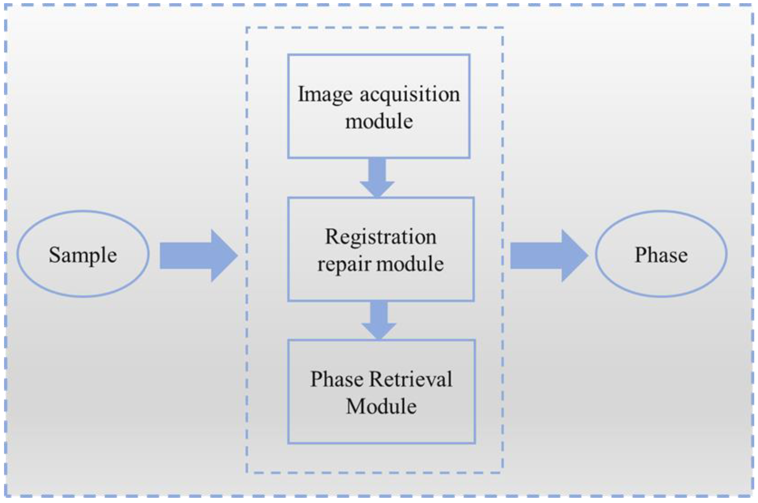
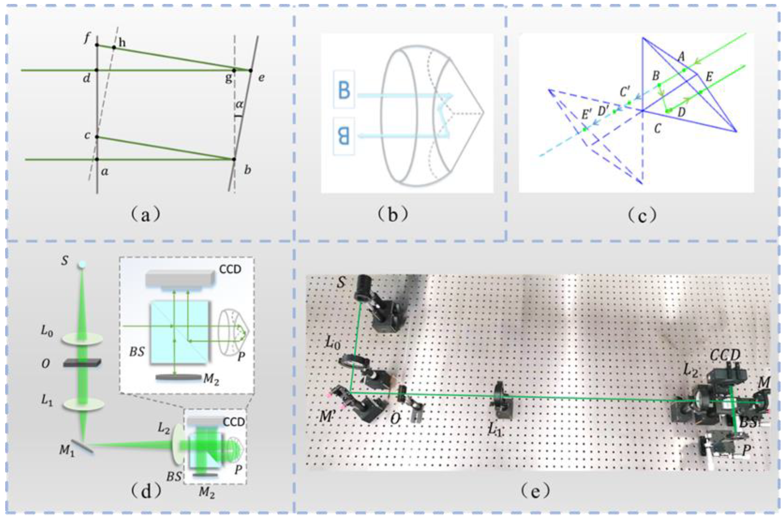
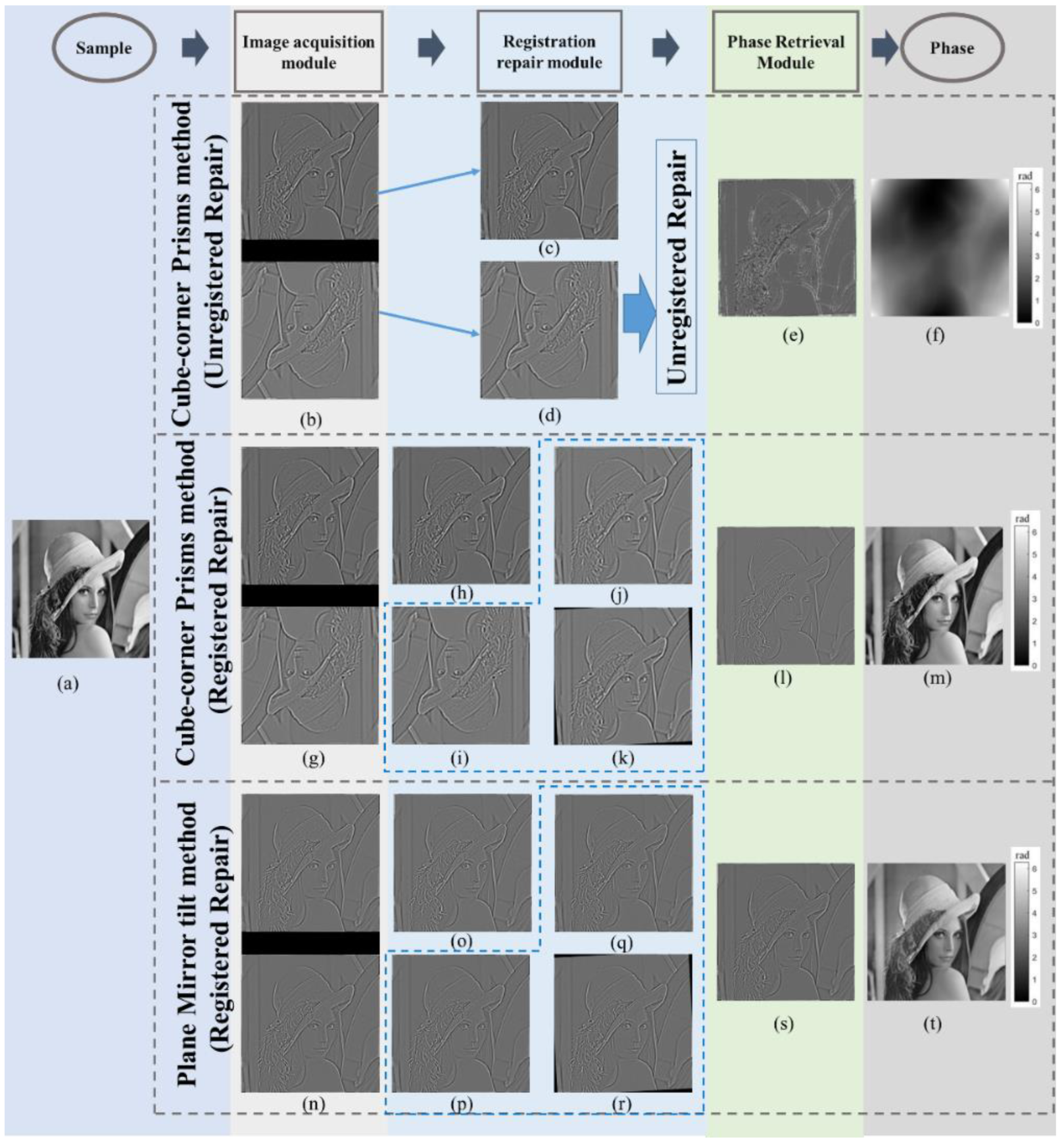
2. Phase Retrieval Imaging Technology Based on Cube-Corner Prisms

The phase retrieval imaging technology based on cube-corner mainly includes three modules, the image acquisition module, registration repair module, and phase retrieval module. The specific flow is shown in Figure 1. The sample first obtains a combined intensity image through the image acquisition module. After segmentation, it enters the registration and repair module to obtain two intensity images with different defocus distances at the same spatial position, and finally enters the phase retrieval module and solves for phase.

2.1. Image Acquisition Module

As mentioned in the introduction, the mirror tilt method in reference [22] has to tilt the mirror slightly to obtain two laterally separated defocused images in a single shot. Assume that the parallel lights ab and de are irradiated on a mirror with an inclination angle of α, and then reflected to points c and f, respectively. As can be seen from Figure 2a, the distance traveled by de is longer than that traveled by the line segments ge and fh, which is the distance traveled when reflected with a flat mirror, and is not equal. In order to avoid the above problems, this paper puts forward the scheme of cube-corner prisms.
A cube-corner prism [23], also known as retroreflector, has three mutually perpendicular reflective surfaces; as shown in Figure 2b, no matter what the incident angle is, the reflected light is always parallel to the incident light, and the reflection angle is also always kept at 180 degrees. The reflection image is inverted and reversed. Based on its properties, cube-corner prisms are often used in long-distance measurement, optical signal analysis, and imaging of laser devices.
The principle of the light path of the cube-corner prism is shown in Figure 2c. Assuming that the light path is incident in the AB direction and exits after passing through the ABCDE point, according to the mirror image rule, the total path traveled is equal to the length of the line segment AE′, that is, the incident direction line is slanted by two mirror images. The length of the intercepted line segment is such that when the incident direction remains unchanged, the optical path traveled is a fixed value and will not change.
The optical path of the image acquisition module based on the cube-corner prism designed in this paper is shown in Figure 2d: it is composed of a point-shaped green light source (S), a collimating lens (L0), a test sample (O), two lenses with focal lengths f1 and f2 (L1 and L2, respectively), beam splitter (BS), mirrors (M1 and M2), cube-corner prism (P), and CCD camera (CCD). M2, P, and CCD are found in the dotted line box in the upper right corner, an enlarged view of the constructed cube-corner imaging module.
The light emitted by the point light source is adjusted into parallel light through the collimating lens for illumination. The lenses L1 and L2 form a 4f imaging system to ensure the equivalence of the object plane and the image plane. After the light path enters the pyramid imaging module, it will be divided into two paths; one is reflected by the beam splitter to M2, and finally imaged on the left side of the CCD, and the other involves the cube-corner prism. Due to the reflection characteristics of the cube-corner prism, the formed image can undergo a certain amount of lateral displacement, and is finally imaged on the CCD on the right. After adjusting the two paths to focus, we moved the corner prism P forward by a set distance, and moved the mirror M2 backward by the same distance, so that two defocus intensity images can be collected in one exposure. In this acquisition module, the optical paths experienced by each part of the image are equal, which avoids the errors introduced by the unequal optical paths in reference [22].
In order to verify the effectiveness of the method in this paper, we conducted experimental measurements and built the following optical path system, as shown in Figure 2e. The experimental apparatus in the figure is the same as that in Figure 2d.
The green light of LED (model: GCI-060403) with a central wavelength of λ ¯ = 532   nm was used as the light source in the experiment. The point light source emitted by the LED is adjusted into parallel light through the space diaphragm and collimating lens ( f = 30   cm ), and then enters the 4f imaging system with the addition of the cube-corner prism (model: GCI-030502) imaging module. The focal lengths of the system lenses L1 and L2 are both 30 cm.
Firstly, the image formed by two light paths is adjusted to the focusing position; taking the focus position as a reference, two defocus images with defocus distance of 3mm are obtained by adjusting the plane mirror and cube-corner prism. The intensity distribution on the plane orthogonal to the optical axis under the same illumination state is collected by CCD, and then substituted into the registration repair module and the phase retrieval module to obtain the final retrieval result. In order to verify the effectiveness of the proposed method in real experiments, we use lithography samples and micro-lens array samples for qualitative and quantitative experiments in Section 3.2.

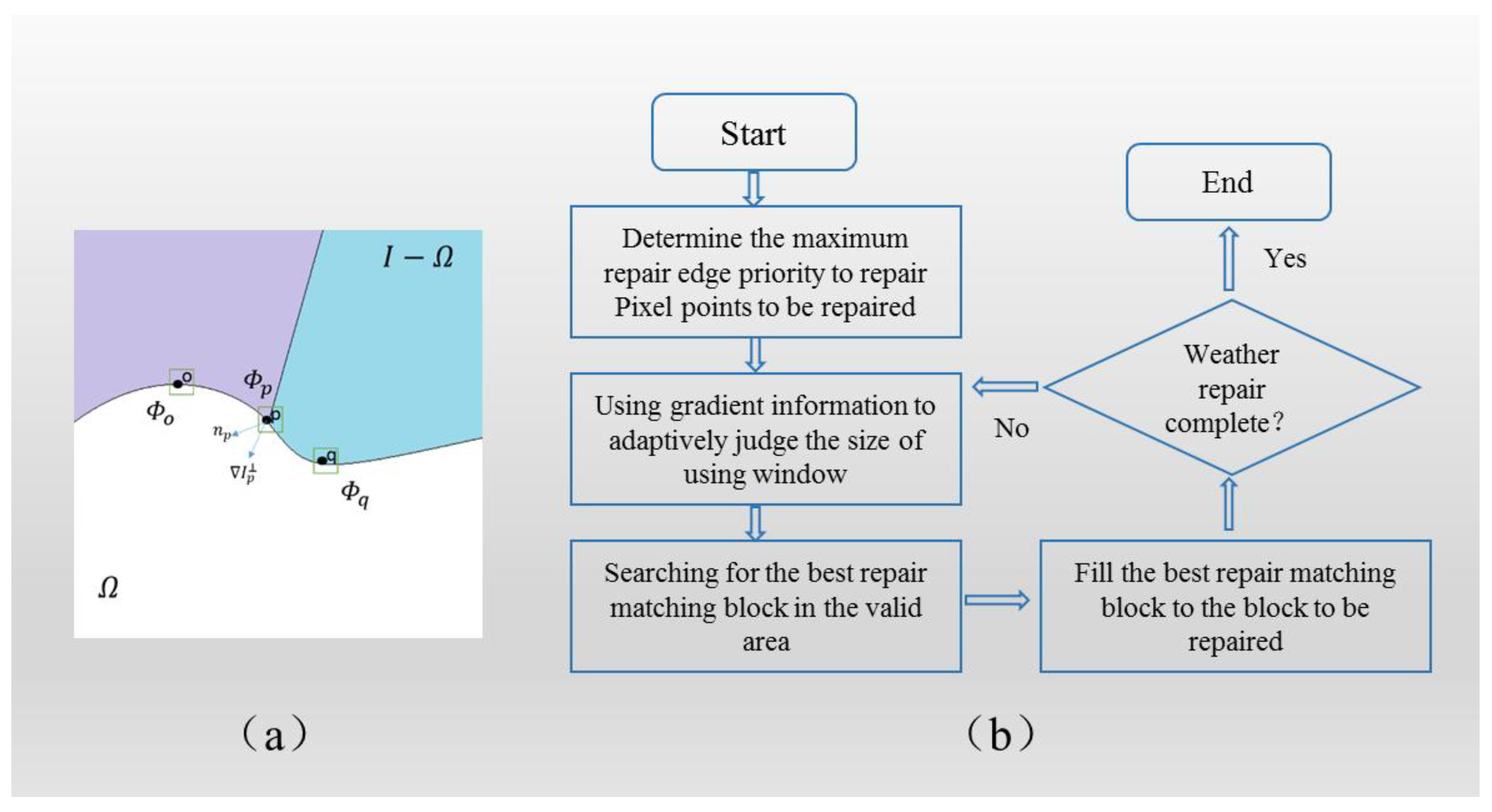
2.2. Registration Repair Module

2.2.1. Harris Corner Registration Algorithm

After obtaining two defocused images in one exposure image by using the above optical path structure, it is necessary to divide them into two defocused images. However, in practical experiments, it is impossible to guarantee that the two defocused images are evenly distributed in the collected image in equal proportion, so it is necessary to register the two images with a registration repair module after segmentation [24].
Assume that the collected over-focus image is I ( x , y , z 0 + Δ z ) , and the under-focus image is I ( x , y , z 0 Δ z ) . Taking the under-focused image as the reference image, firstly detect and extract Harris feature points from I ( x , y , z 0 + Δ z ) and I ( x , y , z 0 Δ z ) .
The principle is to take a window (usually a rectangular area) centered on the target pixel point and move it in any direction with a slight displacement, and record the amount of grayscale change in the window; we think that a corner point is encountered in the window and select it as a feature point. The gray scale change can be expressed as:
E ( x , y ) = w x , y ( H x + u , y + v H x , y ) 2 = w x , y [ u H X + v H X + o ( u 2 + v 2 ) ] 2
where u and v represent the offset of the window centered on ( x , y ) in the X and Y direction, respectively, E ( x , y ) is the grayscale change in the window, w x , y is the window function, H is the image grayscale function, and o ( u 2 + v 2 ) is the infinitesimal term. The position information of the feature points is determined by the degree of grayscale change in each direction within the window.
Then, the feature points between the two images are matched, and the normalized cross-correlation between the feature points on the two matched images is compared, and the calculated maximum correlation coefficient corresponds to the best match. Then, the RANSAC algorithm is used to purify the feature point pair, and the root mean square error of the corresponding feature point is used as the purification standard, as shown in the formula:
R M S E = i k f ( q i , T ) p i 2 ω
In the formula, q i and p i are a pair of matching point pairs, and ω is the number of matching point pairs. We consider the point where R M S E < c (threshold) is the matching point. When there are too many matching points between the two images, it is easy to be mismatched. The initial value of the threshold is preset to 0.85, and then the threshold is adjusted up or down according to the number of matching points in the matching result, and the number of matching points is adjusted between 3 and 5 pairs. Then, we solved the spatial transformation model T between images according to the matching points. The spatial transformation model T is as follows:
T = [ cos θ sin θ t x sin θ cos θ t y 0 0 1 ]
Finally, we geometrically transformed the over-focus image I ( x , y , z 0 + Δ z ) according to the transformation model T to obtain the transformed defocus intensity image, and the relationship is expressed by the following formula.
I r ( x , y , z 0 + Δ z ) = T [ I ( x , y , z 0 + Δ z ) ]

2.2.2. Fast Adaptive Repair Algorithm

Although two defocused images can be placed in the same spatial position by using registration algorithm, a hole error will be introduced at the same time. For the hole area in the image I r ( x , y , z 0 + Δ z ) after registration, the fast adaptive repair algorithm in the registration repair module is used to repair it. This algorithm is improved based on the Criminisi algorithm [25]. The principle of the Criminisi algorithm is shown in Figure 3a.
Denote the area to be repaired as Ω , the part of I Ω , p represents the pixel with the highest priority on the boundary, Φ o represents the pixel area with Φ o as the center p . The information of this area is partly known, and part of the information to be filled is unknown. I p represents the direction of the iso-illuminance line of p . n p represents the p normal vector. The flow of the Criminisi algorithm is shown in Figure 3b.
First, we determined the pixel with the highest priority on the boundary of the area to be repaired in the image, and estimate Φ p . The priority P ( p ) of the pixel on the boundary is calculated as follows:
P ( p ) = C ( p ) × D ( p )
Among them, C ( p ) is the confidence item, which represents the proportion of the known information already contained in the pixel area of the target block S × S , and D ( p ) is the data item to ensure that the target block with more structural information is repaired first. The combination of C ( p ) and D ( p ) can promote structure retention and texture matching to reach a balance point.
C ( p ) = p Φ p I Ω c ( p ) | Φ p | ;   D ( p ) = | I p × n p | β
where | Φ p | is the area of Φ p , where β is the normalization factor, and n p is the normal vector of p , which is used to measure the proportion of the known information of the target block Φ p .
In the process of calculating the priority of the above algorithm, as the fill progresses, the confidence value will decrease rapidly, which makes the calculation of priority unreliable, leads to the wrong filling order, and then affects the repair result. In order to overcome this shortcoming, we give a more reasonable priority update function to ensure the correct filling of image structure and texture, and define priority as the weighted sum of these two items:
P ( p ) = C ( p ) + α D ( p )
Among them, α is the set weight value, so that the data item occupies a more important position in determining the priority, and the specific value is determined with the sample.
After finding the point p with the highest priority among the pixels on the boundary, we used the gradient information to adaptively judge the size of the window to be used, and then searched for the repair block with the highest priority. Let Φ p ^ represent the block to be repaired with the highest priority. Φ q is the area for matching. The optimal sample block Φ q ^ is determined as follows:
Φ q ^ = arg min d ( Φ q ^ , Φ q ) Φ q ^ Ω
Among them, d ( Φ q ^ , Φ q ) represents the distance between Φ q ^ and Φ q , and the calculation formula is as follows:
d ( Φ q ^ , Φ q ) = i j | Φ q ^ ( i , j ) Φ q ( i , j ) | 2
Then, we filled the repair block into the block to be repaired, and repeated the above process until the area to be repaired was completely repaired, and then stopped to finally obtain the repaired over-focus image I r ( x , y , z 0 + Δ z ) .

2.2.3. Phase Retrieval Module

The principle of phase recovery module in phase recovery imaging technology based on cube-corner prism is to solve the phase based on intensity transfer equation, and the formula is as follows:
k z I ( x , y , z 0 ) = ( I ( x , y , z 0 ) φ ( x , y , z 0 ) )
Among them, I ( x , y , z 0 ) is the light intensity at z = z 0 , φ ( x , y , z 0 ) is the phase at z = z 0 , z = / z is the change of the intensity distribution along the z-axis, k is the wave number, and the wavelength satisfies k = 2 π / λ , and = ( x , y ) is the gradient operator.
In the above formula, z I ( x , y , z 0 ) represents the variation of the intensity distribution along the z-axis, which cannot be measured directly, but can be approximated by image difference, that is,
z I ( x , y , z 0 ) I r ( x , y , z 0 + Δ z ) I ( x , y , z 0 Δ z ) 2 Δ z
Δ z represents the defocusing distance. The TIE-based phase retrieval method is suitable for small defocusing distances. When the defocusing distance is too large, nonlinear errors will be introduced, which have a great impact on the accuracy of the retrieval results [26].
I ( x , y , z 0 ) is the light intensity at z = z 0 , generally replaced by the mean value of over-focus and under-focus intensities:
I ( x , y , z 0 ) I r ( x , y , z 0 + Δ z ) + I ( x , y , z 0 Δ z ) 2
By substituting the intensity image into the TIE solved by the Fourier solution method [27], the phase information φ ( x , y , z 0 ) at can be solved at z = z 0 .
φ ( x , y , z 0 ) = 1 k 2 { · [ I 1 ( x , y , z 0 ) ψ ( x , y , z 0 ) ] } = 1 k - 2 { · [ I 1 ( x , y , z 0 ) [ 1 k 2 [ k z I ( x , y , z 0 ) ] ] ] }
Among them, represents the Fourier transform, and 1 represents the inverse Fourier transform.

3. Experiment

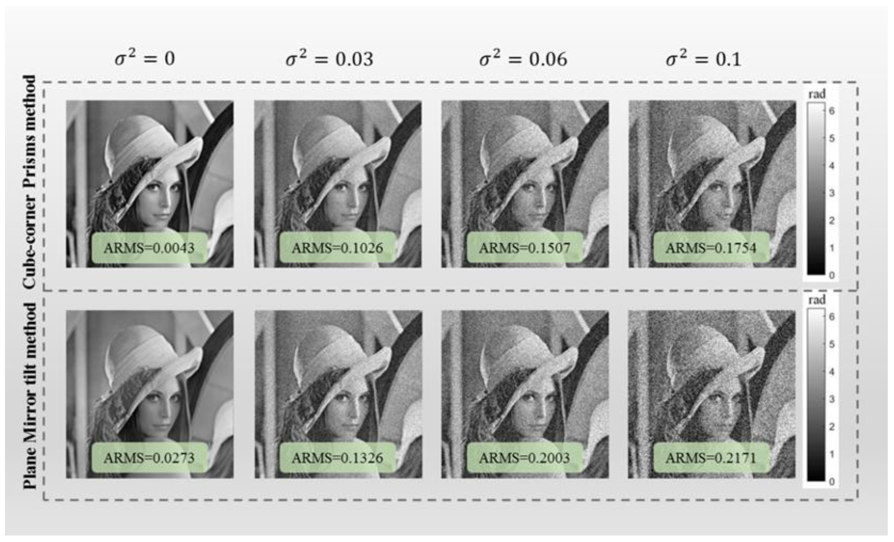
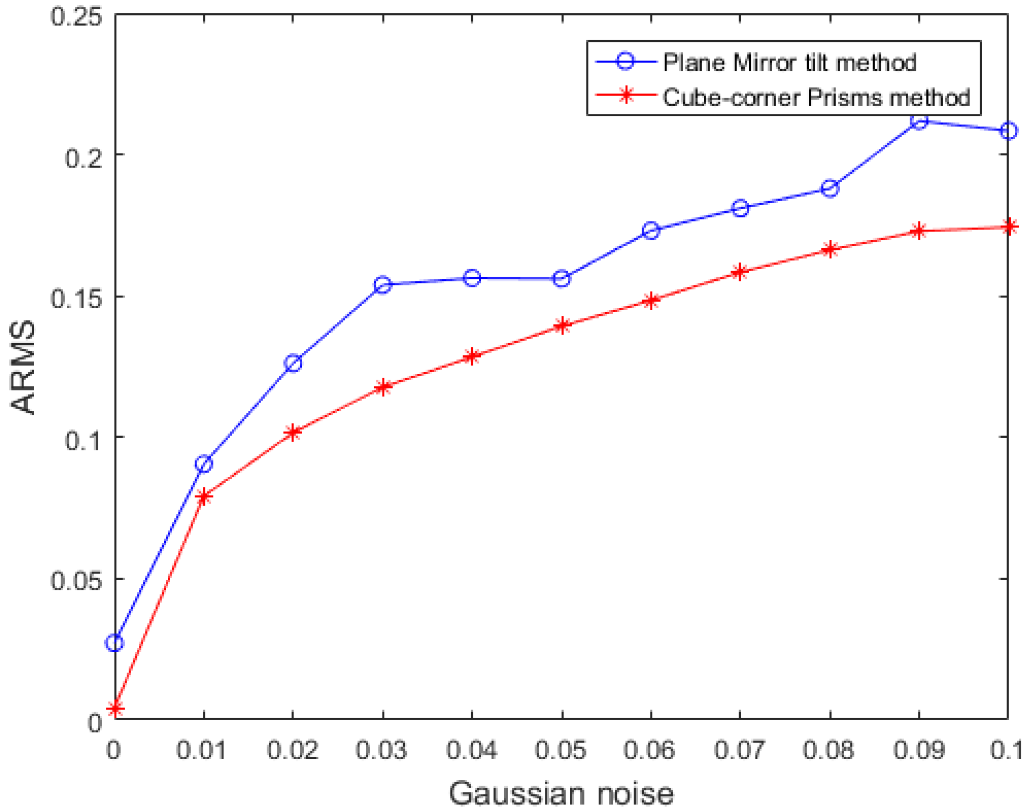
3.1. Simulation Experiment

In the first group of simulation experiments, a pure phase object with an intensity of 1 was selected as the sample, the phase range was 0 2 π , the pixel size was 256 pixel × 256 pixel, the wavelength was set to 532 nm, and the defocus distance was set to 50 μm.
Figure 4 shows the experimental process and results of the phase retrieval imaging of the cube-corner method (unregistered and registered repairs) and the plane mirror tilt method (registered repairs) were explored. The first row of gray dashed boxes is the experimental process of the unregistered repair of the cube-corner method, the second row of gray dashed boxes is the experimental process of the cube-corner prism method of registration repair, and the third row of gray dashed boxes is the experimental process of registration repair in the flat mirror tilt method in the literature [20] (assuming that the mirror is tilted 3°, that is, the difference between the propagation distance between the upper boundary and the lower boundary is set to be 5 μm).
Figure 4a is the selected sample. It first enters the image acquisition module, and simulates the intensity images obtained by the cube-corner method and the plane mirror tilt method that contain both under-focus and over-focus information, and then enters the registration repair module. The first dotted box in the row is the experimental process and results of the misregistered repair of the cube-corner method proposed in this paper. Different columns correspond to different modules. During the registration and repair module process, the cube-corner method in the first row is unregistered and repaired, while the blue dotted boxes in the second and third rows represent the registration and repair process. The over-focus intensity images shown in Figure 4i,p were registered and repaired based on the under-focus intensity images shown in Figure 4h,o, respectively. The images in the phase retrieval module show the intensity difference, and the last column is the retrieved phase.
It can be seen intuitively from the image that the restoration result of the cube-corner method after the registration repair is more similar to the input phase.
In order to quantitatively describe the accuracy of the above phase retrieval algorithm, the absolute mean square error (ARMS) between the retrieved phase φ 1 ( x , y , z ) and the original phase φ ( x , y , z ) is defined as follows:
A R M S = 1 M N   [ φ ( x , y , z ) φ 1 ( x , y , z , ) ] 2
Among them, M , N represent the size of the image. The absolute mean square error of the cube-corner method (unregistered repair) calculated using the above formula is 0.1325, the absolute mean square error of the cube-corner method (registered repair) is 0.0344, and the absolute mean square error of the plane mirror tilt method (registered repair) is 0.0273. The method in this paper improves the accuracy of restoration through registration repair, avoids the error of unequal propagation distances in the plane mirror tilt method, and has a small absolute mean square error.
The second set of simulation experiments tests the sensitivity of the method in this paper to noise. We add noise on the basis of the first set of simulation experiments. Figure 5 shows the retrieval results of the cube-corner method and the plane mirror tilt method under the condition of adding noise with different variances. At the same time, the experiment gives the absolute mean square error value under different noise conditions. The first line is the cube-corner method in this paper, and the second line is the plane mirror tilt method in the literature [22]. It can be seen from the figure that, under the same noise condition, the retrieval effect of the corner prism method is better.
Figure 6 is the absolute mean square error curve of the method in this paper and the plane mirror tilt method after adding Gaussian noise with a variance of 0 0.1 . The red line in the figure represents the error value of the cube-corner method, and the blue line represents the error value of the plane mirror tilt method. After adding noise, the algorithm proposed in this paper can still obtain good results, which proves that the method in this paper has good anti-noise performance.

3.2. Experimental Measurements

In order to verify the effectiveness of the method in this paper, we conducted experimental measurements, built the optical path system as shown in Figure 2e, and conducted qualitative and quantitative experiments using lithography samples and micro-lens array samples, respectively.

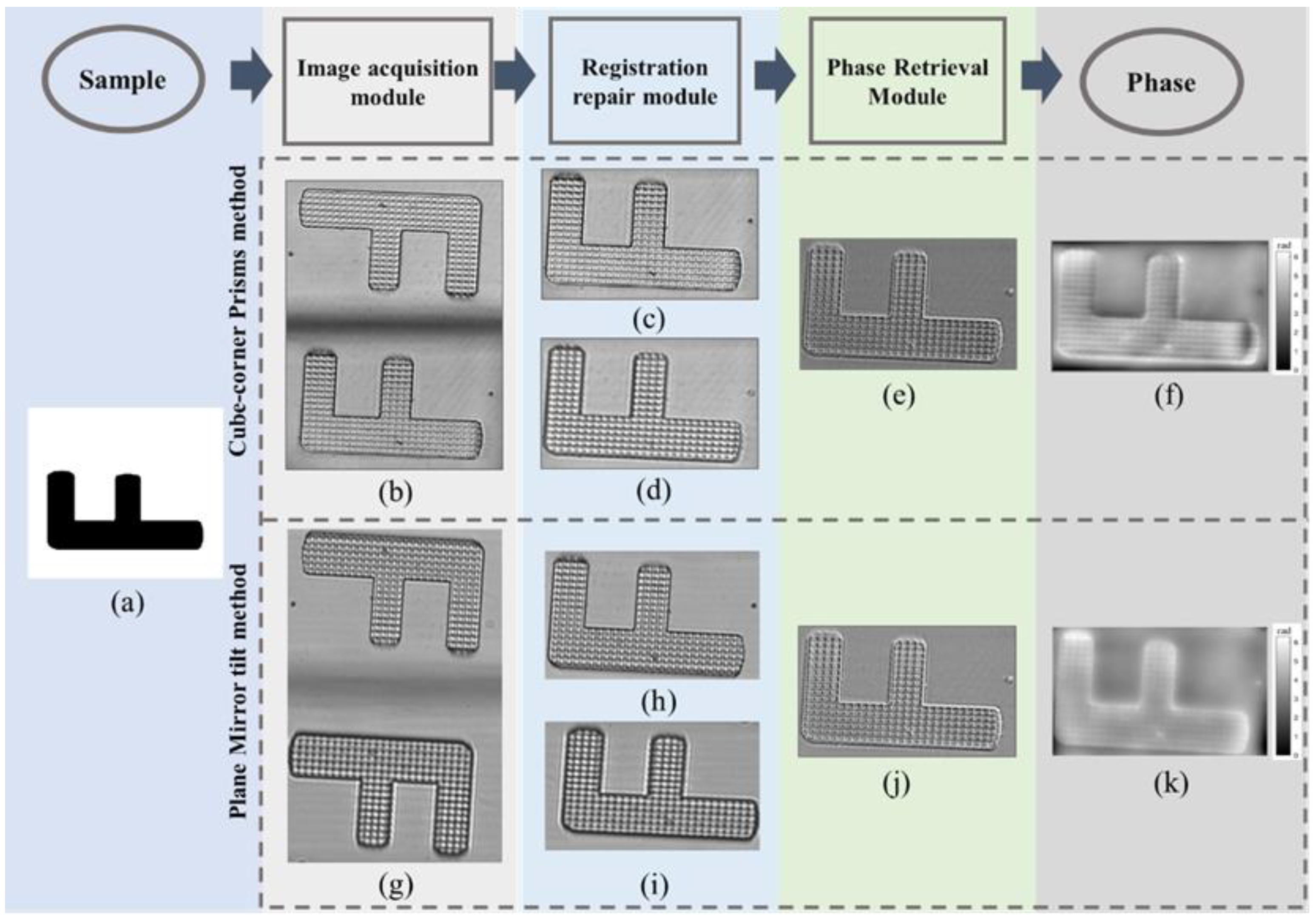
3.2.1. Qualitative Experiments Based on Lithography Samples

We use the computer generated hologram and direct writing system (model: HoloMakerlVB) to achieve the sample production. First, a sample pattern is generated by a computer, then the sample pattern is printed on a glass substrate attached with photoresist, and then it is immersed in a 10% NaOH solution for cleaning to obtain a photolithographic sample of a phase object as a test sample 1.
We placed the lithography sample in the imaging optical path shown in Figure 2e for the experiment, and Figure 7 shows the experimental process and results of the lithography sample. The dotted box above is the experimental process and results of the cube-corner method in this paper, Figure 7a is the lithography sample, Figure 7b is the intensity image obtained by shooting, Figure 7c is the original under-focus intensity image, Figure 7d is the restoration after the over-focus intensity image, Figure 7e is the intensity difference, and Figure 7f is the retrieved phase result.
The dotted box below is the experimental process and results of the plane mirror tilt method. When the plane mirror is tilted by 5°, the two intensity images can be staggered from each other. Figure 7a is the lithography sample, Figure 7g is the intensity image obtained by shooting, Figure 7h is the original under-focus intensity image, Figure 7i is the repaired over-focus intensity image, Figure 7j is the intensity difference, and Figure 7k is the restored phase result. The grayscale changes in the figure correspond to the depth.

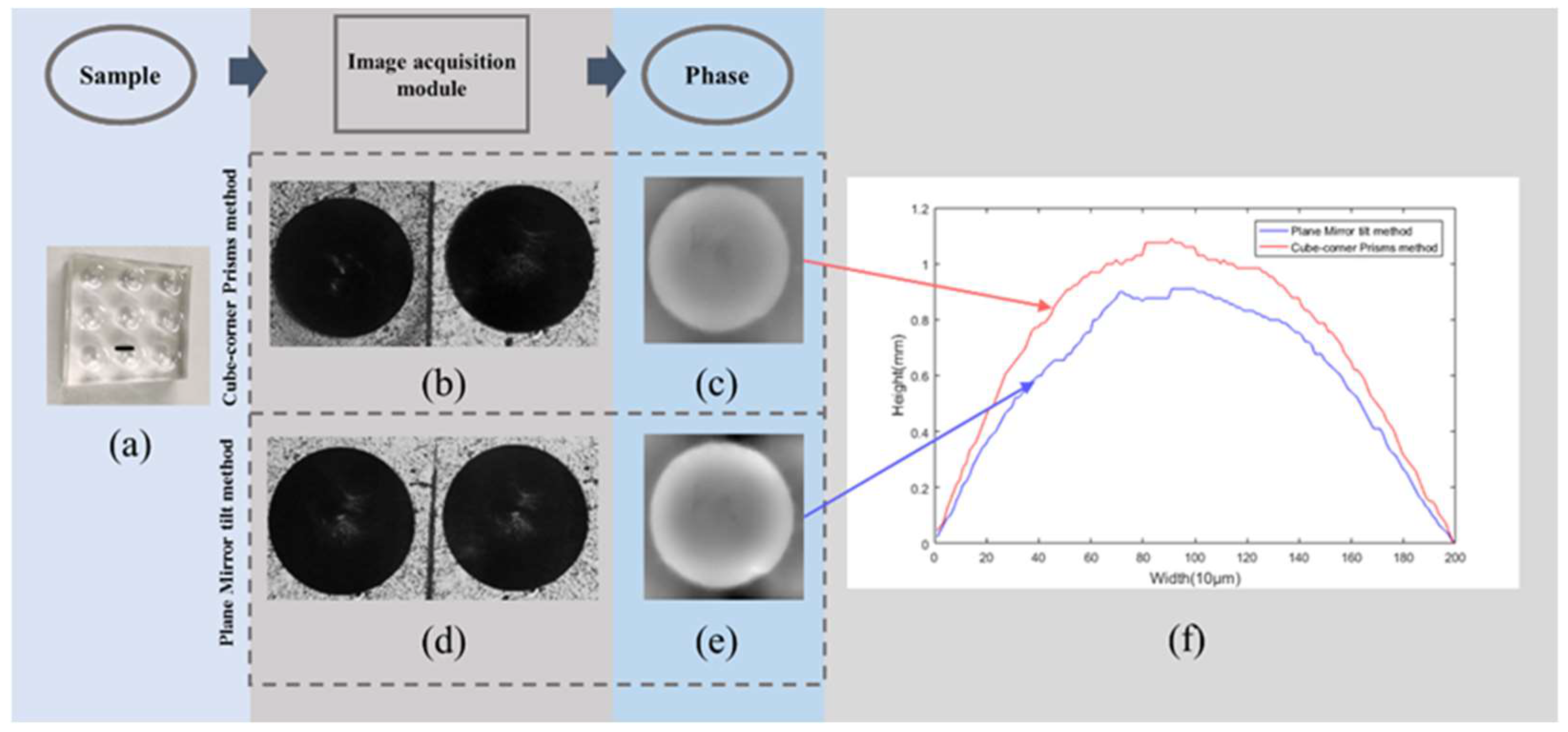
3.2.2. Quantitative Experiment Based on Micro-Lens Array

Test sample 2 is a micro-lens array with a size of 2 cm × 2 cm and a number of micro-lenses of 3 × 3. Each small lens in the lens array is made of silicone oil with a refractive index of 1.579. The filling material is polydimethylsiloxane with a refractive index of 1.403, and the maximum thickness of each micro-lens is about 1.15 mm [28]. The micro-lens sample is shown in Figure 8a.
The first row of Figure 8 is the retrieval process and result of the cube-corner method proposed in this paper. Among them, Figure 8b is the intensity image obtained by the cube-corner method, and Figure 8c is the retrieval result of the cube-corner method. The second behavior is the retrieval process and results of the plane mirror tilt method in [22]. When the plane mirror is tilted by 4°, the over-focus image and the under-focus image can just be staggered. Among them, Figure 8d is the intensity image obtained by the plane mirror tilting method, and Figure 8e is the restoration result of the plane mirror tilting method.
Reference [29] pointed out that there is a certain relationship between the thickness of the object to be measured and the obtained phase and refractive index:
L ( x , y , z ) = λ n 0 n m × φ ( x , y , z ) 2 π
Among them, n m is the refractive index of the medium around the test object, and n 0 is the refractive index of the test object. The specific depth value of the micro-lens array can be calculated according to the formula.
Taking the cross-section of the black horizontal line in Figure 8a as the standard, the comparison results of the depth value of the horizontal cross-section of the two methods are given. As shown in Figure 8f, the blue line is the retrieval result of the corner prism method, the yellow line is the restoration result of the plane mirror tilt method. After calculation, the maximum depth value of the cube-corner method is about 1.09 mm, and the relative error with the true depth is 5.2%; the maximum depth value of the plane mirror tilt method is about 0.91 mm, and the phase error with the true depth is 20.8%. From the experimental error value, it can be seen that the phase retrieved by the method in this paper is better.

4. Discussion

The traditional TIE-based phase retrieval method needs to move the object or CCD when collecting light intensity images, which will introduce certain mechanical errors, and cannot collect intensity images at the same time to ensure real-time requirements. In this paper, a single-shot phase retrieval method based on a cube-corner prism is proposed. Through the image acquisition module composed of a beam splitter, a cube corner prism and a plane mirror, two intensity images can be simultaneously acquired in one exposure. The high-precision phase is then solved by the registration repair and phase retrieval modules. Both simulation and experimental measurements results demonstrate the effectiveness and correctness of the method.

5. Conclusions

The phase retrieval module in this paper is proposed based on the transport of intensity equation method, using the classical Fourier solution method. However, this solution method relies on restrictive pre-knowledge or assumptions, including appropriate boundary conditions, well-defined closed regions, etc. The lack of these pre-knowledge or assumptions will affect the accuracy of the retrieval results. In the future, we can consider some explorations on the TIE solution method [30] so as to further improve the method in this paper.

Author Contributions

Conceptualization, H.C. and X.Z.; methodology, H.C.; software, X.Z.; validation, X.Z., J.L. and Z.T.; formal analysis, X.Z.; investigation, H.C. and X.Z.; resources, J.L.; writing—original draft preparation, X.Z.; writing—review and editing, H.C.; visualization, J.L. and Z.T.; supervision, H.C.; project administration, H.C.; and funding acquisition, H.C. All authors have read and agreed to the published version of the manuscript.

Funding

Natural Science Project of Anhui Higher Education Institutions of China (No. KJ2020ZD02, KJ2019ZD04), Natural Science Foundation of Anhui Province, China (No. 2008085MF209).

Institutional Review Board Statement

Not applicable.

Informed Consent Statement

Not applicable.

Data Availability Statement

Not applicable.

Acknowledgments

Thank you to University of Shanghai for Science and Technology for providing our lab with test samples and technical guidance.

Conflicts of Interest

The authors declare no conflict of interest.

References

  1. Picazo-Bueno, J.A.; Trusiak, M.; Micó, V. Single-shot slightly off-axis digital holographic microscopy with add-on module based on beamsplitter cube. Opt. Express 2019, 27, 5655–5669. [Google Scholar] [CrossRef] [PubMed]
  2. Balasubramani, V.; Kujawińska, M.; Allier, C.; Anand, V.; Cheng, C.-J.; Depeursinge, C.; Hai, N.; Juodkazis, S.; Kalkman, J.; Kuś, A.; et al. Roadimage on digital holography-based quantitative phase imaging. J. Imaging 2021, 7, 252. [Google Scholar] [CrossRef] [PubMed]
  3. Konijnenberg, A.P.; Lu, X.; Liu, L.; Coene, W.M.; Zhao, C.; Urbach, H.P. Non-iterative method for phase retrieval and coherence characterization by focus variation using a fixed star-shaped mask. Opt. Express 2018, 26, 9332–9343. [Google Scholar] [CrossRef] [PubMed] [Green Version]
  4. Anand, V.; Katkus, T.; Linklater, D.P.; Ivanova, E.P.; Juodkazis, S. Lensless three-dimensional quantitative phase imaging using phase retrieval algorithm. J. Imaging 2020, 6, 99. [Google Scholar] [CrossRef]
  5. Bai, H.; Min, R.; Yang, Z.; Zhu, F. Slightly off-axis flipping digital holography using a reflective grating. J. Opt. 2020, 22, 035602. [Google Scholar] [CrossRef]
  6. Teague, M.R. Deterministic phase retrieval: A Green’s function solution. JOSA 1983, 73, 1434–1441. [Google Scholar] [CrossRef]
  7. Estrada, J.C.; Marroquin, J.L.; Medina, O.M. Reconstruction of local frequencies for recovering the unwrapped phase in optical interferometry. Sci. Rep. 2017, 7, 6727. [Google Scholar] [CrossRef] [PubMed]
  8. Nugent, K.A.; Gureyev, T.E.; Cookson, D.F.; Paganin, D.; Barnea, Z.N. Quantitative phase imaging using hard x rays. Phys. Rev. Lett. 1996, 77, 2961. [Google Scholar] [CrossRef] [PubMed]
  9. Volkov, V.V.; Zhu, Y.; De Graef, M. A new symmetrized solution for phase retrieval using the transport of intensity equation. Micron 2002, 33, 411–416. [Google Scholar] [CrossRef]
  10. Mayo, S.C.; Davis, T.J.; Gureyev, T.E.; Miller, P.R.; Paganin, D.; Pogany, A.; Stevenson, A.W.; Wilkins, S.W. X-ray phase-contrast microscopy and microtomography. Opt. Express 2003, 11, 2289–2302. [Google Scholar] [CrossRef] [PubMed]
  11. Cheng, H.; Wang, J.; Shen, C.; Zhang, C.; Zhang, F.; Bao, W. Multiplicative Reconstruction Based on the Transport of Intensity Equation. In Fuzzy Systems and Data Mining IV; IOS Press: Amsterdam, The Netherlands, 2018; pp. 924–929. [Google Scholar]
  12. Zuo, C.; Li, J.; Sun, J.; Fan, Y.; Zhang, J.; Lu, L.; Zhang, R.; Wang, B.; Huang, L.; Chen, Q. Transport of intensity equation: A tutorial. Opt. Lasers Eng. 2020, 16, 106187. [Google Scholar] [CrossRef]
  13. Waller, L.; Kou, S.S.; Sheppard, C.J.; Barbastathis, G. Phase from chromatic aberrations. Opt. Express 2010, 18, 22817–22825. [Google Scholar] [CrossRef] [PubMed]
  14. Waller, L.; Luo, Y.; Yang, S.Y.; Barbastathis, G. Transport of intensity phase imaging in a volume holographic microscope. Opt. Lett. 2010, 35, 2961–2963. [Google Scholar] [CrossRef]
  15. Zuo, C.; Chen, Q.; Qu, W.; Asundi, A. Noninterferometric single-shot quantitative phase microscopy. Opt. Lett. 2013, 38, 3538–3541. [Google Scholar] [CrossRef]
  16. Kwon, H.; Arbabi, E.; Kamali, S.M.; Faraji-Dana, M.; Faraon, A. Computational complex optical field imaging using a designed metasurface diffuser. Optica 2018, 5, 924–931. [Google Scholar] [CrossRef]
  17. Kwon, H.; Arbabi, E.; Kamali, S.M.; Faraji-Dana, M.; Faraon, A. Single-shot quantitative phase gradient microscopy using a system of multifunctional metasurfaces. Nat. Photonics 2020, 14, 109–114. [Google Scholar] [CrossRef] [Green Version]
  18. Gupta, A.K.; Nishchal, N.K. Single-shot transport of intensity equation based phase imaging using refractive index variation. In Digital Holography and Three-Dimensional Imaging; Optical Society of America: Bordeaux, France, 2019; p. M5B.7. [Google Scholar]
  19. Wang, K.; Di, J.; Li, Y.; Ren, Z.; Kemao, Q.; Zhao, J. Transport of intensity equation from a single intensity image via deep learning. Opt. Lasers Eng. 2020, 134, 106233. [Google Scholar] [CrossRef]
  20. Engay, E.; Huo, D.; Malureanu, R.; Bunea, A.-I.; Lavrinenko, A. Polarization-Dependent All-Dielectric Metasurface for Single-Shot Quantitative Phase Imaging. Nano Lett. 2021, 21, 3820–3826. [Google Scholar] [CrossRef] [PubMed]
  21. Li, Y.; Di, J.; Ma, C.; Zhang, J.; Zhong, J.; Wang, K.; Xi, T.; Zhao, J. Quantitative phase microscopy for cellular dynamics based on transport of intensity equation. Opt. Express 2018, 26, 586–593. [Google Scholar] [CrossRef]
  22. Gupta, A.K.; Mahendra, R.; Nishchal, N.K. Single-shot phase imaging based on transport of intensity equation. Opt. Commun. 2020, 477, 126347. [Google Scholar] [CrossRef]
  23. Kuang, C.F.; Feng, Q.B.; Liu, X. Analysis of Reflection Property of Cube-corner retroreflector with Vector Expression. J. Appl. Opt. 2004, 25, 25–27. [Google Scholar]
  24. Zeng, Q.; Liu, L.; Li, J. Image registration method based on improved Harris corner detector. Chin. Opt. Lett. 2010, 8, 573–576. [Google Scholar] [CrossRef]
  25. Criminisi, A.; Pérez, P.; Toyama, K. Region filling and object removal by exemplar-based image inpainting. IEEE Trans. Image Processing 2004, 13, 1200–1212. [Google Scholar] [CrossRef] [PubMed]
  26. Guo, Y.M.; Zhang, F.; Song, Q.; Zhu, J. Application of Hybrid Iterative Algorithm in TIE Phase Retrieval with Large Defocusing Distance. J. Photonics 2016, 36, 912001. [Google Scholar]
  27. Allen, L.J.; Oxley, M.P. Phase retrieval from series of images obtained by defocus variation. Opt. Commun. 2001, 199, 65–75. [Google Scholar] [CrossRef]
  28. Fang, C.; Dai, B.; Zhuo, R.; Yuan, X.; Gao, X.; Wen, J.; Sheng, B.; Zhang, D. Focal-length-tunable elastomer-based liquid-filled plano–convex mini lens. Opt. Lett. 2016, 41, 404–407. [Google Scholar] [CrossRef] [PubMed]
  29. Cheng, H.; Lv, Q.; Wei, S.; Deng, H.; Gao, Y. Rapid phase retrieval using SLM based on transport of intensity equation. Infrared Laser Eng. 2018, 47, 0722003. [Google Scholar] [CrossRef]
  30. Zhang, J.; Chen, Q.; Sun, J.; Tian, L.; Zuo, C. On a universal solution to the transport-of-intensity equation. Opt. Lett. 2020, 45, 3649–3652. [Google Scholar] [CrossRef] [PubMed]
Figure 1. Phase retrieval imaging technology based on cube-corner.
Photonics 09 00230 g001
Figure 2. Imaging principle and light path diagram. (a) Plane Mirror inclined light path; (b) diagrammatic Diagram of Cube Corner Prism; (c) diagrammatic Diagram of Cube Corner Prism; (d) Light Path Diagram of image acquisition module; and (e) Experimental Measurements Light Path Diagram.
Photonics 09 00230 g002
Figure 3. Criminisi algorithm. (a) Schematic diagram of Criminisi algorithm; (b) Algorithm flowchart of Criminisi algorithm.
Photonics 09 00230 g003
Figure 4. Simulation process and retrieval results of the cube-corner method and the plane mirror tilt method. (a) Selected sample; (bf) The experimental process and results of the cube-corner method (unregistered repair); (gm) The experimental process and results of the cube-corner method (registered repair); (nt) The experimental process and results of the plane mirror tilt method (registered repair).
Photonics 09 00230 g004
Figure 5. Experimental results of the two methods after adding noise.
Photonics 09 00230 g005
Figure 6. Absolute mean squared error curves for the results of the two methods after adding noise.
Photonics 09 00230 g006
Figure 7. Experimental process and retrieval results of lithography samples. (a) Sample; (bf) The experimental process and results of the cube-corner method (registered repair); (gk) The experimental process and results of the plane mirror tilt method (registered repair).
Photonics 09 00230 g007
Figure 8. Experiments and results of micro-lens samples. (a) Micro-lens array; (b) Image taken by the cube-corner method; (c) Retrieval result of the cube-corner method; (d) Photographed by the plane mirror tilt method; (e) Retrieval result of plane mirror tilting method; and (f) Comparison result of depth value of transverse section line.
Photonics 09 00230 g008
Publisher’s Note: MDPI stays neutral with regard to jurisdictional claims in published maps and institutional affiliations.

