Article

Enhanced Absorption in InP Nanodisk Arrays on Ultra-Thin-Film Silicon for Solar Cell Applications

by
Mikko Kjellberg
*,
Ajith Padyana Ravishankar
and
Srinivasan Anand
Department of Applied Physics, School of Engineering Sciences, KTH Royal Institute of Technology, Albanova University Center, SE 10691 Stockholm, Sweden
*
Author to whom correspondence should be addressed.
Photonics 2022, 9(3), 157; https://doi.org/10.3390/photonics9030157
Submission received: 8 February 2022 / Revised: 1 March 2022 / Accepted: 3 March 2022 / Published: 5 March 2022
(This article belongs to the Special Issue Advances in Photovoltaic Technologies from Atomic to Device Scale)

Abstract

:
The photovoltaic (PV) market today is dominated by silicon (Si)-based solar cells, which, however, can be improved in performance and cost by developing technologies that use less material. We propose an indium phosphide (InP) nanoresonator array on silicon ultra-thin film with a combined thickness of 0.5 μm to 2 μm as a solution to minimize cost and maximize power efficiency. This paper focuses on simultaneously achieving broadband antireflection and enhanced absorption in thin-film Si with integrated InP nanodisk arrays. Electromagnetic simulations are used to design and optimize the reflectance and absorption of the proposed design. By varying the height and radius of the InP nanodisks on the Si substrate, together with the array pitch, a weighted reflectance minimum, with respect to the AM1.5 solar spectrum, of 2.9% is obtained in the wavelength range of 400 nm to 1100 nm. The antireflective properties are found to be a combination of a Mie-resonance-induced strong forward-scattering into the structure and an effective index-matching to the Si substrate. In terms of absorption, even up to 2 μm from the Si surface the InP nanodisk/Si structure consistently shows superior performance compared to plain Si as well as a Si nanodisk/Si structure. At a depth of 500 nm from the surface of the substrate, the absorption values were found to be 47.5% for the InP nanodisk/Si structure compared to only 18.2% for a plain Si substrate. This shows that direct bandgap InP nanoresonator arrays on thin-film Si solar cells can be a novel design to enhance the absorption efficiency of the cell.

1. Introduction

Solar cell production is dominated today by silicon (Si)-based technology, mainly due to its high efficiency and mature production methods as well as the abundance and non-toxicity of Si. However, Si solar cells require thick active layers, typically in excess of a few 100 μm due to inefficient absorption of light in Si compared to 1 μm to 2 μm indirect bandgap materials such as gallium arsenide (GaAs) or indium phosphide (InP) [1]. Although III-V (e.g., InP, GaAs) solar cells are highly efficient, they are expensive. Most commonly encountered low-cost thin-film solar cells use materials such as amorphous silicon (a-Si), Indium Phosphide (InP), Cadmium Telluride (CdTe), and Copper Indium Gallium Selenide (CIGS). The thickness of these cells ranges from a few to tens of micrometers compared to a typical thickness of 200 μm to 500 μm of a c-Si solar cell. In recent years, great effort has been made to improve the efficiency of thin-film solar cell technology and efficiencies of 24.2% (InP) 23.4%, (CIGS), 22.1% (CdTe) and 14.0% (a-Si) have been measured in laboratory settings. However, with an efficiency of 26.1% c-Si is still leading the race [2,3,4]. Progress on thin film (a few microns) c-Si solar cell technology has been challenging [5,6]. Efficiencies of 21.5% for 50 μm thick cells [7], 13.7% for 10 μm thick cells [8], ∼11% for 2 μm thick “micro-crystalline” Si [9], and ∼8% in ∼ 1 μm thick nanostructured crystalline Si [10] have been reported. To enhance the absorption properties of Si-based solar cells two options are usually considered: lowering reflection losses from the cell surface to maximize the light entering the cell and by improving the light trapping in the material. Different antireflective surfaces have been realized using coatings [11,12] and texturization [13,14] of the solar cell. The optical properties of subwavelength nanostructures as light scatterers and as resonators are relevant for antireflective surface design. Noble metal particles and structures have shown promise in this area due to excitation of localized plasmon resonances that can lead to a suppression of reflection and broadband absorption [15,16,17,18]. These metallic particles suffer from inherent ohmic losses at optical frequencies and are as such unsuitable for low loss applications. An approach is to instead use optical resonance phenomena in dielectric nanostructures. Both electric and magnetic dipole and higher-order multipole Mie resonances can be excited by light in high-index dielectric particles, allowing for applications such as antireflection, light trapping, and color filters [19,20,21,22,23]. Recent work on enhancing the absorption or carrier collection in a single InP layer or nanostructure InP solar cell technology has shown promise for efficient InP solar cell applications [24,25,26]. However, these studies have concentrated on InP as a freestanding absorbing material. Meanwhile combining thin film InP with a Si substrate as a solar cell has been proposed as early as 1986 [27]. Using a wider bandgap semiconductor material on top of a lower bandgap Si film to widen the absorption spectra, the efficiency of the solar cell can be increased. Direct integration of several relevant III–Vs (e.g., InP, GaAs etc.) on Si by heteroepitaxy remains a major challenge due to the large lattice mismatch between III-V materials and Si [28,29,30,31]. On the other hand, low-temperature wafer bonding is not subjected to lattice matching conditions and several integrated devices have been demonstrated [32,33]. However, this approach often involves removing the entire III-V substrate after bonding and the electronic quality of the III-V/Si interface must be improved for device applications that require intimate contact at the interface [32,33]. Dielectric mediated bonding using silicon dioxide or benzocyclobutene (BCB) is not suitable for solar cells as they do not facilitate carrier transfer through the III-V/Si interface. Oxide-free bonding has been shown to result in high tensile bonding strengths with suitable electrical characteristics [34,35]. InP has a direct gap energy of 1.34 eV that matches the optimal energy gap of single-junction solar cells [36]. Furthermore, the type-II energy band alignment (and offsets) of InP/Si together with appropriate doping makes InP a well-suited candidate for III-V/Si thin-film solar cells. Even though GaAs thin-film solar cells today show higher efficiency than their InP counterparts, both InP and GaAs have similar theoretical maximum efficiencies [36]. However, compared to GaAs, InP has significantly lower surface recombination velocities [37,38]. To minimize nonradiative recombination losses arising from fabrication surface imperfections of the nanodisks and nonideal bonding to the Si layer, InP is determined as the better candidate for this application. InP/InGaAs multilayer dry etching together with selective wet etching of sacrificial layers can facilitate the production of freestanding InP nanodisks arrays. For bonding InP nanodisk arrays to Si, transfer printing techniques can be used [39]. By choosing InP as the material for the nanodisk array, both absorption and antireflection properties of the solar cell can be enhanced simultaneously with no need for added antireflection coatings. With InP exhibiting absorption in the visible wavelength range, the InP nanodisk array can act not only as an antireflective surface but also as a minority carrier generating structure. Adding a transparent conductive front electrode enables active charge extraction from the InP nanodisk array as well as from the bulk Si. In this paper, optical properties of InP nanodisks on an ultra-thin-film Si layer of 0.5 μm to 2 μm thicknesses are examined, mainly antireflection and scattering, to enhance light absorption within the solar cell. This work is done through numerical simulations of reflectance, absorption, and electric field distributions, enabling multipole decomposition of the induced electric current density. Optimization of the InP nanodisk array on Si for minimizing reflection of incident light and thus maximizing absorption in the structure is done by varying array parameters such as pitch, height and radius.

2. Materials and Methods

2.1. InP/Si Heterojunction

To affirm the suitability of using InP structures on Si for solar cells, the band diagram of the InP/Si heterojunction was calculated using the Lumerical’s CHARGE solver [40]. Figure 1a shows the band diagram of InP/Si has a type-II band alignment. This is suitable for carrier collection in a solar cell, with n-type InP and p-type Si [41]. The conduction band and valence band offsets between undoped InP and Si are calculated to be 0.4   e V and 0.6   e V respectively.

2.2. Simulation

All simulations to calculate the reflectance, scattering, and absorption properties of the structures were performed using Lumerical 2022 R1 finite-difference time-domain (FDTD) software [40]. For the simulations on periodic arrays of nanodisks, the boundary conditions were set to periodic in the x and y-directions and to perfectly matching layer (PML) in the z-direction. A plane wave oriented in the negative z-direction was used as a source. Data were collected using 2D frequency-domain field and power (FDPD) monitors. A 3D FDPD monitor, along with an index monitor, was used to collect the electrical field distributions and refractive indices inside the nanodisk. The electric field and refractive index data are then used to evaluate multipole contributions to the total reflectance/scattering from the structures. Refractive index data for both InP and Si shown in Figure 1b were taken from the Lumerical database.

2.3. Multipolar Decomposition

Scattering of electromagnetic waves from a particle can be described using induced multipolar moments inside the particle. The contribution of the first four multipoles to the total scattering cross-section is given by:
C sca total = C sca p + C sca m + C sca Q e + C sca Q m = k 4 6 π ϵ 0 2 E inc 2 α p α 2 + m α c 2 + 1 120 α β k Q α β e 2 + k Q α β m c 2
where α , β = x , y , z , p α and m α are the electric magnetic dipole moments respectively, Q α β e and Q α β m the electric and magnetic quadrupole moments, respectively. These multipole moments are evaluated from the simulated data of the electric fields inside the particle [42]. The forward and backscattering cross sections are defined as [43,44]:
σ fw = lim r 4 π r 2 E far ( φ = 0 , θ = 0 ) 2 E inc 2 = k 4 4 π ϵ 2 E inc 2 p x + ϵ d m y c i k 6 Q xz e i k 2 c Q yz m 2
and
σ bw = lim r 4 π r 2 E far ( φ = 0 , θ = π ) 2 E inc 2 = k 4 4 π ϵ 2 E inc 2 p x ϵ d m y c + i k 6 Q xz e i k 2 c Q yz m 2
where k is the wavenumber and ϵ d is the permittivity of the medium surrounding the particle. The backward to forward-scattering ratio (BFR) can be defined as:
BFR = σ bw σ fw

3. Results

3.1. Optimizing InP Structures on Si for Antireflection

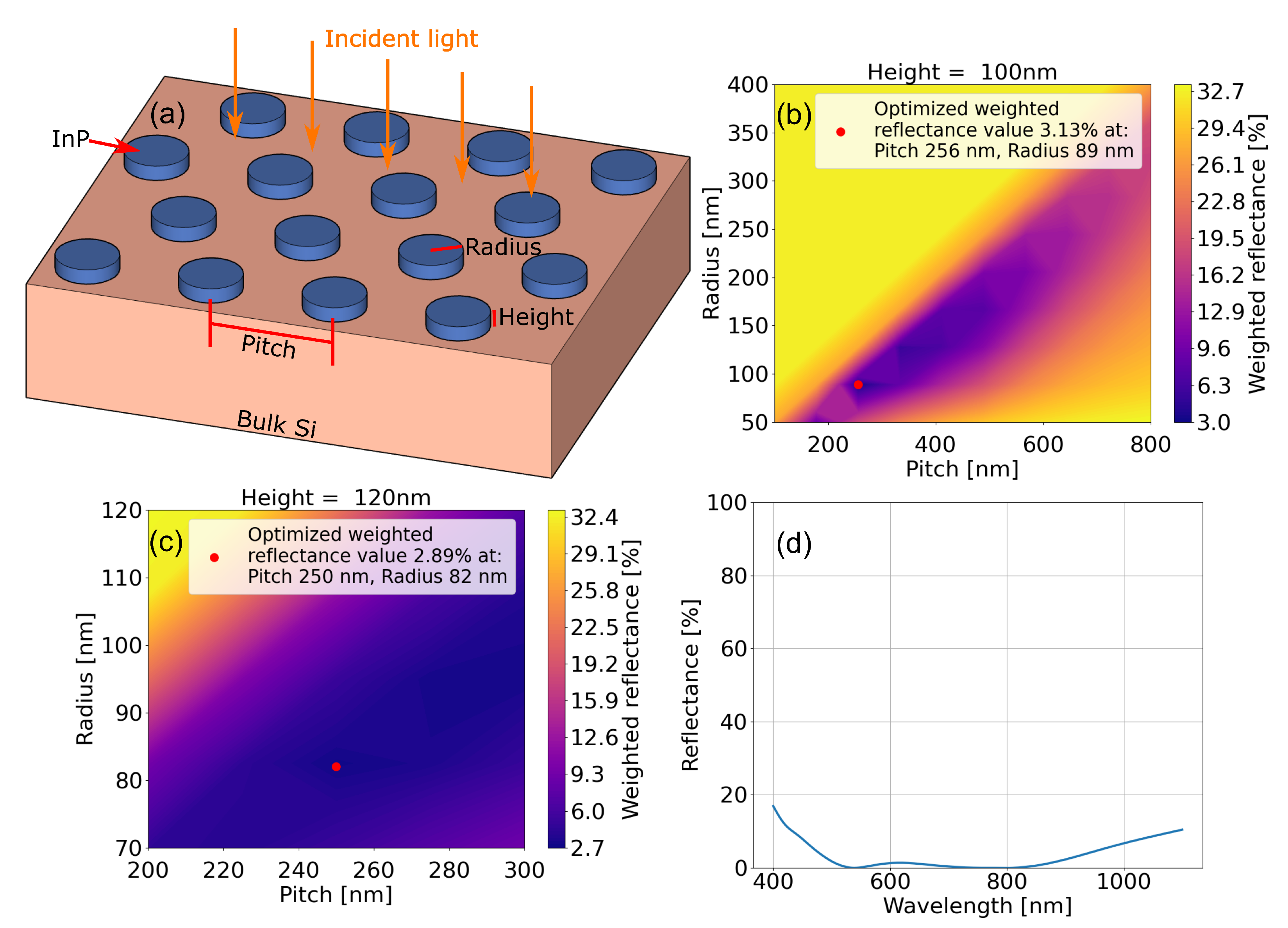
The antireflective layer consists of a hexagonal lattice of InP nanodisks placed on Si. The structure is schematically shown in Figure 2a. The light is vertically incident on the structure with forward-scattering defined into the substrate and backward scattering into air. The effect of size and pitch/period of the array of InP nanodisks on the reflectance from the substrate was studied using FDTD simulations. The height (h), radius (r), and the distance between nearest neighbors, i.e., pitch (p), were used as the varying parameters of the nanodisk array. A wavelength range of 400 nm to 1100 nm was chosen taking into account absorption in both Si and InP. A hexagonal array of nanodisks was used as the basis for the simulations as it can be reproducible in a real-world setting using colloidal lithography and dry etching techniques [45,46]. This also allows for the highest possible packing fraction of nanodisks in a 2D arrangement. However other lattices and nanostructure shapes can also be considered. A wide range parameter sweep consisting of seven heights from 100 nm to 700 nm, 10 pitches from 100 nm to 800 nm and 10 radii from 50 nm to 400 nm, amounting to 700 individual simulations were run to find reflectance minima. The simulated reflectances are weighted with the solar spectrum as:
R w = λ m i n λ m a x R ( λ ) S ( λ ) d λ λ m i n λ m a x S ( λ ) d λ
where R w is the weighted reflectance, R ( λ ) is the unweighted reflectance and S ( λ ) is the AM1.5 solar spectrum. As seen in Figure 2b, the InP nanodisk array parameters pitch: ∼260 nm, radius: ∼90 nm and height: 100 nm result in a reflectance minimum of 3.1%. The nanodisk array parameters acquired from this wide range sweep were then used as a starting point for a more detailed sweep to find the lowest reflectance. A minimum weighted reflectance of 2.9% resulted from using parameters: height 120 nm, pitch 250 nm and radius ∼80 nm, shown in Figure 2c. For reference the weighted reflectance for bulk Si in the same wavelength range is 35.3%. The unweighted reflectance of the optimized structures as a function of wavelength is shown in Figure 2d. The structures show broadband antireflective properties between 400 nm to 1100 nm.
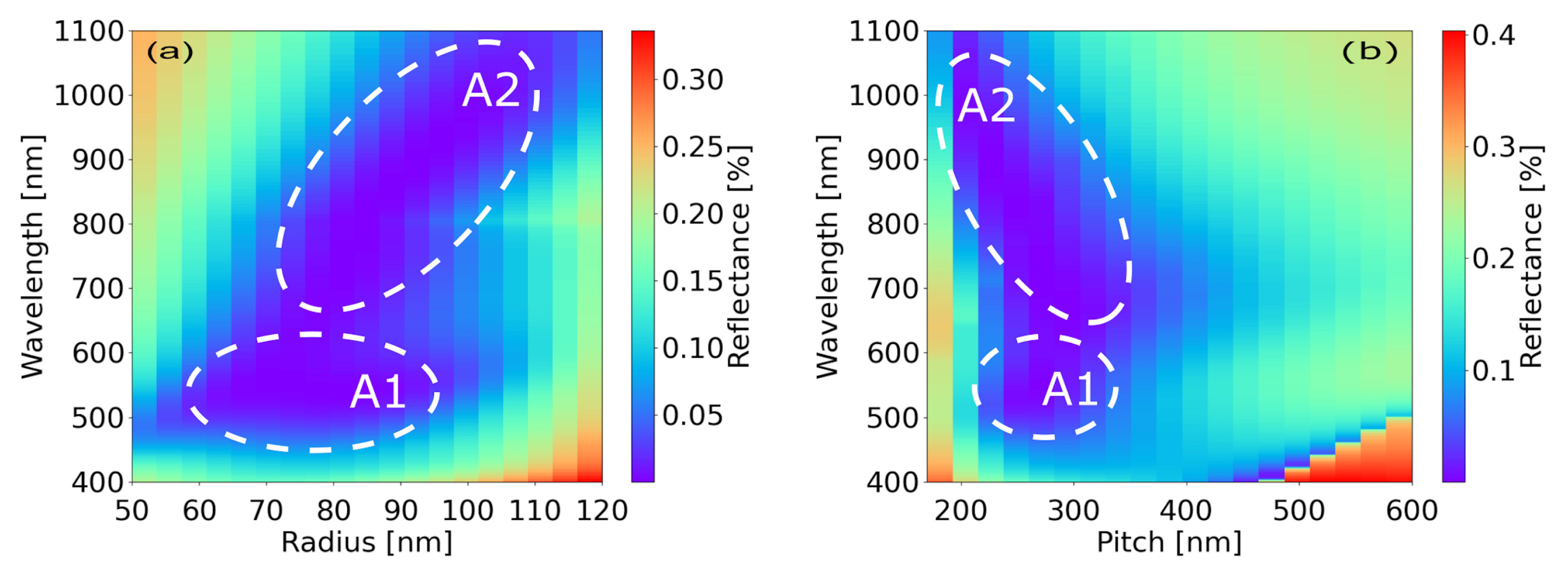
To understand how the reflectance is affected by the change in the radius and the separation of nanodisks, simulations varying these parameters close to the optimized ones were performed. With the height and pitch of the array held constant at 120 nm and 250 nm respectively, the radius was varied from 50 nm to 120 nm. Similarly, the pitch was varied from 170 nm to 600 nm while the array height was kept constant at 120 nm and radius at 82 nm. The results are depicted in Figure 3. Two distinct areas of minimal reflectance can be observed in these maps. When the radius is varied, an almost wavelength-independent area of reflectance minima can be seen in Figure 3a,b, depicted as A1. This can be accredited to a backward scattering reduction induced by a Mie type resonance in the nanodisks. Another area of minimal reflection is depicted as A2 in Figure 3a,b. The reflectance minimum red-shifts almost linearly with disk radius (Figure 3a) while it blue-shifts with the period (Figure 3b). As both increasing the radius and decreasing the pitch increase the surface fill factor of the InP nanodisks, this is an indication of index-matching by an effective index layer, consisting of both the indices of the nanodisks and the surrounding air gap, to the Si substrate.

3.2. Multipole Decomposition of the Optimized Structures

To gain further insight on how the Mie resonances affect the antireflective properties of the nanodisk array on Si, a multipole decomposition of the induced electric current densities in the structures was studied. To study the resonance contribution to the antireflective properties of the nanodisk array placed on a Si substrate, the radius of the nanodisks as well as the array pitch was varied. The multipole decomposition method described in Section 2.3 was used to calculate a backward to forward-scattering ratio with the results presented in Figure 4. In these simulations the static parameters for height, pitch, and radius were chosen as the values for the optimized nanodisk array shown in Figure 2c. The sweep parameters for both pitch and radius were chosen to cover the A1 areas seen in Figure 3a,b. For the nanodisk array, with a pitch of 250 nm and nanodisk height of 120 nm, as the nanodisk radius is varied from 60 nm to 90 nm the BFR shifts slightly towards higher wavelengths and at the same time lowered slightly. Similarly for an array with a nanodisk radius of 80 nm and height of 120 nm, as the pitch of the nanodisks is varied from 20 nm to 350 nm the BFR minima position remains stationary close to 500 nm. By comparing the effects of varying radius and pitch in Figure 4 to the results from reflectance radius and pitch sweeps presented in Figure 3, similar effects can be observed. In both cases, we observe a reflectance minimum that is almost unaffected by the varying radius and pitch of the nanodisks. The BFR is under 0.6 for the whole wavelength span which indicates that most of the light is scattered towards the Si substrate. This strengthens the assumption that the antireflective properties of the nanodisk array indeed are composed of both effects arising from Mie resonances and an effective index-matching of the InP nanodisk array to the Si substrate.

3.3. Thin-Film Effect

With the incoming light at vertical incidence, the InP nanodisk/air interface can be modeled as a thin-film coating with an effective refractive index n e f f . The n e f f is a volume-weighted average of the refractive indices of the nanodisk material and the surrounding medium and depends on the fill factor of the array. Using Equation (6) the n e f f of a thin film equivalent to the nanodisk array can be calculated.
n e f f = n s f + n i ( 1 f )
Here, n s is the refractive index of the nanodisk, n i the refractive index of the surrounding medium, in our case air ( n i = 1) and f the fill factor for a hexagonal array of disks given by
f = 2 π r 2 3 p 2
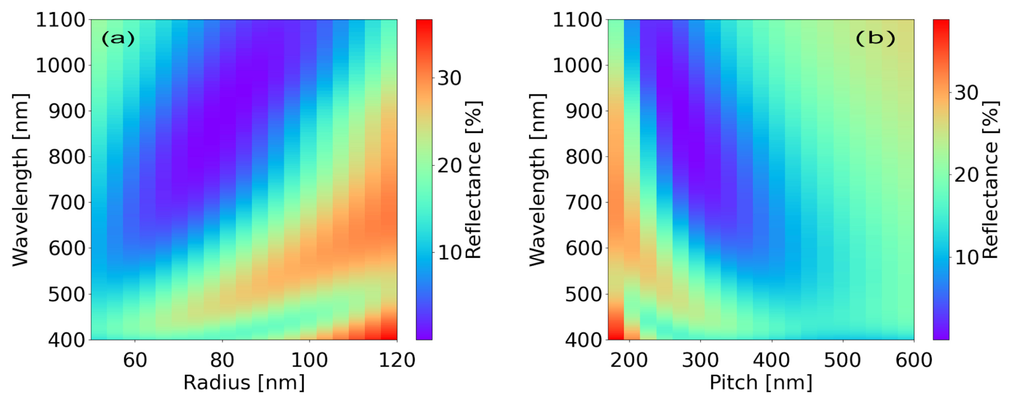
where r is the radius of the nanodisk and p is the pitch of the array. A sweep of a 120 nm thick film with a varying effective index caused by a variance in the pitch, from 170 nm to 600 nm and radius from 50 nm to 120 nm, of an InP nanodisk array on a Si surface was performed. The results presented in Figure 5 show that the wavelength positions of the reflectance minima shift almost linearly when the radius and pitch are changed, similar to the trend observed in Figure 3. These results further strengthen the hypothesis that part of the reflectance suppression is caused by an index-matching between the nanodisk array and the substrate.

3.4. Absorption Enhancement in Thin-Film Si Solar Cells by Nanodisk Arrays

To optimize the efficiency of a Si thin-film solar cell it is important that most of the optical power is absorbed in the structure. Therefore, we investigate the absorption in the Si substrate of the InP nanodisk/Si structure at depths above 2 μm. We compare the simulated absorption of the optimized InP nanodisk/Si structure to a plain Si substrate, a Si nanodisk array on a Si substrate with the same parameters as the InP nanodisk array, and a thin-film of InP on a Si substrate with a thickness equal to the nanodisk height. The surface of the Si substrate is defined to be at depth 0 and the absorption is measured at 0, 500, 1000, and 2000 nm as shown in Figure 6.
The results from the absorption simulations presented in Table 1 show that the optimized InP nanodisk/Si structure has the highest absorption at all depths compared to the other structures. At the surface of the Si substrate, the InP nanodisks have absorbed 30.8% of the incoming light compared to 30.5% in the InP thin film, even though the InP nanodisk structure has a material fill factor of ∼40% compared to the thin film. This can partly be explained through Mie-resonance enhanced absorption in the InP nanodisks and partly by the antireflective properties of the InP nanodisk array, allowing for more light to enter the material. In comparison, a plain 120 nm thick Si slab has an absorption of only 6.9%. At 500 nm into the Si substrate, the InP nanodisk/Si structure has absorbed 47.5% of the incoming optical power, of which 16.7% is absorbed in Si. At the same depth, the Si nanodisks on Si have a total absorption of 33.5% and the Si below has absorbed 25.2% of the light. The plain Si has absorbed 18.2% at this depth. The higher absorption in the Si nanodisk/Si structure compared to that of the Si slab is mainly due to the antireflective properties of the Si nanodisk array. With the parameters used the weighed reflectance was 4.9% for the Si nanodisk arrays. At 1 μm the 55% absorption in the InP nanodisk/Si structure is more than 10% higher than in the Si nanodisk/Si structure. Interestingly, at this depth, the Si nanodisk array on Si outperforms the InP thin-film/Si structures with absorptions of 44.7% and 40.2% respectively. This can again be explained by the antireflective properties of the Si nanodisk array. By reducing the reflectance, the Si nanodisk array allows for a higher percentage of transmitted optical power into the Si substrate, leading to higher absorption. The InP nanodisk/Si structure has ∼7% higher absorption than Si nanodisk/Si at a depth of 2 μm. At depths of 5 μm to 10 μm the difference diminishes as the amount of power absorbed in the Si substrate is predominately a result of the antireflective properties of the arrays. The calculated ideal short circuit current density, assuming that every absorbed photon excite an electron-hole pair and all the generated carriers contribute with no recombination losses, show an increase from 5.9 mA cm−2 for plain Si to 16.4 mA cm−2 for the InP nanodisk/Si structure at a depth of 500 nm in the Si substrate.

4. Conclusions

In this paper, the potential advantages of using InP nanodisk arrays as both an antireflective coating and absorption enhancers in a thin-film Si solar cell have been studied. The antireflective and absorption properties of InP nanodisk arrays on a Si substrate have been examined using FDTD simulations and multipole decomposition has been used to study the effect of Mie resonances on the scattering properties of the arrays. A reflectance minimum of 2.9% was found for a hexagonal InP nanodisk array on a Si substrate with parameters: height 120 nm, pitch 250 nm and radius 80 nm. Further analysis of the effect of radius and pitch on the reflectance of the optimized arrays showed two distinctive areas in the broadband reflectance minima. The origin of the antireflection was shown to arise from the collective effects of an impedance matching of the nanodisk array to the Si substrate and suppression of backward scattering due to Mie resonances in the InP nanodisks. The absorption properties of InP nanodisks were compared to Si nanodisks with the same structural parameters placed on top of a Si thin film. The InP nanodisk-covered Si film had a substantially higher absorption at all depths up to 2 μm compared to the Si nanodisk/Si structure. By enhancing the absorption near the surface of the thin-film Si solar cell the diffusion path length of created carriers to the depletion region can be reduced thus enhancing carrier collection of the cell. The higher absorption also allows for thinner Si films as most of the optical power is absorbed close to the surface of the cell. The ideal short circuit current density of the InP nanodisk/Si structure was also observed to be significantly higher compared to that of a plain Si structure. With imperfections in the InP nanodisk surfaces arising from etching processes combined with the uncertain quality of bonding to the Si substrate, recombination losses in the structures are not yet fully clear and will require further study. Although other parameters such as fill factor and external quantum efficiency are important for solar cell performance comparisons, they are not in the scope of this paper. Future work is planned for complete device simulations of the InP nanodisk/Si solar cell. The obtained results from this study are promising for thin-film InP/Si solar cell applications.

Author Contributions

Conceptualization, A.P.R. and S.A.; methodology, M.K. and A.P.R.; Code for multipole decomposition: A.P.R. and M.K.; The manuscript was written by M.K. with feedback from A.P.R. and S.A., and the results were jointly interpreted. All authors have read and agreed to the published version of the manuscript.

Funding

This research was funded by the Swedish Research Council—Vetenskapsrådet, grant number 2019-05321, and by the Swedish Energy Agency—Energimyndigheten, grant number 49227-1.

Institutional Review Board Statement

Not applicable.

Informed Consent Statement

Not applicable.

Data Availability Statement

The data presented in this study are available on request from the corresponding author.

Conflicts of Interest

The authors declare no conflict of interest.

References

  1. Bohren, C.F.; Huffman, D.R. Absorption and Scattering of Light by Small Particles; Wiley Science Series; Wiley: New York, NY, USA, 1983. [Google Scholar] [CrossRef] [Green Version]
  2. National Renewable Energy Laboratory, U.S. Department of Energy. Best Research-Cell Efficiency Chart. Available online: https://www.nrel.gov/pv/cell-efficiency.html (accessed on 2 July 2020).
  3. Nayak, P.K.; Mahesh, S.; Snaith, H.J.; Cahen, D. Photovoltaic solar cell technologies: Analysing the state of the art. Nat. Rev. Mater. 2019, 4, 269–285. [Google Scholar] [CrossRef]
  4. Green, M.A.; Dunlop, E.D.; Hohl-Ebinger, J.; Yoshita, M.; Kopidakis, N.; Ho-Baillie, A.W. Solar cell efficiency tables (Version 55). Prog. Photovolt. Res. Appl. 2020, 28, 3–15. [Google Scholar] [CrossRef]
  5. Dross, F.; Baert, K.; Bearda, T.; Deckers, J.; Depauw, V.; El Daif, O.; Gordon, I.; Gougam, A.; Govaerts, J.; Granata, S.; et al. Crystalline thin-foil silicon solar cells: Where crystalline quality meets thin-film processing. Prog. Photovolt. Res. Appl. 2012, 20, 770–784. [Google Scholar] [CrossRef]
  6. Meillaud, F.; Boccard, M.; Bugnon, G.; Despeisse, M.; Hänni, S.; Haug, F.J.; Persoz, J.; Schüttauf, J.W.; Stuckelberger, M.; Ballif, C. Recent advances and remaining challenges in thin-film silicon photovoltaic technology. Mater. Today 2015, 18, 378–384. [Google Scholar] [CrossRef]
  7. Wang, A.; Zhao, J.; Wenham, S.R.; Green, M.A. 21.5% Efficient thin silicon solar cell. Prog. Photovolt. Res. Appl. 1996, 4, 55–58. [Google Scholar] [CrossRef]
  8. Jeong, S.; McGehee, M.D.; Cui, Y. All-back-contact ultra-thin silicon nanocone solar cells with 13.7% power conversion efficiency. Nat. Commun. 2013, 4, 2950. [Google Scholar] [CrossRef] [Green Version]
  9. Hänni, S.; Bugnon, G.; Parascandolo, G.; Boccard, M.; Escarré, J.; Despeisse, M.; Meillaud, F.; Ballif, C. High-efficiency microcrystalline silicon single-junction solar cells. Prog. Photovolt. Res. Appl. 2013, 21, 821–826. [Google Scholar] [CrossRef]
  10. Depauw, V.; Trompoukis, C.; Massiot, I.; Chen, W.; Dmitriev, A.; Cabarrocas, P.R.i.; Gordon, I.; Poortmans, J. Sunlight-thin nanophotonic monocrystalline silicon solar cells. Nano Futures 2017, 1, 021001. [Google Scholar] [CrossRef]
  11. Lee, S.H.; Lee, I.; Yi, J. Silicon nitride films prepared by high-density plasma chemical vapor deposition for solar cell applications. Surf. Coat. Technol. 2022, 153, 67–71. [Google Scholar] [CrossRef]
  12. Zhao, J.; Green, M. Optimized antireflection coatings for high-efficiency silicon solar cells. IEEE Trans. Electron Devices 1991, 38, 1925–1934. [Google Scholar] [CrossRef]
  13. Macdonald, D.H.; Cuevas, A.; Kerr, M.J.; Samundsett, C.; Ruby, D.; Winderbaum, S.; Leo, A. Texturing industrial multicrystalline silicon solar cells. Sol. Energy 2004, 76, 277–283. [Google Scholar] [CrossRef] [Green Version]
  14. Winderbaum, S.; Reinhold, O.; Yun, F. Reactive ion etching (RIE) as a method for texturing polycrystalline silicon solar cells. Sol. Energy Mater. Sol. Cells 1997, 46, 239–248. [Google Scholar] [CrossRef]
  15. Atwater, H.A.; Polman, A. Plasmonics for improved photovoltaic devices. Nat. Mater. 2010, 9, 205–213. [Google Scholar] [CrossRef] [PubMed]
  16. Baryshnikova, K.V.; Petrov, M.I.; Babicheva, V.E.; Belov, P.A. Plasmonic and silicon spherical nanoparticle antireflective coatings. Sci. Rep. 2016, 6, 22136. [Google Scholar] [CrossRef] [PubMed]
  17. Deng, Y.; Cao, G.; Yang, H.; Zhou, X.; Wu, Y. Dynamic Control of Double Plasmon-Induced Transparencies in Aperture-Coupled Waveguide-Cavity System. Plasmonics 2018, 13, 345–352. [Google Scholar] [CrossRef]
  18. Zheng, Z.; Zheng, Y.; Luo, Y.; Yi, Z.; Zhang, J.; Liu, Z.; Yang, W.; Yu, Y.; Wu, X.; Wu, P. A switchable terahertz device combining ultra-wideband absorption and ultra-wideband complete reflection. Phys. Chem. Chem. Phys. 2022, 24, 2527–2533. [Google Scholar] [CrossRef]
  19. van Lare, C.; Lenzmann, F.; Verschuuren, M.A.; Polman, A. Dielectric Scattering Patterns for Efficient Light Trapping in Thin-Film Solar Cells. Nano Lett. 2015, 15, 4846–4852. [Google Scholar] [CrossRef]
  20. Daqiqeh Rezaei, S.; Dong, Z.; You En Chan, J.; Trisno, J.; Ng, R.J.H.; Ruan, Q.; Qiu, C.W.; Mortensen, N.A.; Yang, J.K. Nanophotonic Structural Colors. ACS Photonics 2021, 8, 18–33. [Google Scholar] [CrossRef]
  21. Yang, W.; Xiao, S.; Song, Q.; Liu, Y.; Wu, Y.; Wang, S.; Yu, J.; Han, J.; Tsai, D.P. All-dielectric metasurface for high-performance structural color. Nat. Commun. 2020, 11, 1864. [Google Scholar] [CrossRef] [Green Version]
  22. Cai, J.; Qi, L. Recent advances in antireflective surfaces based on nanostructure arrays. Mater. Horizons 2014, 2, 37–53. [Google Scholar] [CrossRef]
  23. Peter Amalathas, A.; Alkaisi, M.M. Nanostructures for Light Trapping in Thin Film Solar Cells. Micromachines 2019, 10, 619. [Google Scholar] [CrossRef] [PubMed] [Green Version]
  24. Adibzadeh, F.; Olyaee, S. Plasmonic Enhanced InP Nanowire Array Solar Cell through Optoelectronic Modeling. Photonics 2021, 8, 90. [Google Scholar] [CrossRef]
  25. Raj, V.; Rougieux, F.; Fu, L.; Tan, H.H.; Jagadish, C. Design of Ultrathin InP Solar Cell Using Carrier Selective Contacts. IEEE J. Photovolt. 2020, 10, 1657–1666. [Google Scholar] [CrossRef]
  26. Yin, X.; Battaglia, C.; Lin, Y.; Chen, K.; Hettick, M.; Zheng, M.; Chen, C.Y.; Kiriya, D.; Javey, A. 19.2% Efficient InP Heterojunction Solar Cell with Electron-Selective TiO2 Contact. ACS Photonics 2014, 1, 1245–1250. [Google Scholar] [CrossRef] [PubMed] [Green Version]
  27. Yamaguchi, M.; Yamamoto, A.; Uchida, N.; Uemura, C. A new approach for thin film InP solar cells. Sol. Cells 1986, 19, 85–96. [Google Scholar] [CrossRef]
  28. Kroemer, H.; Liu, T.Y.; Petroff, P.M. GaAs on Si and related systems: Problems and prospects. J. Cryst. Growth 1989, 95, 96–102. [Google Scholar] [CrossRef]
  29. Sugo, M.; Takanashi, Y.; Al-jassim, M.M.; Yamaguchi, M. Heteroepitaxial growth and characterization of InP on Si substrates. J. Appl. Phys. 1990, 68, 540–547. [Google Scholar] [CrossRef]
  30. Shimizu, Y.; Okada, Y. Growth of high-quality GaAs/Si films for use in solar cell applications. J. Cryst. Growth 2004, 265, 99–106. [Google Scholar] [CrossRef]
  31. Lourdudoss, S. Heteroepitaxy and selective area heteroepitaxy for silicon photonics. Curr. Opin. Solid State Mater. Sci. 2012, 16, 91–99. [Google Scholar] [CrossRef]
  32. Tanabe, K.; Watanabe, K.; Arakawa, Y. III-V/Si hybrid photonic devices by direct fusion bonding. Sci. Rep. 2012, 2, 349. [Google Scholar] [CrossRef]
  33. Roelkens, G.; Liu, L.; Liang, D.; Jones, R.; Fang, A.; Koch, B.; Bowers, J. III-V/silicon photonics for on-chip and intra-chip optical interconnects. Laser Photonics Rev. 2010, 4, 751–779. [Google Scholar] [CrossRef]
  34. Pantzas, K.; Itawi, A.; Sagnes, I.; Patriarche, G.; Le Bourhis, E.; Lupu, A.; Benisty, H.; Talneau, A. Oxide-Free Bonding of III-V-Based Material on Silicon and Nano-Structuration of the Hybrid Waveguide for Advanced Optical Functions. Photonics 2015, 2, 1054–1064. [Google Scholar] [CrossRef] [Green Version]
  35. Pasquariello, D.; Camacho, M.; Hjort, K.; Dózsa, L.; Szentpáli, B. Evaluation of InP-to-silicon heterobonding. Mater. Sci. Eng. B 2001, 80, 134–137. [Google Scholar] [CrossRef]
  36. Rühle, S. Tabulated values of the Shockley–Queisser limit for single junction solar cells. Sol. Energy 2016, 130, 139–147. [Google Scholar] [CrossRef]
  37. Hoffman, C.A.; Gerritsen, H.J.; Nurmikko, A.V. Study of surface recombination in GaAs and InP by picosecond optical techniques. J. Appl. Phys. 1980, 51, 1603–1604. [Google Scholar] [CrossRef]
  38. Nolte, D.D. Surface recombination, free-carrier saturation, and dangling bonds in InP and GaAs. Solid-State Electron. 1990, 33, 295–298. [Google Scholar] [CrossRef]
  39. Naureen, S.; Shahid, N.; Dev, A.; Anand, S. Generation of substrate-free III–V nanodisks from user-defined multilayer nanopillar arrays for integration on Si. Nanotechnology 2013, 24, 225301. [Google Scholar] [CrossRef] [Green Version]
  40. Lumerical FDTD Solutions. Available online: https://www.lumerical.com/ (accessed on 13 September 2020).
  41. Sze, S.M.; Ng, K.K. p-n Junctions. In Physics of Semiconductor Devices; John Wiley & Sons, Ltd.: Hoboken, NJ, USA, 2006; pp. 124–129. [Google Scholar] [CrossRef]
  42. Alaee, R.; Rockstuhl, C.; Fernandez-Corbaton, I. An electromagnetic multipole expansion beyond the long-wavelength approximation. Opt. Commun. 2018, 407, 17–21. [Google Scholar] [CrossRef] [Green Version]
  43. Alaee, R.; Filter, R.; Lehr, D.; Lederer, F.; Rockstuhl, C. A generalized Kerker condition for highly directive nanoantennas. Opt. Lett. 2015, 40, 2645–2648. [Google Scholar] [CrossRef]
  44. Pors, A.; Andersen, S.K.H.; Bozhevolnyi, S.I. Unidirectional scattering by nanoparticles near substrates: Generalized Kerker conditions. Opt. Express 2015, 23, 28808–28828. [Google Scholar] [CrossRef] [Green Version]
  45. Naureen, S.; Sanatinia, R.; Shahid, N.; Anand, S. High Optical Quality InP-Based Nanopillars Fabricated by a Top-Down Approach. Nano Lett. 2011, 11, 4805–4811. [Google Scholar] [CrossRef] [PubMed]
  46. Zhang, C.; Cvetanovic, S.; Pearce, J.M. Fabricating ordered 2-D nano-structured arrays using nanosphere lithography. MethodsX 2017, 4, 229–242. [Google Scholar] [CrossRef] [PubMed]
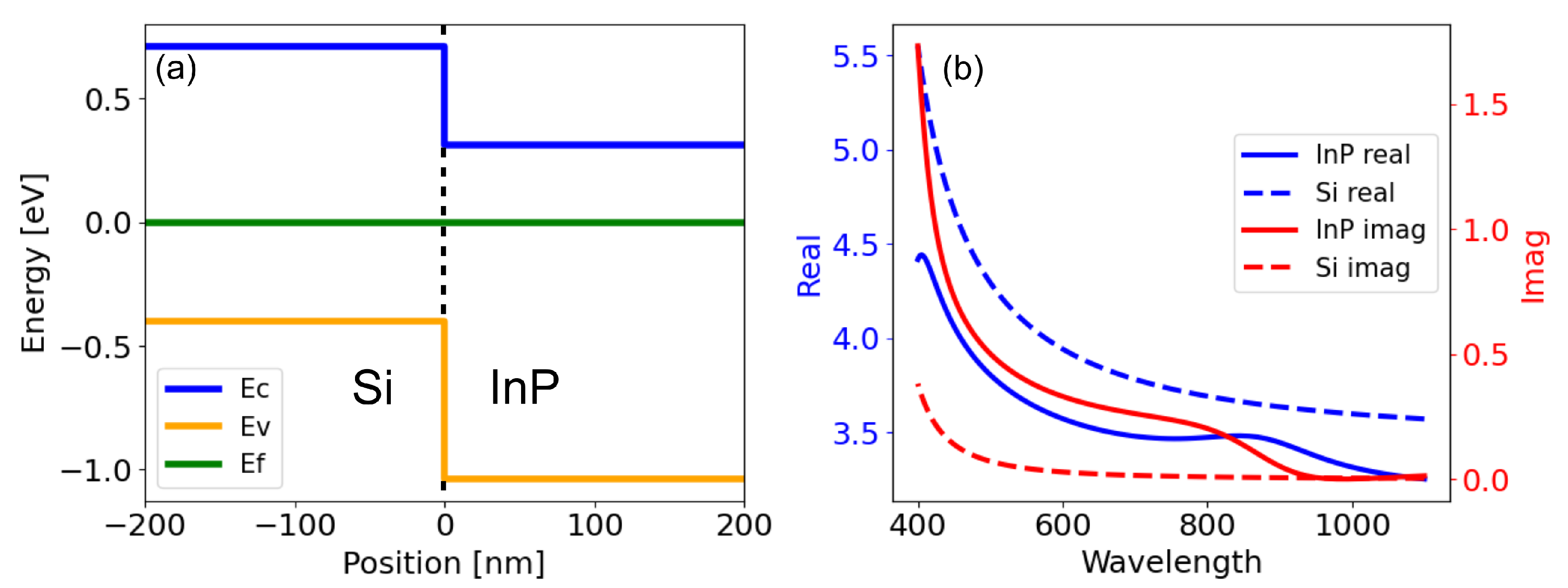
Figure 1. (a) Energy band diagram of a InP/Si heterojunction showing the type-II band alignment. Energy levels of the conduction band (Ec), valence band (Ev) and Fermi level (Ef) are depicted by the blue, orange and green lines, respectively. (b) Real and imaginary parts of the refractive indices of InP and Si used in the simulations.
Photonics 09 00157 g001
Figure 2. Optimization of weighted reflectance of InP nanodisks on a Si substrate. (a) Schematic of the structure with relevant array parameters pitch, height, and radius. The incident light is depicted in yellow. A rough optimization shown in (b) and the final optimized reflectance and nanodisk array parameters shown in (c). All parameters were varied in the sweeps but only the results from the optimized heights are shown. (d) Reflectance of the optimized InP nanodisk/Si structure.
Photonics 09 00157 g002
Figure 3. Reflectance of InP nanodisks on a Si substrate as a function of radius (a), pitch (b) and wavelength. A1 shows an area of minimal reflectance due to Mie type resonances in the structures and A2 minimal reflectance due to the effective refractive index impedance matching.
Photonics 09 00157 g003
Figure 4. The effect on BFR of radius (a) and pitch (b) of the nanodisk array. Suppressed backward scattering can be observed at ∼550 nm in both (a,b). Variations in radius and pitch show a small effect on the BFR minima position.
Photonics 09 00157 g004
Figure 5. The effect of varying radius (a) and pitch (b) of the reflectance of a hexagonal InP array on a Si substrate with a InP nanodisk height of 120 nm.
Photonics 09 00157 g005
Figure 6. Absorption simulation setup for nanodisk and thin-film structures. The investigated nanodisk arrays and InP thin film are depicted in red on top of a bulk Si substrate (black). Absorption of all structures is measured in the Si substrate at depths of 0, 500, 1000 and 2000 nm.
Photonics 09 00157 g006
Table 1. Absorption in % at different depths in the Si substrate with different structures as top layer. Nanodisk array parameters for all different setups are: radius 80 nm, pitch 250 nm (hexagonal array) and height 120 nm.
Absorption Depth [nm]Plain SiInP Thin Film/SiSi Nanodisks/SiOptimized InP Nanodisks/Si
00%30.5%8.3%30.8%
50018.2%36.9%33.5%47.5%
100025.9%40.2%44.7%55.0%
200034.6%44.7%56.7%63.6%
Publisher’s Note: MDPI stays neutral with regard to jurisdictional claims in published maps and institutional affiliations.