Article

Effect of Transmission-Line Contact Length on the 50-Gbit/s Data Encoding Performance of a Multimode VCSEL

1
Graduate Institute of Photonics and Optoelectronics and The Department of Electrical Engineering, National Taiwan University, Taipei 10617, Taiwan
2
Berxel Photonics Inc., Shenzhen 518071, China
3
Research Center for Advanced Science and Technology, University of Tokyo, Tokyo 153-0041, Japan
*
Author to whom correspondence should be addressed.
Photonics 2022, 9(2), 114; https://doi.org/10.3390/photonics9020114
Submission received: 27 January 2022 / Revised: 14 February 2022 / Accepted: 14 February 2022 / Published: 17 February 2022
(This article belongs to the Special Issue Vertical-Cavity Surface-Emitting Lasers (VCSELs))

Abstract

:
Directly modulated 850-nm multimode vertical-cavity surface-emitting lasers (MM-VCSELs) with different oxide apertures and transmission microstrip lengths are compared on the transmission performance of the non-return-to-zero on-off keying (NRZ-OOK) and four-level pulse amplitude modulation (PAM-4) data formats. In this work, intrinsic and extrinsic responses of the MM-VCSEL are also discussed concurrently. By tuning the length of the transmission microstrip in VCSEL, the low reflection coefficient and the enhanced 3-dB modulation bandwidth are achieved. The inductance of the transmission microstrip in the series connection with the capacitance in the active region is optimized to reduce the power loss induced by imaginary impedance. The different oxide aperture sizes for MM-VCSEL are also studied to control the capacitance and photon density. More importantly, the 3-dB modulation bandwidth, impedance matching, slope efficiency, relative intensity noise (RIN), and mode partition noise (MPN) for the MM-VCSEL with various designs are discussed to determine the best device with the high-speed transmission capability. The optimal MM-VCSEL with a diameter of 7 µm oxide aperture and a length of 25 µm transmission microstrip successfully demonstrates 50-Gbit/s OOK and 84-Gbit/s PAM4 after using the pre-emphasis technique for future data-center applications.

1. Introduction

Recently, the demands for streaming high-definition videos and interactive-reality programs have increased year by year. The total number of internet users will enlarge to 5.3 billion in 2023 with a growth ratio improving from 51 to 66% of the global population compared to 2018 [1]. The photonic module integrates with the electrical integrated circuit for a highly compact and energy-efficient transceiver with more bits needed for high-performance computing. Because of the attractive features of vertical-cavity surface-emitting lasers (VCSELs), including low power consumption, modulation by the low current, high conversion efficiency, low divergence angle, high reliability, and easy-coupling by fiber, the optical network with directly modulated 850-nm VCSEL and multimode fiber (MMF) becomes a standard solution for short-reach data transmission [2,3,4,5,6,7,8,9,10]. According to the latest 800 G specification proposed by the Ethernet technology consortium, the 800GBASE-R based on Clause 119 of IEEE Std 802.3 operates at a data rate of 800 Gbit/s. The 800 G ethernet technology is defined as an interface using eight 106 Gbit/s lanes by a 2xClause 119 PCSs (Physical Coding Sublayer) to connect a single media access control (MAC) operating at 800 Gbit/s [11]. Therefore, the optimization of the VCSEL design becomes a popular research topic further to achieve a data rate of 106 Gbit/s per lane.
The first oxide-confined VCSELs with sub-mA threshold current have been implemented for multi-Gigabit energy-efficient optical links [12,13,14,15]. Several novel fabrications are discussed for enhancing the 3 dB bandwidth of the VCSEL-based optical transceiver module in high-speed transmission [16]. Some approaches like the differential gain enhancement by strained multiple quantum well (MQW), the low K passivation, the detuned distributed Bragg reflector (DBR), the electrical parasitic limitation, and the effective thermal dissipation have been proposed to enhance the transmission performance of the VCSELs in recent years [17,18,19,20,21,22,23,24]. In addition, MQW and separate confinement heterostructure in the active layer will increase the differential gain and gain compression factor. This effect can enhance the confinement capabilities of light and electric fields in the active layer [17]. The modulation bandwidth of VCSEL is intrinsically related to the differential gain of the quantum wells in the active layer. Both quantum confinement and strained quantum wells can provide a higher differential gain [18]. In addition to selecting the laser wavelength for managing the differential gain [19], reducing parasitic resistors and capacitors associated with the structure and geometry of the VCSEL is necessary. These resistors and capacitors can form low-pass filtering to limit the modulation bandwidth [20]. A low-dielectric material passivation layer can effectively reduce the parasitic capacitance of the VCSEL to induce a higher 3-dB modulation bandwidth [21]. By increasing the aluminum fraction of the first several p-DBRs, deep oxidation layers are simultaneously produced with the oxide aperture. The equivalent capacitor thickness increases by deep oxidation layers to reduce the capacitance [22]. In addition, the thermal effect plays a vital role in high-speed transmission. The decreased thermal impedance can improve the 3-dB modulation bandwidth of VCSEL [23]. A gradually doped and graded DBR scheme is also utilized to achieve higher injection densities before the thermal rollover effect occurs. Westberge et al. demonstrated error-free transmission up to 44 Gbit/s using the VCSEL with 7-μm-oxide-confined aperture at room temperature [24].
In addition to the 3-dB modulation bandwidth, the modal dispersion also limits the transmission performance with the transmission distance [25,26]. Reducing the numbers of the transverse mode by a spatial filter of oxide aperture can achieve single-mode VCSELs. The single-mode VCSELs successfully deliver 32 Gbit/s over up to 300 m in OM4 MMF [25]. Furthermore, the relative intensity noise (RIN) and mode partition noise (MPN) of VCSELs also degrade the SNR of the signal to limit the high-speed capacity [27,28,29,30,31]. The gain competition between overlapped transverse modes can introduce the noise to further degrade the transmission capacity. In contrast, the multimode (MM-) VCSELs exhibit a mature fabrication process with larger output power and lower mode-partition noise under incomplete coupling. It is more comprehensively utilized as the main-stream transmitter toward IEEE 802.3 cm standard with less concern on the fiber coupling efficiency during the pigtailed package. Moreover, different coplanar microstrip transmission lines have been employed as the standard electrical wiring structure for the VCSELs. Their simple design is compatible with microwave circuits and easily fabricated using photolithography. The ground-signal (GS) coplanar stripline (CPS) structure exhibits lower parasitic capacitance and smaller contact-pad size in comparison with the ground-signal-ground (GSG) coplanar-waveguide design. However, the effect of parasitic inductance induced by the microstrip-line length on the high-speed response of VCSELs was seldom studied for optimization previously.
In this work, the extrinsic response of the MM-VCSEL by adjusting transmission microstrip lengths is discussed for the first time. The innate response of the MM-VCSEL dominated by the capacitance in the active region is also investigated by controlling the oxidation aperture size. According to the proposed parasitic network [32], the simplified equivalent circuit of VCSELs is simulated to analyze their frequency response and discuss the impact of different designs. Furthermore, the RF signal reflection and the D factor induced by the impedance mismatching are interpreted to indicate the modulation efficiency of the intrinsic MM-VCSEL. Finally, the RIN and MPN of the MM-VCSELs with the optimal design can be observed in this work. The operating condition of the MM-VCSEL is optimized by the Q factor from the eye diagram. After implementing the pre-emphasis technology [33], the 50 Gbit/s non-return-zero on-off keying (NRZ-OOK) transmission under the telecom criterion and the 42 Gbaud/s 4-level pulse amplitude modulation (PAM-4) transmission under the KP4-FEC standard can be successfully demonstrated.

2. Experimental Setup

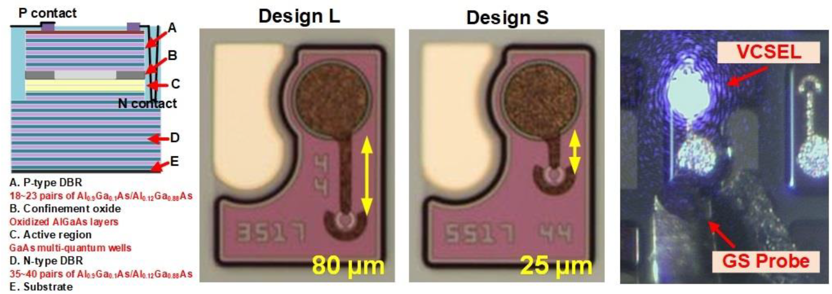
2.1. Oxide Confined MM-VCSEL with Transmission Microstrip

The cross-sectional structure of the high-speed 850-nm MM-VCSEL is shown in the left part of Figure 1. From top to bottom design, the MM-VCSEL contains the p++-type GaAs contact layer, the p-type top DBR layer with 18~23 Al0.9Ga0.1As/Al0.12Ga0.88As pairs, the 98% AlGaAs oxidation layer, the InGaAs MQW active region, the n-type bottom DBR layer with 35~40 Al0.9Ga0.1As/Al0.12Ga0.88As pairs, and the n-GaAs buffer layer. The p-type metal contact is landed on the p++-type GaAs contact layer. In terms of fabrication, the Ti/Au alloy was used to form the p-typed metallic contact with a ring shape. After deep dry etching, the Ge/Au was deposited on the n-substrate to form the n-typed metallic contact. A wet-oxidized 98% AlGaAs layer defines the VCSEL aperture sizes of 7 and 7.5 μm. A benzocyclobutene (BCB) layer was employed under the p-typed contact pad to reduce pad capacitance. The pad dimension of both the p-typed and n-typed contacts is 65 μm in diameter. The MM-VCSELs are fabricated on a 6-inch wafer with excellent uniformity. The thickness of the backside substrate was thinning to 150 μm via a mechanical polisher after finishing the whole device fabrication procedure. For improving the modulation bandwidth of the MM-VCSEL, the microstrip transmission line is employed as the access line connection between the pad and the p-type metal contact of VCSEL to reduce the limitation of the low-pass filter induced by the substrate parasitic capacitance. Moreover, the metallic GS CPS electrodes with reduced parasitic capacitance are employed to reduce the chip size. Indeed, the connection line length and the contact pad size of the VCSEL should be carefully designed to match the impedance between the VCSEL and driving circuit, which should be short and small typically if both the VCSEL and the driving circuit exhibit a characteristic impedance of 50 ohm. Nevertheless, the connected line and contact pad can be designed with a buffered or tapered impedance if there is an impedance mismatch in between, which can effectively reduce the feedback of the data signal to increase the modulation efficiency and decrease the power consumption. Although the transmission line length and contact pad area should be as small as possible when considering the parasitic circuit effect and the impedance matching issue, the contact design used in our device including the shortest transmission line length of 20 mm and smallest contact diameter of 65 mm are also considered the bonding safety. Such a 20-mm separation between device and pad guarantees the device sufficiently away from the boding pin and the pad size allows at least 2~3 times of bonding (in case of unsuccessful bonding between Au wire and contact pad with bad adhesion). The right part of Figure 1 exhibits the microscope image of the top surface of MM-VCSEL, in which different GS CPS lines with different lengths are utilized to connect with an Au guard-ring and the circular pad. For the MM-VCSELs with L- and S-type designs, the transmission line lengths are respectively set as 80 and 25 µm. The aperture diameters of the MM-VCSELs with long- and short-type designs are varied to 7 and 7.5 µm to simultaneously analyze the intrinsic and extrinsic responses of the MM-VCSELs. Furthermore, the transmission performances of the NRZ-OOK and PAM-4 data formats are compared in these MM-VCSELs with four designs.

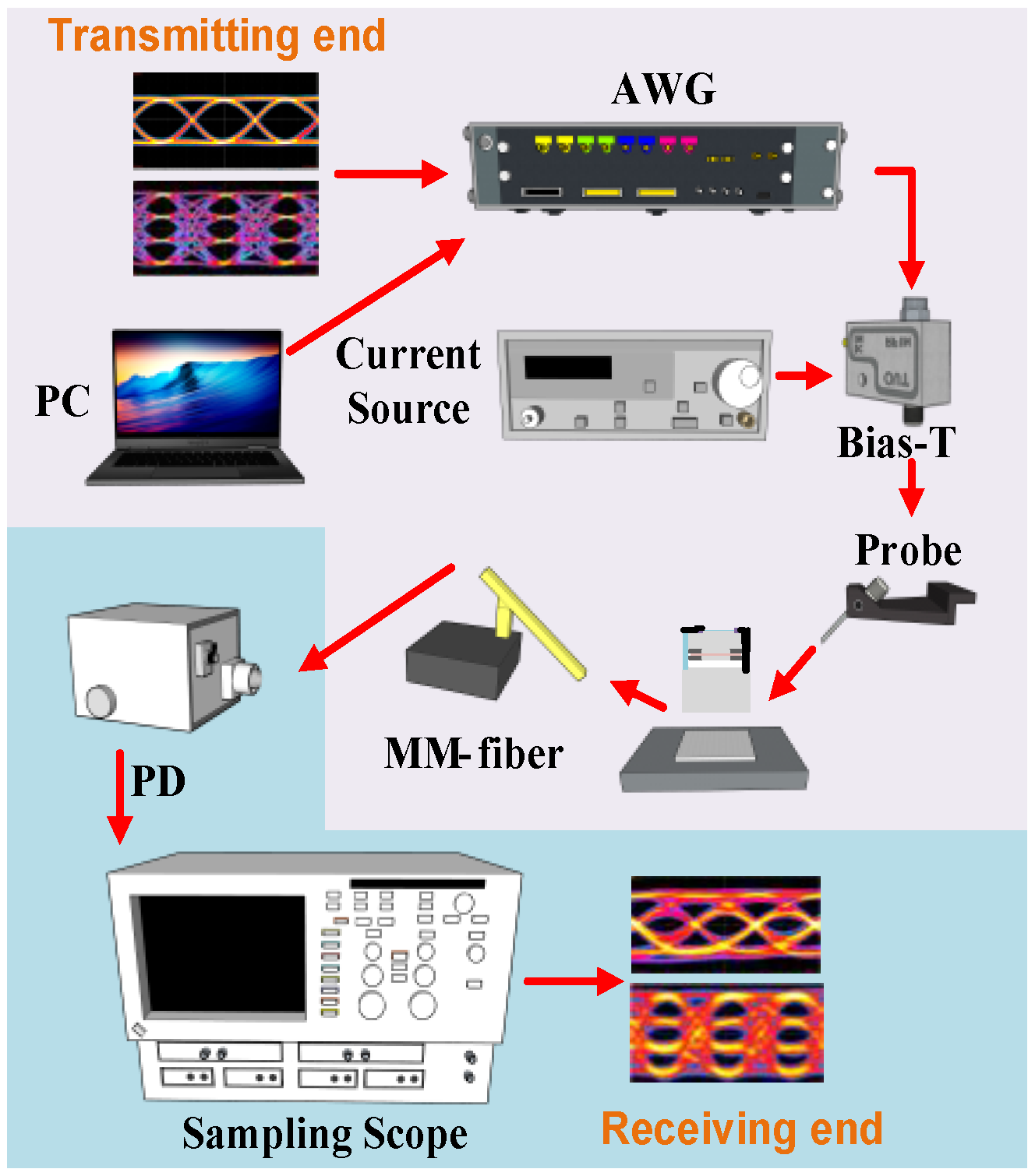
2.2. Experimental Setup of the Data Transmission System

Figure 2 shows the transmission system for the MM-VCSEL carrying with NRZ-OOK and PAM-4 data formats. An arbitrary waveform generator (AWG, Keysight M8194A, Santa Rosa, CA, USA) with a sampling rate of 120 GS/s generated the electrical NRZ-OOK and PAM-4 signals at the transmitting end. A bias-tee (Anritsu, V250, Atsugi City, Japan) with an analog bandwidth of 65-GHz was employed to combine with the DC bias current supplied by a laser diode controller (ILX Lightwave, LDX-3210, Bozeman, MT, USA) and the electrical data synthesized from an AWG. The bias-tee was connected to a microwave probe via a 40-GHz microwave cable with a length of 85 cm. A 40-GHz broadband ground-signal (GS) microwave probe (GGB, 40A-GS-125-DP, Naples, FL, USA) with a pitch interval of 125 µm was used to drive the MM-VCSEL for direct modulation. Then, the MM-VCSEL temperature was precisely controlled at 20 °C by using the liquid-cooling system (Deryun, DFC-4PT03, Taichung City, Taiwan) to stabilize the laser performance. At the receiving end, a photodetector (PD, New Focus 1484-A-50) with an analog bandwidth of 22 GHz was employed for converting the optical signal collected by a lensed MMF to the electrical signal. The lensed OM4-MMF (Corning 50/125 μm) with its length of 1 m, spot size of 20 μm, and radius of curvature of 45 μm is used in this work. The converted electrical signals were received by a digital serial analyzer (DSA, Tektronix 8300). Finally, the received waveform was analyzed to decode the bit-error-ratios (BERs) of NRZ-OOK and PAM-4 signals by the demodulated software (Tektronix, 80SJNB, Beaverton, OR, USA) built in the DSA. The BERs of the NRZ-OOK and PAM-4 data are measured by the commercial software (Tektronix, 80JARB and 80SJNB) [34]. The pseudorandom binary sequence (PRBS) length is set as 217-1. In the 80JARB and 80SJNB software, the average BER is obtained from the BERs of the horizontal and vertical bathtub curves.

3. Results

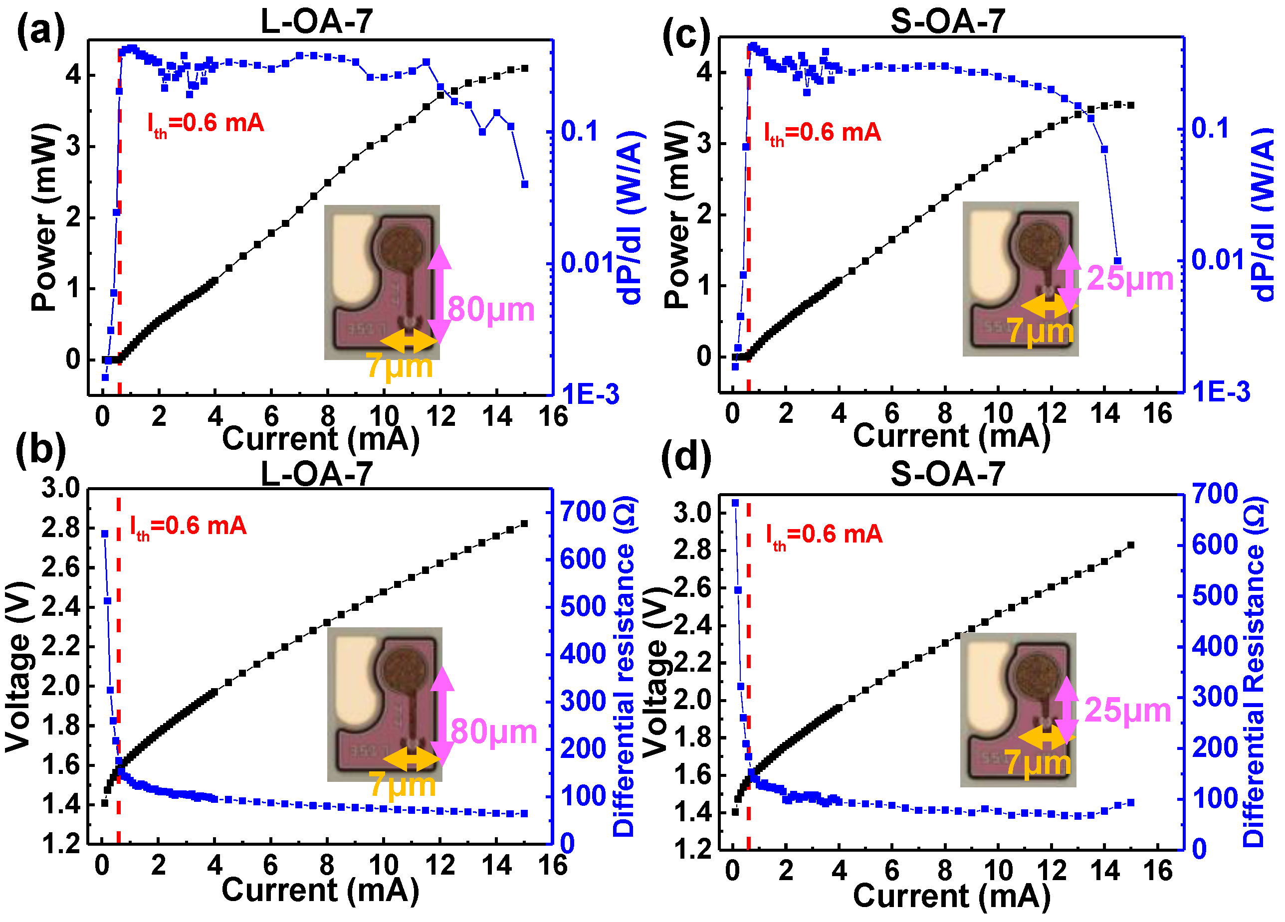
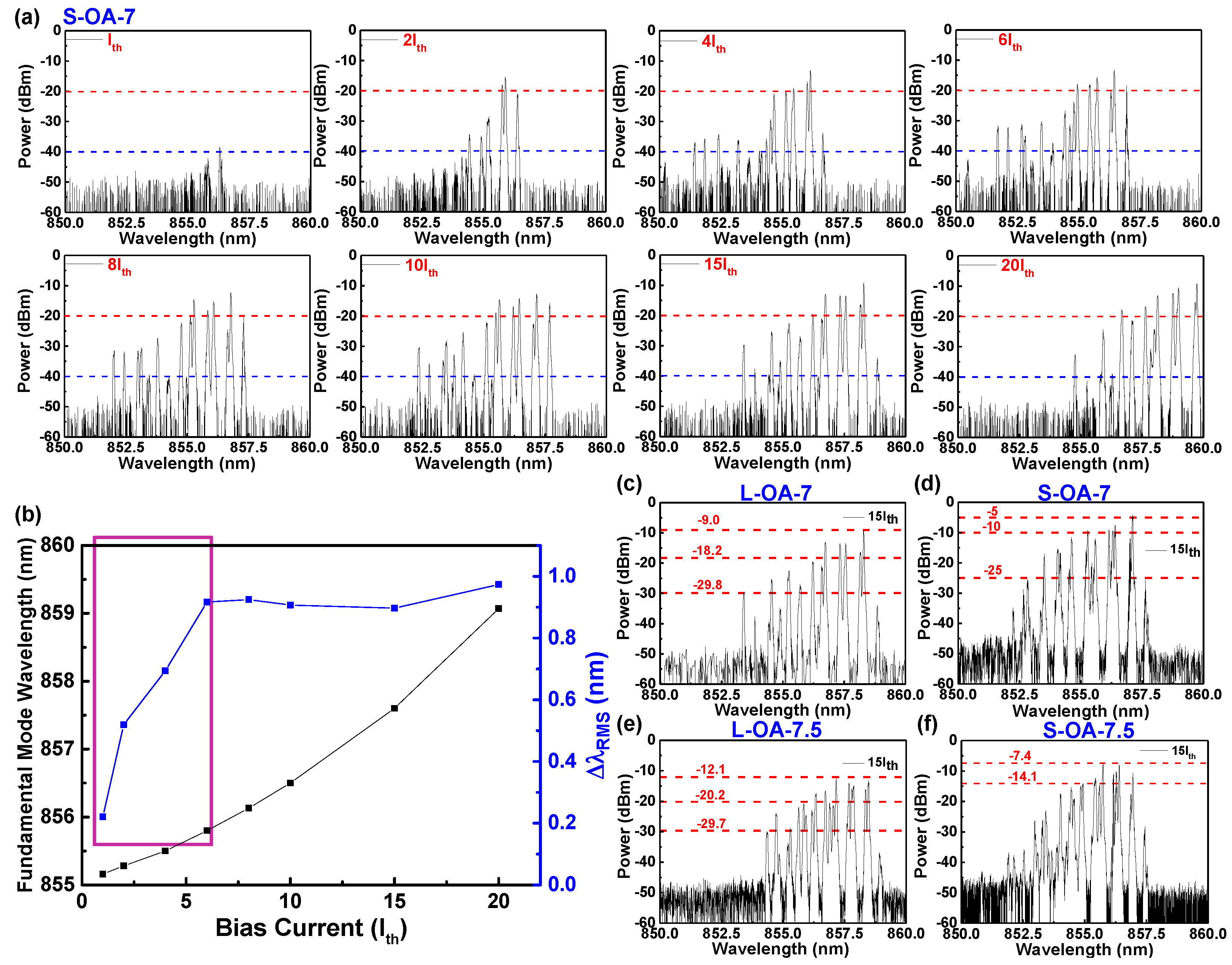
3.1. Characteristics of MM-VCSELs in Four Designs

The power-to-current (P-I) curve and dP/dI slope of the MM-VCSEL with the design of L-OA-7 are shown in Figure 3a. The MM-VCSEL with the design of L-OA-7 exhibits a threshold current of 0.6 mA and maximal optical output power of 4.1 mW before the Auger effect significantly reduces the radiative emission quantum efficiency. The voltage-to-current (V-I) curve and the differential resistance for MM-VCSEL with the design of L-OA-7 are also depicted in Figure 3b. The differential resistance of 80.3 Ω is obtained by the first-order derivative of the voltage with respect to the current. In addition, the threshold current of 0.6 mA and the maximal optical output power of 3.5 mW are obtained for MM-VCSEL with the design of S-OA-7, as shown in Figure 3c. The differential resistance of 76.4 Ω for MM-VCSEL with the design of S-OA-7 is calculated from the V-I curve in Figure 3d. From the abovementioned description, the MM-VCSELs with the designs of L-OA-7 and S-OA-7 have similar slope efficiency. The summary for the basic characteristic parameters of the MM-VCSELs with four designs is listed in Table 1. Due to the difference in the oxide aperture of the MM-VCSELs, the MM-VCSEL with an oxide aperture of 7 µm (OA-7) has a higher photon density than that with an oxide aperture of 7.5 µm (OA-7.5) under the same operating current. Therefore, the MM-VCSEL with the design of OA-7 exhibits a lower threshold current because the smaller oxide aperture limits the current direction to enhance the larger current density. Furthermore, the MM-VCSEL with the design of OA-7 has a thicker oxide aperture to increase the internal serial resistance, which further enlarges the larger differential resistance. Also, the optical output power and slope efficiency of the MM-VCSELs with the larger oxide aperture are higher than those with the smaller oxide aperture because of the different photon mode volumes for the MM-VCSEL with the various designs.
The differential quantum efficiency (ηed) can be defined as ηed = (q/) (dPout/dIbias) where q, h, ν, Pout, and Ibias, respectively denote the electron charge, the Planck constant, the frequency, the output power, and the biased current. The differential quantum efficiency of the MM-VCSELs with four designs of L-OA-7/L-OA-7.5/S-OA-7/S-OA-7.5 can be calculated as 0.18/0.32/0.17/0.25 from the dP/dI slope. The resistance of the MM-VCSEL with the L-type design is larger than that with the S-type design because of the larger serial resistance induced by the longer transmission line in the MM-VCSEL with the L-type design. Generally, the characteristic impedance (ZRF) in the microwave circuits is set as 50 Ω.
When the resistance at the load end is not 50 Ω to generate the impedance mismatch, this phenomenon will cause the signal reflection to degrade the transmission performance. The reflection coefficient (Γ) of the MM-VCSEL can be represented as Γ = (ZVCSELZRF)/(ZVCSEL + ZRF) with the ZVCSEL denoting the impedance of the MM-VCSEL. The reflection coefficients of the MM-VCSELs with different designs of L-OA-7/L-OA-7.5/S-OA-7/S-OA-7.5 are respectively obtained as 0.23/0.18/0.20/0.15 from their differential resistances by using the abovementioned formula. With defining the voltage standing wave ratio (VSWR) as VSWR = (1 + Г)/(1 − Г) and the return loss (RL) as RL = −20log|Г|, the corresponding VSWR and return loss for the MM-VCSEL with four designs of L-OA-7/L-OA-7.5/S-OA-7/S-OA-7.5 can be respectively evaluated as 1.59/1.44/1.5/1.35 and 12.7/14.9/14.0/16.5 dB. The greater return loss leads to little signal reflection, which easily maintains the transmission performance.
The optical spectra of the MM-VCSEL with the design of S-OA-7 under different biased currents from Ith to 20Ith are presented in Figure 4a. In our work, the wavelength resolution of the OSA (Ando, AQ6317B) is set as the limited resolution of 0.01 nm. From Figure 4a, the numbers of the red-shifted lasing modes for the MM-VCSEL under the biased current below 5Ith are few because of the less thermal effect induced by the current injection. Because the effective refractive index in the oxide region is lower than the core region, the high-order mode of MM-VCSEL will appear at the short-wavelength region in Figure 4a. The mode spacing can be represented as [35]:
Δ n e f f n e f f = Δ λ λ ,
where neff denotes the average effective refractive index in the central part before oxidation; Δneff the difference in effective index between the core and the oxidation region; Δλ mode spacing; λ the resonance wavelength. Increasing the bias current enlarges the high-order transverse modes at the short-wavelength region to induce the wider root-mean-square (RMS) spectral. When the bias current increases beyond 5Ith, the thermal effect becomes larger to lead the more energy conversion to phonons in the quantum well, which further contributes to the redshift of the overall wavelength. The fundamental mode wavelength and the RMS spectral width of the MM-VCSEL with the design of S-OA-7 under the different bias-current operations are depicted in Figure 4b. The fundamental mode wavelength increases from 855.1 (Ith) to 859.1 nm (20Ith) because of the higher thermal effect induced by the bias current. An overall wavelength displacement of the MM-VCSEL with the design of S-OA-7 can be achieved to 4 nm by increasing the bias current from Ith to 20Ith. The only mode number of the VCSEL in the long-reach fiber transmission is used to hardly evaluate the precise modal dispersion. The wavelength and power distribution are concurrently considered to estimate the modal dispersion. Therefore, the RMS spectral width is adopted to determine the modal dispersion in MM-VCSEL. The RMS spectral width (ΔλRMS) of the MM-VCSEL can be expressed as [15]:
Δ λ R M S = i = 1 n P i λ i i = 1 n P i λ i / i = 1 n P i 2 / i = 1 n P i ,
where Pi and λi, respectively, indicate the peak power and central wavelength of the ith modes. From Equation (2), the RMS spectral width of the MM-VCSEL with the design of S-OA-7 expands from 0.22 (Ith) to 0.91 nm (6Ith) and maintains a stable width under the biased current operation beyond 6Ith. The optical spectra of the MM-VCSEL with four designs of L-OA-7/S-OA-7/L-OA-7.5/S-OA-7.5 under the operation at 15Ith are, respectively, shown in Figure 4c–f.
The maximal peak wavelength, RMS spectral width, mode spacing, and effective mode number of the MM-VCSEL with four designs of L-OA-7/S-OA-7/L-OA-7.5/S-OA-7.5 are summarized in Table 2. Besides, the mode distribution in the optical spectrum can be described by the mode spacing and the RMS spectral width. The mode spacing of the MM-VCSEL is defined as [36]:
Δ λ = λ 01 λ 11 = 2 λ 3 ln 2 π a λ n e f f 2 n e f f Δ n e f f 2 π 2 2 a 2 n e f f 2 ,
where a denotes the aperture diameter. The mode spacings of the MM-VCSELs with four designs of L-OA-7/L-OA-7.5/S-OA-7/S-OA-7.5 can be respectively obtained as 0.56/0.44/0.52/0.48 nm. In this work, the larger diameter of the oxide aperture can contribute to the narrower mode spacing, as confirmed by the previous works [2,36]. Considering the maximal peak value range to −20 dB less than the maximal peak value, the calculated RMS spectral widths reveal similar values of 0.8970 and 0.8975 nm for the MM-VCSEL with the designs of S-OA-7 and S-OA-7.5. Therefore, the effective mode numbers (Mode#) of the MM-VCSEL with the designs of S-OA-7 and S-OA-7.5 are, respectively, obtained as 1.71 and 1.85. From the abovementioned results, the oxide aperture as a spatial filter effectively detunes its diameter to precisely control the transverse mode in MM-VCSEL.

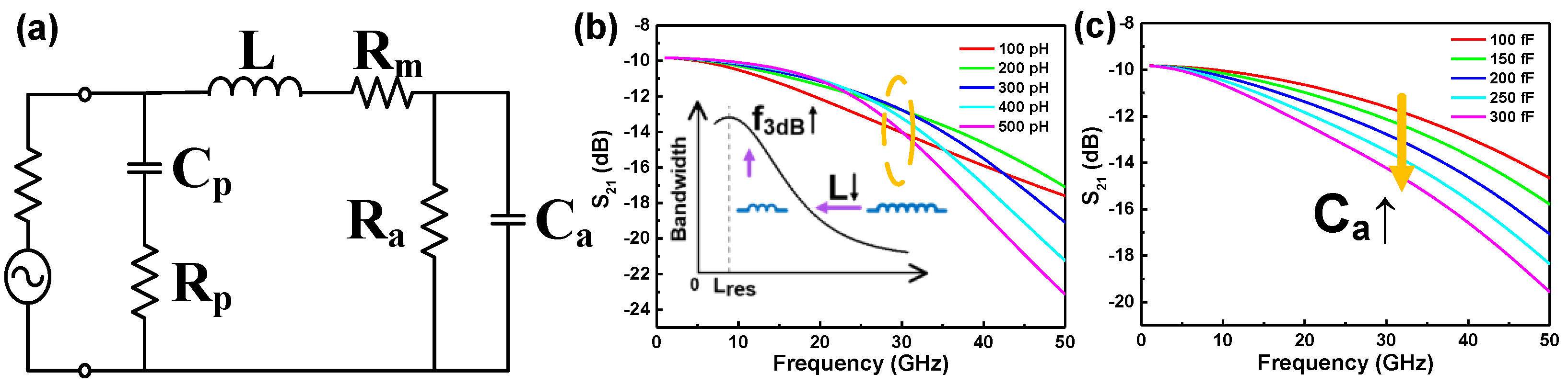
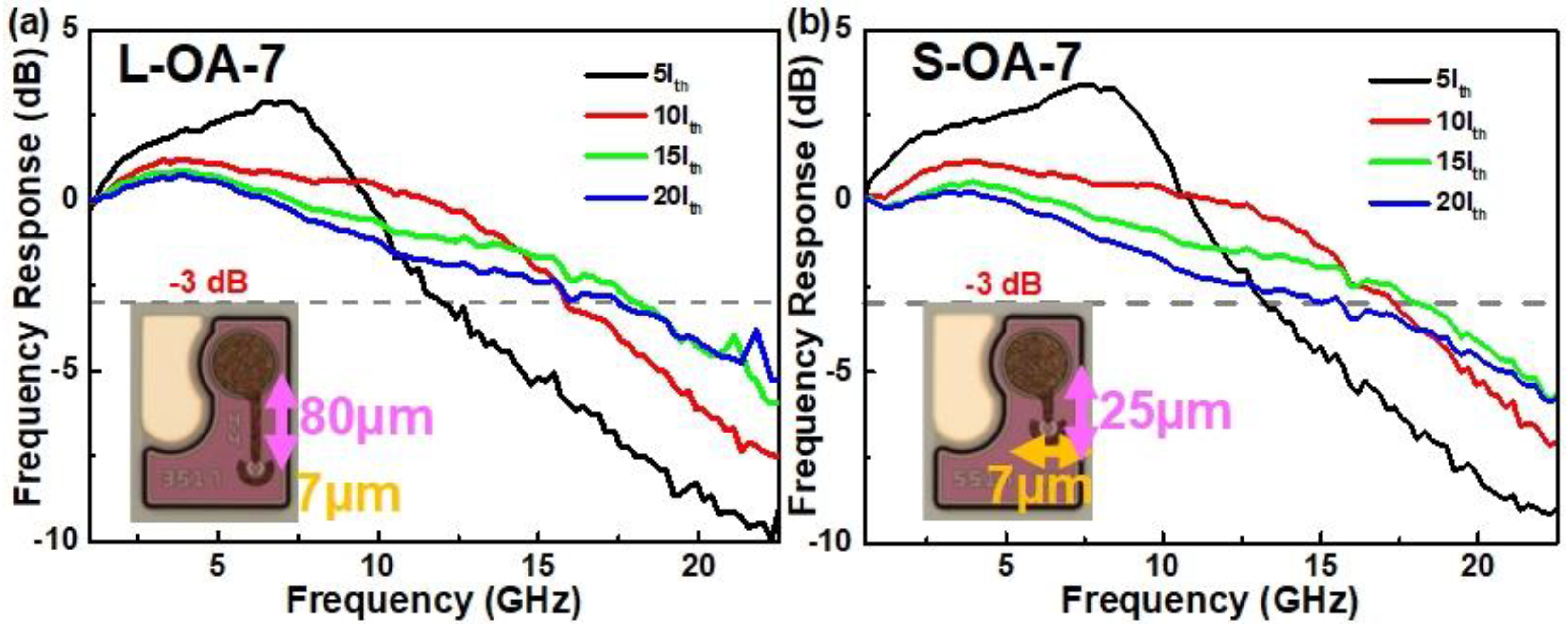
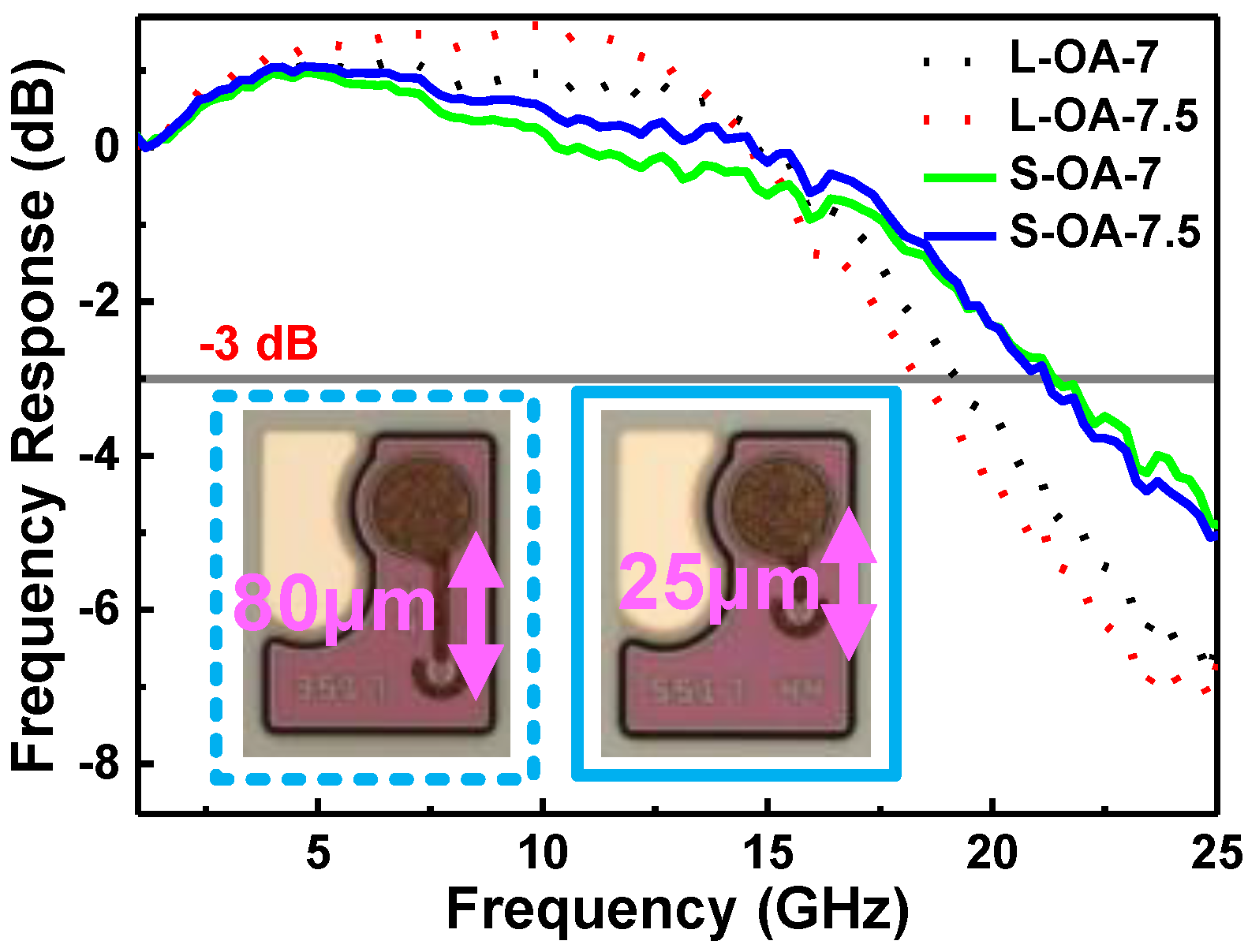
3.2. Modulation Responses of the MM-VCSELs

To analyze the small-signal modulation response, the equivalent circuits of the MM-VCSELs with different designs are constructed to include the intrinsic and extrinsic responses. The equivalent circuit of the MM-VCSEL is described in Figure 5a. L indicates the inductance of the microstrip transmission line between contacting pad and VCSEL electrode. Rm is the resistance across the DBR layer of the MM-VCSEL. Cp is the frequency-dependent pad capacitance between the metal contact and the bottom mirror stack layer. Rp is the resistance produced by the frequency-dependent dielectric losses in the benzocyclobutene layer. Ra represents that the serial resistance in the active region includes the current path limited by the oxide aperture. Ca is the total capacitance including the p-n junction, the oxide aperture, and the intrinsic layer capacitance [32,37]. By using the commercial software (Keysight, Advanced Design System, Santa Rosa, CA, USA) to simulate, the simulated frequency responses based on the equivalent circuit of MM-VCSEL by varying the effective inductance are demonstrated in Figure 5b. The widest 3 dB bandwidth will be simulated by tuning the effective inductance, as shown in Figure 5b. The impedance between the extrinsic inductance of the transmission microstrip and the capacitance of the intrinsic active region can be matched to reduce the imaginary impedance. This phenomenon significantly mitigates the power loss to achieve the maximal bandwidth. From the inset of Figure 5b, the inductance value of this MM-VCSEL locates at the right side of the maximal 3-dB bandwidth. In addition, the simulated frequency responses can be varied by changing the Ca, as shown in Figure 5c. In Figure 5c, the 3-dB bandwidth of the MM-VCSEL shrinks with increasing capacitance. The smaller oxide aperture design has less capacitance to achieve a more broadened modulation bandwidth. Furthermore, the smaller oxide aperture size enhances the carrier density to provide a larger relaxation oscillation frequency. These phenomena can effectively improve the modulation capacity of the MM-VCSEL.
The frequency responses of the MM-VCSELs with the designs of L-OA-7 and S-OA-7 are displayed in Figure 6a,b, respectively. The sinusoidal wave for modulating the MM-VCSEL was generated from a radio-frequency (RF) synthesizer (Agilent, E4433B, Santa Clara, CA, USA) with a scanning range from 250 kHz to 22 GHz. After directly modulating the MM-VCSEL, the device output was received by a PD. Then, the converted signal was analyzed by an electrical spectrum analyzer (ESA, Agilent, 8565E). In addition, the LabVIEW program was used to control the RF synthesizer and ESA. Increasing the bias current upshifts the resonance frequency to the high frequency. This also enhances the damping effect to induce a flatten and broadened modulation response. The 3-dB bandwidths of the MM-VCSELs with designs of L-OA-7 and S-OA-7 under the 15Ith operation are, respectively, measured as 18.0 and 19.2 GHz. Further increasing the bias current to 20Ith suppresses the 3-dB modulation bandwidths to 17.34 and 15.7 GHz for the MM-VCSEL with designs of L-OA-7 and S-OA-7, respectively, because of the overdamped effect in VCSEL under the high-current operation. From the abovementioned results, the critically damped point is located around 15Ith to provide a reference for the bias optimization in the high-speed transmission test. Table 3 summarizes the 3-dB modulation bandwidths of the MM-VCSELs with four designs under the 15Ith operation. The MM-VCSELs with four designs of L-OA-7/L-OA-7.5/S-OA-7/S-OA-7.5 reveal their respective 3-dB bandwidths of 18.75/18.51/19.21/18.98 GHz under the 15Ith operation. Regardless of the MM-VCSELs with L- or S-type designs, the difference of 3-dB bandwidth for the MM-VCSELs with different oxide apertures is about 0.2 GHz. Furthermore, different transmission lines of the MM-VCSEL induce the additional equivalent inductance and serial resistance to generate the 0.5-GHz change of the modulation bandwidth. Therefore, the MM-VCSEL with the design of S-OA-7 is the best design among all the devices.
For the abovementioned results, the transmission microstrip connected between the VCSEL and metal padding can be used to sufficiently optimize impedance matching and improve the 3-dB modulation bandwidth because the transmission microstrip can be regarded as the series resistance and inductance to detune the impedance via adjusting its length. Furthermore, the 3-dB modulation bandwidth of the MM-VCSEL can be enhanced by changing the oxide aperture to vary the capacitance in the active region matching the series inductance.

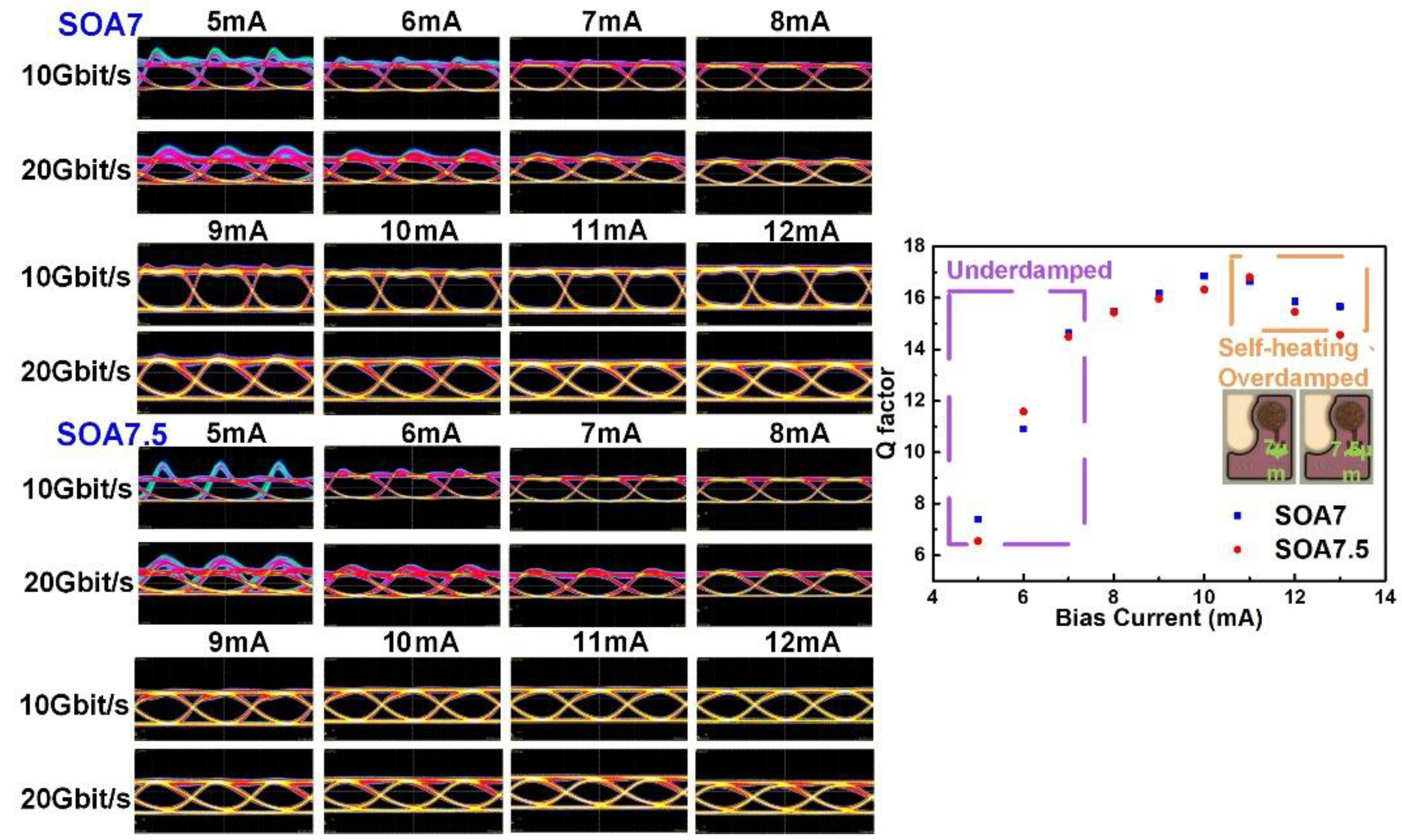
3.3. Bias Current Optimization for High-Speed Transmission

The D factor indicates the modulation efficiency of an intrinsic laser to represent the capability to reach the high relaxation oscillation frequency at a low bias current. The D factor can be expressed as [38]:
D = v g g / N η i 4 π 2 q V p ,
where νg denotes the group velocity of light; ∂g/∂N the differential gain; Vp the effective mode volume; ηi the current injection efficiency as the fraction of the terminal current generating the carrier in the active layer. A drastic phase change can be induced when the largest resonance amplitude occurs. The damping rapidly attenuates the oscillation in the laser to result in a flattened modulation response. The bias current controls the carrier and photon densities and the relaxation oscillation frequency. The relaxation oscillation frequency can be described as [38]:
f R = D I I t h ,
where fR denoting the relaxation oscillation frequency is proportional to the root of bias current when bias current is much greater than the threshold current. Furthermore, the damping factor and relaxation oscillation frequency will simultaneously limit the modulation bandwidth of the VCSEL. In addition to high relaxation oscillation frequency, the low damping factor is essential for high-speed modulation. The K factor can be expressed as the following formula [38],
K = 4 π 2 τ p + ε v g g / N ,
where τp denotes the photon lifetime; ε the gain compression factor. In addition, the damping factor can also be represented as [38]:
γ = K f R 2 + γ 0 = K f R 2 + 1 τ Δ N + Γ R s p N p ,
where γ denotes the damping factor approximately proportional to the square of the relaxation oscillation frequency; γ the damping factor offset; Γ the optical confinement factor; Rsp the rate per unit volume of spontaneous emission into the lasing mode; τΔN the differential carrier lifetime; Np the photon density. The damping factor offset usually appears only near the threshold current. When VCSEL operates under the high-current region, the excessive damping induced by the gain compression effect will slow down the response of the VCSEL. Figure 7 exhibits the eye diagrams and Q-factor of the MM-VCSEL with designs of S-OA-7 and S-OA-7.5 under different bias currents and the same input amplitude for 10-Gbit/s and 20-Gbit/s NRZ-OOK transmission. The overshoot effect is correlated to the operating bias current and the modulated input amplitude. The overshoot effect is related to the bias condition and the modulated input amplitude. To optimize the operating condition, the bias current of MM-VCSEL is optimized by the Q factor from the eye diagram to compare the damping level [39]. The overshoot induced by underdamping dominates the Q factor at low bias. Under the high-bias condition, the decreased slope efficiency by the self-heating effect and the compressed 3-dB bandwidth by the overdamping effect will attenuate the amplitude of the signal to limit the Q factor. The overshoot in the eye diagram is avoided at the critically damping point by detuning the bias current.
In Figure 7, the damping effect has almost the same influence on the MM-VCSELs with two designs from the optimization curve because of the tiny design difference between these two devices. Therefore, the optimized bias currents are located at 16.66Ith and 16.92Ith for the MM-VCSELs with two designs of S-OA-7 and S-OA-7.5, respectively. For 10 Gbit/s transmission, the lower damping decided by the lower D factor for the MM-VCSEL with the design of S-OA-7.5 causes the more significant overshoot in the eye diagram. In addition, the low damping also induces a long oscillation to degrade the transmission performance. With increasing bias current below 8 mA, the relaxation oscillation frequency, damping factor, and modulation bandwidth increase to suppress the duration of oscillation and overshoot. Because the pulsewidth for each bit is shortened by half for the 20 Gbit/s transmissions, the overshoot duration is severely deformed in the eye diagram and interferes with the next bit. Therefore, it is necessary to overcome the overshoot in high-speed transmission.
Figure 8a shows the horizontal BER bathtubs of the 40-Gbit/s NRZ-OOK data carried by the MM-VCSEL with the design of S-OA-7 under different bias currents. From Figure 8a, the lowest root-mean-square jitter value can be obtained as 1.70 ps under a BER of 10−12 when the MM-VCSEL is operated at 10 mA. The underdamping effect still exists at 8 mA to degrade the root-mean-square jitter (RMSJ) to 1.93 ps by the excessive data history-dependent timing jitter. By further enlarging the bias current to 12 mA, the RMSJ also decays to 1.84 ps because of the rise time limited by the reduced 3-dB modulation bandwidth. The vertical BER bathtub of the 40-Gbit/s NRZ-OOK data carried by the MM-VCSEL with the design of S-OA-7 under different bias currents are displayed in Figure 8b.
The limitation for overshoot is more critical in high-speed transmission to make the BER value under the 8-mA operation higher than those under other current operations. Increasing the bias current to 10 mA suppresses the overshoot effect to improve the BER. The BER becomes higher when the MM-VCSEL is operated at 12 mA because of the decreased slope efficiency and 3-dB bandwidth. In the inset of Figure 8b, the eye diagrams under different bias operations have a similar phenomenon to confirm the abovementioned results. Furthermore, the modulation frequency and Q factor of the MM-VCSELs with four designs are further optimized via the bias current optimization.
Figure 9 shows the frequency responses of the MM-VCSELs with four designs operated at their optimized Q factor conditions. The optimized 3-dB bandwidths of the MM-VCSELs with four designs of L-OA-7/L-OA-7.5/S-OA-7/S-OA-7.5 are respectively obtained as 19.2/18.2/21.3/21.1 GHz under their corresponding optimized bias currents of 8/9/10/11 mA, as summarized as Table 4. The reflection coefficient of the MM-VCSEL with the L-type design is larger than that of the MM-VCSEL with the S-type design. That is because the extra transmission microstrip length induces impedance mismatching. After the tradeoff between the modulation slope efficiency and the resonance frequency, the high signal reflection for the MM-VCSEL with the L-type design needs the appropriate bias to overcome the insufficient output signal amplitude. To avoid reducing slope efficiency by self-heating, the optimized bias current for the MM-VCSEL with the L-type design is lower than that for the MM-VCSEL with the S-type design. Besides, the optimized bias current for the MM-VCSEL with the 7.5-µm-oxide-aperture designs is higher than that for the MM-VCSEL with the 7-µm-oxide-aperture designs. This is because the devices with larger oxide aperture have lower carrier density to require a higher bias current for achieving the critically damping operation.

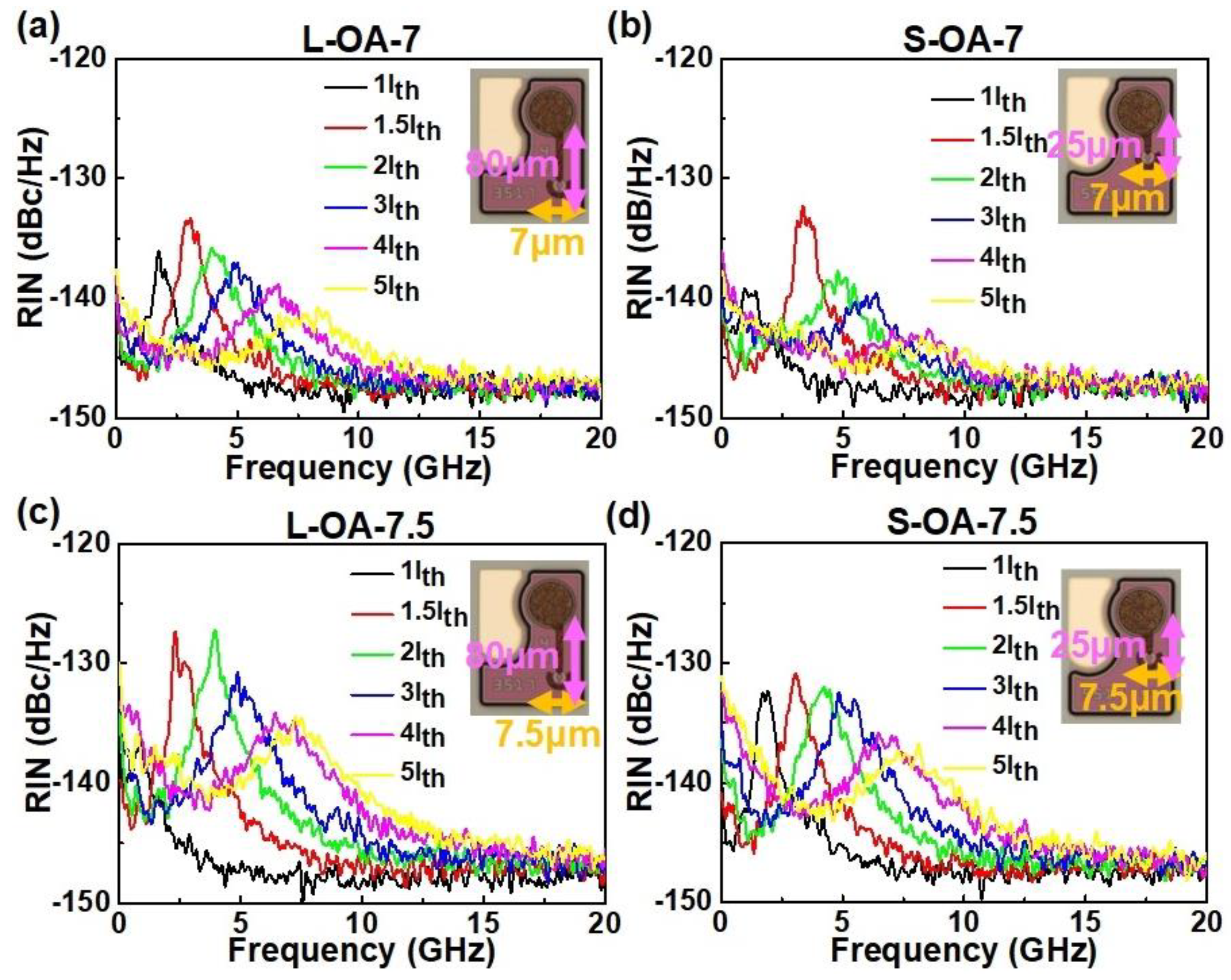
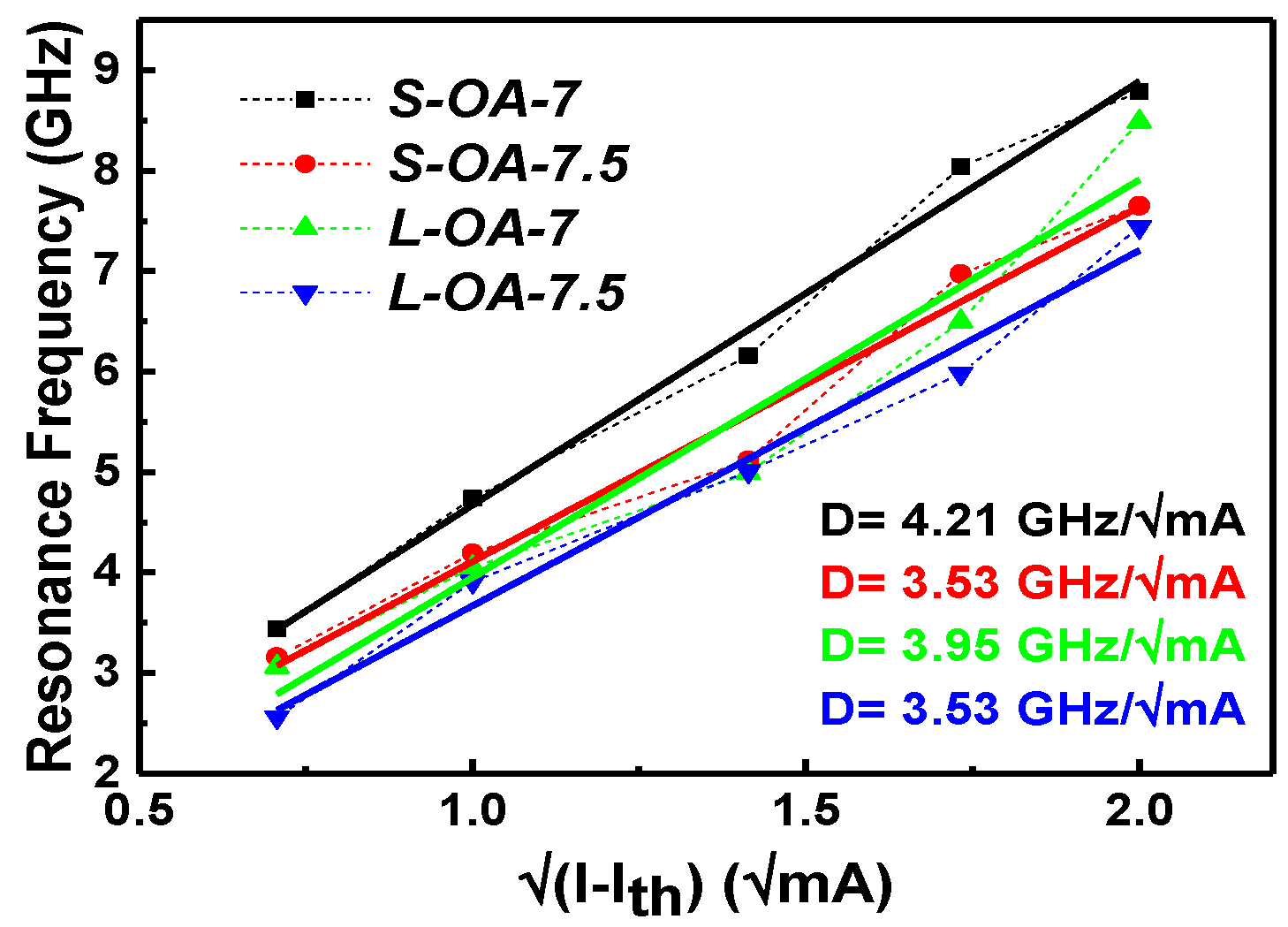
3.4. RIN and MPN of the MM-VCSELs with Different Designs

Figure 10a–d exhibit the relative intensity noise (RIN) spectra ranging from 0 to 20 GHz for the MM-VCSELs with different designs of L-OA-7/S-OA-7/L-OA-7.5/S-OA-7.5. Because the primary source of RIN is originated from the spontaneous emission of the MM-VCSEL, the operation current approaches the threshold current to increase the RIN value [40]. In addition, the resonance frequency of the MM-VCSEL upshifts toward the high frequency by increasing the bias current. The noise peak around the resonance frequency gradually immerses into shot noise because of the damping enhancement. From Figure 10a–d, the MM-VCSEL with the smaller oxide aperture has a higher photon density to induce the faster frequency shift. Because of the larger optical volume and lower photon density, the higher RIN values are observed for the MM-VCSELs with the larger oxide aperture from the experimental results. At the low bias current, the lower damping factor and lower resonance frequency induced by the lower photon density for the MM-VCSEL with the designs of L-OA-7.5/S-OA-7.5 increase the RIN value [41,42], as confirmed by Figure 7.
The resonance frequency for the MM-VCSELs with four designs under different bias currents is shown in Figure 11. The D factor can be obtained from the slope to indicate the modulation efficiency of an intrinsic laser. The MM-VCSELs with the design of L-OA-7/L-OA-7.5/S-OA-7/S-OA-7.5, respectively, obtain their D factors of 3.95/3.53/4.21/3.53 GHz/mA0.5. Because of the higher photon density in the MM-VCSEL with the smaller oxide aperture design, the D factor for the MM-VCSEL with the OA-7 design is larger than for the MM-VCSEL with the OA-7.5 design. The mode partition noise (MPN) is induced by an interaction between the carrier distribution and mode intensity. Transverse modes will compete in inhomogeneous carrier distribution to affect the dynamic response in VCSELs.
At a high mode intensity point, the stimulated recombination depletes the local carriers and produces a hole in the carrier distribution. This phenomenon is called the spatial hole burning effect (SHB) [43,44,45,46,47]. The lacking carriers in the hole compress the current mode and then enhance the other modes. This effect is also called mode switching. The VCSEL usually operates at the high-bias operation for sufficient frequency response under the high-speed transmission. The resonance noise peak immerses into the shot noise to only slightly affect the transmission performance. The remaining MPN mainly limits the high-speed transmission performance to induce a worse root-mean-square noise (RMSN) in two levels of the OOK modulation. To analyze MPN appearing from the RIN spectrum in the low-frequency region, the zoomed-in RIN spectra ranging from 10 to 100 MHz for the MM-VCSELs with different designs of L-OA-7/S-OA-7/L-OA-7.5/S-OA-7.5 are shown in Figure 12a–d. The MPN occurs in the low-frequency region with mode-selective coupling. The high RIN value also appears in the low-frequency region from 10 to 100 MHz with poor alignment when the relaxation oscillation frequency already upshifts to the high-frequency region. The less mode competition happens in the smaller oxide aperture because of the less spatial overlap by transverse modes [41,48,49,50]. The overlap of the transverse mode in the MM-VCSEL with the large oxide aperture is more prominent with less current confinement, which indicates the more severe mode competition. Therefore, the MM-VCSELs with the larger oxide aperture have higher RIN in the low-frequency region because of the stronger mode competition.
Table 5 summarizes the average RIN values ranging from 10 to 100 MHz at the bias currents of 1/5/10Ith for the MM-VCSELs with four designs. By increasing the bias current, the greater MPN is caused by locally higher stimulated recombination [38]. The discrepancy of RIN for the MM-VCSELs with four designs is considered to analyze the MPN. The RINs of the MM-VCSELs with designs of L-OA-7/L-OA-7.5/S-OA-7/S-OA-7.5 are, respectively, increased to 6.2/11.4/4.1/9.1 dBc/Hz as the bias current enlarges to 10Ith. The abovementioned results verify that the mode competition will become more severe with the expansion of the oxide aperture size.

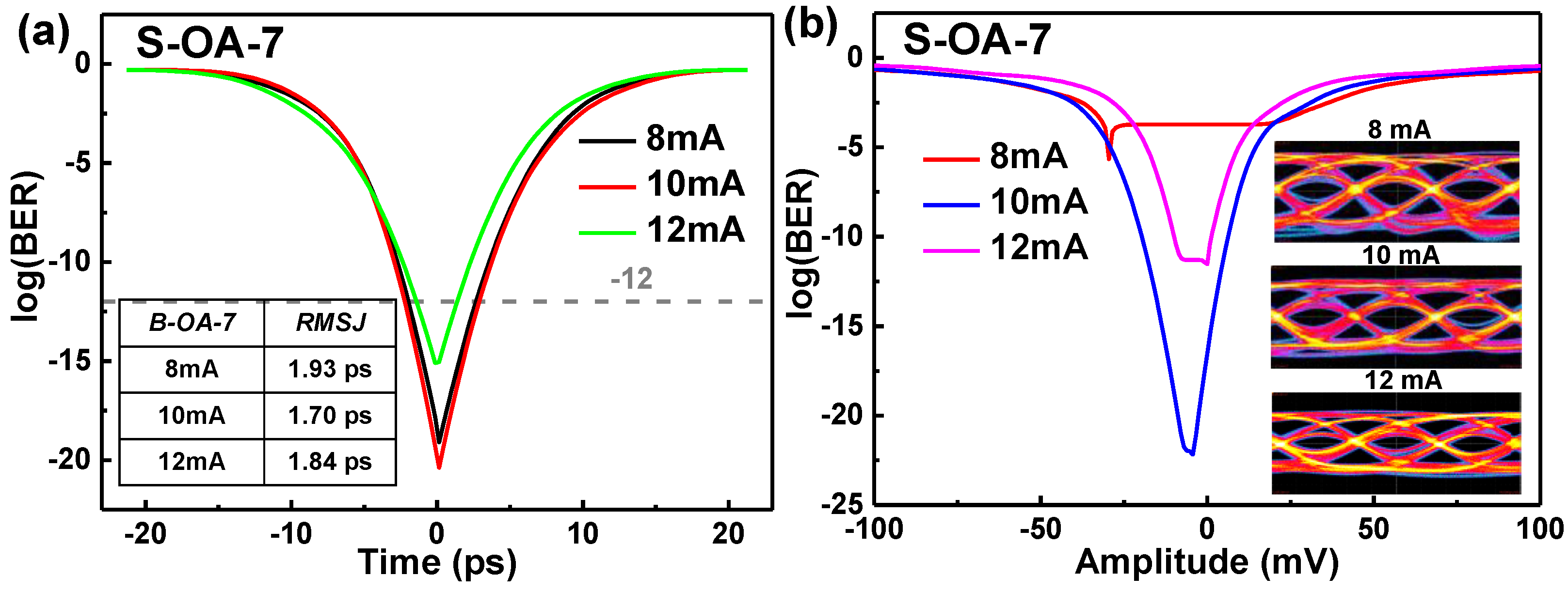
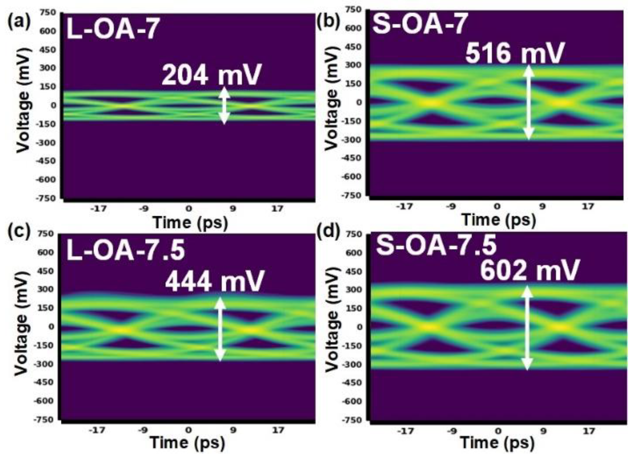
3.5. Transmission Performances in the MM-VCSELs with Four Designs

The eye diagrams of the 40 Gbit/s NRZ-OOK data carried by the MM-VCSELs with four designs of L-OA-7/S-OA-7/L-OA-7.5/S-OA-7.5 under their optimized bias current and the same signal amplitude are shown in Figure 13a–d. After receiving the photodetector with a conversion gain of 65 V/W, the signal amplitudes of the modulated outputs are respectively obtained as 204/444/516/602 mV for the MM-VCSELs with four designs of L-OA-7/L-OA-7.5/S-OA-7/S-OA-7.5 with an electrical input signal amplitude of 800 mV. Because the MM-VCSEL with the design of L-OA-7.5 exhibits nearly twice larger slope efficiency and lower reflection coefficient than that with the design of L-OA-7, the eye diagram amplitude of the MM-VCSEL with the design of L-OA-7.5 is larger than that of the MM-VCSEL with the design of L-OA-7, as shown in Figure 13a,c. In Figure 13b,d, the same trend is observed for the MM-VCSEL with the S-type design.
The performances of the NRZ-OOK and PAM-4 transmissions carried by the MM-VCSEL with the design of S-OA-7 are shown in Figure 14a,b. By using the pre-emphasis technology to pre-distort the waveform, the data rate of the NRZ-OOK transmission can be achieved to 50 Gbit/s to pass the telecom criterion. The amplitude and RMSN of the received data can be measured as 61 and 4.9 mV, respectively. Furthermore, the 42 GBaud PAM-4 data transmission is demonstrated with a corresponding data rate of 84 Gbit/s, an amplitude of 80 mV, and an RMSN of 6.3 mV to pass the KP4 criterion when the MM-VCSEL with the design of S-OA-7 is used as the optical carrier. Figure 14c,d exhibit the MM-VCSEL with the design of S-OA-7.5 carrying the NRZ-OOK and PAM-4 data to compare the high-speed capability with the MM-VCSEL with the design of S-OA-7. The MM-VCSEL with the design of S-OA-7 can reach the 48-Gbit/s NRZ-OOK transmission with an amplitude of 74 mV and an RMSN of 5.8 mV. In addition, the 41 GBaud PAM-4 data transmission with a corresponding data rate of 82 Gbit/s can be demonstrated with an amplitude of 95 mV and an RMSN of 8.5 mV. The maximal data rates of the NRZ-OOK and PAM-4 data carried by the MM-VCSELs with four designs are summarized in Table 6. The MM-VCSEL with the design of L-OA-7 possesses the worst transmission performance among the four devices because of its most significant reflection coefficient, insufficient bandwidth, and slope efficiency. The MM-VCSEL with the design of L-OA-7.5 exhibits its best slope efficiency to achieve better performance than that with the design of L-OA-7. The 3-dB bandwidth of the MM-VCSEL with the S-type design is broader than that with the L-type design to demonstrate better transmission performance. The MM-VCSEL with the design of S-OA-7.5 possesses a large oxide aperture to enhance the MPN. This enhanced MPN can degrade the SNR to suppress the transmission rate, even though this device has a larger modulated output amplitude because of its smallest reflection coefficient and better slope efficiency. Therefore, the MM-VCSEL with the design of S-OA-7 is the most suitable device to achieve the highest speed transmission capability in this work after considering the reflection coefficient, the slope efficiency, RMS spectral width, 3-dB bandwidth, D factor, and RIN noise.

4. Conclusions

In this work, the extrinsic and intrinsic responses of the MM-VCSELs induced by the impact of transmission microstrip length and oxide aperture size are discussed for achieving the 50 Gbit/s communication. The equivalent circuit model of the MM-VCSEL is used to consider both extrinsic inductance and intrinsic capacitance designs. Tuning the transmission microstrip length between the metal padding and the intrinsic VCSEL to match with the VCSEL design is proposed to achieve a low reflection coefficient. The inductance in transmission microstrip in the series connection with the capacitance in the active region also affects the 3-dB modulation bandwidth of the MM-VCSEL. The design of the oxide aperture size for the MM-VCSEL adjusts the slope efficiency and the capacitance in the active region. In this work, shortening the transmission microstrip length of 55 mm reduces the inductance in the equivalent circuit of the MM-VCSEL to improve the 3-dB modulation bandwidth to 18.98 GHz under 15-Ith operation. On the other hand, suppressing the oxide aperture size by 0.5 mm reduces the capacitance of the active region to further enhance the 3-dB modulation bandwidth to 19.21 GHz under the same operation. Furthermore, the MM-VCSEL with the small aperture design has a more significant D factor of 4.21 GHz/mA0.5 to represent the high modulation efficiency. For the MM-VCSELs with four designs, the device with a diameter of 7 µm oxide aperture and a length of 25 µm transmission microstrip exhibits a low reflection coefficient of 0.2, a high slope efficiency of 0.27–0.36 W/A, and a high 3-dB modulation bandwidth of 19.2 GHz. A tradeoff between the relaxation oscillation frequency and the modulated slope efficiency is also discussed. The high resonance frequency supports a broadened 3-dB modulation bandwidth for high-speed transmission. For the cases of insufficient modulated output amplitude, selecting a high slope efficiency produces a larger signal amplitude to enhance SNR. As the bias current increases, the resonance-frequency noise upshifts toward the high-frequency region and immerses into shot noise with a slight RIN value of −142.2 dBc/Hz. The MPN in the low-frequency region induced by the mode overlap directly limits the SNR during transmission. The lower photon density and severe transverse mode overlap in larger oxide aperture design lead to the large RIN and MPN. Considering the impact of modulated slope efficiency and RIN/MPN for the NRZ-OOK and PAM-4 transmission performances, the best design of the MM-VCSELs in this work can be found. Optimizing the operating bias current by the Q factor to consider the damping effect in the eye diagram plays a key role in the high-speed transmission. After the optimized process, the directly modulated 850-nm MM-VCSEL with 25-µm-transmission-microstrip and 7-µm-oxide-aperture is suitable to demonstrate the high-speed application. After pre-emphasis techniques, the 50 Gbit/s NRZ-OOK transmission under the telecom criterion and 42 GBaud PAM-4 format under the KP4-FEC criterion can be achieved. This MM-VCSEL with the optimized transmission microstrip length and oxide aperture size can be verified for future data-center applications.

Author Contributions

Conceptualization, G.-R.L. and C.J.C.-H.; Methodology, J.W., P.Q., C.-C.S. and C.J.C.-H.; Validation, J.-H.W. and G.-R.L.; Formal analysis, J.-H.W. and W.-C.L.; Data curation, J.-H.W.; Writing—original draft preparation, J.-H.W.; Writing—review and editing, C.-H.C., G.-R.L. and C.J.C.-H.; Supervision, G.-R.L. and C.J.C.-H.; Project administration, G.-R.L. and C.J.C.-H.; Funding acquisition, G.-R.L. All authors have read and agreed to the published version of the manuscript.

Funding

This work is supported by the Ministry of Science and Technology, Taiwan, under Grants MOST 109-2221-E-002-184-MY3, MOST 110-2221-E-002-100-MY3, MOST 110-2124-M-A49-003-, and MOST 110-2224-E-992-001-.

Institutional Review Board Statement

Not applicable.

Informed Consent Statement

Not applicable.

Data Availability Statement

The data presented in this study are available on request from the corresponding author.

Conflicts of Interest

The authors declare no conflict of interest.

References

  1. Cisco Annual Internet Report (2018–2023) White Paper. Available online: http://www.cisco.com/c/en/us/solutions/collateral/executive-perspectives/annual-internet-report/white-paper-c11-741490.html (accessed on 9 March 2020).
  2. Mutig, A. High Speed VCSELs for Optical Interconnects. Ph.D. Thesis, Technische Universität Berlin, Berlin, Germany, 2010. [Google Scholar]
  3. Huang, C.-Y.; Wang, H.-Y.; Wu, C.-H.; Cheng, C.-H.; Tsai, C.-T.; Wu, C.-H.; Feng, M.; Lin, G.-R. Comparison of high-speed PAM4 and QAM-OFDM data transmission using single-mode VCSEL in OM5 and OM4 MMF links. IEEE J. Sel. Top. Quantum Electron. 2020, 26, 1500210. [Google Scholar] [CrossRef]
  4. Kao, H.-Y.; Tsai, C.-T.; Chi, Y.-C.; Peng, C.-Y.; Leong, S.-F.; Wang, H.-Y.; Cheng, C.-H.; Wu, W.-L.; Kuo, H.-C.; Cheng, W.-H.; et al. Long-term thermal stability of single-mode VCSEL under 96-Gbit/s OFDM transmission. IEEE J. Sel. Top. Quantum Electron. 2019, 25, 1500609. [Google Scholar] [CrossRef]
  5. Li, M.; Chen, X.; Li, K.; Hurley, J.E.; Stone, J. Optical fiber for 1310 nm single-mode and 850 nm few-mode transmission. Proc. SPIE 2019, 10945, 1094503. [Google Scholar]
  6. Wang, H.L.; Qiu, J.; Yu, X.; Fu, W.; Feng, M. The Modal Effect of VCSELs on Transmitting Data Rate Over Distance in OM4 Fiber. IEEE J. Quantum Electron. 2020, 56, 8000106. [Google Scholar] [CrossRef]
  7. Westbergh, P.; Gustavsson, J.S.; Haglund, Å.; Larsson, A.; Hopfer, F.; Fiol, G.; Bimberg, D.; Joel, A. 32 Gbit/s multimode fibre transmission using high-speed, low current density 850 nm VCSEL. Electron. Lett. 2009, 45, 366–368. [Google Scholar] [CrossRef]
  8. Blokhin, S.A.; Lott, J.A.; Mutig, A.; Fiol, G.; Ledentsov, N.N.; Maximov, M.V.; Nadtochiy, A.M.; Shchukin, V.A.; Bimberg, D. Oxide-confined 850 nm VCSELs operating at bit rates up to 40 Gbit/s. Electron. Lett. 2009, 45, 501–503. [Google Scholar] [CrossRef]
  9. Lin, Y.-H.; Tsai, C.-T.; Wu, W.-L.; Cheng, C.-H.; Choquette, K.D.; Lin, G.-R. Photonic Crystal Structured Multimode VCSELs Enabling 92-Gbit/s QAM-OFDM Transmission. J. Lightwave Technol. 2021, 39, 4331–4340. [Google Scholar] [CrossRef]
  10. Huang, C.-Y.; Tsai, C.-T.; Weng, J.-H.; Cheng, C.-H.; Wang, H.-Y.; Wu, C.-H.; Feng, M.; Lin, G.-R. Temperature and Noise Dependence of Tri-Mode VCSEL Carried 120-Gbit/s QAM-OFDM Data in Back-to-Back and OM5-MMF Links. J. Lightwave Technol. 2020, 38, 6746–6758. [Google Scholar] [CrossRef]
  11. 800G Specification-Ethernet Technology Consortium. Available online: https://ethernettechnologyconsortium.org/wp-content/uploads/2020/03/800G-Specification_r1.0.pdf (accessed on 10 March 2020).
  12. Hansing, C.C.; Deng, H.; Huffaker, D.L.; Deppe, D.G. Low-threshold continuous-wave surface emitting lasers with etched-void confinement. IEEE Photon. Technol. Lett. 1994, 6, 320–322. [Google Scholar] [CrossRef]
  13. Huffaker, D.L.; Deppe, D.G.; Kumar, K.; Rogers, T.J. Native-oxide defined ring contact for low-threshold vertical-cavity lasers. Appl. Phys. Lett. 1994, 65, 97–99. [Google Scholar] [CrossRef]
  14. Hayashi, Y.; Mukaihara, T.; Hatori, N.; Ohnoki, N.; Matsutani, A.; Koyama, F.; Iga, K. Record low-threshold index-guided InGaAs/GaAlAs vertical-cavity surface-emitting laser with a native oxide confinement structure. Electron. Lett. 1995, 31, 560–561. [Google Scholar] [CrossRef]
  15. Chow, W.W.; Choquette, K.D.; Crawford, M.H.; Lear, K.L.; Hadley, G.R. Design, fabrication, and performance of infrared and visible vertical-cavity surface emitting lasers. IEEE J. Quantum Electron. 1997, 33, 1810–1823. [Google Scholar] [CrossRef] [Green Version]
  16. Feng, M.; Wu, C.H.; Holonyak, N. Oxide-confined VCSELs for high-speed optical interconnects. IEEE J. Quantum Electron. 2018, 54, 2400115. [Google Scholar] [CrossRef]
  17. Suemune, I. Theoretical study of differential gain in strained quantum well structures. IEEE J. Quantum Electron. 1991, 27, 1149–1159. [Google Scholar] [CrossRef]
  18. Healy, S.B.; O’Reilly, E.P.; Gustavsson, J.S.; Westbergh, P.; Haglund, Å.; Larsson, A.; Joel, A. Active region design for high speed 850 nm VCSELs. IEEE J. Quantum Electron. 2010, 46, 506–512. [Google Scholar] [CrossRef]
  19. Lau, K.Y.; Yariv, A. Ultra-high speed semiconductor lasers. IEEE J. Quantum Electron. 1985, 21, 121–138. [Google Scholar]
  20. Ou, Y.; Gustavsson, J.S.; Westbergh, P.; Haglund, A.; Larsson, A.; Joel, A. Impedance characteristcs and parasitic speed limitations of high-speed 850-nm VCSELs. IEEE Photon. Technol. Lett. 2009, 21, 1840–1842. [Google Scholar] [CrossRef]
  21. Cheng, C.-H.; Shen, C.-C.; Kao, H.-Y.; Hsieh, D.-H.; Wang, H.-Y.; Yeh, Y.-W.; Lu, Y.-T.; Huang Chen, S.-W.; Tsai, C.-T.; Chi, Y.-C.; et al. 850/940-nm VCSEL for optical communication and 3D sensing. Opto-Electron. Adv. 2018, 1, 180005. [Google Scholar] [CrossRef]
  22. Chang, Y.-C.; Wang, C.; Johansson, L.; Coldren, L. High-efficiency, high-speed VCSELs with deep oxidation layers. Electron. Lett. 2006, 42, 1281–1282. [Google Scholar] [CrossRef] [Green Version]
  23. Westbergh, P.; Gustavsson, J.S.; Haglund, Å.; Sköld, M.; Joel, A.; Larsson, A. High speed low current density 850 nm VCSELs. IEEE J. Sel. Topics Quantum Electron. 2009, 15, 694–703. [Google Scholar] [CrossRef]
  24. Westberge, P.; Safaisini, R.; Haglund, E.; Gustavsson, J.S.; Larsson, A.; Geen, M.; Lawrence, R.; Joel, A. High-speed oxide confined 850-nm VCSELs operating error-free at 40 Gb/s up to 85 °C. IEEE Photon. Technol. Lett. 2013, 25, 768–771. [Google Scholar] [CrossRef]
  25. Kao, H.-Y.; Tsai, C.-T.; Leong, S.-F.; Peng, C.-Y.; Chi, Y.-C.; Wang, H.-Y.; Kuo, H.-C.; Wu, C.-H.; Cheng, W.-H.; Lin, G.-R. Single-mode VCSEL for pre-emphasis PAM-4 transmission up to 64 Gbit/s over 100-300 m in OM4 MMF. Photonics Res. 2019, 6, 666–673. [Google Scholar] [CrossRef]
  26. Haglund, E.; Haglund, Å.; Gustavsson, J.S.; Kögel, B.; Westbergh, P.; Larsson, A. Reducing the spectral width of high speed oxide confined VCSELs using an integrated mode filter. Proc. SPIE 2012, 8276, 82760L. [Google Scholar]
  27. Aoki, T.; Kubota, R.; Yoshimoto, S.; Yanagisawa, M.; Ishizuka, T.; Shoji, H. High-speed VCSEL arrays for 400 Gbit/s data center interconnects. SEI Tech. Rev. 2020, 90, 71–75. [Google Scholar]
  28. Ralph, S.E.; Lavrencik, J. VCSEL modal dynamics and implications for 100Gbps links. Proc. SPIE 2017, 10122, 101220E. [Google Scholar]
  29. Ralph, S.E.; Lavrencik, J.; Melgar, A. VCSELs and 100G. Proc. SPIE 2019, 10938, 1093803. [Google Scholar]
  30. Melgar, A.; Thomas, V.A.; Ralph, S.E. Multi-Objective Laser Rate Equation Based Parameter Extraction Using VCSEL Small Signal Response and RIN Spectra. J. Lightwave Technol. 2020, 38, 6437–6445. [Google Scholar] [CrossRef]
  31. Lavrencik, J.; Gustavsson, J.S.; Haglund, E.; Larsson, A.; Ralph, S.E. Optimum VCSEL apertures for high-speed multimode fiber links. In Proceedings of the 2018 Optical Fiber Communications Conference and Exposition (OFC), San Diego, CA, USA, 11–15 March 2018. [Google Scholar]
  32. Hamad, W.; Sanayeh, M.B.; Hamad, M.M.; Hofmann, W.H.E. Impedance characteristics and chip-parasitics extraction of high-performance VCSELs. IEEE J. Quantum. Electron. 2020, 56, 2400111. [Google Scholar] [CrossRef]
  33. Szczerba, K.; Lengyel, T.; Karlsson, M.; Andrekson, P.A.; Larsson, A. 94 Gbps 4-PAM using an 850 nm VCSEL, pre-emphasis and receiver equalization. IEEE Photon. Technol. Lett. 2016, 28, 2519–2521. [Google Scholar] [CrossRef]
  34. 80SJARB and 80SJNB Jitter, Noise, and BER Analysis; Tektronix Inc.: Beaverton, OR, USA, 2016.
  35. Peng, C.-Y.; Tsao, K.; Cheng, H.-T.; Feng, M.; Wu, C.-H. Investigation of the current influence on near-field and far-field beam patterns for an oxide-confined vertical-cavity surface-emitting laser. Opt. Express 2020, 28, 30748–30759. [Google Scholar] [CrossRef]
  36. Arafin, S.; Bachmann, A.; Amann, M.-C. Transverse-mode characteristics of GaSb-Based VCSELs with buried-tunnel junctions. IEEE J. Sel. Top. Quantum Electron. 2011, 17, 1576–1583. [Google Scholar] [CrossRef]
  37. Tatum, J.; Smith, D.; Guenter, J.; Johnson, R. High-speed characteristics of VCSELs. Proc. SPIE 1997, 3004, 151–159. [Google Scholar]
  38. Mutig, A.; Bimberg, D. Progress on high-speed 980 nm VCSELs for short-reach optical interconnects. Adv. Opt. Technol. 2011, 2011, 290508. [Google Scholar] [CrossRef] [Green Version]
  39. Haglund, E.P.; Westbergh, P.; Gustavsson, J.S.; Larsson, A. Impact of damping on high-speed large signal VCSEL dynamics. J. Lightwave Technol. 2015, 33, 795–801. [Google Scholar] [CrossRef] [Green Version]
  40. Mena, P.V.; Morikuni, J.J.; Kang, S.M.; Harton, A.V.; Wyatt, K.W. A simple rate-equation-based thermal VCSEL model. J. Lightwave Technol. 1993, 17, 865–872. [Google Scholar] [CrossRef]
  41. Hashemi, S.E. Relative Intensity Noise (RIN) in High-Speed VCSELs for Short Reach Communication. Master’s Thesis, Chalmers University Technology, Göteborg, Sweden, 2012. [Google Scholar]
  42. Wang, H.-Y.; Cheng, C.-H.; Lin, G.-R. Suppression of Relative Intensity and Mode Partition Noises in Orthogonally Polarized Dual-Wavelength VCSEL. J. Lightwave Technol. 2020, 38, 6612–6622. [Google Scholar] [CrossRef]
  43. Law, J.Y.; Agrawal, G.P. Mode-partition noise in vertical-cavity surface-emitting lasers. IEEE Photon. Technol. Lett. 1997, 9, 437–439. [Google Scholar] [CrossRef]
  44. Schatz, R.; Peeters, M. Modeling spatial-hole burning and mode competition in index-guided VCSELs. Proc. SPIE 2002, 4942, 158–169. [Google Scholar]
  45. Wilk, J.; Sarzala, R.P.; Nakwaski, W. The spatial hole burning effect in gain-guided VCSELs. J. Phys. D Appl. Phys. 1998, 31, L11–L15. [Google Scholar]
  46. Valle, A.; Pesquera, L. Mode partition noise in multi-transverse mode vertical-cavity surface-emitting lasers. Proc. SPIE 1999, 3625, 414–425. [Google Scholar]
  47. Lo, C.-L. The Spatiotemporal Modeling of Oxide-Confined Vertical-Cavity Surface-Emitting Lasers. Master’s Thesis, National Yang-Ming Chiao Tung University, Hsinchu, Taiwan, 2004. [Google Scholar]
  48. Li, H.; Wolf, P.; Lott, J.A.; Bimberg, D. Oxide-aperture-diameter-dependent RIN analysis of vertical-cavity surface-emitting lasers. In Proceedings of the Asia Communications and Photonics Conference, Guangzhou, China, 10–13 November 2017. [Google Scholar]
  49. Perchoux, J.; Rissons, A.; Mollier, J.-C. Multimode VCSEL model for wide frequency-range RIN simulation. Opt. Commun. 2008, 281, 162–169. [Google Scholar] [CrossRef] [Green Version]
  50. Lo, W.-C.; Wu, W.-L.; Cheng, C.-H.; Wang, H.-Y.; Tsai, C.-T.; Wu, C.-H.; Lin, G.-R. Effect of Chirped Dispersion and Modal Partition Noise on Multimode VCSEL Encoded with NRZ-OOK and PAM-4 formats. IEEE J. Sel. Top. Quantum Electron. 2022, 28, 1500409. [Google Scholar] [CrossRef]
Figure 1. Left: The 3D schematic structure of the MM-VCSELs. Right: The top-view photographs of the VCSELs chip on the microscope.
Photonics 09 00114 g001
Figure 2. The experimental setup for the 850-nm VCSEL carrying the NRZ-OOK and PAM-4 data stream.
Photonics 09 00114 g002
Figure 3. The (a) P–I and (b) V–I curves of the MM-VCSEL with the design of L-OA-7. The (c) P–I and (d) V–I curves of the MM-VCSEL with the design of S-OA-7.
Photonics 09 00114 g003
Figure 4. The (a) optical spectra, (b) fundamental-mode wavelength, and RMS spectral width of the VCSEL with a design of S-OA-7 under different bias currents. Optical spectra of the VCSEL with four designs of (c) L-OA-7, (d) S-OA-7, (e) L-OA-7.5, and (f) S-OA-7.5 at the 15Ith operation.
Photonics 09 00114 g004
Figure 5. (a) The equivalent circuit of VCSEL. The simulated S21 parameters of MM-VCSEL with changing (b) the inductance and (c) the capacitance.
Photonics 09 00114 g005
Figure 6. The frequency responses of the MM-VCSELs with the designs of (a) L-OA-7 and (b) S-OA-7 under different bias currents from 5Ith to 20Ith.
Photonics 09 00114 g006
Figure 7. The eye diagrams and Q factors of the MM-VCSELs with two designs of S-OA-7 and S-OA-7.5 under different bias currents.
Photonics 09 00114 g007
Figure 8. The (a) horizontal and (b) vertical bathtubs of the 40-Gbit/s OOK data carried by the MM-VCSEL with the design of S-OA-7.
Photonics 09 00114 g008
Figure 9. The frequency responses of the MM-VCSELs with four designs at their optimized bias current.
Photonics 09 00114 g009
Figure 10. The RIN spectra ranging from 0 to 20 GHz for the MM-VCSELs with four designs of (a) L-OA-7, (b) S-OA-7, (c) L-OA-7.5, and (d) S-OA-7.5.
Photonics 09 00114 g010
Figure 11. The resonance frequency for the MM-VCSELs with four designs under different bias currents.
Photonics 09 00114 g011
Figure 12. The RIN spectra ranging from 10 to 100 MHz for the MM-VCSELs with different designs of (a) L-OA-7, (b) S-OA-7, (c) L-OA-7.5, and (d) S-OA-7.5.
Photonics 09 00114 g012
Figure 13. The eye diagrams of the 40 Gbit/s NRZ-OOK carried by the MM-VCSEL with four designs of (a) L-OA-7, (b) S-OA-7, (c) L-OA-7.5, and (d) S-OA-7.5 under the same input signal.
Photonics 09 00114 g013
Figure 14. BERs of the (a) NRZ-OOK and (b) PAM-4 data carried by the MM-VCSEL with the design of S-OA-7 and the eye diagrams of the NRZ-OOK and PAM-4 data with their maximal data rate. The BERs of the (c) NRZ-OOK and (d) PAM-4 data carried by the MM-VCSEL with the design of S-OA-7.5 and the eye diagrams of the NRZ-OOK and PAM-4 data with their maximal data rate.
Photonics 09 00114 g014
Table 1. The Basic Characteristics of the MM-VCSELs with Four Designs.
DeviceIth (mA)Rdiff (Ω)Pmax (mW)dP/dI (W/A)
L-OA-70.680.34.10.20–0.27
L-OA-7.50.6571.66.50.25–0.30
S-OA-70.676.43.50.27–0.36
S-OA-7.50.6567.55.10.27–0.41
Table 2. The Optical Characteristics of the MM-VCSELs with Four Designs.
DeviceλPeak (nm)ΔλRMS (nm)Mode Spacing (nm)Mode#
L-OA-7858.30.830.561.67
L-OA-7.5857.10.880.441.73
S-OA-7857.70.890.521.71
S-OA-7.5857.00.890.481.85
Table 3. The 3-dB Bandwidth of the MM-VCSELs with Four Designs @15Ith.
DeviceL-OA-7L-OA-7.5S-OA-7S-OA-7.5
3-dB bandwidth (GHz)18.7518.5119.2118.98
Table 4. The 3-dB Bandwidth of the MM-VCSELs with Four Designs at Their Optimized Bias.
DeviceOptimized Bias Current3 dB Bandwidth (GHz)
L-OA-78 mA/13.33 Ith19.20
L-OA-7.59 mA/13.84 Ith18.28
S-OA-710 mA/16.66 Ith21.32
S-OA-7.511 mA/16.92 Ith21.11
Table 5. The Average RIN Values Ranging from 10–100 MHz at 1/5/10Ith for the MM-VCSELs with Four Designs.
RIN (dBc/Hz)@1Ith@5Ith@10Ith
L-OA-7−139.44−138.14−133.25
L-OA-7.5−137.29−130.34−125.91
S-OA-7−141.09−138.02−136.95
S-OA-7.5−138.55−132.25−129.43
Table 6. The Comparison on the Maximal Data Rates of the Pre-Emphasized NRZ-OOK and PAM-4 Data Carried by the MM-VCSELs with Four Designs in BtB case.
DeviceOOK after Pre-EmphasisPAM-4 after Pre-Emphasis
L-OA-741 Gbit/s (1.2 × 10¹⁰)20 GBaud (1.1 × 10⁻⁴)
L-OA-7.545 Gbit/s (1.0 × 10¹⁰)32 GBaud (1.3 × 10⁻⁴)
S-OA-750 Gbit/s (8.3 × 10¹⁰)42 GBaud (1.5 × 10⁻⁴)
S-OA-7.548 Gbit/s (1.7 × 10¹⁰)41 GBaud (1.8 × 10⁻⁴)
Publisher’s Note: MDPI stays neutral with regard to jurisdictional claims in published maps and institutional affiliations.

