Abstract
Optical frequency comb technologies have received intense attention due to their numerous promising applications ranging from optical communications to optical comb spectroscopy. In this study, we experimentally demonstrate a new approach of broadband comb generation based on the polarization mode competition in single-mode VCSELs. More specifically, we analyze nonlinear dynamics and polarization properties in VCSELs when subject of optical injection from a frequency comb. When varying injection parameters (injection strength and detuning frequency) and comb properties (comb spacing), we unveil several bifurcation sequences enabling the excitation of free-running depressed polarization mode. Interestingly, for some injection parameters, the polarization mode competition induces a single or a two polarization comb with controllable properties (repetition rate and power per line). We also show that the performance of the two polarization combs depends crucially on the injection current and on the injected comb spacing. We explain our experimental findings by utilizing the spin-flip VCSEL model (SFM) supplemented with terms for parallel optical injection of frequency comb. We provide a comparison between parallel and orthogonal optical injection in the VCSEL when varying injection parameters and SFM parameters. We show that orthogonal comb dynamics can be observed in a wide range of parameters, as for example dichroism linear dichroism ( ns to ns), injection current ( to ) and spin-flip relaxation rate ( ns to ns).
1. Introduction
The nonlinear dynamics of externally driven semiconductor laser have been extensively studied last decades [1,2,3]. The polarization dynamics in Vertical-Cavity Surface-Emitting Lasers (VCSELs) have particularly attracted much attention due to their compactness, low cost, low energy consumption and possibility of mass production. These properties have enabled several applications such as optical communications, sensing and computing [4]. The polarization properties of the VCSEL are directly linked to their cavity and active region geometrical properties. The cylindrical geometry of the VCSEL cavity combined with the symmetry of the gain in the plane of quantum wells yields a weak polarization anisotropy giving rise to light emission of two linear orthogonally polarized fundamental modes. In addition, polarization mode instability including polarization switching (PS), polarization bistability and polarization mode hopping can be observed in the VCSELs between the two polarization modes [5,6,7]. Polarization switching has been first observed in the free-running operation when varying the injection current [8]. More recently, optical injections have been demonstrated as a powerful tool to induce PS in VCSELs [6,9,10]. Depending on the injected power and detuning frequency, the PS has been found to bifurcate to more complex dynamics including periodic dynamics, complex dynamics and chaos [6]. Interestingly, a very recent study has shown that VCSEL output can exhibit complex chaotic dynamics even in free-running [11]. These rich nonlinear polarization dynamics in VCSELs have found several applications such as optical frequency comb generation [12].
Optical frequency combs have been in recent years the focus of intense scientific research from the fundamental viewpoint, as well as from the technological perspectives [13,14,15]. These works have unveiled several physical systems generating optical frequency combs such as mode-locked lasers [14,16], electro-optic modulator and optically pumped nonlinear microresonators [17]. The development of semiconductor laser based frequency combs has been widely motivated by their numerous properties such as low energy consumption, low size and possibility of mass production and on-chip integration. The semiconductor lasers employed for optical comb generation by mode locking include multisection lasers, Vertical Extended-Cavity Surface-Emitting Lasers (VECSELs) [16,18], quantum cascade lasers [19,20] and quantum dot lasers [21,22]. Unfortunately, the repetition rate of the combs based on these systems depend intrinsically of their cavity properties including cavity length and temperature inside the cavity. Frequency combs with large comb spacing have been proposed using the above systems but achieving a low and stable comb spacing remains a challenge because of the change in the cavity due to temperature variations. For example, 6-millimeter-long devices correspond to a comb spacing of ≈7.5 GHz [23] and require an active stabilization by acting on the cavity temperature for practical implementations such as dual comb spectroscopy. The comb generation system based on the electro-optic modulators has been adopted to overcome the limitations of the mode-locked lasers-based frequency combs. Optical comb generation using electro-optic modulators is relatively simple because the comb is obtained by directly modulating the output of a single-frequency CW laser. The physical phenomena underlying these comb generation systems are linked to the electro-optic effect. Electro-optic modulator based-optical combs have shown several limitations including fluctuation in the amplitude of the comb lines and low bandwidth. Insertions of the electro-optic modulator inside an optical resonator and cascade electro-optic modulator have been adopted as alternatives to improve comb bandwidth and flatness. Recent works have controlled the comb properties by injecting a narrow comb into semiconductor lasers [24,25,26,27]. Optical injection of comb is used: first as a method to select and amplify a desired line in an optical frequency comb, but more recently as a technique to induce rich nonlinear laser dynamics, such as relaxation oscillation frequency locking [24], harmonics frequency locking [24] and Devil’s staircase resonance [25]. However, to date, the full potential of this technique for broadband optical comb generation has only recently been addressed, with an in-depth analysis and mapping of nonlinear comb dynamics [26,27]. In addition, in a very recent work, we have experimentally taken advantage of polarization dynamics in VCSEL to extend the comb’s bandwidth and improve the power per comb lines referred to as carrier to noise ratio (CNR) [28]. It is shown that polarization switching induced by orthogonal optical injection plays a key role in the control of the comb properties (bandwidth and CNR) through the generation of two combs with orthogonal polarization. This work was restricted to a single-mode VCSEL with birefringence of ∼18 GHz and does not consider the full potential of the VCSEL parameters. The literature provides a lot of research on the optical injection dynamics in VCSEL with orthogonal polarized light [7,10,29,30,31,32,33,34,35]. The parallel (orthogonal) injection is the injection of light with linear polarisation parallel (orthogonal) to the free-running VCSEL linear polarisation direction. Although parallel optical injection in VCSELs shows similarities to optical injection in the conventional single-polarization edge-emitting laser, very interesting additional polarization dynamics have been reported recently [36,37,38,39,40]. The excitation of the polarization modes has been found to bifurcate to periodic, complex or chaotic dynamics with orthogonal polarization. The question of how parallel optical frequency comb injection in VCSELs induces additional nonlinear polarization dynamics is of great interest and has not been addressed so far.
In this paper, we analyze, in detail, nonlinear dynamics and polarization properties in VCSELs subject to optical frequency comb injection. More specifically, we provide an in-depth experimental and theoretical description of the bifurcation scenarios when the polarization of injection comb is parallel to that of the VCSELs. We show that a variation of the injection parameters together with the bias current allows enabling the excitation of the normally depressed polarization mode accompanied by the generation of two combs with orthogonal polarization directions. The appearance of the two polarization combs is directly linked to the evolution of the injection current. Indeed, for a fixed injection current, comb generation performance is limited by the increase in injected comb spacing, but the increase in bias current allows overcoming this limitation. Experimental and numerical simulations highlight that the injection current is an addition parameter to control comb properties. Beyond this, the injection parameters are used to tailor the comb properties in a VCSEL in our previous work [28]; here, we take advantage of linear dichroism and birefringence to improve comb properties in the VCSEL. We also contrast experimentally and theoretically the comb dynamics in the cases of parallel and orthogonal optical injection when varying injection parameters, i.e., the comb spacing and injection strength and most importantly the injection current in the VCSEL. More specifically, we provide an in-depth bifurcation analysis of polarization comb dynamics when varying VCSEL parameters. The bifurcation diagrams show that VCSEL parameters can be used to suppress the comb in the normally depressed polarization mode or to tailor power in each polarization comb.
2. Experimental Polarization Dynamics
2.1. Experimental Setup
Figure 1a shows the experimental setup for parallel optical injection in a single-mode VCSEL. The tunable laser (TL) output is first amplified by an Erbium-Doped Fiber Amplifier (EDFA). The output of EDFA is then sent to the RF port of the Mach–Zehnder Modulator (MZM), which is driven with an electrical signal modulation generated by an Arbitrary Waveform Generator (AWG) (Tektronix AWG 700002A). Three optical frequency lines are created at the output of the MZM. The polarization controller at the input of the MZM is used to align its polarization with the tunable laser. A fiber circulator is arranged to provide isolation for the comb injection in the VCSEL. The total power of the injected comb is controlled using a Variable Optical Attenuator (VOA). The VCSEL output is amplified before being sent to a 50/50 coupler to analyze the optical spectra and the corresponding time series separately. Optical spectra are analyzed with a high-resolution optical spectrum analyzer, BOSA 400, which allows monitoring optical spectra with a resolution of about a minimum of 0.1 pm (12 MHz) at the operating wavelength of 1550 nm. Figure 1b–d present the optical spectra of the injected comb for a fixed comb spacing of GHz, GHz and GHz, respectively. The ratio between the power of the central comb line and the side comb lines is around 12 dB. The VCSEL (Raycan) used is a single-mode device with a threshold current equal to I = 3 mA. In free-running conditions, the dominant polarization mode (normally depressed polarization mode) emits along the X (Y) axis, as shown in Figure 1e. The ratio between the power of the linear polarization modes (X-PM and Y-PM) is around 43 dB. Figure 1e is obtained for a bias current at I = 6 mA, which corresponds to 2-times the threshold current. At that current, the total output power of the VCSEL has been measured to be µW. The dominant polarization mode (X-PM) emits at 1553.8 nm at I = 6 mA. The difference in frequency between linear polarization modes (VCSEL birefringence) is around 17.71 GHz at 23 °C. The x-axes of the optical spectra will show the relative frequency with respect to the X-Polarization mode (X-PM), i.e., the zero value will correspond to the frequency position of the dominant X-Polarization mode (X-PM). In the following, the frequency detuning will be defined from the frequency of the central injected comb line to the frequency of dominant polarization mode of the VCSEL (X-PM), i.e., , where and are the frequencies of the central injected comb line and the X-polarization mode of VCSEL (X-PM), respectively.
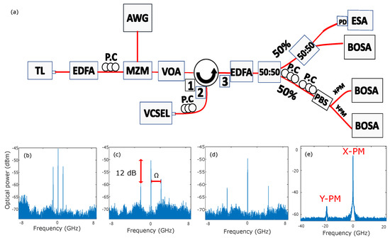
Figure 1.
(a) Setup for frequency comb injection into a single-mode VCSEL. TL: Tunable Laser, EDFA: amplifier, P.C: Polarization Controller, AWG: Arbitrary Waveform Generator, MZM: Mach–Zehnder Modulator, VOA: Variable Optical Attenuator, OSA: Optical Spectrum Analyser, PD: photodiode, ESA: Electrical spectrum analyzer. (b–d) correspond to the optical spectra of the injected comb for comb spacing of GHz, GHz and GHz, respectively. (e) shows the optical spectrum of the VCSEL in free running.
2.2. Impact of the Injected Comb Spacing
We first analyze the nonlinear polarization dynamics of a VCSEL under a narrow optical comb injection. To this end, we fix the bias current at I = 6 mA and then scan the plane of injection parameters, namely the detuning frequency and injected power that leads to various polarization mode competition. That bias current corresponds to a relaxation oscillation frequency of GHz. Figure 2 describes the sequence of bifurcations leading to the excitation of the normally depressed polarization mode (Y-PM) accompanied by unlocked time-periodic dynamics, which extends the injected comb to a much broader optical spectrum. Figure 2 is obtained for a small injected comb spacing, GHz and fixed detuning frequency GHz when varying the injected power, . The VCSEL output shows stable free-running operation at a very low injected power (see Figure 2a). A small increase in the injected power destabilizes the VCSEL output to modulated signal as a result of nonlinear wave-mixing in the dominant polarization mode (X-PM) (Figure 2b). In agreement with our previous publications [26,27], this nonlinear wave mixing takes place at the detuning frequency and a new frequency that depends on the injected comb spacing. The number of frequency lines involved in the nonlinear wave-mixing decreases with the injected power, as shown in Figure 2c. The VCSEL output is then an unstable comb with a high noise pedestal in X-PM at the injected comb repetition rate. By fine-tuning the injected power, instead of stabilizing the comb in a single polarization mode, a new bifurcation scenario results in the excitation of the free-running normally depressed polarization mode of the VCSEL. Interestingly, this polarization mode competition induces in the VCSEL two optical frequency combs with orthogonal polarization directions, as seen in Figure 2d. The two polarization combs have comparable power and the same repetition rate as the injected one with nine frequency lines in the X-PM comb and eight in the Y-PM comb at −30 dB from the maximum. The strongest comb line in the optical spectrum of Y-PM appears at the frequency position of the free-running Y-PM, i.e., its frequency position is ruled by the VCSEL linear birefringence. When we keep increasing the injected power, harmonic frequency comb dynamics takes place simultaneously in the two polarization combs, as shown in Figure 2e,f. The harmonic comb dynamics result in a reduction in comb repetition rate. Subharmonic bifurcations are well studied and understood phenomena that occur naturally in periodically forced oscillators [41]. Subharmonic dynamics have been expected to be a form of frequency locking different from the Adler type in diode laser optically injected with optical comb [24,25]. They appear when the detuning frequency is close to the rational fraction of the injected comb spacing. When we increase the injected power, the harmonic polarization comb destabilizes to complex polarization dynamics in X-PM and Y-PM (Figure 2g). It is worth observing that the X-PM still shows some remarkable comb lines at the repetition rate of the injected comb. A further increase in injected power results in a progressive suppression of all the power in the depressed polarization mode Y-PM accompanied by the stabilization of the comb dynamics in the dominant polarization mode X-PM, as seen in Figure 2h,i. Such single-polarization comb has the same repetition rate as the injected one.
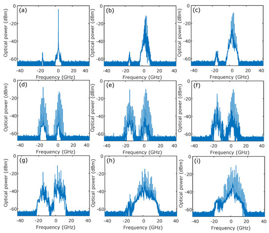
Figure 2.
Bifurcation scenarios resulting in the excitation of the depressed polarization mode. These optical spectra are obtained for detuning GHz and injected comb spacing GHz when increasing the injected power, . (a) Stable output at µW, (b,c) wave mixing at µW and µW, respectively, (d) two polarization comb at µW, (e,f) two polarization harmonics comb at µW and µW, respectively, (g) two polarization complex dynamics at µW and (h,i) X-polarization comb at µW and µW, respectively.
Figure 3 shows the polarization resolved optical spectra for comb dynamics in Figure 2d–f. Figure 3 confirms that the total VCSEL output combs shown in Figure 2d–f are formed by two combs with orthogonal polarization. In the optical spectrum of X-PM (Y-PM), we observed some comb lines at the frequency position of Y-PM (X-PM). This is due to the extension ratio of the polarization controllers.

Figure 3.
Polarization resolved-optical spectra corresponding to an example of two polarization comb dynamics similar to Figure 2d–f for detuning GHz and injected power µW. (a–c) correspond to the optical spectra of Y-PM, X-PM and the superposition of Y-PM and X-PM, respectively.
We have shown in Figure 2 the possibility of two orthogonal combs generation from polarization mode competition in a single-mode VCSEL. As discussed earlier in the introduction, the tunability of the optical frequency comb is a key property for many applications. In order to demonstrate tuning capability, we show in Figure 4 bifurcation scenarios inducing two polarization comb dynamics for the same detuning GHz when increasing the injected comb spacing to GHz. Similarly for GHz comb injection, the VCSEL output at low injected power shows the free-running operation, which bifurcates to nonlinear wave mixing due to a modulation involving detuning and injected comb spacing. In agreement again with Figure 2, wave-mixing results in a two polarization combs generation. Most importantly, despite the comparable power of the two polarization combs, the numbers of lines in X-PM and Y-PM have significantly decreased compared to GHz comb injection case. Indeed, the number of frequency lines in each polarization mode has decreased to achieve 3 at −30 dB from the maximum. It is important to notice that the two polarization comb dynamics are observed in a very small area of injection parameters for GHz comb injection. We have checked by using polarization resolved optical spectra that these total combs are formed by two micro-comb with orthogonal polarization in single-mode VCSEL, as shown in Figure 5. A small increase in the injected power destabilizes VCSEL to more complex dynamics in each polarization mode, as shown in Figure 4d. We have checked that the size of the two polarization comb region shrinks when increasing the injected comb spacing until it disappears at GHz. Figure 6 shows how to overcome this limitation. Similarly to GHz comb injection, complex polarization dynamics bifurcates to the single-polarization comb in X-PM. This polarized comb has an important noise pedestal and, therefore, deteriorating the comb performances. Interestingly, we have also checked that the two polarization comb dynamics in the single-mode VCSEL under parallel optical injection are not observed when the bias current is below mA. In contrast, when the polarization of the injected comb is orthogonal to that of VCSEL, the two polarization comb dynamics is always observed, whatever the bias current is.
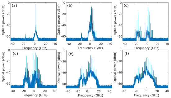
Figure 4.
Bifurcation scenarios resulting in the excitation of the depressed polarization mode. These optical spectra are obtained for detuning GHz and injected comb spacing GHz. (a) Stable output at µW, (b) wave mixing at µW, (c) two polarizations comb at µW, (d) two polarization harmonics comb at µW, (e) two polarization complex dynamics at µW and (f) X-polarization comb at µW.
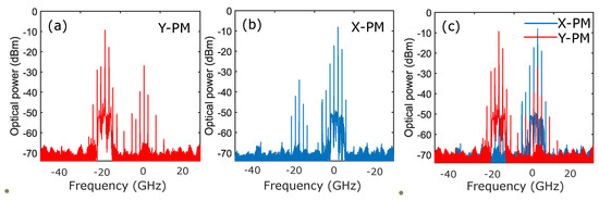
Figure 5.
Polarization resolved-optical spectra corresponding to an example of two polarization comb dynamics in Figure 4c. (a–c) are obtained for detuning GHz and injected power µW. (a–c) correspond to the optical spectra of Y-PM, X-PM and the superposition of Y-PM and X-PM, respectively.
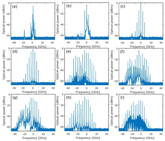
Figure 6.
Bifurcation scenarios resulting in the excitation of the depressed polarization mode. These optical spectra are obtained for detuning GHz and injected comb spacing GHz. (a,b) Wave mixing at µW and µW, respectively, (c,d) single polarization comb at µW and µW, respectively, (e,h,i) two polarizations comb at µW, µW and µW, respectively, (f) two polarization harmonics comb at µW and (g) two polarization complex dynamics at µW.
2.3. Influence of the Injection Current
We next increase the injected comb spacing to GHz and the bias current to mA, which is 2.67 times the threshold current. Such bias currents have been used in VCSELs to observe various nonlinear dynamics in the presence of single-mode injection with parallel polarization [37,39]. Compared to the mA bias current injection where nonlinear wave-mixing is accompanied by two polarization comb as a result of excitation of the normally depressed polarization mode, the VCSEL output bifurcates to selective amplification of the central injected lines in X-PM, as shown in Figure 6a–c. As observed in Figure 6c,d, selective amplification smoothly induces a broad optical comb characterized by the appearance of new frequency lines. When we increase the injected power, polarization mode competition results in the extension of the polarized comb to a much broader optical spectrum, as shown in Figure 6e. We checked through polarization resolved-optical spectra in Figure 7 that this overall comb corresponds to two combs based on the linear orthogonal polarization of the VCSEL. It is also possible to control the power in each polarization mode by fine-tuning the detuning. The two polarization combs and the polarized comb have the same repetition rate as the injected comb. By fine-tuning the injected power, the noise pedestal smoothly increases accompanied by harmonics comb line generation simultaneously in the two polarization combs as shown in Figure 6e. The harmonic comb significantly increases the number of resulting output lines and gives rise to a new comb with a low repetition rate ( GHz in Figure 6e). Most importantly, Figure 6e highlight a new possibility of broadband GHz comb generation using the same injection technique as in Figure 4c,d. When we keep increasing the injected power, the harmonics comb destabilizes to complex dynamics with remarkable frequency comb lines mainly around the dominant polarization mode (X-PM), as seen in Figure 6g. Interestingly, when further increasing injected power, VCSEL bifurcates again to the new broadband comb encompassing the two polarization modes with a significant increase in noise pedestal, as shown in Figure 6h,i. Similarly to Figure 6e, this overall comb is formed by two combs with the orthogonal polarization direction. The noise pedestal increases again with the injected power to deteriorate comb performance, such as CNR and comb bandwidths. We have shown that the properties (bandwidth and CNR) of the two polarization combs induced by parallel optical injection are limited by increasing the injected comb spacing for fixed bias current. However, the increase in bias current is, therefore, an alternative to improve polarization combs properties.

Figure 7.
Polarization resolved-optical spectra corresponding to an example of two polarization comb dynamics in Figure 6e–i. (a–c) are obtained for detuning GHz and injected power µW. (a–c) correspond to the optical spectra of Y-PM, X-PM and the superposition of Y-PM and X-PM, respectively.
2.4. Tailoring Comb Properties
Figure 8 provides further insight in comb dynamics when varying injection parameters, the injection current in the VCSEL and the polarization of injected light. Figure 8a,b analyze the comb properties for an injected comb spacing of GHz and fixed detuning, GHz. For the measurement of comb bandwidth, we consider an output comb line when its amplitude lies above −30 dB from the maximum amplitude in the optical spectrum. When the spectrum total optical comb shows a big dip, the total comb bandwidth is estimated from the separate bandwidth of X-PM and Y-PM spectra. The polarization of the injected comb is parallel to that of the free-running VCSEL. When increasing injected power, the comb bandwidth for mA and mA current reaches a maximum of around µW and µW, respectively, as shown Figure 8a. The decrease in comb bandwidth is due to the bifurcation of the two polarization comb to a single polarization comb generation in X-PM, as shown in Figure 2i and Figure 4f. Figure 8b shows that the best CNR is found for low injected power . CNR decreases with injected power due to the increase in the noise pedestal, which destabilizes comb properties. Figure 8a,b also show that the comb bandwidth and CNR increase with the injection current for the same injected comb properties. We next highlight the impact of polarization of the injected comb lines on VCSEL output comb dynamics in Figure 8c,d. In Figure 8c,d, blue and red correspond to parallel and orthogonal optical injection cases, respectively. As discussed in [28], the two polarization comb dynamics are mainly observed when VCSEL is injected between the two linear polarizations. However, for parallel optical injection, the two polarizations combs are observed only when the central injected comb lines are close to the dominant polarization mode of the VCSEL (detuning close to zero) at low injection currents, as shown in Figure 8a,b. When the injection current increases, the two comb dynamics are observed in a large portion of the plane of the injection parameters. Figure 8c shows that comb bandwidth increases with the injected power in the parallel and orthogonal optical injection case, which is in agreement with our previous publication [26,27,28]. Interestingly, the comb bandwidth for parallel optical injection is better than orthogonal optical injection at high injection currents, as shown in Figure 8c. When comparing Figure 8a to [28], we can observe that the comb bandwidth at low injection current is better for orthogonal than parallel optical injection. We also checked that optical comb performances do not change with the increase in injection currents. In the case of parallel optical injection, the improvement in the comb performance with the increase in the injection current is due to polarization mode instability, i.e., the excitation of the depressed polarization mode in the VCSEL at a large injection current. The excitation of the free-running depressed polarization mode in the VCSEL has been recently analyzed in several studies [37,39,40]. In these works, VCSEL was injected with a single frequency line master laser, and the injection current was higher than two-times the threshold current of VCSEL. The influence of the polarization of the injected comb is more impactful when we consider CNR. Figure 8d shows the CNR of comb dynamics induced by parallel (blue) and orthogonal (red) optical injections. We observe that, for parallel optical injection, whatever is the injected comb spacing and the injection current, the best CNR is found at low injected power and then decreases due to the increase in noise pedestal, as shown in Figure 6d–f. As shown in Figure 8b,d, the best values of CNR are found at low injections for orthogonal and parallel optical injections, which is in agreement with [28].
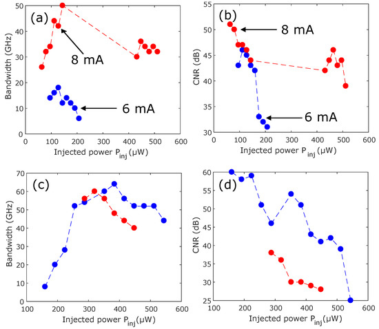
Figure 8.
Control of comb properties using the injection parameters and polarization of the injected light. (a,b) are obtained for fixed detuning and comb spacing GHz and GHz, respectively. (c,d) are obtained for fixed comb spacing ( GHz) and injection current mA. The blue and red curves correspond to the parallel and orthogonal optical injection, respectively. The comb dynamics in parallel and orthogonal optical injection are obtained for fixed detuning GHz and GHz, respectively.
3. Theoretical Bifurcation Analysis
In addition to experimental results, theoretical studies have been performed to provide further insight into the polarization dynamics of comb injected VCSELs. We have used the Spin-Flip Model (SFM) [42], which is widely used to describe polarization dynamics in free-running VCSELs and supplemented it with additional term describing optical comb injection. SFM parameters are chosen such that the dominant polarization mode (normally depressed polarization mode) of the VCSEL in free-running emits along the X-axis ((Y-axis). Model equations are given in Equations (1)–(4). In these equations, and are the two linearly polarized slowly varying components of the complex fields in the X and Y directions, respectively. D and n are the sum and the difference between the population inversions for spin-up and spin-down radiation channels. is the normalized current injection.
The meaning of the remaining SFM parameters is the following: and correspond to linear birefringence and linear dichroism, respectively; is the spin-flip relaxation rate, is the decay rate of D, is the field decay rate and is the linewidth enhancement factor.
The complex electrical field of the injected comb is written as follows:
with angular frequency and amplitude corresponding to comb lines and coupling coefficient . We consider an optimal coupling between the VCSEL output and the injected comb, which correspond to . We consider a comb with three frequency lines and we simplify the calculations by supposing , i.e., the phase of the individual injected comb lines is zero. The detuning frequency is the difference between and the intermediate frequency between those of X and Y polarizations, , with and , the frequency corresponding to the linear polarization mode X and Y, respectively.
SFM parameters are taken as ns, ns, , , GHz, ns and ns. These numerical values are taken from [38]. In the following, we shall use for injection strength, with , where and are the total amplitude of the injected field and the total amplitude of the VCSEL in free-running mode, respectively. Rate Equations (1)–(4) are numerically integrated using a fourth-order Runge–Kutta method. Numerical simulations are typically performed with a times series of 200 ns and a time step equal to 1.2 ps. The detuning frequency value is defined from the central injected comb line and is referred to as . In this section, we model the experiment by considering that the difference between the amplitude of the central injected comb line and the side comb lines is 12 dB.
3.1. Y-PM Comb Dynamics
Experimental results have demonstrated the possibility of generating two combs with orthogonal polarization in a VCSEL subject to parallel optical injection. We have also shown that this polarization comb performance is limited by the increase in injected comb spacing. In Figure 9, we analyze the two polarization comb numerically by using bifurcation diagrams. Figure 9 is obtained for fixed injected comb spacing GHz and detuning GHz. These bifurcation diagrams are plotted by selecting the minima and the maxima of polarization-resolved intensities, , for each injection strength. In Figure 9, the left and right panels correspond to the bifurcation diagrams of X-PM and Y-PM, respectively. Figure 9(a,b) show the bifurcation diagrams for fixed linear dichroism ns. When increasing the injection strength, the VCSEL output first shows a nonlinear wave-mixing involving the detuning and the injected comb spacing in X-PM. When we kept increasing the injection strength, wave mixing bifurcates to periodic dynamics corresponding to the optical frequency comb in the two linear orthogonal polarization modes. The two polarization comb region is referred to as “comb” in Figure 9. The X-PM shows a larger number of lines than the Y-PM, but the number of lines in Y-PM can be controlled with injection parameters. The two comb dynamics remain stable with a simultaneous increase in the number of lines over a large range of injection strengths. Interestingly, by finetuning the injection strength, the VCSEL output shows harmonic comb dynamics simultaneously in the two orthogonal combs at the boundary of the comb regions. A further increase in injection strength results in complex dynamics in X-PM and Y-PM accompanied by the abrupt suppression of all power in Y-PM. Cascade comb dynamics resulting in a very low comb repetition rate are observed in between complex dynamics depending on injection parameters. The complex polarization dynamics bifurcate to a single polarization comb in the dominant polarization mode (X-PM). We next vary linear dichroism to highlight its impact on the two polarization comb dynamics. Interestingly, when decreasing linear dichroism, the size of the two polarization comb region decreases, as observed in Figure 9(a,a,b,b). The double horizontal arrows indicate how much the size of the combs’ regions decreases with the decrease in linear dichroism. It is worth observing that all bifurcation sequences are similar to the case of ns. When linear dichroism reaches ns, the two polarization comb disappear and Y-PM is suppressed, as shown in Figure 9(a,b). Therefore, with the exception of the disappearance of comb lines in Y-PM, the bifurcation scenarios remain similar for X-PM. The bifurcation scenarios described in Figure 9 are in a very good agreement with the experimental ones in Figure 2 and Figure 4.
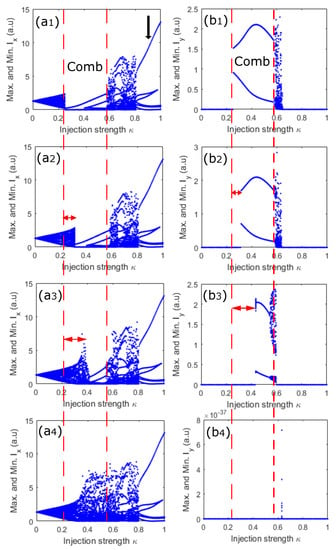
Figure 9.
Bifurcation diagrams for fixed injected comb spacing GHz and detuning GHz. The left and right panels correspond to X-polarization mode (X-PM) and Y-polarization mode (Y-PM). (a,b), (a,b), (a,b) and (a,b) are obtained for ns, ns, ns and ns.
Figure 10 shows an example comb and complex dynamics in the two polarization modes. Figure 10(a,b) show the optical spectra of comb dynamics in X-PM and Y-PM, respectively. We observe clearly in these spectra that the bandwidth of the frequency comb in the injected polarization mode (X-PM) is larger than the comb in the depressed polarization mode, Y-PM. As discussed early in the experimental section, these X-PM and Y-PM combs can combine to form a broad comb in the total output power of the VCSEL. Figure 10(a,b) show an example of complex polarization dynamics. Depending on injection parameters and injected comb properties, these complex polarization dynamics can simultaneously bifurcate to a two polarization harmonic comb or single-polarization comb.
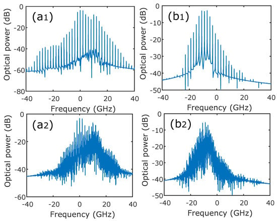
Figure 10.
Optical spectra for fixed GHz, GHz and ns. The left (a) and right (b) panels correspond to X-PM and Y-PM, respectively. The top figures (a,b) are obtained for and the bottom figures (a,b) are obtained for .
Figure 9 has shown that the decrease in linear dichroism results in the complete suppression of the comb lines in the normally depressed polarization mode (Y-PM). In Figure 11, we provide a further insight on comb generation, whatever the linear dichroism is. To this end, we keep the parameters used to obtain Figure 9(a,b), and then we vary the bias current. When the normalized bias current reaches 2.9 times the threshold, i.e., , comb dynamics start to take place again in the two polarization modes, as observed in Figure 11a,b. Most importantly, the bifurcation scenarios giving rise to the two polarization comb dynamics remain similar to the case of . When we increase the bias current to in Figure 11c,d, the bifurcation to the two polarization comb dynamics remains similar to the case of . Interestingly, unlike the case of , where the two polarization becomes abruptly chaotic, the VCSEL output bifurcates to cascade harmonic comb dynamics in the two polarization modes. The two polarization harmonics comb results in the suppression of all the power in Y-PM and bifurcates and, therefore, to polarized comb generation in the X-PM. Interestingly, we checked that when the polarization of the injected comb is orthogonal to that of the VCSEL, the size of the two polarization combs area increases slightly when linear dichroism, , is decreased.
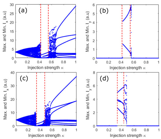
Figure 11.
Bifurcation diagrams for fixed injected comb spacing GHz and ns. The left and right panels correspond to X-PM and Y-PM, respectively. (a,b) are obtained for and (c,d) for .
3.2. Influence of Spin-Flip Relaxation Rate
Further insight into the two polarization comb dynamics is provided in Figure 12, where bifurcation diagrams are shown for fixed GHz when varying the injection strength together with the spin-flip relaxation rate . The blue and red colors in Figure 12 correspond to the bifurcation diagrams of X-PM and Y-PM, respectively. When is small (Figure 12a), the two polarization modes are excited at very low injection strengths. Most importantly, the comb lines start to progressively appear in each polarization mode as injection strength increases. Interestingly, when we keep increasing the spin-flip relaxation rate , the VCSEL output first shows the complex dynamics in the dominant polarization mode, which bifurcates to the excitation of the depressed polarization mode accompanied by comb generation, as shown in Figure 12b. The bifurcation sequence remains quite similar when further increasing the spin-flip relaxation rate. Still, the size of the complex dynamics region in X-PM increases, therefore resulting in a decrease in the size of the two combs region, as seen in Figure 12b–d. The size of the comb regions remains fixed at a high value of , as seen in Figure 12c,d. Unlike the case of Figure 12a,b, where the two polarization combs take place smoothly, the two comb appearance is abrupt when the spin-flip relaxation rate is large in Figure 12c,d. The two polarization comb dynamics bifurcates to a single polarization comb at large injection strength for each bifurcation diagram. It is worth observing that cascade harmonics characterizes bifurcation to single polarization comb dynamics at low . In contrast, the two complex polarization dynamics result in the single polarization comb at significant . Once the single polarization mode operation is achieved in VCSEL, bifurcation scenarios remain similar whatever the value the spin-flip relaxation rate is. In addition to the spin-flip relaxation rate, we have checked that the two polarization comb dynamics are observed in a wide range of SFM parameters including linear dichroism ( ns to ns), injection current ( to ), linewidth enhancement factor ( to ) and linear birefringence ( GHz to several hundred of GHz).
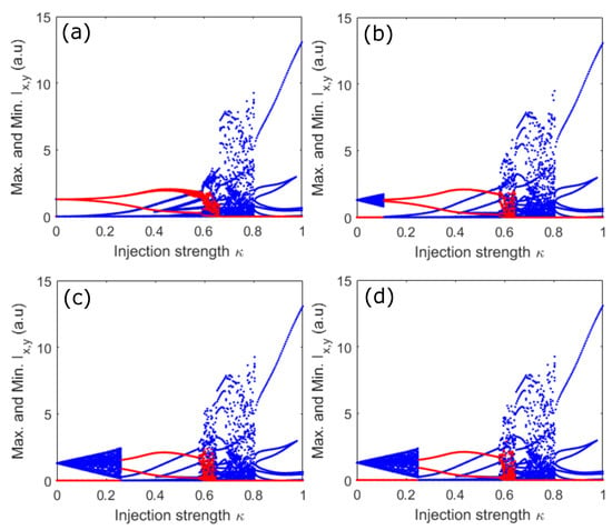
Figure 12.
Bifurcation diagrams for fixed injected comb spacing GHz and detuning GHz when varying . (a–d) are obtained for ns, ns, ns and ns, respectively.
4. Conclusions
We have shown experimentally and theoretically that VCSEL can bifurcate to interesting polarization dynamics under optical frequency comb injection. Interestingly, we have demonstrated that when the polarization of the injected comb is parallel to that of the VCSEL, polarization mode competition can induce two combs in a single-mode VCSEL. These combs are based on the two linear orthogonal polarizations in the VCSEL. We have also shown that these polarization combs are limited by an increase in the injected comb spacing, especially in the normally depressed polarization mode, Y-PM. Our results have shown that comb performance can be regained when increasing the bias current in VCSEL. We have performed numerical simulations to highlight a strong agreement with experimental results by using bifurcation diagrams. We have also numerically analyzed the influence of linear dichroism and the spin-flip relaxation rate on the two polarization comb dynamics. Interestingly, the two polarization comb area becomes narrower when linear dichroism decreases until it disappears at ns. By contrast, the size of the region of two polarizations comb dynamics increases with the decrease in linear dichroism when VCSEL is under an orthogonal optical injection. The single or two polarization combs induced by parallel optical injection are not as efficient in terms of bandwidth and CNR as the case of orthogonal comb injection investigated in [28] in terms of the number of lines at low bias current. Furthermore, two polarization combs are observed only if the bias current is significantly large, at least twice the threshold current for the VCSEL considered here. In the case of orthogonal optical injection, single and two polarization combs dynamics show the same performance (bandwidth and CNR), whatever the injection current is.
Author Contributions
Conceptualization, Y.D., D.W., K.P. and M.S.; Data curation, Y.D.; Formal analysis, Y.D.; Funding acquisition, Y.D.; Investigation, Y.D.; Methodology, D.W., K.P. and M.S.; Project administration, M.S.; Supervision, Y.D., D.W., K.P. and M.S.; Validation, D.W., K.P. and M.S.; Visualization, Y.D., D.W., K.P. and M.S.; Writing—original draft, Y.D.; Writing—review & editing, Y.D. All authors have read and agreed to the published version of the manuscript.
Funding
The presented study is funded by the Chaire Photonique: Ministère de l’Enseignement Supérieur, de la Recherche et de l’Innovation; Région Grand-Est; Département Moselle; European Regional Development Fund (ERDF); GDI Simulation; CentraleSupélec; Fondation CentraleSupélec; Fondation Supélec; Metz Metropole; and Fonds Wetenschappelijk Onderzoek (FWO) Vlaanderen Project No.G0E5819N.
Institutional Review Board Statement
Not applicable.
Informed Consent Statement
Not applicable.
Data Availability Statement
Data underlying the results presented in this paper are not publicly available at this time but may be obtained from the authors upon reasonable request.
Conflicts of Interest
The authors declare no conflict of interest.
References
- Sciamanna, M.; Shore, K.A. Physics and applications of laser diode chaos. Nat. Photonics 2015, 9, 151–162. [Google Scholar] [CrossRef] [Green Version]
- Wieczorek, S.; Krauskopf, B.; Simpson, T.B.; Lenstra, D. The dynamical complexity of optically injected semiconductor lasers. Phys. Rep. 2005, 416, 1–128. [Google Scholar] [CrossRef]
- Mogensen, F.; Olesen, H.; Jacobsen, G. Locking conditions and stability properties for a semiconductor laser with external light injection. IEEE J. Quantum Electron. 1985, 21, 784–793. [Google Scholar] [CrossRef]
- Larsson, A. Advances in VCSELs for Communication and Sensing. IEEE J. Sel. Top. Quantum Electron. 2011, 17, 1552–1567. [Google Scholar] [CrossRef]
- Sciamanna, M.; Panajotov, K.; Thienpont, H.; Veretennicoff, I.; Mégret, P.; Blondel, M. Optical feedback induces polarization mode hopping in vertical-cavity surface-emitting lasers. Opt. Lett. 2003, 28, 1543–1545. [Google Scholar] [CrossRef] [PubMed]
- Sciamanna, M.; Panajotov, K. Route to polarization switching induced by optical injection in vertical-cavity surface-emitting lasers. Phys. Rev. A 2006, 73, 023811. [Google Scholar] [CrossRef]
- Altés, J.B.; Gatare, I.; Panajotov, K.; Thienpont, H.; Sciamanna, M. Mapping of the dynamics induced by orthogonal optical injection in vertical-cavity surface-emitting lasers. IEEE J. Quantum Electron. 2006, 42, 198–207. [Google Scholar]
- Choquette, K.D.; Schneider, R.P.; Lear, K.L.; Leibenguth, R.E. Gain-dependent polarization properties of vertical-cavity lasers. IEEE J. Sel. Top. Quantum Electron. 1995, 1, 661–666. [Google Scholar] [CrossRef] [Green Version]
- Hurtado, A.; Quirce, A.; Valle, A.; Pesquera, L.; Adams, M.J. Nonlinear dynamics induced by parallel and orthogonal optical injection in 1550 nm vertical-cavity surface-emitting lasers (VCSELs). Opt. Express 2010, 18, 9423–9428. [Google Scholar] [CrossRef] [PubMed] [Green Version]
- Gatare, I.; Buesa, J.; Thienpont, H.; Panajotov, K.; Sciamanna, M. Polarization switching bistability and dynamics in vertical-cavity surface-emitting laser under orthogonal optical injection. Opt. Quantum Electron. 2006, 38, 429–443. [Google Scholar] [CrossRef]
- Virte, M.; Panajotov, K.; Thienpont, H.; Sciamanna, M. Deterministic polarization chaos from a laser diode. Nat. Photonics 2013, 7, 60–65. [Google Scholar] [CrossRef] [Green Version]
- Quirce, A.; de Dios, C.; Valle, A.; Acedo, P. VCSEL-based optical frequency combs expansion induced by polarized optical injection. IEEE J. Sel. Top. Quantum Electron. 2018, 25, 1–9. [Google Scholar] [CrossRef]
- Minoshima, K.; Matsumoto, H. High-accuracy measurement of 240-m distance in an optical tunnel by use of a compact femtosecond laser. Appl. Opt. 2000, 39, 5512–5517. [Google Scholar] [CrossRef] [PubMed]
- Link, S.M.; Maas, D.; Waldburger, D.; Keller, U. Dual-comb spectroscopy of water vapor with a free-running semiconductor disk laser. Science 2017, 356, 1164–1168. [Google Scholar] [CrossRef] [PubMed] [Green Version]
- Marin-Palomo, P.; Kemal, J.N.; Karpov, M.; Kordts, A.; Pfeifle, J.; Pfeiffer, M.H.; Trocha, P.; Wolf, S.; Brasch, V.; Anderson, M.H.; et al. Microresonator-based solitons for massively parallel coherent optical communications. Nature 2017, 546, 274–279. [Google Scholar] [CrossRef] [PubMed] [Green Version]
- Hargrove, L.; Fork, R.L.; Pollack, M. Locking of He–Ne laser modes induced by synchronous intracavity modulation. Appl. Phys. Lett. 1964, 5, 4–5. [Google Scholar] [CrossRef]
- Del’Haye, P.; Schliesser, A.; Arcizet, O.; Wilken, T.; Holzwarth, R.; Kippenberg, T.J. Optical frequency comb generation from a monolithic microresonator. Nature 2007, 450, 1214–1217. [Google Scholar] [CrossRef] [Green Version]
- Tilma, B.W.; Mangold, M.; Zaugg, C.A.; Link, S.M.; Waldburger, D.; Klenner, A.; Mayer, A.S.; Gini, E.; Golling, M.; Keller, U. Recent advances in ultrafast semiconductor disk lasers. Light. Sci. Appl. 2015, 4, e310. [Google Scholar] [CrossRef] [Green Version]
- Hugi, A.; Villares, G.; Blaser, S.; Liu, H.; Faist, J. Mid-infrared frequency comb based on a quantum cascade laser. Nature 2012, 492, 229–233. [Google Scholar] [CrossRef]
- Silvestri, C.; Columbo, L.L.; Brambilla, M.; Gioannini, M. Coherent multi-mode dynamics in a quantum cascade laser: Amplitude-and frequency-modulated optical frequency combs. Opt. Express 2020, 28, 23846–23861. [Google Scholar] [CrossRef] [PubMed]
- Weber, C.; Columbo, L.L.; Gioannini, M.; Breuer, S.; Bardella, P. Threshold behavior of optical frequency comb self-generation in an InAs/InGaAs quantum dot laser. Opt. Lett. 2019, 44, 3478–3481. [Google Scholar] [CrossRef] [PubMed]
- Grillot, F.; Duan, J.; Dong, B.; Huang, H. Uncovering recent progress in nanostructured light-emitters for information and communication technologies. Light. Sci. Appl. 2021, 10, 156. [Google Scholar] [CrossRef] [PubMed]
- Villares, G.; Hugi, A.; Blaser, S.; Faist, J. Dual-comb spectroscopy based on quantum-cascade-laser frequency combs. Nat. Commun. 2014, 5, 5192. [Google Scholar] [CrossRef] [PubMed]
- Shortiss, K.; Lingnau, B.; Dubois, F.; Kelleher, B.; Peters, F.H. Harmonic frequency locking and tuning of comb frequency spacing through optical injection. Opt. Express 2019, 27, 36976–36989. [Google Scholar] [CrossRef] [Green Version]
- Lingnau, B.; Shortiss, K.; Dubois, F.; Peters, F.H.; Kelleher, B. Universal generation of devil’s staircases near Hopf bifurcations via modulated forcing of nonlinear systems. Phys. Rev. E 2020, 102, 030201. [Google Scholar] [CrossRef] [PubMed]
- Doumbia, Y.; Malica, T.; Wolfersberger, D.; Panajotov, K.; Sciamanna, M. Nonlinear dynamics of a laser diode with an injection of an optical frequency comb. Opt. Express 2020, 28, 30379–30390. [Google Scholar] [CrossRef]
- Doumbia, Y.; Malica, T.; Wolfersberger, D.; Panajotov, K.; Sciamanna, M. Optical injection dynamics of frequency combs. Opt. Lett. 2020, 45, 435–438. [Google Scholar] [CrossRef]
- Doumbia, Y.; Wolfersberger, D.; Panajotov, K.; Sciamanna, M. Tailoring frequency combs through VCSEL polarization dynamics. Opt. Express 2021, 29, 33976–33991. [Google Scholar] [CrossRef]
- Gatare, I.; Sciamanna, M.; Nizette, M.; Panajotov, K. Bifurcation to polarization switching and locking in vertical-cavity surface-emitting lasers with optical injection. Phys. Rev. A 2007, 76, 031803. [Google Scholar] [CrossRef]
- Gatare, I.; Sciamanna, M.; Buesa, J.; Thienpont, H.; Panajotov, K. Nonlinear dynamics accompanying polarization switching in vertical-cavity surface-emitting lasers with orthogonal optical injection. Appl. Phys. Lett. 2006, 88, 101106. [Google Scholar] [CrossRef]
- Valle, A.; Gatare, I.; Panajotov, K.; Sciamanna, M. Transverse mode switching and locking in vertical-cavity surface-emitting lasers subject to orthogonal optical injection. IEEE J. Quantum Electron. 2007, 43, 322–333. [Google Scholar] [CrossRef] [Green Version]
- Panajotov, K.; Gatare, I.; Valle, A.; Thienpont, H.; Sciamanna, M. Polarization-and transverse-mode dynamics in optically injected and gain-switched vertical-cavity surface-emitting lasers. IEEE J. Quantum Electron. 2009, 45, 1473–1481. [Google Scholar] [CrossRef]
- Gatare, I.; Panajotov, K.; Sciamanna, M. Frequency-induced polarization bistability in vertical-cavity surface-emitting lasers with orthogonal optical injection. Phys. Rev. A 2007, 75, 023804. [Google Scholar] [CrossRef]
- Nizette, M.; Sciamanna, M.; Gatare, I.; Thienpont, H.; Panajotov, K. Dynamics of vertical-cavity surface-emitting lasers with optical injection: A two-mode model approach. JOSA B 2009, 26, 1603–1613. [Google Scholar] [CrossRef]
- Sciamanna, M.; Panajotov, K. Two-mode injection locking in vertical-cavity surface-emitting lasers. Opt. Lett. 2005, 30, 2903–2905. [Google Scholar] [CrossRef] [PubMed]
- Hong, Y.; Spencer, P.S.; Rees, P.; Shore, K.A. Optical injection dynamics of two-mode vertical cavity surface-emitting semiconductor lasers. IEEE J. Quantum Electron. 2002, 38, 274–278. [Google Scholar] [CrossRef]
- Denis-le Coarer, F.; Quirce, A.; Valle, Á.; Pesquera, L.; Sciamanna, M.; Thienpont, H.; Panajotov, K. Polarization dynamics induced by parallel optical injection in a single-mode VCSEL. Opt. Lett. 2017, 42, 2130–2133. [Google Scholar] [CrossRef] [PubMed]
- Quirce, A.; Pérez, P.; Popp, A.; Valle, Á.; Pesquera, L.; Hong, Y.; Thienpont, H.; Panajotov, K. Polarization switching and injection locking in vertical-cavity surface-emitting lasers subject to parallel optical injection. Opt. Lett. 2016, 41, 2664–2667. [Google Scholar] [CrossRef] [Green Version]
- Quirce, A.; Popp, A.; Denis-le Coarer, F.; Pérez, P.; Valle, Á.; Pesquera, L.; Hong, Y.; Thienpont, H.; Panajotov, K.; Sciamanna, M. Analysis of the polarization of single-mode vertical-cavity surface-emitting lasers subject to parallel optical injection. JOSA B 2017, 34, 447–455. [Google Scholar] [CrossRef]
- Denis-le Coarer, F.; Quirce, A.; Pérez, P.; Valle, A.; Pesquera, L.; Sciamanna, M.; Thienpont, H.; Panajotov, K. Injection locking and polarization switching bistability in a 1550 nm VCSEL subject to parallel optical injection. IEEE J. Sel. Top. Quantum Electron. 2017, 23, 1–10. [Google Scholar] [CrossRef]
- Guckenheimer, J.; Holmes, P. Nonlinear Oscillations, Dynamical Systems, and Bifurcations of Vector Fields; Springer Science & Business Media: Berlin/Heidelberg, Germany, 2013; Volume 42. [Google Scholar]
- San Miguel, M.; Feng, Q.; Moloney, J.V. Light-polarization dynamics in surface-emitting semiconductor lasers. Phys. Rev. A 1995, 52, 1728. [Google Scholar] [CrossRef]
Publisher’s Note: MDPI stays neutral with regard to jurisdictional claims in published maps and institutional affiliations. |
© 2022 by the authors. Licensee MDPI, Basel, Switzerland. This article is an open access article distributed under the terms and conditions of the Creative Commons Attribution (CC BY) license (https://creativecommons.org/licenses/by/4.0/).