Abstract
Generalized optical multiple-input multiple-output (GOMIMO) techniques have been recently shown to be promising for high-speed optical wireless communication (OWC) systems. In this paper, we propose a novel deep learning-aided GOMIMO (DeepGOMIMO) framework for GOMIMO systems, wherein channel state information (CSI)-free detection can be enabled by employing a specially designed deep neural network (DNN)-based MIMO detector. The CSI-free DNN detector mainly consists of two modules: one is the preprocessing module, which is designed to address both the path loss and channel crosstalk issues caused by MIMO transmission, and the other is the feedforward DNN module, which is used for joint detection of spatial and constellation information by learning the statistics of both the input signal and the additive noise. Our simulation results clearly verify that, in a typical indoor 4 × 4 MIMO-OWC system using both generalized optical spatial modulation (GOSM) and generalized optical spatial multiplexing (GOSMP) with unipolar nonzero 4-level pulse-amplitude modulation (4-PAM) modulation, the proposed CSI-free DNN detector achieves near the same bit error rate (BER) performance as the optimal joint maximum-likelihood (ML) detector, but with much-reduced computational complexity. Moreover, because the CSI-free DNN detector does not require instantaneous channel estimation to obtain accurate CSI, it enjoys the unique advantages of improved achievable data rate and reduced communication time delay in comparison to the CSI-based zero-forcing DNN (ZF-DNN) detector.
1. Introduction
Due to the exhaustion of radio frequency (RF) spectrum resources, optical wireless communication (OWC) which explores the infrared, visible light, or ultraviolet spectrum has been envisioned as a promising candidate to satisfy the ever-increasing data demand in future indoor environments [1]. In recent years, bidirectional OWC, which is also named light fidelity (LiFi), has been widely considered as one of the key enabling technologies for 5G/6G and Internet of things (IoT) communications [2,3,4,5]. Although OWC systems have many inherent advantages such as abundant license-free spectrum resources, no electromagnetic interference (EMI) and enhanced physical-layer security, the practically achievable capacity of OWC systems is largely limited by the small modulation bandwidth of commercial off-the-shelf (COTS) optical elements, especially for illumination light-emitting diodes (LEDs) [6].
As a very natural way to efficiently improve the achievable capacity of indoor OWC systems that use LEDs, multiple-input multiple-output (MIMO) transmission has attracted great attention recently, which fully exploits the existing LED fixtures in the ceiling of a typical room to harvest substantial diversity or multiplexing gain [7,8,9]. So far, various optical MIMO techniques have been introduced for OWC systems, among which optical spatial multiplexing (OSMP) and optical spatial modulation (OSM) are two of the most popular. Specifically, OSMP can achieve a full multiplexing gain and hence a relative high spectral efficiency, but suffers from severe interchannel interference (ICI) [10]. In contrast, OSM can remove ICI by activating a single LED to transmit signal at each time slot. Although OSM can transmit additional index bits, only one constellation symbol can be transmitted at each time slot, and hence it is challenging for OSM systems to achieve high spectral efficiency [11]. Lately, generalized optical MIMO (GOMIMO) techniques, including generalized OSM (GOSM) and generalized OSMP (GOSMP), have been further proposed to boost the capacity of MIMO-OWC systems [12,13,14,15]. In GOSM systems, multiple LEDs are activated to transmit the same signal, and therefore more index bits can be transmitted and the diversity gain can also be increased. In GOSMP systems, only a subset of LEDs are activated to transmit different signals, resulting in reduced multiplexing gain. However, additional index bits can be transmitted, and the ICI can also been reduced in GOSMP systems.
In order to successfully implement GOMIMO systems, an efficient MIMO detection scheme should be adopted. Generally, the joint maximum-likelihood (ML) detector serves as the optimal detector for GOMIMO systems [16]. Nevertheless, the ML detector usually has high computational complexity, making it infeasible in practical applications. Instead, the combination of zero-forcing (ZF) equalization and ML detection can be a practical low-complexity detection scheme for GOMIMO systems [16]. However, ZF equalization inevitably leads to noise amplification due to high channel correlation in typical indoor MIMO-OWC systems. Moreover, the ZF-ML detector also suffers from the adverse effect of error propagation, because the detection error of spatial symbols might propagate to the estimation of constellation symbols.
With the rapid development of machine learning technology, machine learning has revealed its great potential in wireless communication systems [17,18]. Moreover, machine learning techniques have also been widely applied in optical communication systems. In [19], a distributed collaborative learning approach was proposed for cognitive and autonomous multidomain elastic optical networking. In [20], two machine learning algorithms were proposed for bit error rate (BER) degradation detection and failure identification in elastic optical networks. In [21], a machine learning method was proposed for quality of transmission prediction of unestablished lightpaths. In [22], a convolutional neural networks-based error vector magnitude estimation scheme was proposed for fast and accurate signal quality monitoring in coherent optical communications. In [23], a long-short-term-memory (LSTM) algorithm was proposed to mitigate transmission impairments of 4-level pulse-amplitude modulation (PAM4) produced by silicon-microring modulator. Most recently, deep learning techniques have been further introduced in OWC systems for binary signaling design [24], mitigation of both linear and nonlinear impairments [25], energy-efficient resource management [26], and so on. More specifically, a ZF-based deep neural network (DNN)-detection scheme has been proposed for MIMO detection in GOMIMO systems [27]. The obtained results in [27] show that the ZF-DNN detector can achieve comparable BER performance as the optimal joint ML detector with greatly reduced computational complexity. Nevertheless, the ZF-DNN detector takes the ZF equalized signal as its input, which requires accurate channel state information (CSI), i.e., the MIMO channel matrix, to successfully perform ZF equalization. Although CSI can be estimated by using training symbols [28], training-based instantaneous channel estimation inevitably causes both the loss of achievable data rate and the increase of communication time delay.
In this paper, to address the disadvantages of CSI-based ZF-DNN detection due to the requirement of instantaneous CSI for ZF equalization, we for the first time propose a DeepGOMIMO framework for GOMIMO systems where CSI-free MIMO detection is achieved by a novel DNN detection scheme. By adding a specially designed preprocessing module before the feedforward DNN module, CSI-free detection can be successfully enabled for GOMIMO systems. The key difference between our previous work [15] and this current work can be described as follows: our previous work [15] mainly proposed four OFDM-based GOMIMO schemes, whereas this current work proposes a CSI-free DNN detection scheme for PAM-based GOMIMO systems. Numerical simulations are extensively conducted to evaluate the performance of the proposed CSI-free DNN detector, which is also compared with other three benchmark schemes including the joint ML detector, the ZF-ML detector and the ZF-DNN detector. Our simulation results verify the advantages of the proposed CSI-free DNN detector in comparison to other benchmark schemes in GOMIMO systems. To the best of our knowledge, it is the first time that a CSI-free DNN detection scheme is proposed and evaluated in detail for PAM-based GOMIMO systems.
The rest of this paper is organized as follows. In Section 2, we describe the mathematical model of a general GOMIMO system. In Section 3, we introduce four detection schemes for GOMIMO systems. Detailed simulation setup and results are presented in Section 4. Finally, Section 5 concludes the paper.
2. System Model
In this section, we introduce the mathematical model of a general GOMIMO system equipped with LEDs and photodetectors (PDs). The channel model is first described, and then the basic principle of GOMIMO is further reviewed.
2.1. Channel Model
Letting x be the transmitted signal vector, represent the MIMO channel matrix and denote the additive noise vector, the received signal vector is obtained by
and the corresponding channel matrix can be expressed by
where () denotes the direct current (DC) channel gain between the r-th PD and the t-th LED. Assuming that each LED follows the general Lambertian radiation pattern and only the line-of-sight (LOS) transmission is considered, is calculated by [29]
In Equation (3), denotes the Lambertian emission order, with being the semiangle at half power of the LED; and A represent the responsivity and the physical area of the PD, respectively; is the distance between the r-th PD and the t-th LED; and are the emission angle and the incident angle, respectively. is the gain of optical filter, and is the gain of optical lens, where n and are the refractive index and the half-angle field-of-view (FOV) of the optical lens, respectively.
Moreover, the additive noise in typical OWC systems consists of both shot and thermal noises, and it is reasonable to model the additive noise as a real-valued zero-mean additive white Gaussian noise (AWGN) [8]. Letting denote the noise power spectral density (PSD) and B be the signal bandwidth, the power of the additive noise is given by .
2.2. Principle of GOMIMO
The concept of GOMIMO was first proposed in [15], which aims to fully explore the potential of MIMO transmission for spectral efficiency enhancement of bandlimited OWC systems. Specifically, GOMIMO techniques can be generally divided into two main categories: one is GOSM, in which all the activated LED transmitters transmit the same signal, and the other is GOSMP, in which the activated LED transmitters transmit different signals. For more details about the GOMIMO techniques, please refer to our previous work [15].
Figure 1 illustrates the block diagram of a general GOMIMO system, where () LEDs are activated for signal transmission during GOMIMO mapping. As we can see, the input bits are first divided into two streams: one is fed into the constellation mapper which converts the binary bits into constellation symbols, and the other is sent into the LED index selector which selects the desired LEDs to transmit the generated constellation symbols accordingly. Based on the obtained constellation symbol vector and spatial index vector , GOMIMO (GOSM or GOSMP) mapping is performed to generate the transmitted signal vector . The mapping tables for GOSM and GOSMP with and are given in insets (a) and (b) of Figure 1, respectively. On the receiver side, the received signal vector is fed into the GOMIMO detector which finally yields the output bits. The detailed GOMIMO detection schemes will be discussed in the following section.
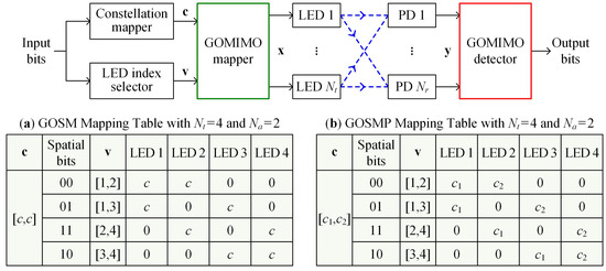
Figure 1.
Block diagram of a general GOMIMO system. Insets (a) and (b) show the mapping tables of GOSM and GOSMP, respectively.
In typical LED-based OWC systems, intensity modulation with direct detection (IM/DD) is generally applied due to the noncoherence nature of LEDs. As a result, only real-valued nonnegative signals can be successfully transmitted in the IM/DD OWC systems [29]. In this work, unipolar M-ary PAM (M-PAM) is adopted as the modulation format for GOMIMO systems. In order to avoid the loss of spatial information when performing GOMIMO mapping, the M-PAM symbols cannot have zero values [15]. Therefore, unipolar nonzero M-PAM modulation is utilized here and the corresponding intensity levels are given by
where denotes the average optical power emitted [8]. By using M-PAM modulation, the spectral efficiencies (bits/s/Hz) of the GOMIMO system with activated LEDs applying GOSM and GOSMP mappings are respectively given by
where denotes the floor operator, which outputs an integer smaller or equal to its input value and represents the binomial coefficient.
3. Detection Schemes for GOMIMO Systems
In this section, we first introduce two conventional detection schemes for GOMIMO systems by utilizing M-PAM modulation, including the optimal joint ML detection and the ZF-ML detection. After that, we further present two deep learning-aided detection schemes, including the CSI-based ZF-DNN detection and our newly proposed CSI-free DNN detection.
3.1. Joint ML Detection
Assuming perfect CSI, joint ML detection is the optimal detection scheme for GOMIMO systems with M-PAM modulation. More specifically, the joint ML detector estimates the transmitted constellation and spatial information simultaneously in a joint manner. By applying the joint ML detector, the transmitted signal vector can be estimated by
where denotes the modulus operator and represents the set of all the considered transmitted signal vectors.
Although the joint ML detection can achieve optimal performance, it suffers from high computational complexity. Therefore, it is usually not feasible to apply the joint ML detector in practical GOMIMO systems.
3.2. ZF-ML Detection
In order to avoid the high computational complexity of joint ML detection, a low-complexity ZF-ML detection scheme can be applied in GOMIMO systems, which is basically a three-step detection scheme [15,30]. In the first step, ZF equalization is performed for MIMO demultiplexing. The estimate of the transmitted signal vector after ZF equalization can be obtained by
where denotes the pseudoinverse of [10].
In the second step, ML detection is executed to obtain the estimate of the spatial index vector according to . Finally, in the third step, the estimate of the constellation symbol vector can be obtained accordingly by using and the estimate of the spatial index vector. For more details about the principle of ZF-ML detection for GOMIMO systems, please refer to our previous work [15].
Compared with joint ML detection, the computational complexity of ZF-ML detection is significantly reduced. Nevertheless, the performance of ZF-ML detection is also largely degraded in comparison to that of joint ML detection, which can be explained as follows. On the one hand, ZF equalization inevitably causes severe noise amplification due to the high channel correlation in typical MIMO-OWC systems [8], which might greatly degrade the performance of GOMIMO systems. On the other hand, the detection error of spatial symbols might propagate to the estimation of the constellation symbols [31], which leads to further substantial performance degradation of GOMIMO systems.
3.3. CSI-Based ZF-DNN Detection
To efficiently address both the high computational complexity issue of joint ML detection and the noise-amplification and error-propagation issues of ZF-ML detection, a ZF-DNN detection has been proposed for GOSMP systems in [27]. The key idea of the ZF-DNN detection scheme is to employ a feedforward DNN module to directly and simultaneously estimate the transmitted spatial and constellation bits by taking the ZF equalized signal vector as input. For more details about the implementation of the ZF-DNN detector, please refer to [31,32]. In a word, the feedforward DNN module can fulfill the tasks of spatial index vector estimation, constellation symbol vector estimation, spatial symbol demodulation, and constellation symbol demodulation at the same time. Simulation results in [27] clearly show that, by selecting a proper training signal-to-noise ratio (SNR), the ZF-DNN detector can achieve nearly the same BER performance as the optimal joint ML detector, but with a significantly reduced computational complexity.
Despite the near-optimal BER performance and low computational complexity of the ZF-DNN detector, it takes the ZF equalized signal vector as the input of the feedforward DNN module. As per (8), is obtained by multiplying the received signal vector with , i.e., the pseudoinverse of the channel matrix . Generally, the CSI (i.e., the channel matrix) can be efficiently estimated by transmitting training symbols [28]. Nevertheless, the use of training symbols for accurate CSI estimation inevitably reduces the achievable data rate of GOMIMO systems, especially for low SNR scenarios. Furthermore, because the channel matrix is highly related to the specific location of the MIMO receiver, i.e., the PD array, channel estimation needs to be executed instantaneously with the change of receiver location. In consequence, instantaneous channel estimation inevitably introduces additional communication time delay and computational complexity in practical GOMIMO systems.
3.4. Proposed CSI-Free DNN Detection
Considering the many disadvantages of CSI-based ZF-DNN detection due to the requirement of instantaneous CSI for ZF equalization, in this work, we for the first time propose a novel CSI-free DNN detection scheme for GOMIMO systems. Figure 2 depicts the schematic diagram of the proposed CSI-free DNN detector, which consists of a preprocessing module and a feedforward DNN module. It can be seen that a preprocessing module is placed in front of the feedforward DNN module in the proposed CSI-free DNN detector, which is the key to dealing with the impact of MIMO transmission through free-space channels and hence realize detection without the need of CSI. Specifically, as can be found from (1), the impact of MIMO transmission on the transmitted signal vector can be characterized from the following two aspects. First, because the channel coefficients in typical MIMO-OWC systems are within the region from to [8,33], the electrical path loss caused by MIMO transmission is about 80 to 120 dB. Secondly, MIMO transmission also inevitably leads to channel crosstalk, which might cause severe ICI, especially for GOSMP systems. As a result, the designed preprocessing module should be able to address both the path loss issue and the channel crosstalk issue caused by MIMO transmission.

Figure 2.
Schematic diagram of the proposed CSI-free DNN detector consisting of a preprocessing module and a feedforward DNN module.
As shown in Figure 2, our specially designed preprocessing module mainly contains two parts: one is the amplitude scaling part and the other is the feature-extraction part. Specifically, the amplitude scaling part is adopted to address the path loss issue by multiplying the received signal vector with a scaling factor . Note that a proper value is determined in advance for each receiver location in the GOMIMO system, and hence no instantaneous CSI is needed to achieve amplitude scaling. Moreover, the feature-extraction part is used to address the channel crosstalk issue, which multiplies the scaled received signal vector by a feature matrix . Hence, the output signal vector of the preprocessing module in the CSI-free DNN detector, i.e., , can be obtained by
In order to provide enough information for the following feedforward DNN module to efficiently learn and remove the impact of channel crosstalk caused by MIMO transmission, the feature matrix should be able to reflect all the potential signal superposition cases at the receiver side. Consequently, according to the mapping tables of both GOSM and GOSMP in Figure 1, we adopt the corresponding unified mapping matrix as the feature matrix, i.e.,
Subsequently, the preprocessed signal vector is fed into a feedforward DNN module, which mainly consists of an input layer, multiple hidden layers, an output layer, and a decision layer. Because is a vector with elements, the input layer contains neurons accordingly. Moreover, we set totally four fully connected hidden layers in the feedforward DNN module, which are used to learn the statistical characteristics of both the input signal and the additive noise. The number of neurons in the i-th () hidden layer is denoted by , and the rectified linear unit (ReLU) function, i.e., , is adopted as the activation function of the hidden layers. For the output layer, it adopts the Sigmoid function, i.e., , as the activation function to generate a fuzzy bit information, so as to map the output of each neuron within the range [0, 1]. Because the DNN detector takes the input binary bits corresponding to a transmitted signal vector as the output, both the output layer and the decision layer have the same number of neurons, which is equal to the spectral efficiency of the GOMIMO system, i.e., . Therefore, letting denote the output of the k-th () layer of the feedforward DNN module, the corresponding input–output relationship can be described by
where and with represent the corresponding weight matrix and the bias vector, respectively. According to (11), the mean-square error (MSE) loss can be calculated as follows:
where denotes the corresponding transmitted bit vector ans S is the length of .
Finally, the decision layer is utilized to determine the noninteger output of each neuron in the output layer to be 0 or 1. Letting denote the final output binary bit vector, the q-th () binary bit in can be estimated by
4. Simulation Results
In this section, we evaluate and compare the performance of four different detection schemes in a typical indoor GOMIMO system through numerical simulations.
4.1. Simulation Setup
In our simulations, we consider a 4 × 4 ( = = 4) GOMIMO system configured in a typical 5 m × 5 m × 3 m room. The 2 × 2 square LED array is placed at the center of the ceiling and the spacing between two adjacent LEDs is 2 m. The height of the receiving plane is 0.85 m, and two receiver locations over the receiving plane, i.e., the center (2.5 m, 2.5 m, 0.85 m) and the corner (0 m, 0 m, 0.85 m), are considered for performance evaluation. The receiver consists of a 2 × 2 square PD array, where the spacing between two adjacent PDs is 10 cm. For both GOSM and GOSMP mappings, two out of four LEDs are activated for signal transmission, i.e., = 2. Moreover, unipolar nonzero 4-PAM modulation is adopted in the GOMIMO system, and hence the corresponding spectral efficiencies for GOSM and GOSMP mappings are 4 and 6 bits/s/Hz, respectively. In addition, we adopt transmitted SNR as the measure to evaluate the BER performance of the GOMIMO system, which is defined as the ratio of the transmitted electrical signal power to the additive noise power [8,15]. The other simulation parameters of the GOMIMO system can be found in Table 1.

Table 1.
Simulation parameters.
The detailed parameters of the CSI-free DNN detectors for GOSM and GOSMP are given in Table 2. For GOSM, the number of neurons of four hidden layers is 128, 64, 32, and 16, respectively. The learning rate is 0.01 when the receiver is located at the center of the receiving plane, and it is reduced to 0.001 when the receiver is moved to the corner. Moreover, the scaling factors are set to and when the receiver is located at the center and the corner, respectively. For GOSMP, every hidden layer contains 64 neurons, and the learning rates are 0.01 and 0.005 when the receiver is located at the center and the corner of the receiving plane, respectively. In addition, the scaling factors of and are used for center and corner received locations, respectively. For both GOSM and GOSMP, the lengths of training set and validation set are assumed to be 150,000 and 50,000, respectively. In order to accelerate the convergence speed, we use the minibatch technique in training, and each minibatch contains 100 transmitted signal vectors.

Table 2.
Parameters of the DNN detector for GOSM and GOSMP.
4.2. MSE Loss
We first analyze the MSE loss of the proposed CSI-free DNN detector in the 4 × 4 GOMIMO system. Figure 3a,b show the MSE losses versus the number of epochs for GOSM and GOSMP, respectively, where the receiver is located at the center of the receiving plane. As we can see, the MSE loss decreases rapidly with the increase of training epochs for both GOSM and GOSMP. Moreover, the MSE loss is much reduced when a higher training SNR is used, especially for GOSMP. It can be seen from Figure 3a that the MSE loss for GOSM converges quickly with only a few epochs. For GOSMP, as shown in Figure 3b, about 20 epochs are required for the MSE loss to converge. Hence, owing to the use of the minibatch technique, the CSI-free DNN detector only requires a very limited number of epochs for efficient training, indicating that it can be deployed rapidly in practical applications.
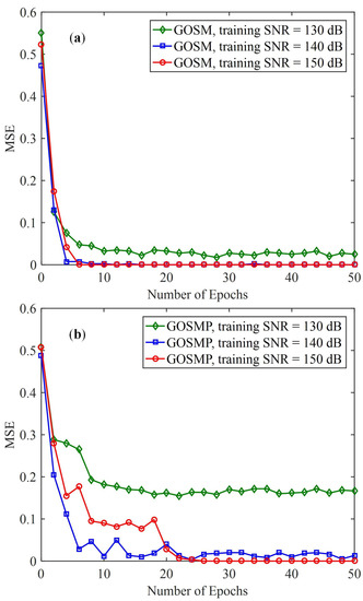
Figure 3.
MSE training loss of the proposed CSI-free DNN detector with receiver located at the center of the receiving plane for (a) GOSM and (b) GOSMP.
4.3. BER Performance
We further evaluate and compare the BER performance of the proposed CSI-free DNN detector with the other three benchmark detectors in the 4 × 4 GOMIMO system. Figure 4a,b compare the BER performance of four detectors for GOSM with the receiver located at the center and the corner of the receiving plane, respectively. When the receiver is located at the center of the receiving plane, as shown in Figure 4a, the ZF-ML detector requires a high transmitted SNR of 163.4 dB to achieve the target BER of . However, the required SNR to reach BER = is reduced to 138.9 dB for the joint ML detector. As a result, a substantial 24.5-dB SNR gain can be obtained by the joint ML detector in comparison to the ZF-ML detector, which is mainly because the ZF-ML detector suffers from severe noise amplification and error propagation. Moreover, it can be further seen that the ZF-DNN detector with an optimal 140-dB training SNR can achieve comparable BER performance as the joint ML detector in the high SNR region, suggesting the excellent error performance of the ZF-DNN detector under the condition of accurate CSI for ZF equalization. Finally, for our proposed CSI-free DNN detector, we investigate the impact of training SNR on its error performance and three different training SNRs of 130, 140, and 150 dB are considered. It is clearly shown that the CSI-free DNN detector with 140-dB training SNR achieves nearly the same BER performance as the joint ML detector across the whole SNR region, which slightly outperforms the ZF-DNN detector in the low SNR region. However, the joint ML detector outperforms the CSI-free DNN detector when a lower training SNR of 130 dB or a higher training SNR of 150 dB is adopted, and the reasons can be explained as follows. The DNN module can better learn the statistics of the noise with a relatively small training SNR, whereas the statistics of the data symbols can be more accurately learned when the training SNR is relatively large. As a result, there exists an optimal training SNR which can make a tradeoff for the DNN module to learn the statistics of both the noise and the data symbols and hence lead to a minimum overall BER. When the receiver is moved to the corner of the receiving plane, as shown in Figure 4b, we can observe that the joint ML detector outperforms the ZF-ML detector by an SNR gain of more than 40 dB at BER = , whereas the ZF-DNN detector with an optimal training SNR of 160 dB obtains near-optimal BER performance as the joint ML detector only for relatively low BERs. Furthermore, the CSI-free DNN detector achieves comparable BER performance as the joint ML detector in the high SNR region, which outperforms the ZF-DNN detector in the low SNR region. It should be noted that an error floor occurs for the CSI-free DNN detector with a lower training SNR of 140 dB, which is mainly due to the insufficient learning of the statistics of the data symbols in a very noisy environment.
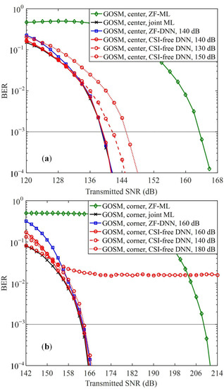
Figure 4.
BER comparison of the proposed CSI-free DNN detector and three benchmark detectors for GOSM at (a) the center and (b) the corner.
The BER versus transmitted SNR for GOSMP is plotted in Figure 5. As we can see, the ZF-DNN detector with an optimal training SNR can achieve very close performance as the joint ML detector when the receiver is located at the center of the receiving plane, but it performs worse than the joint ML detector when the receiver is moved to the corner, especially in the low SNR region. In contrast, the proposed CSI-free DNN detector can achieve comparable BER performance as the joint ML detector for both center and corner receiver locations. Moreover, error floors occur for the CSI-free DNN detector when the adopted training SNR is too small or too large. It can be further observed from Figure 4 and Figure 5 that the optimal training SNRs for the ZF-DNN detector and the CSI-free DNN detector at the same receiver location are generally the same in GOMIMO systems.
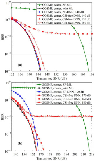
Figure 5.
BER comparison of the proposed CSI-free DNN detector and three benchmark detectors for GOSMP at (a) the center and (b) the corner.
4.4. Impact of Input Pre-Processing
It can be seen from Figure 2 that the preprocessing module, which preprocesses the input of the feedforward DNN module, plays a vital role to guarantee that the proposed CSI-free DNN detector can successfully perform MIMO detection without the need of CSI. In the next, we evaluate the impact of input preprocessing on the performance of the CSI-free DNN detector. Here, two different inputs of the feedforward DNN module are considered: one is , i.e., the preprocessing module only performs amplitude scaling, and the other is , i.e., the preprocessing module performs both amplitude scaling and feature extraction. Figure 6 compares the BER performance of the proposed CSI-free DNN detector where the feedforward DNN module having different inputs for both GOSM and GOSMP with the receiver located at the center of the receiving plane. As we can see, for GOSM, the BER performance is only slightly improved when the input is changed from to , and the SNR gain at BER = is only 0.8 dB. In contrast, for GOSMP, a noticeable BER improvement can be obtained by replacing the input with , and the corresponding SNR gain at BER = is increased to 2.4 dB. The difference between BER improvements for GOSM and GOSMP can be explained as follows. As discussed in Section 3.4, because the feature matrix contains the spatial mapping information of GOMIMO systems, the feedforward DNN module can use the spatial mapping information to remove the channel crosstalk. As a result, the feedforward DNN module with input can efficiently mitigate the adverse effect of error propagation. However, in GOSM systems, the activated LEDs are used to transmit the same signal and hence error propagation only leads to reduced diversity gain, which might not significantly degrade the BER performance. In contrast, because the activated LEDs transmit different signals in GOSMP systems, error propagation leads to the missing of constellation information and hence results in significant BER degradation.
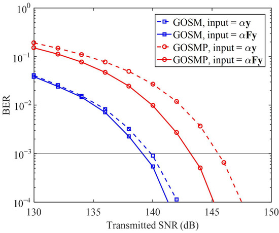
Figure 6.
BER comparison of the proposed CSI-free DNN detector where the feedforward DNN module having different inputs for both GOSM and GOSMP at the center of the receiving plane.
Due to the substantial path loss during MIMO transmission, the received signal needs to be properly amplified before it can be fed into the feedforward DNN module. Figure 7a,b show the BER versus with different transmitted SNRs for GOSM and GOSMP, respectively. For GOSM, as shown in Figure 7a, we can observe that a feasible range of is around [, ] when the receiver is located at the center of the receiving plane. Moreover, the feasible range of keeps the same for different transmitted SNR values. When the receiver is moved to the corner, the feasible range of is [, ]. For GOSMP, as shown in Figure 7b, the same feasible range of is obtained as that of GOSM when the receiver is located at the center of the receiving plane. However, the feasible range of for GOSMP is only around when the receiver is moved to the corner. To successfully implement the proposed CSI-free DNN detector, the proper value with respect to each receiver location is determined in advance.
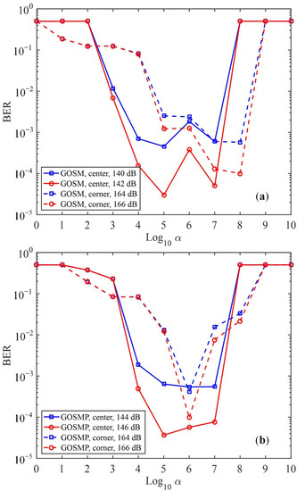
Figure 7.
BER vs. of the proposed CSI-free DNN detector for (a) GOSM and (b) GOSMP.
4.5. Computational Complexity
Finally, we evaluate the computational complexity of the proposed CSI-free DNN detector and compare it with other benchmark detectors. For both the CSI-free DNN detector and the ZF-DNN detector, once the detector has been successfully trained, it can be used for MIMO detection for a long period of time without further retraining, unless the system parameters such as receiver location have been changed [27]. Hence, only the computational complexity of the online detection process is considered for the CSI-free DNN detector and the ZF-DNN detector, whereas the complexity of the offline training process is not taken into account. Moreover, the computational complexity of the proposed DNN detectors and the other three benchmark detectors is evaluated and compared in terms of computation time, which is a common way for computational complexity evaluation in the literature [34]. Figure 8a,b compare the computation time of the proposed DNN detectors and the other three benchmark detectors for GOSM and GOSMP, respectively. As we can see, for GOSM, the CSI-free DNN detector, the ZF-DNN detector and the ZF-ML detector require nearly the same computation time which is less than 3 s. However, the joint ML detector requires totally 48.42 s to finish the computation, which is significantly longer than that of the other three detectors. It is the same for GOSMP that the CSI-free DNN detector, the ZF-DNN detector, and the ZF-ML detector require comparable computation time, which is much shorter than that required by the joint ML detector. Therefore, the proposed CSI-free DNN detector achieves near-optimal BER performance as the joint ML detector, but with substantially lower computational complexity.
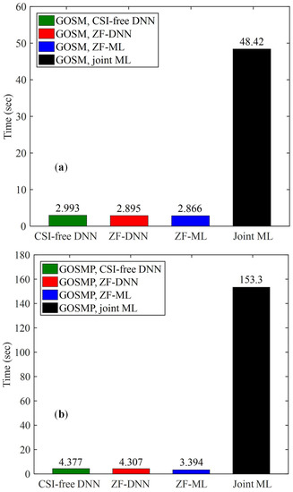
Figure 8.
Computation time comparison of the proposed CSI-free DNN detector and three benchmark detectors for (a) GOSM and (b) GOSMP at the center of the receiving plane.
5. Conclusions
In this paper, we have for the first time proposed a novel DeepGOMIMO framework for GOMIMO systems, where a DNN-based detector is specially designed to realize CSI-free detection of the received MIMO signals. The proposed CSI-free DNN detector contains a preprocessing module and a feedforward DNN module, which are used to address the adverse effects of MIMO transmission and to perform joint detection of spatial and constellation information, respectively. It is shown by our simulation results that, in a typical indoor 4 × 4 MIMO-OWC system adopting both GOSM and GOSMP with unipolar nonzero 4-PAM modulation, the CSI-free DNN detector achieves comparable BER performance as the optimal joint ML detector, which greatly outperforms the ZF-ML detector. Moreover, the CSI-free DNN detector, the ZF-DNN detector and the ZF-ML detector require nearly the same computation time to perform detection, which is significantly shorter than that required by the joint ML detector. In addition, compared with the ZF-DNN detector, the CSI-free DNN detector can achieve an improved achievable data rate and reduced communication time delay because it does not require instantaneous channel estimation to obtain accurate CSI for ZF equalization. In conclusion, our proposed DeepGOMIMO can be a potential candidate for the implementation of practical high-speed and low-complexity OWC systems.
Author Contributions
Formal analysis, C.C., Z.Z. and M.L.; funding acquisition, C.C.; investigation, X.Z. and S.F.; methodology, S.F.; project administration, C.C.; resources, Z.Z.; software, S.F.; supervision, C.C. and M.L.; validation, X.Z.; writing—original draft, X.Z.; writing—review & editing, C.C., S.F., Z.Z. and M.L. All authors have read and agreed to the published version of the manuscript.
Funding
This research was funded by the National Natural Science Foundation of China (62271091 and 61901065) and the Natural Science Foundation of Chongqing (cstc2021jcyj-msxmX0480).
Institutional Review Board Statement
Not applicable.
Informed Consent Statement
Not applicable.
Data Availability Statement
Not applicable.
Acknowledgments
The authors would like to thank the anonymous reviewers for their valuable comments and suggestions.
Conflicts of Interest
The authors declare no conflict of interest.
References
- Ghassemlooy, Z.; Arnon, S.; Uysal, M.; Xu, Z.; Cheng, J. Emerging optical wireless communications-advances and challenges. IEEE J. Sel. Areas Commun. 2015, 33, 1738–1749. [Google Scholar] [CrossRef]
- Cogalan, T.; Haas, H. Why would 5G need optical wireless communications? In Proceedings of the IEEE International Symposium on Personal, Indoor and Mobile Radio Communications, Montreal, QC, Canada, 8–13 October 2017; pp. 1–6. [Google Scholar]
- Chi, N.; Zhou, Y.; Wei, Y.; Hu, F. Visible light communication in 6G: Advances, challenges, and prospects. IEEE Veh. Technol. Mag. 2020, 15, 93–102. [Google Scholar] [CrossRef]
- Demirkol, I.; Camps-Mur, D.; Paradells, J.; Combalia, M.; Popoola, W.; Haas, H. Powering the Internet of Things through light communication. IEEE Commun. Mag. 2019, 57, 107–113. [Google Scholar] [CrossRef]
- Chen, C.; Fu, S.; Jian, X.; Liu, M.; Deng, X.; Ding, Z. NOMA for energy-efficient LiFi-enabled bidirectional IoT communication. IEEE Trans. Commun. 2021, 69, 1693–1706. [Google Scholar] [CrossRef]
- Le Minh, H.; O’Brien, D.; Faulkner, G.; Zeng, L.; Lee, K.; Jung, D.; Oh, Y.; Won, E.T. 100-Mb/s NRZ visible light communications using a postequalized white LED. IEEE Photonics Technol. Lett. 2009, 21, 1063–1065. [Google Scholar] [CrossRef]
- Zeng, L.; O’Brien, D.C.; Le Minh, H.; Faulkner, G.E.; Lee, K.; Jung, D.; Oh, Y.; Won, E.T. High data rate multiple input multiple output (MIMO) optical wireless communications using white LED lighting. IEEE J. Sel. Areas Commun. 2009, 27, 1654–1662. [Google Scholar] [CrossRef]
- Fath, T.; Haas, H. Performance comparison of MIMO techniques for optical wireless communications in indoor environments. IEEE Trans. Commun. 2013, 61, 733–742. [Google Scholar] [CrossRef]
- Chen, C.; Zhong, W.D.; Wu, D. On the coverage of multiple-input multiple-output visible light communications [Invited]. J. Opt. Commun. Netw. 2017, 9, D31–D41. [Google Scholar] [CrossRef]
- Chen, C.; Yang, H.; Du, P.; Zhong, W.D.; Alphones, A.; Yang, Y.; Deng, X. User-centric MIMO techniques for indoor visible light communication systems. IEEE Syst. J. 2020, 14, 3202–3213. [Google Scholar] [CrossRef]
- Mesleh, R.; Elgala, H.; Haas, H. Optical spatial modulation. J. Opt. Commun. Netw. 2011, 3, 234–244. [Google Scholar] [CrossRef]
- Alaka, S.; Narasimhan, T.L.; Chockalingam, A. Generalized spatial modulation in indoor wireless visible light communication. In Proceedings of the IEEE Global Communications Conference (GLOBECOM), San Diego, CA, USA, 6–10 December 2015; pp. 1–7. [Google Scholar]
- Wang, F.; Yang, F.; Song, J. Constellation optimization under the ergodic VLC channel based on generalized spatial modulation. Opt. Exp. 2020, 28, 21202–21209. [Google Scholar] [CrossRef] [PubMed]
- Wang, K. Indoor optical wireless communication system with filters-enhanced generalized spatial modulation and carrierless amplitude and phase (CAP) modulation. Opt. Lett. 2020, 45, 4980–4983. [Google Scholar] [CrossRef] [PubMed]
- Chen, C.; Zhong, X.; Fu, S.; Jian, X.; Liu, M.; Yang, H.; Alphones, A.; Fu, H.Y. OFDM-based generalized optical MIMO. J. Lightw. Technol. 2021, 39, 6063–6075. [Google Scholar] [CrossRef]
- Özbilgin, T.; Koca, M. Optical spatial modulation over atmospheric turbulence channels. J. Lightw. Technol. 2015, 33, 2313–2323. [Google Scholar] [CrossRef]
- LeCun, Y.; Bengio, Y.; Hinton, G. Deep learning. Nature 2015, 521, 436–444. [Google Scholar] [CrossRef]
- Wang, T.; Wen, C.K.; Wang, H.; Gao, F.; Jiang, T.; Jin, S. Deep learning for wireless physical layer: Opportunities and challenges. Chin. Commun. 2017, 14, 92–111. [Google Scholar] [CrossRef]
- Chen, X.; Li, B.; Proietti, R.; Liu, C.Y.; Zhu, Z.; Yoo, S.B. Demonstration of distributed collaborative learning with end-to-end QoT estimation in multi-domain elastic optical networks. Opt. Exp. 2019, 27, 35700–35709. [Google Scholar] [CrossRef]
- Vela, A.P.; Ruiz, M.; Fresi, F.; Sambo, N.; Cugini, F.; Meloni, G.; Potì, L.; Velasco, L.; Castoldi, P. BER degradation detection and failure identification in elastic optical networks. J. Lightw. Technol. 2017, 35, 4595–4604. [Google Scholar] [CrossRef]
- Rottondi, C.; Barletta, L.; Giusti, A.; Tornatore, M. Machine-learning method for quality of transmission prediction of unestablished lightpaths. J. Opt. Commun. Netw. 2018, 10, A286–A297. [Google Scholar] [CrossRef]
- Fan, Y.; Udalcovs, A.; Pang, X.; Natalino, C.; Furdek, M.; Popov, S.; Ozolins, O. Fast signal quality monitoring for coherent communications enabled by CNN-based EVM estimation. J. Opt. Commun. Netw. 2021, 13, B12–B20. [Google Scholar] [CrossRef]
- Peng, C.W.; Chan, D.W.; Tong, Y.; Chow, C.W.; Liu, Y.; Yeh, C.H.; Tsang, H.K. Long short-term memory neural network for mitigating transmission impairments of 160 Gbit/s PAM4 microring modulation. In Proceedings of the Optical Fiber Communication Conference (OFC), Optica Publishing Group, Washington, DC, USA, 6–11 June 2021. paper Tu5D.3. [Google Scholar]
- Lee, H.; Lee, I.; Quek, T.Q.; Lee, S.H. Binary signaling design for visible light communication: A deep learning framework. Opt. Exp. 2018, 26, 18131–18142. [Google Scholar] [CrossRef]
- Lu, X.; Lu, C.; Yu, W.; Qiao, L.; Liang, S.; Lau, A.P.T.; Chi, N. Memory-controlled deep LSTM neural network post-equalizer used in high-speed PAM VLC system. Opt. Exp. 2019, 27, 7822–7833. [Google Scholar] [CrossRef]
- Yang, H.; Alphones, A.; Zhong, W.D.; Chen, C.; Xie, X. Learning-based energy-efficient resource management by heterogeneous RF/VLC for ultra-reliable low-latency industrial IoT networks. IEEE Trans. Ind. Inform. 2019, 16, 5565–5576. [Google Scholar] [CrossRef]
- Wang, T.; Yang, F.; Song, J. Deep learning-based detection scheme for visible light communication with generalized spatial modulation. Opt. Exp. 2020, 28, 28906–28915. [Google Scholar] [CrossRef]
- Wang, Y.; Chi, N. Demonstration of high-speed 2 × 2 non-imaging MIMO Nyquist single carrier visible light communication with frequency domain equalization. J. Lightw. Technol. 2014, 32, 2087–2093. [Google Scholar] [CrossRef]
- Komine, T.; Nakagawa, M. Fundamental analysis for visible-light communication system using LED lights. IEEE Trans. Consum. Electron. 2004, 50, 100–107. [Google Scholar] [CrossRef]
- Tavakkolnia, I.; Yesilkaya, A.; Haas, H. OFDM-based spatial modulation for optical wireless communications. In Proceedings of the IEEE Globecom Workshops (GC Wkshps), Abu Dhabi, United Arab Emirates, 9–13 December 2018; pp. 1–6. [Google Scholar]
- Chen, C.; Zeng, L.; Zhong, X.; Fu, S.; Liu, M.; Du, P. Deep learning-aided OFDM-based generalized optical quadrature spatial modulation. IEEE Photonics J. 2022, 14, 7302306. [Google Scholar] [CrossRef]
- Zhong, X.; Chen, C.; Zeng, L.; Zhang, R.; Tang, Y.; Nie, Y.; Liu, M. Joint detection for generalized optical MIMO: A deep learning approach. In Proceedings of the IEEE Conference on Industrial Electronics and Applications (ICIEA), Chengdu, China, 1–4 August 2021; pp. 1317–1321. [Google Scholar]
- Ying, K.; Qian, H.; Baxley, R.J.; Yao, S. Joint optimization of precoder and equalizer in MIMO VLC systems. IEEE J. Sel. Areas Commun. 2015, 33, 1949–1958. [Google Scholar] [CrossRef]
- Albinsaid, H.; Singh, K.; Biswas, S.; Li, C.P.; Alouini, M.S. Block deep neural network-based signal detector for generalized spatial modulation. IEEE Commun. Lett. 2020, 24, 2775–2779. [Google Scholar] [CrossRef]
Publisher’s Note: MDPI stays neutral with regard to jurisdictional claims in published maps and institutional affiliations. |
© 2022 by the authors. Licensee MDPI, Basel, Switzerland. This article is an open access article distributed under the terms and conditions of the Creative Commons Attribution (CC BY) license (https://creativecommons.org/licenses/by/4.0/).