Communication

Directly Modulated Tunable Single-Mode Lasers Based on a Coupled Microcavity

1
Departamento de Eletrónica, Telecomunicações e Informática (DETI), Instituto de Telecomunicações, University of Aveiro, 3810-193 Aveiro, Portugal
2
Center of Materials Science and Optoelectronics Engineering, University of Chinese Academy of Sciences, Beijing 100049, China
3
State Key Laboratory of Integrated Optoelectronics, Institute of Semiconductors, Chinese Academy of Sciences, Beijing 100083, China
4
Shaoxing ZKTel Equipment Co., Ltd., Shaoxing 312000, China
*
Author to whom correspondence should be addressed.
Photonics 2022, 9(11), 827; https://doi.org/10.3390/photonics9110827
Submission received: 17 September 2022 / Revised: 20 October 2022 / Accepted: 2 November 2022 / Published: 4 November 2022
(This article belongs to the Special Issue Directly-Modulated Lasers)

Abstract

:
In this work, we investigate an alternative directly modulated laser solution with applications to multiwavelength 25 Gb/s systems. The presented solution is based on a hybrid square/rhombus-rectangular laser (HSRRL), which consists of a Fabry–Pérot (FP) cavity and a square/rhombus microcavity (SRM). This structure is implemented and demonstrates single-mode lasing over a wide wavelength tuning range (30.8 nm). Single-mode operation is achieved with a side-mode suppression ratio (SMSR) greater than 30 dB and a linewidth of 10 MHz. Furthermore, with an electrical 3 dB bandwidth of 10 GHz. It is possible to directly modulate at 25 Gb/s with promising performance. These devices are simple and they are expected to meet the cost and power requirements of current networks.

1. Introduction

In order to cope with the objectivated rates of 5G networks, the antenna coverage plan had to be revisited due to the required decrease in the coverage radius, which leads to the increase in the deployed number of antennas and base stations [1,2]. In order to realize a low-cost 5G any-haul, coarse wavelength division multiplexing (CWDM) industrial-grade 25 Gb/s several directly modulated DFB lasers were proposed [3,4]. Currently, 5G any-haul connections are based on 25 Gb/s direct modulated DFB lasers, mainly because direct modulated DFB lasers have the advantages of simple packaging and high power at low cost.
Tunable lasers are very important in the deployment of wavelength division multiplexing (WDM), which is the key technology for building next-generation optical networks. Researchers developed a variety of tunable semiconductor lasers with different structures, such as external cavity lasers (ECL) integrating diffraction gratings and micro-electro-mechanical systems (MEMS), which can achieve very narrow linewidth due to the good scalability of the external cavity length [5]. In addition, wavelength-tunable vertical cavity surface emitting lasers (VCSEL) using external cavity structures were also widely studied [6]. The current mainstream research focuses on monolithically integrated DFB laser arrays and DBR lasers [7,8,9]. The former integrates multiple DFB lasers with the same gain material in parallel, and the center wavelength of each laser is changed by adjusting the grating period, thereby achieving a wide range of wavelength tuning [10]. The latter mainly modulates the lasing wavelength by changing the refractive index of the grating part by current injection. Since the change in refractive index is very limited, the wavelength tuning range of conventional DBR lasers is small. Researchers also proposed a variety of improved DBR laser structures, including sampled grating DBR (SG-DBR) lasers [11,12], modulated grating Y-branch DBR (MGY-DBR) lasers [13], superstructure grating DBR (SSG-DBR) lasers [14], and chirped sampled grating DBR (CSG-DBR) lasers [15]. Silicon-based hybrid integrated tunable lasers [16], V-coupling cavity lasers [17], and tunable lasers based on surface etched slots [18] were proposed and studied, showing good tuning performance.
However, the development of novel lasers with lower cost or high-performance continued to be one of the goals pursued by researchers, as the recent example of the multichannel interference lasers [19,20] was reported in wavelength tuning range and SMSRs. A hybrid square-rectangular laser (HSRL) as a coupled cavity consisting of a square microcavity, and an FP cavity was demonstrated for mode Q factor control and single-mode operation [21,22,23]. Furthermore, a deformed HSRL with near-fundamental transverse mode distribution and improved far-field profiles in the FP cavity also shows good direct modulation characteristics and wavelength tunability [24].
In this work, we report a directly modulated (DM)-HSRRL composed of an SRM and an FP cavity, which shows single-mode operation with an SMSR over 30 dB. The wavelength tuning is achieved by varying injection currents of the SRM and FP cavity. The linewidth of the HSRRL is measured to be approximately 10 MHz. The direct modulation characteristics are investigated for the DM-HSRRL through the analysis of the eye-opening performance at 25 Gb/s. From the viewpoint of fabrication cost, the laser is based on generic InP-based quantum well platforms and standard photolithographic technique that are re-growth free and grating free, which represents a potential for a low-cost and compact single-mode tunable laser source.

2. Materials and Methods

The optically resonant cavity is formed by directly connecting a square/rhombus microcavity with a high-Q factor to an FP microcavity, whose structure is shown in Figure 1. A half square microcavity and a half rhombus form a WG mode microcavity, and the microcavity is angularly connected to an FP cavity. Among other characteristics, the WG mode has a large free spectral range due to its short optical path and operates single mode within a certain gain spectrum. As for the FP section, this has a small mode interval due to its generally long cavity length, and, for that reason, operates as a multi-mode for the same spectral range. These properties, together, result in a resonant enhancement that can be achieved when the resonance condition of both the square/rhombus microcavity and the FP cavity is satisfied. The lasing occurs in the FP facet. In addition, the square/rhombus microcavity can be regarded as an equivalent reflecting mirror with wavelength selective characteristics, forming a closed resonant circuit with the FP cavity. The corresponding wavelength of the WG mode can be adjusted by adjusting the refractive index of the square/rhombus microcavity, so that the WG mode can be coupled with different orders of FP modes to achieve a tunable output wavelength.
For the simulation of the resonator, a two-dimensional (2D) finite element method (FEM) (COMSOL Multiphysics 5.0) is utilized to calculate the mode reflectivity spectra of the microcavity. An HSRRL consists of an FP cavity with a width d, a length L, an SRM with a side length a, and a deformation amplitude δ. Here, the structure parameters are taken to be a = 15 μm, δ = 0.4 μm, d = 1.5 μm, and L = 300 μm, respectively, which are designed considering the single-mode lasing characteristics and Q factor [24].
The simulated boundary uses the perfectly matched layer (PML), and the dark blue and dark gray parts in Figure 1a represent the BCB region boundary and the air boundary, respectively. For the use of the PML layer, the influence of the simulation boundary reflection on the simulation results is avoided. In addition, the symmetry boundary condition (perfect magnetic conductor, PMC) is taken along the horizontal center dashed line to investigate the mode coupling between the fundamental FP transverse modes and WGMs. The coupled cavity has an effective refractive index (neff) of 3.2, is covered with 200 nm silicon nitride with a refractive index of 2, and the surrounding materials are bis-benzocyclobutene (BCB) and air with refractive indices of 1.54 and 1, respectively. The eigenfrequency calculation uses the physics interfaces electromagnetic waves, frequency domain, and the study “Eigenfrequency”. The calculation yields the complex frequency of the eigenfrequency, where the real part of freal represents the resonant frequency and the imaginary part of fimag represents the loss. The Q factors were calculated by Q = freal/fimag/2 for the entire HSRRL.
The model of reflection spectrum simulation is shown in Figure 1c,d. Set the scattering boundary condition (SBC) containing the plane wave at the end of the waveguide as the source, and set up a domain probe as the monitor in a section of the waveguide, record “Power outflow, time average” (“ewfd.nPoav”), and calculate the ewfd.nPoav connected to the PML (Figure 1d) and the WGM (Figure 1c), denoted as P1 and P2, respectively, then the reflectivity R = (P1 − P2)/P1.
The HSRRL does not have a distinct mirror between the two cavities, which may result in a self-consistent mode field pattern in the whole cavity. The square/rhombus microcavity as one side reflector of the FP cavity is numerically simulated, which shows high reflectivity around the instinct WGMs and reveals the possibility of realizing mode selection.
The fabrication processes of the HSRRLs are based on an AlGaInAs/InP laser wafer grown by metal–organic chemical vapor. The active region of the laser wafer consists of six compressively strained quantum wells, with 6 nm-thick Al0.24GaIn0.71As quantum wells and 9 nm-thick Al0.44GaIn0.49As barrier layers, confined by the lower cladding layers of 100 nm undoped graded AlGaInAs and 140 nm N-InAlAs, and upper cladding layers of 150 nm undoped graded AlGaInAs and InAlAs. The upper confinement layers are 1.6 μm InP and 0.2 μm P-InGaAs as a contacting layer. The N-doped density is about 1 × 1018 cm−3, and the P-doped densities increase from 5 × 1017 cm−3 to larger than 1 × 1019 cm−3 in the P-contacting layer. After growing a SiO2 layer, standard contact photolithography and inductively coupled plasma (ICP) etching techniques are used to transfer the coupled cavity patterns with a deep etching depth of about 4 μm. Then, the microcavity is confined by a 200 nm SiNx layer to protect the active region from being oxidized and a BCB cladding layer is coated to create a planar surface, followed by a large area of reactive ion etching to expose the top of coupled cavity resonators. To guarantee mutual electrical isolation, an isolation trench with a length of 20 μm is realized by another ICP etching technique to etch off the P-InGaAs ohmic contact layer between the rectangular and square/rhombus microcavity sections. After that, a patterned Ti/Pt/Au metal layer is evaporated as a top P-electrode using the lifting-off technique, and the substrate is mechanically lapped to a thickness of 120 μm with an Au-Ge-Ni metallization layer evaporated on the backside as the N-electrode [25]. Two patterned P-type electrodes are used for current injection into the SRM and the FP cavities separately. Finally, the wafer is packed in butterfly packaging with a fiber pigtail.

3. Simulation and Experimental Results

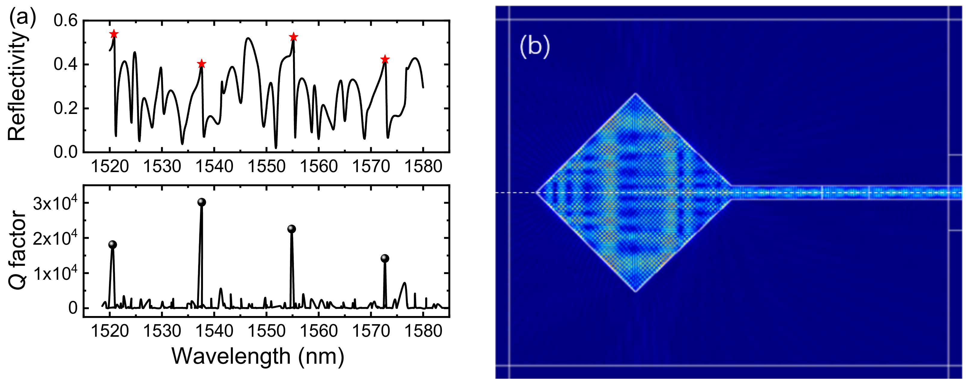
3.1. Simulation of Reflection and Mode Characteristics

Figure 1a shows the simulation of the reflection spectrum and Q factors of the HSRRL. An excitation source of the fundamental mode field is set at the light-emitting end face of the FP cavity, and the SRM part acts as a reflection end face to select the mode. It can be seen from Figure 2a that in the wavelength range of 1520–1580 nm, there are modes corresponding to four specific wavelengths (1520.8, 1537.6, 1555.2, and 1572.7 nm) with significantly higher reflectivity and narrower reflection peak widths, indicating that these modes also have high-Q. The mode field distribution is shown in Figure 1b, which means that the higher-order modes in the SRM are more easily coupled with the modes in the FP cavity. The mode field and its Q factor distribution of this HSRRL structure using the same geometric model is simulated. The results indicate that there are four groups of high-Q modes, corresponding to wavelengths of 1520.5, 1537.6, 1554.8, and 1572.6 nm, respectively. The longitudinal mode spacing is about 17 nm, which is in good agreement with the wavelengths of the four high-reflectivity modes on the reflectance spectrum, and they also have similar mode field distributions, which is similar to the field distribution pattern of the excited modes with high reflectivity in Figure 2b. In addition, some broad-spectrum high reflection peaks on the reflection spectrum will not be lasing in practice because their Q factors are too low. This structure is beneficial to the realization of very good single-mode lasing in the actual fabricated device.

3.2. Static Characteristics of the Implemented Microlasers

The lasing wavelength of the HSRRL is tuned by changing the carrier concentration, and thus the refractive index, through current injection. The output light of the laser is connected to a power meter for recording power, to an optical spectrum analyzer (OSA) for recording spectrum, and a self-homodyne optical coherent receiver system for linewidth testing. The operating temperature of the laser is controlled by a thermoelectric cooler (TEC) at 290 K.
Single-mode fiber (SMF) coupled power versus the injection current of FP cavity IFP at an injection current of SRM ISRM fixed at 5, 10, 20, and 30 mA are measured and plotted in Figure 3a for the HSRRL. The threshold current is about 18 mA under ISMR = 5 mA and the resistance between the SRM and the FP cavity is about 10.3 kΩ. The maximum power coupled to SMF is about 5 mW. The slope efficiencies are estimated to be about 0.06 and 0.13 W/A before the thermal saturation for the HSRRLs with ISRM of 5 and 30 mA, respectively. The black curve corresponds to the FP cavity current–voltage curve when ISRM is fixed at 10 mA and the matching resistor of 35 Ω is added to the circuit to ensure 50 Ω impedance matching in high-speed test systems. The device exhibits good single-mode lasing when the current of the SRM cavity is fixed at 10 mA independently of the current of the FP cavity. Figure 3b shows the entire lasing spectra. The FSR of the FP cavity is 0.89 nm in Figure 3b, which correspond to an effective FP cavity length of 375 nm, with a group refractive index of 3.6. Due to the extra optical path provided by the SRM, the effective FP cavity length is longer than the actual FP cavity. In fact, when the current of the square cavity is fixed at other values, the output spectrum of the laser is similar.

3.3. Lorentzian Linewidth and Wavelength Tuning of HSRRL

Figure 4a shows the detailed lasing spectrum of the HSRRL with an ISRM of 51 mA and IFP of 40 mA. The SMSR reaches 46 dB, indicating that the HSRRL has excellent single-mode characteristics with good suppression of other mode peaks. The corresponding FM noise spectrum curve measured by the self-homodyne optical coherent receiver method was obtained through data analysis in Figure 4b, where the white noise region is in the frequency range from 20 MHz to 100 MHz. According to the relationship between Lorentzian linewidth and white noise, the linewidths corresponding to the wavelength of 1565.2 nm are calculated to be 3.72 MHz [26]. We also performed a detailed characterization on the HSRRL and obtained the linewidth of about 10 MHz for the 1560 nm wavelength and less than 15 MHz in the entire tuning range, as shown in Figure 5.
We characterized the wavelength of the electrically tuned HSRRL. IFP was fixed at 40 mA during the characterization process and ISRM was tuned. The results are shown in Figure 5a, where the superimposed lasing spectra of different excitation wavelengths are presented from 1545.9 to 1576.8 nm, representing a tuning range of 30.8 nm. In Figure 5b, the SMSRs and the Lorentzian linewidths of all lasing wavelengths are more than 30 dB in the whole tuning range, except for the wavelength of 1561.6 nm. We also performed a detailed characterization of the HSRRL and obtained the Lorentzian linewidths of all lasing wavelengths about 10 MHz and less than 15 MHz in the entire tuning range, as shown in Figure 5b.

3.4. Small-Signal Electrical Modulation Response

The small-signal electrical modulation responses are plotted in Figure 6a for the HSRRL at the biasing currents IFP of 20, 25, 30, 60, and 75 mA and biasing current ISRM of 20 mA, which was conducted using a 20 GHz bandwidth network analyzer. The 3 dB bandwidths are 3.5, 7.6, and 10.2 GHz at the bias currents of 20, 30, and 60 mA, respectively. Relaxation resonance frequencies fR extracted from the small-signal modulation response curves versus the square root of the bias current minus the threshold current, is shown in Figure 6b. The D factor is 1.65 GHz/mA1/2, which is a quality factor used to evaluate how efficiently an intrinsic laser could be modulated [27], and the modulation current efficiency factor (MCEF) is obtained of 2.22 GHz/mA1/2. Fitting by the following linear relation: γ = K·fR2 + γ0, the K-factor describes the damping of the response, and as such, is an important parameter in the characterization of high-speed lasers. Here, K = 0.16 GHz−1 is obtained, which means the modulation bandwidth for low damping, as well as the maximum possible bandwidth of 55.5 GHz.

3.5. Large-Signal Modulation Results

Finally, the eye diagram measurement using a high-speed photodetector with 70 GHz bandwidth and a 90 GHz digital sampling oscilloscope at 10 and 25 Gbit/s are tested and presented in Figure 7 for back-to-back (BTB) configuration with a nonreturn-to-zero (NRZ) pseudo-random binary sequence (PRBS) of 231 - 1 input into the FP cavity. The lasing wavelength is 1546.1 nm and the bias currents were 60 mA for the FP cavity and 20 mA for the SRM, and the modulation voltage was 1.5 V peak-to-peak. Extinction ratios of 3.47 and 2.34 dB are obtained for the eye diagram of 10 and 25 Gbit/s.

4. Discussion and Improvement Paths

The implemented DM-HSRRL exhibits good lasing characteristics such as the high SMSR in the entire wavelength tuning range except at the wavelength of 1561.6 nm, which is at the switching position of the two longitudinal modes of the HSRRL. The heat generated by the current applied at this time is very high for the former longitudinal mode, thus causing the performance of the device to deteriorate. In addition, we tested the Lorentzian linewidth over the entire wavelength tuning range. Due to the influence of the environment, the coupling output power of the laser in the SMF will fluctuate randomly during the test, which causes the linewidth value obtained by our test to fluctuate greatly under some currents. These problems can be improved by encapsulating the device and improving the cooling effect of the TEC.
The modulation bandwidth could be greatly improved by optimizing the mode Q factor and reflectivity for HSRRLs. An excessively high cavity Q factor for passive microresonators would result in a degenerated modulation speed due to the prolonged turn-on delay, while low mode Q factor and high internal absorption loss could also cause a high resonance peak in the small-signal response curve, which will also deteriorate the quality of the eye diagrams [28].
Recently, China Unicom’s 25 Gbps wavelength-based tunable optical module adaptive access DWDM system industry chain gradually matured and released the G.698.4 standard, which operates the wavelength in C-band, mainly used in long-distance transmission, such as the WDM system, generally uses an electro-absorption modulated laser (EML) or extra-modulator before transmission to 10 km at a 25 Gbps rate and 80 km at a 10 Gbps rate. In this work, a low-cost novel structured configuration of the tunable laser is realized for 25 Gbps data transmission. In general, 5G forward lasers use O-band wavelengths for the reason that the 10–15 km transmission can be achieved without EML lasers because of the small dispersion. Further research will use this structure to study the O-band direct modulation semiconductor lasers to save cost.

5. Conclusions

A hybrid square/rhombus-rectangular laser (HSRRL) is demonstrated for single-mode operation with SMSR higher than 30 dB in a wavelength tuning range of 30.8 nm by adjusting the injection currents of the SRM and the FP cavity simultaneously. The laser linewidth is about 10 MHz and the SMF coupled power is over 5 mW. Furthermore, 3 dB modulation bandwidth of 10 GHz and an open-eye diagram at 25 Gb/s are demonstrated for the HSRRLs. The directly modulated HSRRLs are promising to meet the cost and power requirements of current access networks.

Author Contributions

Conceptualization, Y.-Z.H. (Yong-Zhen Huang), Y.-D.Y. and J.-L.X.; methodology, Y.-Z.H. (Yong-Zhen Huang), Y.-D.Y. and A.L.T.; software, M.-Q.W., B.Z., Y.-Z.H. (You-Zeng Hao) and Z.-N.Z.; validation, M.-Q.W. and Y.-Z.H. (You-Zeng Hao); formal analysis, Y.-Z.H. (You-Zeng Hao); investigation, M.-Q.W. and Y.-Z.H. (You-Zeng Hao); resources, J.-L.X., Z.-N.Z. and Y.-Z.H. (You-Zeng Hao); data curation, Z.-N.Z. and Y.-Z.H. (You-Zeng Hao); writing—original draft preparation, M.-Q.W. and J.-L.X.; writing—review and editing, J.-L.X. and Y.-Z.H. (Yong-Zhen Huang); visualization, M.-Q.W., Y.-Z.H. (You-Zeng Hao) and Z.-N.Z.; supervision, Y.-Z.H. (Yong-Zhen Huang) and J.-L.X.; project administration, J.-L.X. and Y.-Z.H. (Yong-Zhen Huang). All authors have read and agreed to the published version of the manuscript.

Funding

This research was funded by Strategic Priority Research Program, Chinese Academy of Sciences, grant number XDB43000000.

Institutional Review Board Statement

Not applicable.

Informed Consent Statement

Not applicable.

Data Availability Statement

Not applicable.

Acknowledgments

We thank the discussions of eye diagrams measurement with Zhi Liu and Yu Peng Zhu at Institute of Semiconductors, Chinese Academy of Sciences.

Conflicts of Interest

The authors declare no conflict of interest.

References

  1. Ji, Y.; Zhang, J. 5G optical fronthaul: Key issues, features and goals. Sci. Sin. Inf. 2017, 47, 1435–1442. [Google Scholar]
  2. Zhang, M. Flex Ethernet Technology and Application in 5G Mobile Transport Network. China Commun. 2021, 18, 250–258. [Google Scholar] [CrossRef]
  3. Xu, R.; Deng, C.S. New protection solution in native passive O-band CWDM for 5G front-haul. Telecom Eng. Tech. Stand. 2019, 32, 680–686. [Google Scholar]
  4. Zhang, H.; Huang, W.P. Product definition and enabling technologies for 5G wireless transceiver. ZTE Technol. J. 2018, 24, 51–53. [Google Scholar]
  5. Chen, B.; Meinertzhagen, I.A.; Shaw, S.R. Circadian rhythms in light-evoked responses of the fly’s compound eye, and the effects of neuromodulators 5-HT and the peptide PDF. J. Comp. Physiol. A 1999, 185, 393–404. [Google Scholar] [CrossRef]
  6. Cole, G.D.; Bjorlin, E.S.; Qi, C.; Chung-Yeung, C.; Shaomin, W.; Wang, C.S.; MacDonald, N.C.; Bowers, J.E. MEMS-tunable vertical-cavity SOAs. IEEE J. Quantum Electron. 2005, 41, 390–407. [Google Scholar] [CrossRef] [Green Version]
  7. Ishii, H.; Kasaya, K.; Oohashi, H.; Shibata, Y.; Yasaka, H.; Okamoto, K. Widely wavelength-tunable DFB laser array integrated with funnel combiner. IEEE J. Sel. Top. Quantum Electron. 2007, 13, 1089–1094. [Google Scholar] [CrossRef]
  8. Hatakeyama, H.; Naniwae, K.; Kudo, K.; Suzuki, N.; Sudo, A.; Ae, S.; Muroya, Y.; Yashiki, K.; Satoh, K.; Morimoto, T.; et al. Wavelength-selectable microarray light sources for S-, C-, and L-band WDM systems. IEEE Photonics Technol. Lett. 2003, 15, 903–905. [Google Scholar] [CrossRef]
  9. Suematsu, Y.; Kishino, K.; Arai, S.; Koyama, F. Dynamic Single-Mode Semiconductor-Lasers with a Distributed Reflector. Semicond. Semimet 1985, 22, 205–255. [Google Scholar] [CrossRef]
  10. Ishii, H.; Kasaya, K.; Oohashi, H. Spectral Linewidth Reduction in Widely Wavelength Tunable DFB Laser Array. IEEE J. Sel. Top. Quantum Electron. 2009, 15, 514–520. [Google Scholar] [CrossRef]
  11. Jayaraman, V.; Chuang, Z.M.; Coldren, L.A. Theory, Design, and Performance of Extended Tuning Range Semiconductor-Lasers with Sampled Gratings. IEEE J. Quantum Electron. 1993, 29, 1824–1834. [Google Scholar] [CrossRef]
  12. Sassi, R.; Bond, R.R.; Cairns, A.; Finlay, D.D.; Guldenring, D.; Libretti, G.; Isola, L.; Vaglio, M.; Poeta, R.; Campana, M.; et al. PDF-ECG in clinical practice: A model for long-term preservation of digital 12-lead ECG data. J. Electrocardiol. 2017, 50, 776–780. [Google Scholar] [CrossRef]
  13. Muller, M.S.; Hoffmann, L.; Bodendorfer, T.; Hirth, F.; Petit, F.; Plattner, M.P.; Buck, T.C.; Koch, A.W. Fiber-Optic Sensor Interrogation Based on a Widely Tunable Monolithic Laser Diode. IEEE Trans. Instrum. Meas. 2010, 59, 696–703. [Google Scholar] [CrossRef]
  14. Fujiwara, M.; Sasaki, M. Photon number resolving detector at telecom wavelengths: Charge integration photon detector (CIPD). IEEE J. Sel. Top. Quantum Electron. 2007, 13, 952–958. [Google Scholar] [CrossRef]
  15. Srivastava, A.K.; Weiershausen, W.; Dingel, B.B.; Dutta, A.K.; Kaneko, T.; Matsuura, H.; Tanizawa, K.; Uesaka, K. High-power and narrow-linewidth tunable distributed-reflector laser. In Proceedings of the Optical Metro Networks and Short-Haul Systems VIII, San Francisco, CA, USA, 16–18 February 2016. [Google Scholar]
  16. Nemoto, K.; Kita, T.; Yamada, H. Narrow-Spectral-Linewidth Wavelength-Tunable Laser Diode with Si Wire Waveguide Ring Resonators. Appl. Phys. Express 2012, 5, 8. [Google Scholar] [CrossRef]
  17. Meng, J.; Xiong, X.; Xing, H.; Jin, H.; Zhong, D.; Zou, L.; Zhao, J.; He, J.J. Full C-Band Tunable V-Cavity-Laser Based TOSA and SFP Transceiver Modules. IEEE Photonics Technol. Lett. 2017, 29, 1035–1038. [Google Scholar] [CrossRef]
  18. Nawrocka, M.; Lu, Q.; Guo, W.H.; Abdullaev, A.; Bello, F.; O’Callaghan, J.; Cathcart, T.; Donegan, J.F. Widely tunable six-section semiconductor laser based on etched slots. Opt. Express 2014, 22, 18949–18957. [Google Scholar] [CrossRef]
  19. Chen, Q.; Jiang, C.; Wang, K.; Zhang, M.; Ma, X.; Liu, Y.; Lu, Q.; Guo, W. Narrow-linewidth thermally tuned multi-channel interference widely tunable semiconductor laser with thermal tuning power below 50  mW. Photon. Res. 2020, 8, 671–676. [Google Scholar] [CrossRef]
  20. Jiang, C.; Chen, Q.; Wang, K.; Lu, Q.; Lu, M.; Guo, W. Narrow-linewidth thermally tuned multi-channel interference laser integrated with a SOA and spot size converter. Opt. Express 2021, 29, 13246–13255. [Google Scholar] [CrossRef]
  21. Ma, X.W.; Huang, Y.Z.; Yang, Y.D.; Xiao, J.L.; Weng, H.Z.; Xiao, Z.X. Mode coupling in hybrid square-rectangular lasers for single mode operation. Appl. Phys. Lett. 2016, 109, 071102. [Google Scholar] [CrossRef]
  22. Ma, X.W.; Huang, Y.Z.; Yang, Y.D.; Weng, H.Z.; Xiao, J.L.; Tang, M.; Du, Y. Mode and Lasing Characteristics for Hybrid Square-Rectangular Lasers. IEEE J. Sel. Top. Quantum Electron. 2017, 23, 1500409. [Google Scholar] [CrossRef]
  23. Wang, F.L.; Ma, X.W.; Huang, Y.Z.; Yang, Y.D.; Han, J.Y.; Xiao, J.L. Relative intensity noise in high-speed hybrid square-rectangular lasers. Photon. Res. 2018, 6, 193–197. [Google Scholar] [CrossRef] [Green Version]
  24. Hao, Y.Z.; Wang, F.L.; Tang, M.; Weng, H.Z.; Yang, Y.D.; Xiao, J.L.; Huang, Y.Z. Widely tunable single-mode lasers based on a hybrid square/rhombus-rectangular microcavity. Photonics Res. 2019, 7, 543–548. [Google Scholar] [CrossRef]
  25. Yang, Y.D.; Xiao, J.L.; Liu, B.W.; Huang, Y.Z. Mode characteristics and vertical radiation loss for AlGaInAs/InP microcylinder lasers. J. Opt. Soc. Am. B 2015, 32, 439–444. [Google Scholar] [CrossRef]
  26. Tran, M.A.; Huang, D.; Bowers, J.E. Tutorial on narrow linewidth tunable semiconductor lasers using Si/III-V heterogeneous integration. APL Photonics 2019, 4, 111101. [Google Scholar] [CrossRef] [Green Version]
  27. Westbergh, P.; Gustavsson, J.S.; Kogel, B.; Haglund, A.; Larsson, A. Impact of Photon Lifetime on High-Speed VCSEL Performance. IEEE J. Sel. Top. Quantum Electron. 2011, 17, 1603–1613. [Google Scholar] [CrossRef]
  28. Lv, X.-M.; Huang, Y.-Z.; Zou, L.-X.; Long, H.; Du, Y. Optimization of direct modulation rate for circular microlasers by adjusting mode Q factor. Laser Photon. Rev. 2013, 7, 818–829. [Google Scholar] [CrossRef]
Figure 1. (a) Diagram of the model used for the simulation of the Q value for the coupled-cavity laser composed of an FP cavity and an SRM as a deformed square microcavity with a vertex extending a distance of δ. (b) Microscope image of the fabricated HSRRL. (c,d) Diagrams for simulating the reflection spectrum of the SRM cavity as a reflective end face in the coupled-cavity laser.
Photonics 09 00827 g001
Figure 2. (a) The reflection spectrum and quality factors (Q) of HSRRL, and (b) mode intensity profiles of Hz at 1537.6 nm.
Photonics 09 00827 g002
Figure 3. (a) The voltage and SMF coupled power versus FP cavity CW injection current with fixed SRM currents of 5, 10, 20, and 30 mA, respectively. (b) The lasing spectra when the SRM injection current is fixed at 10 mA and FP cavity injection current versus from 10 mA to 120 mA.
Photonics 09 00827 g003
Figure 4. (a) The lasing spectrum of HSRRLs at injection currents of ISRM = 51 mA and IFP = 40 mA. (b) FM noise spectrum curve of 1565.2 nm wavelength.
Photonics 09 00827 g004
Figure 5. (a) Superimposed lasing spectra for HSRRLs and (b) the SMSR and linewidth in the entire tuning wavelength range.
Photonics 09 00827 g005
Figure 6. (a) Small-signal modulation responses of the HSRRL at the FP cavity biasing currents of 20, 25, 30, 60, and 75 mA and SRM biasing current of 20 mA. (b) The fitted relaxation resonance frequencies fR and 3 dB bandwidths versus the square root of the bias current minus the threshold current.
Photonics 09 00827 g006
Figure 7. Eye diagrams at the modulation bit rates of 10 and 25 Gbit/s for HSRRL.
Photonics 09 00827 g007
Publisher’s Note: MDPI stays neutral with regard to jurisdictional claims in published maps and institutional affiliations.

