Communication

Experimental Study on 25 Gbps C-Band PON over up to 25 km SMF Using a 10G-Class DML + APD IM-DD System

Department of Electronics and Telecommunications, Politecnico di Torino, Corsso Duca degli Abruzzi 24, 10129 Torino, Italy
*
Author to whom correspondence should be addressed.
Photonics 2021, 8(8), 328; https://doi.org/10.3390/photonics8080328
Submission received: 5 July 2021 / Revised: 1 August 2021 / Accepted: 6 August 2021 / Published: 11 August 2021
(This article belongs to the Special Issue Directly-Modulated Lasers)

Abstract

:
In this paper we present an experimental analysis of several modulation formats (pulse amplitude modulation (PAM-2), quaternary pulse amplitude modulation (PAM-4) and electrical duobinary (EDB)) for passive optical network (PON) applications at 25 Gbps bit rate in a C-band 10G-class directly modulated lasers (DML) and avalanche photodiode (APD) intensity modulation and direct detection (IM-DD) system over a single mode fiber (SMF) of up to 25 km, optimizing DML operations and demonstrating that PAM-2 is a promising choice. We also theoretically and experimentally analyzed the channel frequency response of DML and SMF affected by DML chirp and SMF chromatic dispersion.

1. Introduction

The time division multiplexed (TDM) passive optical network (PON) has been one of the most important architectures to support the increasing bandwidth and traffic requirements in access networks. The standardization of 25 Gb/s per λ (25G-PON) has been recently released by IEEE (25G-EPON [1]). Standardization of 50 Gbps PONs is under development by IEEE and ITU-T. 50Gbps PONs exploit two wavelengths per direction, each at 25 Gbps [2,3]. The 25G-PON physical layer will preserve the intensity modulation and direct detection (IM-DD) scheme to allow low-cost transmitter (TX) and receiver (RX) optics. For the first time in a PON standardization release, both the uplink and downlink will operate in O-band (around 1300 nm) to cope with chromatic dispersion over the PON standard reach from 0 to (at least) 20 km over single-mode fiber (SMF) [1,2,3,4,5,6,7,8].
Our group has analyzed in previous papers the performance of directly modulated laser (DML)-based IM-DD PON systems in O-band [9,10,11]. In [12,13], the channel frequency response of a DML-based IM-DD system was investigated in O-band through simulations and theoretical calculations. In general, DML represents a good choice when it operates in a system with low chromatic dispersion (CD), for example, in O-band, because of the low cost and small footprint advantages [14,15,16], while, because of laser chirp effects, it is usually less suitable for C-band operation. However, it was shown in [17] that DML, when operated in some specific situations, can even achieve a better performance than electro-absorption modulated laser (EML) and Mach–Zehnder modulator (MZM) in C-band, since under proper combination of adiabatic and nonadiabatic chirp, DML can give a higher nonfaded bandwidth than EML and MZM. The modulation bandwidth of DML is generally smaller and the chirp is generally higher than those of external modulators. External modulators, therefore, are more suited to higher data rate and longer reaches transmission (i.e., >10 km) [18]. However, DML is better suited to optical access networks, such as PON, due to low cost, low power consumption, low insertion loss, compactness, and high optical output power [19,20]. The bandwidth of commercial DMLs can currently reach 21 GHz [21]. A 65 GHz bandwidth low chirp (enhancement linewidth factor α < 1.0) DML module was demonstrated in [22], in which a high data rate transmission of 294.7 Gbps over 15 km single mode fiber (SMF) was achieved without using complex high speed electronic compensations, a strong optical confinement effect, or optical fiber amplifiers. Moreover, 100 Gb/s commercial DML has yet to be released [23].
Regarding modulation formats for 25 and 50 Gbps PON, besides traditional binary NRZ (return-to-zero, and possibly in a duobinary version), two other modulation formats, quaternary pulse amplitude modulation (PAM-4) and duobinary PAM-4 (DB-PAM-4) have been studied in the literature. When using DML lasers, the key physical layer impairments are well known to be the mix of laser chirp, fiber chromatic dispersion, and the limitations in the available modulation bandwidth. For instance, in [24], the measured channel frequency response of a DML based IM-DD system over a 0–20 km SMF and the measured receiver sensitivity of an on–off keying (OOK) signal obtained at low extinction ratio (ER) (below 2.7 dB) were shown. Typically, at bit rates above 10 Gbps for PON applications, chromatic dispersion (CD) may have an important impact, and this is the reason why, as mentioned before, both 25G- and 50G-PON currently under proposal in the ITU-T and IEEE standardization bodies operate in the O-band (around 1300 nm), where CD is at its minimum.
Compared to O-band, there are two main advantages of C-band: lower optical loss and lower optical nonlinearity (because CD is not zero at 1550 nm; on the contrary, CD equals to zero at 1300 nm in O-band). Moreover, both downstream and upstream transmission in both 25G- and 50G-PON standardizations currently operate in O-band. Therefore, in future PON standardization, it may happen that the O-band window is full, so that it may become of interest to move again to the C-band. This is the rationale behind our paper. In fact, it is necessary to study DML based IM-DD systems in C-band 1550 nm. In the IM-DD system in [17], the eye skewing effect caused by adiabatic chirp and higher CD in the C-band mentioned before is mitigated by the intensity directed equalizer. Apart from IM-DD PON systems, several studies have been carried out in C-band. To overcome the higher CD in C-band, single sideband (SSB) modulation has been proposed in fiber-wireless systems [25] and radio-over-fiber links [26], and the tunable dispersion compensation module (TDCM) has been proposed in 5G networks [27]. In the high bit rate PON channel, severe optoelectronic (O/E) bandwidth (BW) limitations and power fading due to CD are two of the main issues [28]. The main limitation of the DML based IM-DD system (compared to EML and MZM based systems) is the interaction induced by CD and the adiabatic chirp of DML, which is a nonlinear impairment, in general complex to be analyzed. Frequency fluctuations in the transmitted signal (i.e., chirp) due to the higher dispersion in C-band over the link can generate intersymbol interference (ISI) at receiver [29]. The chirp of DML therefore limits the maximum transmission distance. As discussed in [17], directly modulated PAM symbols have different optical frequencies due to different intensity levels. The resulting eye skewing effect and other nonlinear distortions are caused when PAM modulated signals are transmitted over high dispersion links in C-band. Therefore, the ISI of adjacent symbols is different for the different intensity levels of PAM symbols. A fiber with negative dispersion was designed in [30] to gain from the positive chirp of DML. In [31], a tunable optical filter (TOF) was designed to reduce the impairments. RX offline digital signal processing (DSP), e.g., feed forward equalization (FFE) and decision feedback equalization (DFE), can be used to partially overcome the impairments.
In this paper, we experimentally analyzed three problems: (1) the E/O frequency response of the 10G-class DML, (2) the frequency response of the DML based IM-DD system over a 25–118 km SMF, and (3) the maximum ODN loss (max. ODN loss) that can be achieved using this system employing electrical duobinary (EDB), NRZ-OOK (also termed as pulse amplitude modulation (PAM-2)), and PAM-4 signals as a function of extinction ratio (in a range from about 1 to 9 dB) at 25 Gbps over an SMF of up to 25 km in C-band using direct detection. We considered feed-forward equalization (FFE) and decision feedback equalization (DFE) approaches at the receiver, which were performed by using the offline processing approach in our laboratory experiments. We experimentally obtained that PAM-2 should be the the most appropriate modulation format of 25G-PON.
The paper is organized in the following way: details of the experimental setup are described in Section 2. The experimental results are reported in Section 3. In Section 3.1, the E/O frequency response of our 10 G-class DML is characterized. In Section 3.2, we experimentally and theoretically analyze the channel frequency response of SMF in a DML based IM-DD system. In Section 3.3, we compare the performance of EDB, PAM-2, and PAM-4 signals as a function of ER. We conclude in Section 4.

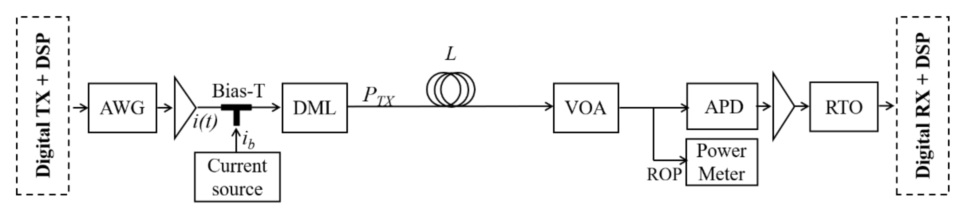
2. Experimental Setup

The experimental setup is schematically illustrated in Figure 1. At the TX side, EDB, PAM-2, or PAM-4 optical modulation was generated using PRBS random sequences at bit rate Rb = 25 Gbps by an offline digital TX and digital signal processing (DSP) block, which is described in detail in [10]. Here we briefly mention that for PAM-2 and PAM-4 options were generated in a standard way, while for EDB the following setup was used: a 2-level pre-coded signal was generated at TX. It was precoded by using a standard XOR-and-delay-based block. At RX, the received signal was detected by using a duobinary equalizer-based receiver. A 3-level signal was used as a training sequence for adaptive equalization (AEQ).
The resulting offline TX block generated signal was converted into an analog electrical signal i(t) by a Keysight © (Santa Rosa, CA, USA) 92 GSa/s arbitrary waveform generator (AWG). We could change the DML’s resulting output ER by changing the peak-to-peak voltage, which is a parameter could be set in the AWG. After the amplification, a DC-bias was added to the signal by a Bias-T. The bias current of the laser ib was varied to optimize the performance. Then, the experimental setup drove a 1550 nm C-band 10G-class Gooch and Housego © DML (Ilminster, UK). The transmitted optical power was set as PTX = 8.5 dBm. The resulting modulated optical signal was propagated over a conventional SMF with length L = 20 km or 25 km. The received optical power (ROP) was measured by a power meter after a variable optical attenuator (VOA). At the RX side, the signal was received by a 10G-class avalanche photodiode (APD) followed by an electrical amplifier and a 100 GSa/s sampling rate Tektronix © (Beaverton, OR, USA) real time oscilloscope (RTO). In the offline Digital RX + DSP block, we proposed two solutions: (a) an FFE with a number of taps Ntaps = 20 (we termed this as “FFE”) and (b) an FFE with Ntaps = 20 followed by a DFE with Ntaps = 5 (we termed this as “FFE + DFE”) to partially compensate for linear and nonlinear impairments.
As performance metrics, we used the required ROP (RROP) at bit error rate (BER) target of BERT = 10−2; the resulting ODN loss, defined as the difference in dB between the transmitted optical power PTX and the received one (i.e., ODN loss, dB = PTX − ROP, both in dBm); and the maximum ODN loss (max. ODN loss, dB = PTX − RROP, both in dBm). This is the typical metric used in the PON environment, since PON standards are very demanding in terms of ODN loss.

3. Experimental Results

In this section, we present our main experimental results. Different bias currents of the DML ib and different fiber lengths L were used to experimentally analyze the overall electrical-to-electrical frequency response of the experimental DML based IM-DD system with SMF fiber. Then, we show the performance of three modulation formats, i.e., EDB, PAM-2, and PAM-4, which were compared by employing two solutions, i.e., FFE and FFE + DFE.

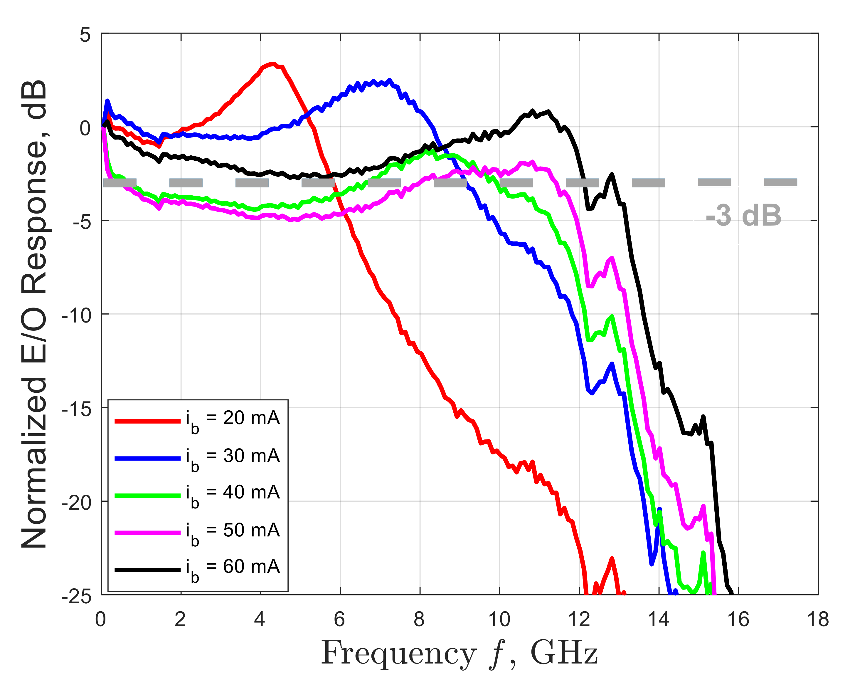
3.1. Measured E/O Response of the 10G-Class DML

We start by showing the measured back-to-back (B2B) response of 10G-class 1550 nm DML. The results are shown in Figure 2 to characterize the DML used in this experiment. The measured frequency response was normalized to |HDML(f = 0)|. The frequency responses were measured by using an optical network analyzer (ONA) connected directly to the DML. As shown in the figure, the measured 3 dB bandwidth of the 10G-class DML was about 4.5 GHz, 8 GHz, 10 GHz, 12 GHz, and 12.5 GHz for the values of DML input bias current ib = 20 mA, 30 mA, 40 mA, 50 mA, and 60 mA, respectively. In the datasheet of our DML [32], an S21 frequency response characterization of the device is shown. However, it is not specified at which bias current ib this measurement was performed. From our measurements, a similar frequency response as that reported in the datasheet was obtained at 60 mA. When observing Figure 2, please note the DML BW strong dependency versus the DML bias current ib. The BW is positively correlated to ib when ib is below the suggested maximum ib (100 mA, which is indicated in the datasheet [32]). We experimentally demonstrated that ib = 60 mA keeps the operation of the DML on the safe side as well as guaranteeing optimum performance [10]. Therefore, we will only use ib = 60 mA in the rest of the paper.

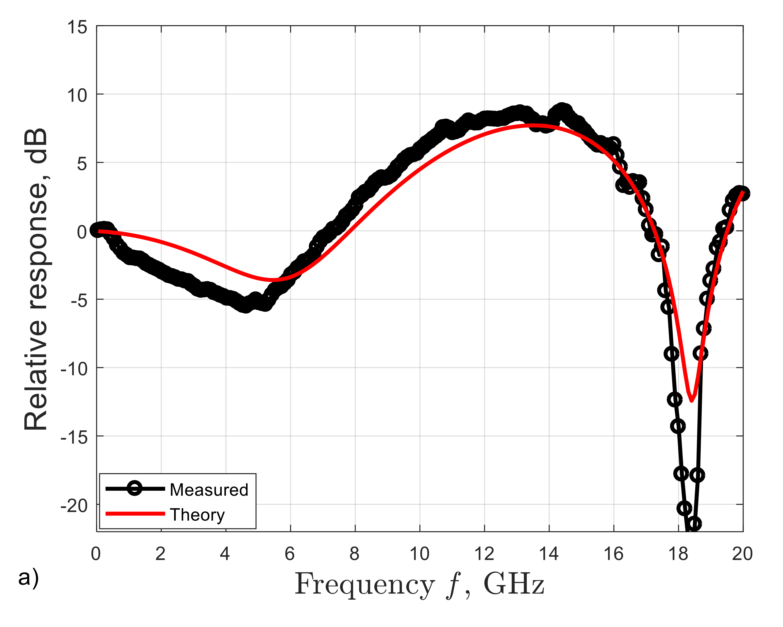
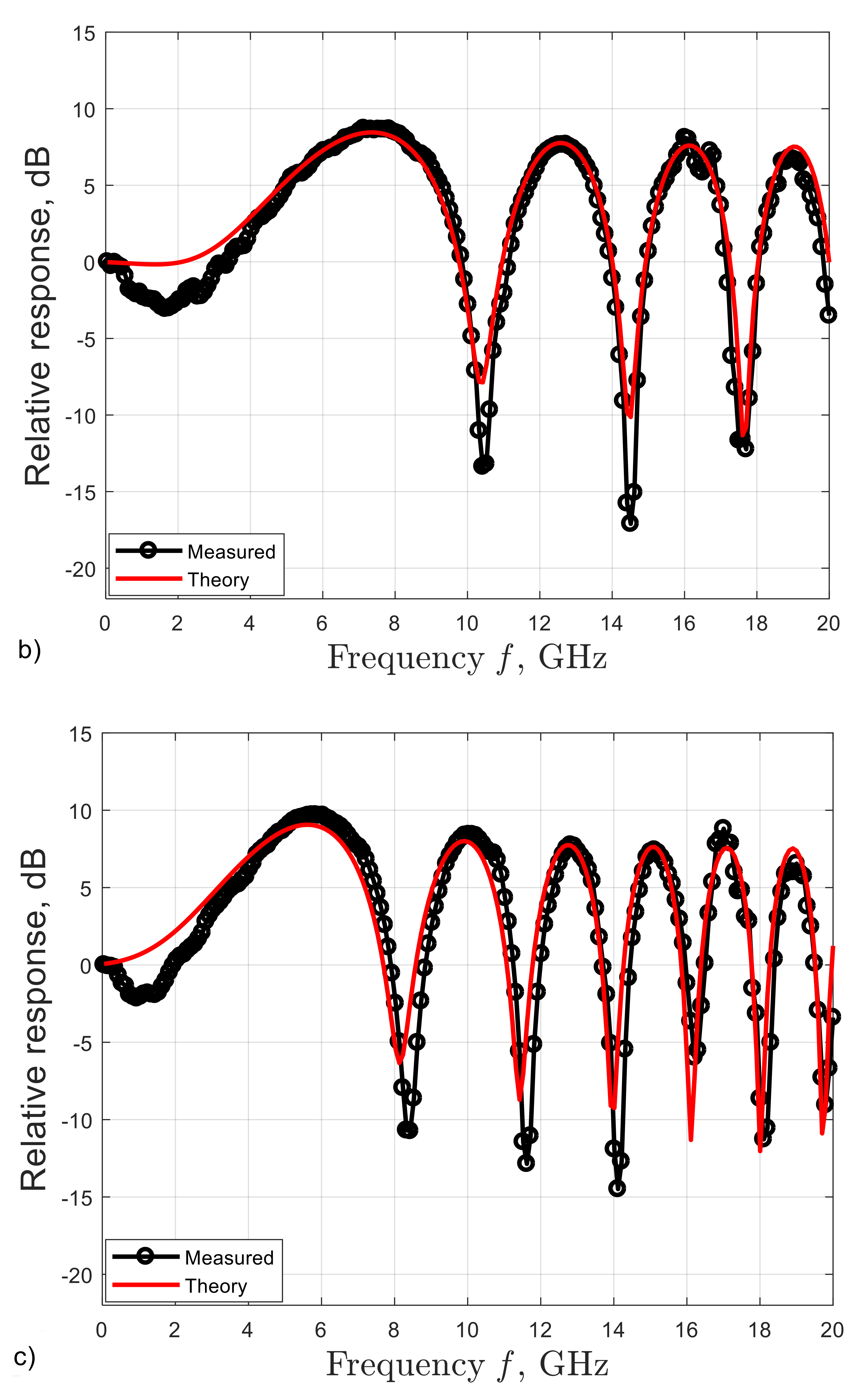
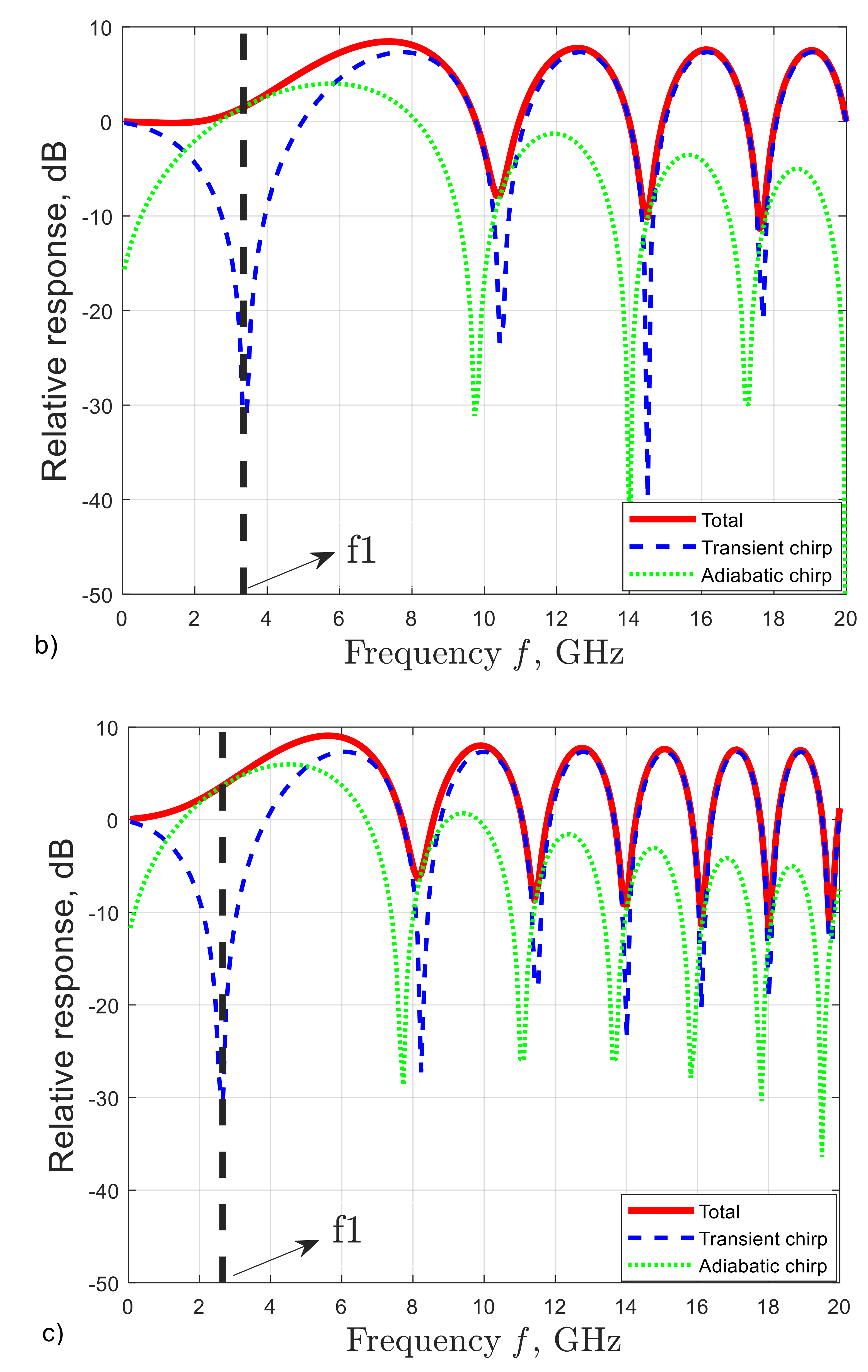
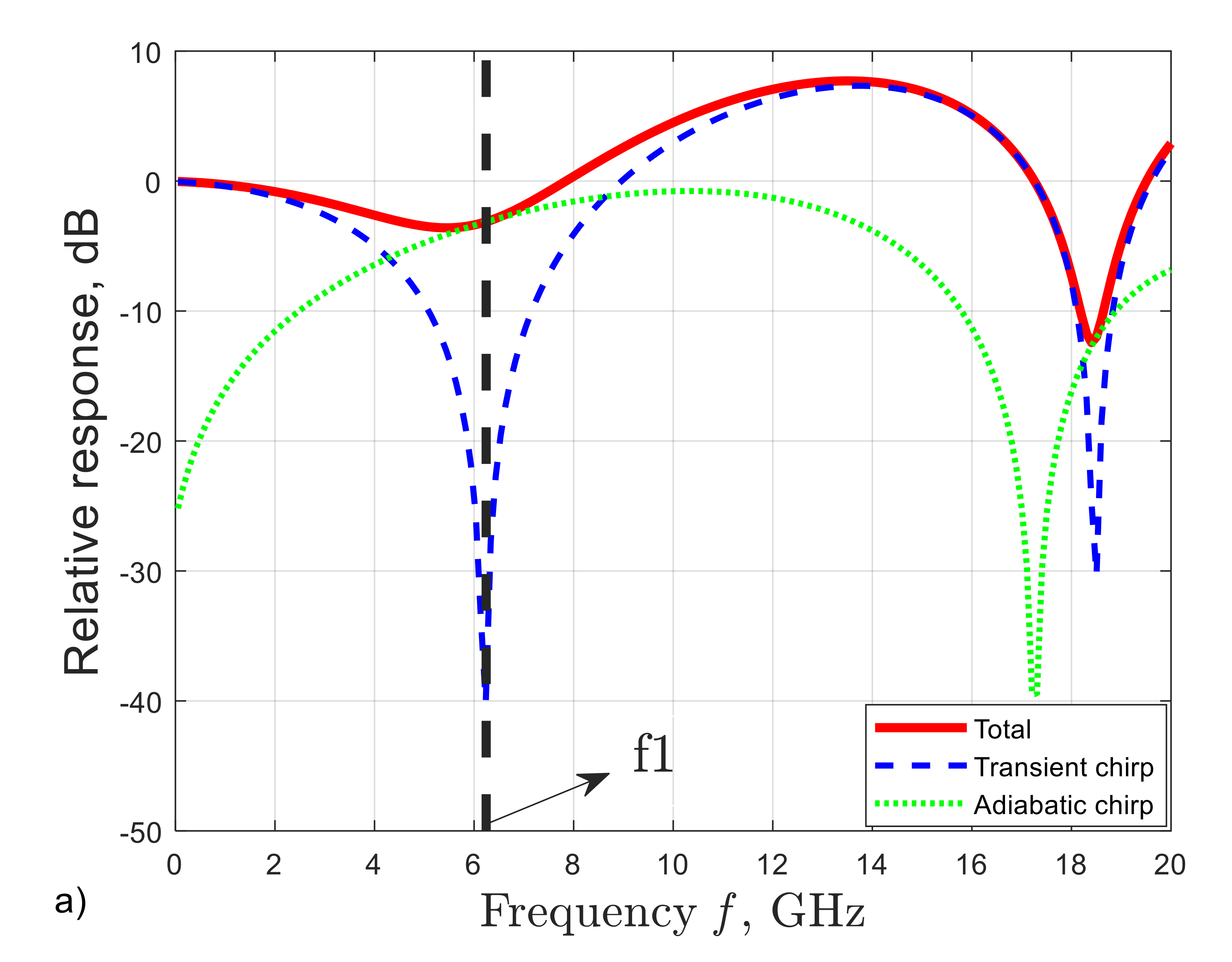
3.2. Frequency Fiber Channel Response Analysis

We continue by analyzing the measured frequency response after different lengths of SMF. The frequency responses were measured by again using the ONA. The frequency responses shown in Figure 3 were obtained by extracting the frequency response measured in Figure 2 with ib = 60 mA, i.e., with 0 km fiber, to show the overall frequency response including SMF and DML chirp effects. The channel frequency response of SMF in a DML based IM-DD system can be theoretically evaluated using Equation (1) [33,34]:
H ω = α + 1 c o s θ + t a n 1 α + j α κ P 0 ω s i n θ
where α is the enhancement linewidth factor, κ is the adiabatic chirp factor (the DML chirp parameters), P0 in W is the average output power of the DML (i.e., PTX), ω = 2Пf (where f is the frequency in Hz), θ = Dλ2ω2L/4Пc (where λ is the wavelength of the signal in m), D is the CD parameter in s/m2, L is the fiber length in m, and c in m/s is the speed of light in vacuum. The black solid lines with circles show the measured frequency responses. On top of the experimental graph, the red lines specify the theoretical responses by using Equation (1), obtained after a fitting procedure on the free parameters [35]. Please note that the DML parameters α and κ are not normally available on the DML datasheet, so we used simulations and experimental measurements to evaluate them. In the fitting procedure, α, κ and D were set as three free parameters. After the fitting procedure, we obtained α = 2.1, κ = 3.3 GHz/mW, and D = 16.64 ps/(nm·km) (which were obtained from fitting procedure performed in this section) as well as P0 = 8.5 dBm (which Was measured at the output of the DML by using an optical power meter). The measured frequency responses are remarkably consistent with the theoretical ones calculated by using Equation (1) for all three different fiber lengths L = 25 km, 75 km, and 118 km. As shown in Figure 3, we can observe several frequency notches. For instance, as shown in Figure 3b, the three frequency notches are at around 10 GHz, 14 GHz, and 18 GHz.
In Equation (1), the first and second terms are caused by the transient chirp and adiabatic chirp of the DML, respectively. In Figure 4, we present the total frequency responses (extracted from the theoretical response in Figure 3) with different fiber lengths. The total frequency response can be decomposed into transient chirp and adiabatic chirp. From the ideas of [24], we can observe that the first notch induced by the transient chirp (in blue dashed curves) can be partially compensated by the adiabatic chirp (in green solid curves). As a result, at the frequency f1 (where first notch induced by the transient chirp appears), the total frequency response (in red solid line) does not suffer the notch at frequency f1. However, the notches induced by the transient chirp appearing after frequency f1 cannot be compensated by the adiabatic chirp, since the notches induced by the transient and adiabatic chirp appear at almost the same frequency. Therefore, we can observe 1, 3, and 6 notch(es) with 25 km, 75 km, and 118 km fiber respectively (within the measurable frequency window). From Equation (1), the bandwidth of SMF in a DML based IM-DD system can be expressed in Equation (2) [24]:
BW     c D λ 2 L
The first frequency notches for L = 25 km, 75 km, and 118 km are at around 18 GHz, 10 GHz, and 8 GHz respectively. These values are consistent with the values calculated by using the Equation (2). The bandwidth of SMF in the DML based IM-DD system is more dependent on the frequency of the first notch of the adiabatic chirp, since the first notch of the transient chirp is compensated by the adiabatic one.

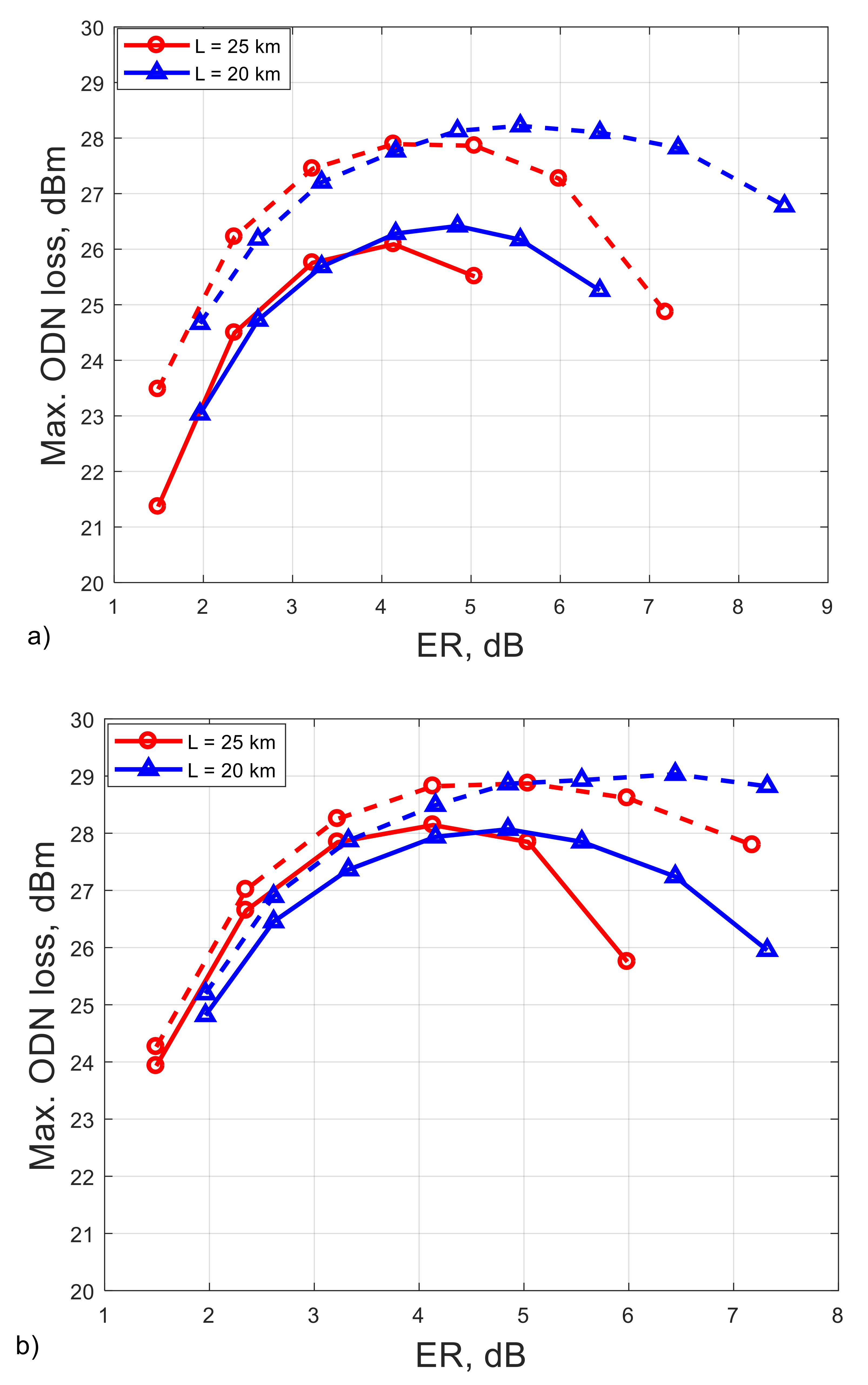
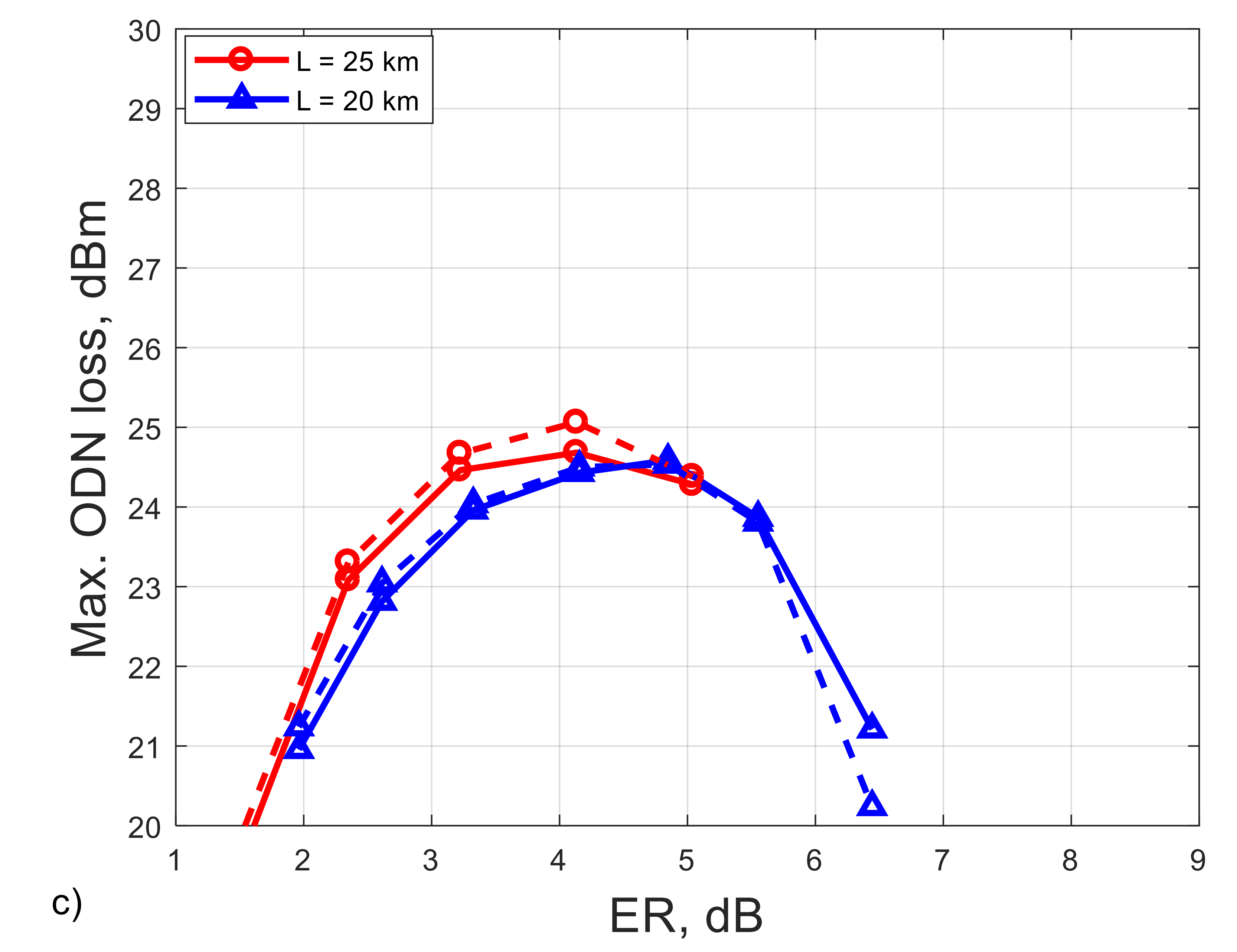
3.3. System Performance

In Figure 5, we investigate the system performance for three modulation formats and two different types of equalization in terms of max. ODN loss as a function of ER set at DML side. Note the DML bias current ib = 60 mA to keep the DML operating on the safe side as well as at the optimum performance. As shown in Figure 5, the optimum ER is about 4 dB for all modulation formats. The performance in terms of max. ODN loss with 20 km fiber is very similar to that with 25 km fiber. From Section 3.2, the bandwidth of SMF (including DML chirp effects) based on IM-DD systems is about 18 GHz with 25 km fiber, and from Equation (2) we can observe that this bandwidth limitation is irrelevant if compared with DML and APD bandwidths. Therefore, the bandwidth of this DML based IM-DD link is more limited by the bandwidth of DML (from Figure 2: 12 GHz at ib = 60 mA) and APD bandwidth. The 3-dB bandwidth of our APD is around 7 GHz [36]; the overall system is therefore mainly limited by the APD. Comparing the performance of FFE and FFE + DFE, for EDB and PAM-4, the improvement is very limited by applying FFE + DFE. PAM-2 is the only one among these three modulation formats that has a relatively large enhancement (in terms of the max. ODN loss, an enhancement of about 2 dB) when the FFE + DFE is applied. EDB and PAM-2 have the same baud rate, but the spectrum bandwidth of EDB is only the half of that of PAM-2. The spectrum bandwidths of PAM-4 and EDB are narrower than that of PAM-2. As shown in Figure 3a, in the frequency response of a 25 km SFM in a DML based IM-DD system, an overshooting can be observed from around 6 GHz to 16 GHz. This can help to compensate partially the low-pass attenuation when DML and APD are applied alone (i.e., the back-to-back case), and the overall BW of the system is increased as a result. PAM-2 outperformed EDB when the bandwidth limitation was relaxed. Therefore, in Figure 5, PAM-2 shows the best performance among these three modulation formats. On the other hand, the overshoot is not observed in O-band which has much lower CD. We have experimentally demonstrated in [10] that EDB is the best among these three modulation formats in O-band 25G-PON because of the more limited bandwidth. The performance of PAM-2 + FFE is very similar to that of EDB + FFE + DFE, and FFE is less complex than FFE + DFE. Moreover, in terms of max. ODN loss, PAM-2 + FFE + DFE is the only scenario where it can reach 29 dB, which is the typical required power budget for 25G-PON [5]. Therefore, PAM-2 represents a good choice for DML based 25G-PON in C-band.

4. Discussion and Conclusions

We experimentally demonstrated 25 Gbps transmission over an up to 25 km SMF in a 10G-class DML based IM-DD system in C-band. We performed the characterization of our 10G-class DML in terms of measured frequency response at different bias current ib. ib = 60 mA was selected to ensure the optimum performance of the DML. In [12,13], the channel frequency response of a DML-based IM-DD system was analyzed in O-band through only simulations and theoretical calculations. We analyzed in detail the measured frequency response of different lengths up to 118 km SMF in a DML based IM-DD system in C-band following the ideas from [24]. The theoretical frequency response and measured ones matched well. From the matching procedure we obtained the laser chirp parameters α and κ. We also discussed the decomposition of the frequency response. We theoretically showed that the bandwidth of the DML based IM-DD over SMF system is depends mainly on the frequency of the first notch of the adiabatic chirp. Finally, we experimentally demonstrated that PAM-2 is a promising choice for 25G-PON if operation in C-band is the target, because in combination with DFE it provides the maximum admissible ODN loss among other options and can reach the typical required power budget for 25G-PON (29 dB). Moreover, since the 25G- and 50G-PON standards currently both operate in O-band both in the downstream and upstream directions, very likely, the O-band window well be fully occupied in the future. Then, C-band will be available, representing a good choice to move some services of 25G-PON. Moreover, the fiber losses and the impact of fiber nonlinearities are lower in C-band.

Author Contributions

Conceptualization, R.G., V.F., P.T.-F. and H.W.; methodology, R.G., V.F., P.T.-F., and H.W.; software, H.W.; validation, R.G., V.F., P.T.-F. and H.W.; formal analysis, R.G., V.F., P.T.-F. and H.W.; investigation, R.G., V.F., P.T.-F. and H.W.; resources, R.G., V.F., P.T.-F. and H.W.; data curation, P.T.-F. and H.W.; writing—original draft preparation, H.W.; writing—review and editing, R.G., V.F., P.T.-F. and H.W.; visualization, R.G., V.F., P.T.-F. and H.W.; supervision, R.G., and V.F.; project administration, R.G., and V.F. All authors have read and agreed to the published version of the manuscript.

Funding

The research received no external funding.

Institutional Review Board Statement

Not applicable.

Informed Consent Statement

Not applicable.

Data Availability Statement

Not applicable.

Acknowledgments

We thank the support of the PhotoNext initiative at Politecnico di Torino. This work was carried out in the framework of a research contract with Telecom Italia Lab (the TIM company research laboratory).

Conflicts of Interest

The authors declare no conflict of interest.

References

  1. IEEE. IEEE Standard for Ethernet Amendment 9: Physical Layer Specifications and Management Parameters for 25 Gb/s and 50 Gb/s Passive Optical Networks. In IEEE Std 802.3ca-2020; IEEE: Piscataway, NJ, USA, 2020; pp. 1–267. [Google Scholar]
  2. Zhang, D.; Liu, D.; Wu, X.; Nesset, D. Progress of ITU-T higher speed passive optical network (50G-PON) standardization. J. Opt. Commun. Netw. 2020, 12, D99–D108. [Google Scholar] [CrossRef]
  3. Harstead, E.; van Veen, D.; Houtsma, V.; Dom, P. Technology Roadmap for Time-Division Multiplexed Passive Optical (TDM PONs). J. Light. Technol. 2019, 37, 657–664. [Google Scholar] [CrossRef]
  4. The International Telecommunication Union (ITU). G.9804.1. Higher Speed PON Requirements. 2011. Available online: https://www.itu.int/itu-t/recommendations/rec.aspx?rec=14024 (accessed on 21 June 2021).
  5. Houtsma, V.; Van Veen, D.; Harstead, E. Recent Progress on Standardization of Next-Generation 25, 50, and 100G EPON. J. Light. Technol. 2016, 35, 1228–1234. [Google Scholar] [CrossRef]
  6. Harstead, E.; Bonk, R.; Walklin, S.; Van Veen, D.; Houtsma, V.; Kaneda, N.; Mahadevan, A.; Borkowski, R. From 25 Gb/s to 50 Gb/s TDM PON: Transceiver architectures, their performance, standardization aspects, and cost modeling. J. Opt. Commun. Netw. 2020, 12, D17. [Google Scholar] [CrossRef]
  7. White Paper on 50G-PON Technology. Available online: https://res-www.zte.com.cn/mediares/zte/Files/PDF/white_book/White_Paper_on_50G-PON_Technology_20201210_EN.pdf?la=en (accessed on 21 June 2021).
  8. Houtsma, V.; Mahadevan, A.; Kaneda, N.; Van Veen, D. Transceiver technologies for passive optical networks: Past, present, and future [Invited Tutorial]. J. Opt. Commun. Netw. 2020, 13, A44. [Google Scholar] [CrossRef]
  9. Torres-Ferrera, P.; Wang, H.; Ferrero, V.; Pagano, A.; Valvo, M.; Mercinelli, R.; Gaudino, R. Field demonstration of 25G-PON and XGS-PON burst-mode upstream coexistence. In Proceedings of the 45th European Conference on Optical Communication (ECOC 2019), Dublin, Ireland, 22–26 September 2019; pp. 1–4. [Google Scholar] [CrossRef]
  10. Torres-Ferrera, P.; Wang, H.; Ferrero, V.; Valvo, M.; Gaudino, R. Optimization of Band-Limited DSP-Aided 25 and 50 Gb/s PON Using 10G-Class DML and APD. J. Light. Technol. 2019, 38, 608–618. [Google Scholar] [CrossRef]
  11. Wang, H.; Torres-Ferrera, P.; Ferrero, V.; Pagano, A.; Mercinelli, R.; Gaudino, R. Current Trends towards PON systems at 50+ Gbps. In Proceedings of the 2020 Italian Conference on Optics and Photonics (ICOP), Parma, Italy, 9–11 September 2020; pp. 1–4. [Google Scholar] [CrossRef]
  12. Neto, L.A.; Maes, J.; Larsson-Edefors, P.; Nakagawa, J.; Onohara, K.; Trowbridge, S.J. Considerations on the Use of Digital Signal Processing in Future Optical Access Networks. J. Light. Technol. 2019, 38, 598–607. [Google Scholar] [CrossRef]
  13. Xue, L.; Yi, L.; Hu, W.; Lin, R.; Chen, J. Optics-Simplified DSP for 50 Gb/s PON Downstream Transmission using 10 Gb/s Optical Devices. J. Light. Technol. 2019, 38, 583–589. [Google Scholar] [CrossRef]
  14. Gao, F.; Zhou, S.; Li, X.; Fu, S.; Deng, L.; Tang, M.; Liu, D.; Yang, Q. 2 × 64 Gb/s PAM-4 trans-mission over 70 km SSMF using O-band 18G-class directly modulated lasers (DMLs). Opt. Express 2017, 25, 7230–7237. [Google Scholar] [CrossRef]
  15. Zhang, K.; Zhuge, Q.; Xin, H.; Xing, Z.; Xiang, M.; Fan, S.; Yi, L.; Hu, W.; Plant, D.V. Demonstration of 50Gb/s/λ Symmetric PAM4 TDM-PON with 10G-class Optics and DSP-free ONUs in the O-band. In Proceedings of the 2018 Optical Fiber Communications Conference and Exposition (OFC), San Diego, CA, USA, 11–15 March 2018; pp. 1–3. [Google Scholar] [CrossRef]
  16. Gao, Y.; Cartledge, J.C.; Yam, S.S.; Rezania, A.; Matsui, Y. 112 Gb/s PAM-4 Using a Directly Modulated Laser with Lin-ear Pre-Compensation and Nonlinear Post-Compensation. In Proceedings of the 42nd European Conference on Optical Communication, Düsseldorf, Germany, 18–22 September 2016; pp. 1–3. [Google Scholar]
  17. Zhang, K.; Zhuge, Q.; Xin, H.; Hu, W.; Plant, D.V. Performance comparison of DML, EML and MZM in dispersion-unmanaged short reach transmissions with digital signal processing. Opt. Express 2018, 26, 34288–34304. [Google Scholar] [CrossRef] [PubMed]
  18. Zhu, N.H.; Shi, Z.; Zhang, Z.K.; Zhang, Y.M.; Zou, C.W.; Zhao, Z.P.; Liu, Y.; Li, W.; Li, M. Directly Modulated Semiconductor Lasers. IEEE J. Sel. Top. Quantum Electron. 2017, 24, 1–19. [Google Scholar] [CrossRef]
  19. Bi, M.; Xiao, S.; Yi, L.; He, H.; Li, J.; Yang, X.; Hu, W. Power budget improvement of symmetric 40-Gb/s DML-based TWDM-PON system. Opt. Express 2014, 22, 6925–6933. [Google Scholar] [CrossRef]
  20. Che, D.; Matsui, Y.; Schatz, R.; Raybon, G.; Bhatt, V.; Kwakernaak, M.; Sudo, T. Long-Term Reliable >200-Gb/s Directly Modulated Lasers with 800GbE-Compliant DSP. In Proceedings of the 2021 Optical Fiber Communications Conference and Exhibition (OFC), San Francisco, CA, USA, 6–10 June 2021; pp. 1–3. [Google Scholar]
  21. Datasheet of “II-VⅠ 1300 nm 28 Gb/s NRZ DFB Laser Diode Chips”. Available online: https://ii-vi.com/product/28-gbaud-dfb-laser-diode-chip/ (accessed on 31 July 2021).
  22. Matsui, Y.; Schatz, R.; Che, D.; Khan, F.; Kwakernaak, M.; Sudo, T. Low-chirp isolator-free 65-GHz-bandwidth directly modulated lasers. Nat. Photon. 2020, 15, 59–63. [Google Scholar] [CrossRef]
  23. Sudo, T.; Matsui, Y.; Carey, G.; Verma, A.; Wang, D.; Lowalekar, V.; Kwakernaak, M.; Khan, F.; Dalida, N.; Patel, R.; et al. Challenges and Opportunities of Directly Modulated Lasers in Future Data Center and 5G Networks. In Proceedings of the 2021 Optical Fiber Communications Conference and Exhibition (OFC), San Francisco, CA, USA, 6–10 June 2021; pp. 1–3. [Google Scholar]
  24. Bae, S.H.; Kim, H.; Chung, Y.C. Transmission of 51.56-Gb/s OOK signal using 1.55-μm directly modulated laser and duobinary electrical equalizer. Opt. Express 2016, 24, 22555–22562. [Google Scholar] [CrossRef] [PubMed]
  25. Smith, G.H.; Novak, D.; Ahmed, Z. Overcoming chromatic-dispersion effects in fiber-wireless systems incorporating external modulators. IEEE Trans. Microw. Theory Tech. 1997, 45, 1410–1415. [Google Scholar] [CrossRef]
  26. Won, P.C.; Zhang, W.; Williams, J.R. Self-Phase Modulation Dependent Dispersion Mitigation in High Power SSB and DSB + Dispersion Compensated Modulated Radio-over-Fiber Links. In Proceedings of the 2006 IEEE MTT-S International Microwave Symposium Digest, San Francisco, CA, USA, 11–16 June 2006; pp. 1947–1950. [Google Scholar] [CrossRef]
  27. Ilgaz, M.; Baliz, K.V.; Batagelj, B. A Flexible Approach to Combating Chromatic Dispersion in a Centralized 5G Network. Opto-Electron. Rev. 2020, 28, 35–42. [Google Scholar]
  28. Zhang, Z.; Guo, Q.; Ju, C.; Cai, S.; Wang, L.; Zhang, M.; Chen, X. Optical- and Electrical-Domain Compensation Techniques for Next-Generation Passive Optical Networks. IEEE Commun. Mag. 2019, 57, 144–150. [Google Scholar] [CrossRef]
  29. Hinton, K.; Stephens, T. Modeling high-speed optical transmission systems. IEEE J. Sel. Areas Commun. 1993, 11, 380–392. [Google Scholar] [CrossRef]
  30. Tomkos, I.; Hallock, B.; Roudas, I.; Hesse, R.; Boskovic, A.; Vodhanel, R.; Nakano, J. Transmission of 1550 nm 10Gb/s di-rectly modulated signal over 100km of negative dispersion fiber without any dispersion compensation. In Proceedings of the Optical Fiber Communication Conference and International Conference on Quantum Information, Anaheim, CA, USA, 17–22 March 2001. [Google Scholar]
  31. Yi, L.; Li, Z.; Bi, M.; Wei, W.; Hu, W. Symmetric 40-Gb/s TWDM-PON with 39-dB Power Budget. IEEE Photon. Technol. Lett. 2013, 25, 644–647. [Google Scholar] [CrossRef] [Green Version]
  32. Datasheet of “Gooch & Housego© HIGH BANDWIDTH DFB LASER, 7-pin k-package, AA0701 Series”. Available online: https://gandh.com/wp-content/uploads/2017/02/GH_DS_FO_HighBandwidthDFBLaser_AA0701_7038_Rev05-1.pdf (accessed on 22 June 2021).
  33. Bjerkan, L.; Røyset, A.; Hafskjaer, L.; Myhre, D. Measurement of laser parameters for simulation of high-speed fiberoptic systems. J. Light. Technol. 1996, 14, 839–850. [Google Scholar] [CrossRef]
  34. Peral, E.; Yariv, A.; Marshall, W.K. Precise measurement of semiconductor laser chirp using effect of propagation in dispersive fiber and application to simulation of transmission through fiber gratings. J. Light. Technol. 1998, 16, 1874–1880. [Google Scholar] [CrossRef] [Green Version]
  35. Devaux, F.; Sorel, Y.; Kerdiles, J. Simple measurement of fiber dispersion and of chirp parameter of intensity modulated light emitter. J. Light. Technol. 1993, 11, 1937–1940. [Google Scholar] [CrossRef]
  36. Discovery Semiconductors Inc. 10 Gb/s APD+TIA Optical Receiver with Optional CDR, DSC-R402APD Model. Available online: https://www.discoverysemi.com/Product_Pages/DSCR402APD.php (accessed on 22 June 2021).
Figure 1. Experimental setup.
Photonics 08 00328 g001
Figure 2. Measured E/O response of the 10G-class DML with different bias currents of the DML ib in C-band (1550 nm).
Photonics 08 00328 g002
Figure 3. Frequency response of SMFs with different fiber length L in C-band (1550 nm) and with bias current of the DML ib = 60 mA. Solid line and circle: measured response. Solid line: theoretical response obtained by using Equation (1). (a) L = 25 km, (b) L = 75 km, and (c) L = 118 km.
Photonics 08 00328 g003aPhotonics 08 00328 g003b
Figure 4. Decomposition of frequency response (transient chirp and adiabatic chirp) of SMFs with different fiber lengths L. (a) L = 25 km, (b) L = 75 km, and (c) L = 118 km.
Photonics 08 00328 g004aPhotonics 08 00328 g004b
Figure 5. Maximum ODN loss as a function of ER over 20 km or 25 km SMF in C-band (1550 nm) and with bias current of the DML ib = 60 mA. Solid: FFE; dashed: FFE + DFE. (a) EDB, (b) PAM-2, and (c) PAM-4.
Photonics 08 00328 g005aPhotonics 08 00328 g005b
Publisher’s Note: MDPI stays neutral with regard to jurisdictional claims in published maps and institutional affiliations.

