Compressing High Energy Lasers through Optical Polymer Films

 , ,
, ,  , , , ,
Abstract
:1. Introduction
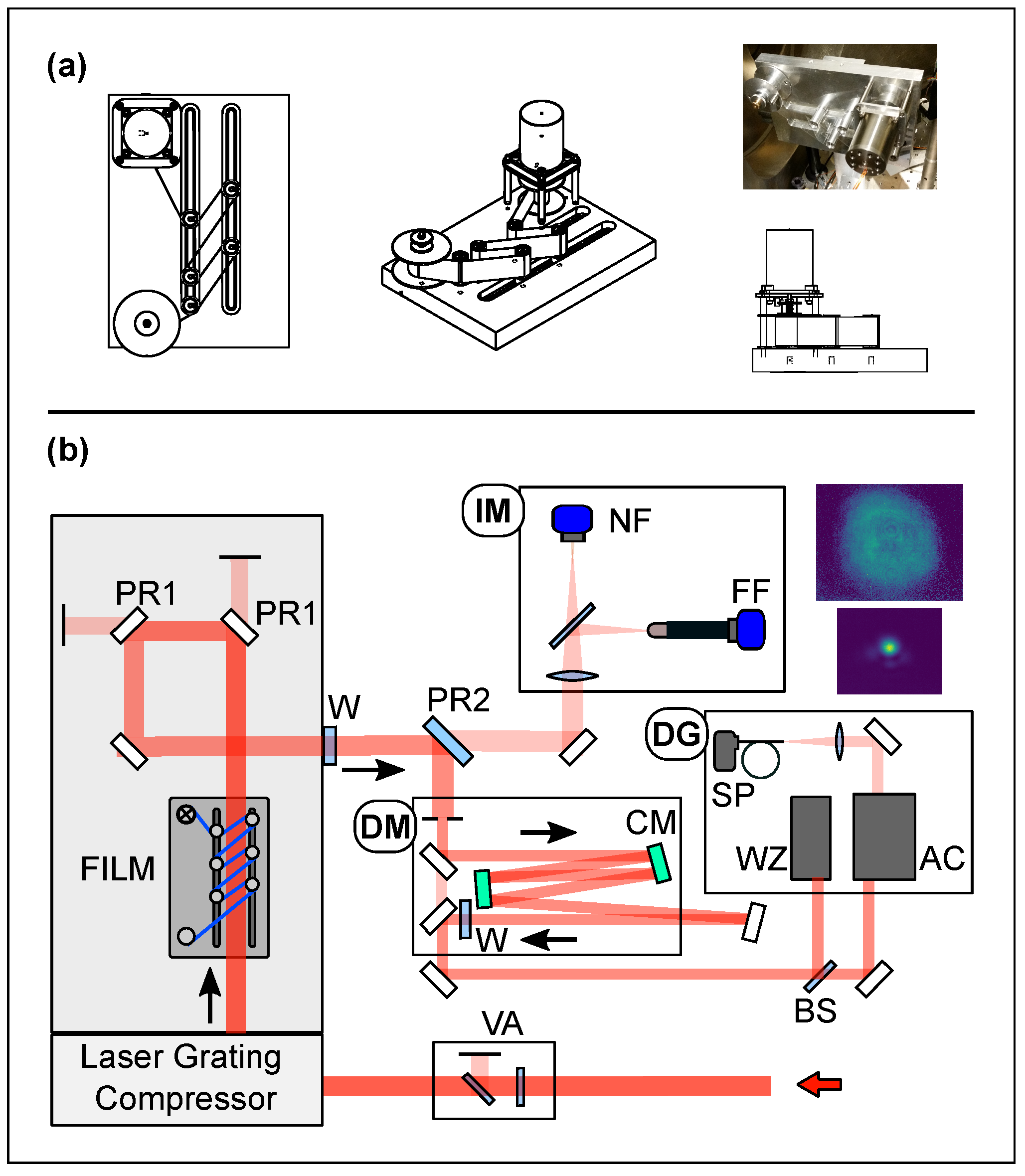
2. Experiment Setup
3. Results
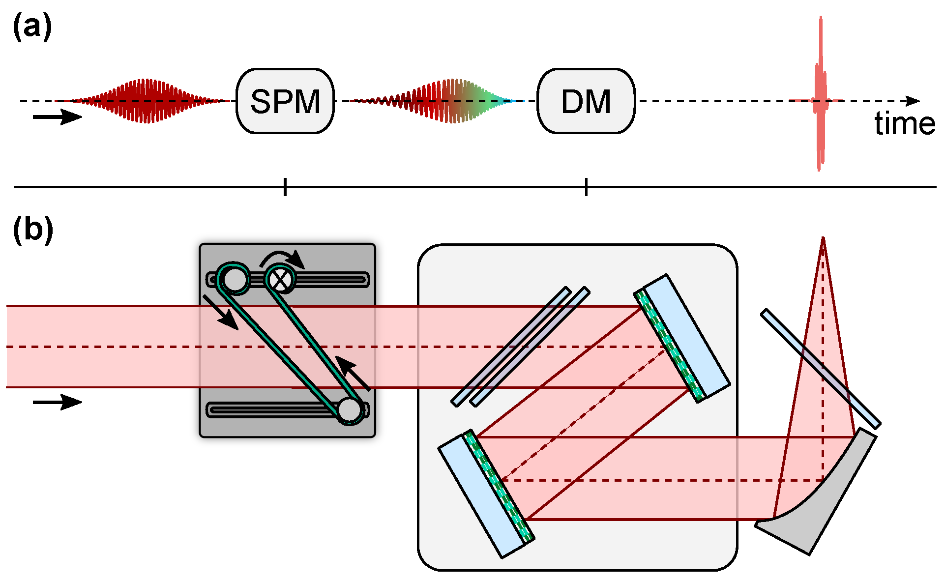
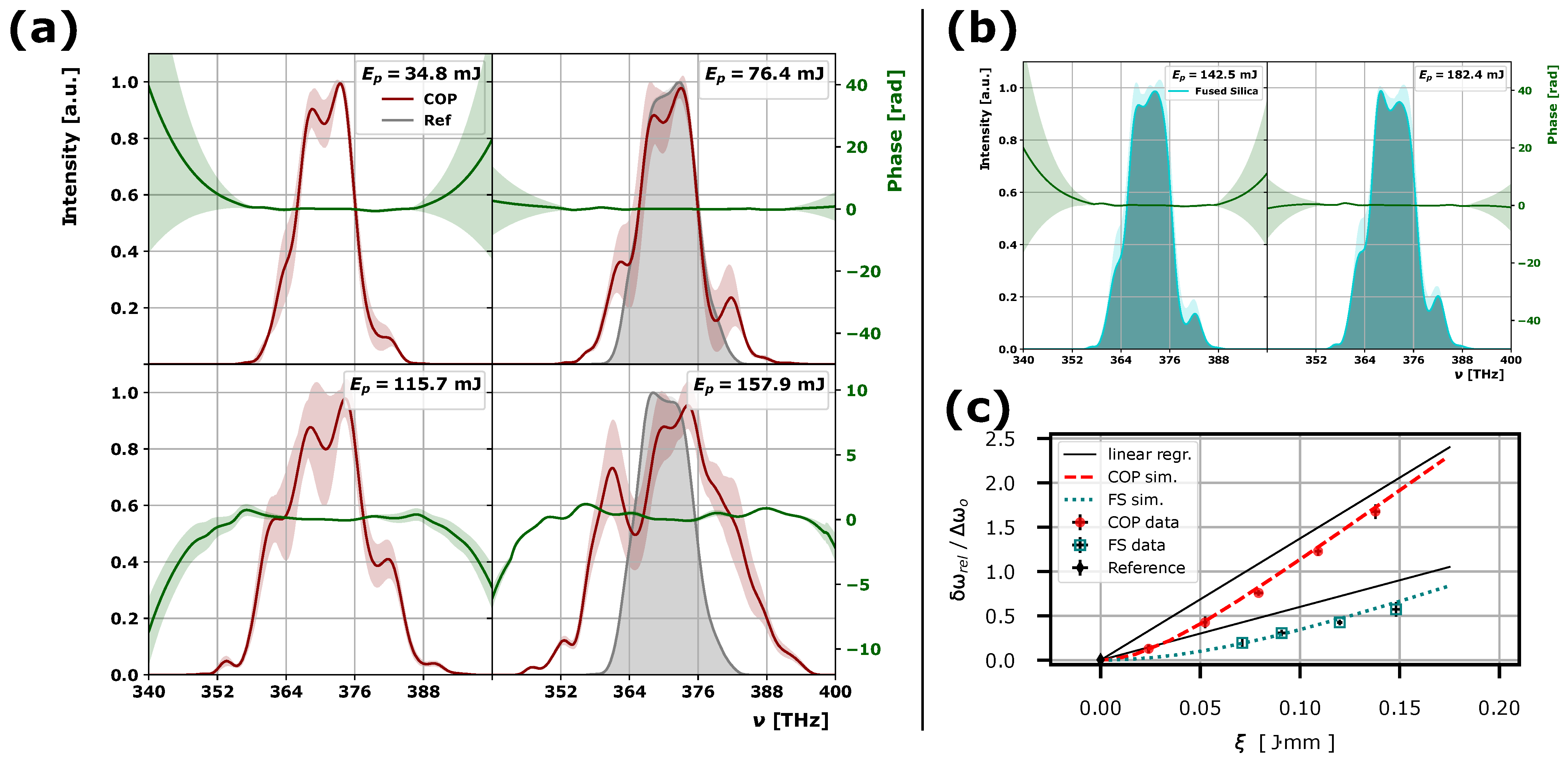
3.1. Nonlinear Material Response
3.2. Beam Profile
4. Discussion
5. Conclusions
Author Contributions
Funding
Institutional Review Board Statement
Informed Consent Statement
Data Availability Statement
Acknowledgments
Conflicts of Interest
References
- Strickland, D.; Mourou, G. Compression of amplified chirped optical pulses. Opt. Commun. 1985, 56, 219–221. [Google Scholar] [CrossRef]
- Dubietis, A.; Jonušauskas, G.; Piskarskas, A. Powerful femtosecond pulse generation by chirped and stretched pulse parametric amplification in BBO crystal. Opt. Commun. 1992, 88, 437–440. [Google Scholar] [CrossRef]
- Ple, F.; Pittman, M.; Jamelot, G.; Chambaret, J.P. Design and demonstration of a high-energy booster amplifier for a high-repetition rate petawatt class laser system. Opt. Lett. 2007, 32, 238. [Google Scholar] [CrossRef]
- Lureau, F.; Matras, G.; Chalus, O.; Derycke, C.; Morbieu, T.; Radier, C.; Casagrande, O.; Laux, S.; Ricaud, S.; Rey, G.; et al. High-energy hybrid femtosecond laser system demonstrating 2 * 10 PW capability. High Power Laser Sci. Eng. 2020, 8, e43. [Google Scholar] [CrossRef]
- Gales, S.; Tanaka, K.A.; Balabanski, D.L.; Negoita, F.; Stutman, D.; Tesileanu, O.; Ur, C.A.; Ursescu, D.; Andrei, I.; Ataman, S.; et al. The extreme light infrastructure—Nuclear physics (ELI-NP) facility: New horizons in physics with 10 PW ultra-intense lasers and 20 MeV brilliant gamma beams. Rep. Prog. Phys. 2018, 81, 094301. [Google Scholar] [CrossRef]
- Matras, G.; Lureau, F.; Laux, S.; Casagrande, O.; Radier, C.; Chalus, O.; Caradec, F.; Boudjemaa, L.; Simon-Boisson, C.; Dabu, R.; et al. First sub-25fs PetaWatt laser system. In Proceedings of the CLEO: 2013, San Jose, CA, USA, 11–13 June 2013; Paper CTh5C.5. OSA: Washington, DC, USA, 2013. [Google Scholar] [CrossRef]
- Zou, J.; Le Blanc, C.; Papadopoulos, D.; Chériaux, G.; Georges, P.; Mennerat, G.; Druon, F.; Lecherbourg, L.; Pellegrina, A.; Ramirez, P.; et al. Design and current progress of the Apollon 10 PW project. High Power Laser Sci. Eng. 2015, 3, e2. [Google Scholar] [CrossRef]
- Le Garrec, B.; Papadopoulos, D.N.; Le Blanc, C.; Zou, J.P.; Chériaux, G.; Georges, P.; Druon, F.; Martin, L.; Fréneaux, L.; Beluze, A.; et al. Design update and recent results of the Apollon 10 PW facility. In Proceedings of the SPIE 10238, High-Power, High-Energy, and High-Intensity Laser Technology III, Prague, Czech Republic, 26–27 April 2017; Hein, J., Ed.; International Society for Optics and Photonics: Bellingham, WA, USA, 2017; Volume 10238. [Google Scholar] [CrossRef]
- Nakamura, K.; Mao, H.S.; Gonsalves, A.J.; Vincenti, H.; Mittelberger, D.E.; Daniels, J.; Magana, A.; Toth, C.; Leemans, W.P. Diagnostics, Control and Performance Parameters for the BELLA High Repetition Rate Petawatt Class Laser. IEEE J. Quantum Electron. 2017, 53, 1–21. [Google Scholar] [CrossRef]
- Yoon, J.W.; Kim, Y.G.; Choi, I.W.; Sung, J.H.; Lee, H.W.; Lee, S.K.; Nam, C.H. Realization of laser intensity over 1023 W/cm2. Optica 2021, 8, 630. [Google Scholar] [CrossRef]
- Cartlidge, E. The light fantastic. Science 2018, 359, 382–385. [Google Scholar] [CrossRef] [PubMed]
- Naumova, N.M.; Nees, J.A.; Sokolov, I.V.; Hou, B.; Mourou, G.A. Relativistic Generation of Isolated Attosecond Pulses in a λ3 Focal Volume. Phys. Rev. Lett. 2004, 92, 063902. [Google Scholar] [CrossRef]
- Naumova, N.M.; Nees, J.A.; Mourou, G.A. Relativistic attosecond physics. Phys. Plasmas 2005, 12, 056707. [Google Scholar] [CrossRef]
- Ma, G.; Dallari, W.; Borot, A.; Krausz, F.; Yu, W.; Tsakiris, G.D.; Veisz, L. Intense isolated attosecond pulse generation from relativistic laser plasmas using few-cycle laser pulses. Phys. Plasmas 2015, 22, 033105. [Google Scholar] [CrossRef]
- Zhang, Y.X.; Qiao, B.; Xu, X.R.; Chang, H.X.; Yu, M.Y.; Zhong, C.L.; Zhou, C.T.; Zhu, S.P.; He, X.T. Intense single attosecond pulse generation from near-critical-density plasmas irradiated by a few-cycle laser pulse. Phys. Plasmas 2018, 25, 023302. [Google Scholar] [CrossRef]
- Zhou, M.L.; Yan, X.Q.; Mourou, G.; Wheeler, J.A.; Bin, J.H.; Schreiber, J.; Tajima, T. Proton acceleration by single-cycle laser pulses offers a novel monoenergetic and stable operating regime. Phys. Plasmas 2016, 23, 043112. [Google Scholar] [CrossRef]
- Wu, X.Z.; Gong, Z.; Shou, Y.R.; Tang, Y.H.; Yu, J.Q.; Mourou, G.; Yan, X.Q. Efficiency enhancement of ion acceleration from thin target irradiated by multi-PW few-cycle laser pulses. Phys. Plasmas 2021, 28, 023102. [Google Scholar] [CrossRef]
- Wheeler, J.A.; Mourou, G.; Tajima, T. Science of High Energy, Single-Cycled Lasers. Rev. Accel. Sci. Technol. 2019, 10, 227–244. [Google Scholar] [CrossRef]
- Tajima, T. Laser acceleration in novel media. Eur. Phys. J. Spec. Top. 2014, 223, 1037–1044. [Google Scholar] [CrossRef]
- Mével, E.; Tcherbakoff, O.; Salin, F.; Constant, E. Extracavity compression technique for high-energy femtosecond pulses. J. Opt. Soc. Am. B 2003, 20, 105. [Google Scholar] [CrossRef]
- Brabec, T.; Krausz, F. Intense few-cycle laser fields: Frontiers of nonlinear optics. Rev. Mod. Phys. 2000, 72, 545–591. [Google Scholar] [CrossRef]
- Goulielmakis, E.; Schultze, M.; Hofstetter, M.; Yakovlev, V.S.; Gagnon, J.; Uiberacker, M.; Aquila, A.L.; Gullikson, E.M.; Attwood, D.T.; Kienberger, R.; et al. Single-cycle nonlinear optics. Science 2008, 320, 1614–1617. [Google Scholar] [CrossRef] [PubMed]
- Cheng, Y.C.; Lu, C.H.; Lin, Y.Y.; Kung, A.H. Supercontinuum generation in a multi-plate medium. Opt. Express 2016, 24, 7224. [Google Scholar] [CrossRef] [PubMed]
- Ueffing, M.; Reiger, S.; Kaumanns, M.; Pervak, V.; Trubetskov, M.; Nubbemeyer, T.; Krausz, F. Nonlinear pulse compression in a gas-filled multipass cell. Opt. Lett. 2018, 43, 2070. [Google Scholar] [CrossRef]
- Lavenu, L.; Natile, M.; Guichard, F.; Zaouter, Y.; Delen, X.; Hanna, M.; Mottay, E.; Georges, P. Nonlinear pulse compression based on a gas-filled multipass cell. Opt. Lett. 2018, 43, 2252. [Google Scholar] [CrossRef]
- Mironov, S.Y.; Wheeler, J.; Gonin, R.; Cojocaru, G.; Ungureanu, R.; Banici, R.; Serbanescu, M.; Dabu, R.; Mourou, G.; Khazanov, E.A. 100 J-level pulse compression for peak power enhancement. Quantum Electron. 2017, 47, 173–178. [Google Scholar] [CrossRef]
- Fisher, R.A.; Kelley, P.L.; Gustafson, T.K. Subpicosecond Pulse Generation Using The Optical Kerr Effect. Appl. Phys. Lett. 1969, 14, 140–143. [Google Scholar] [CrossRef]
- Mourou, G.; Cheriaux, G.; Radier, C. Device for Generating a Short Duration Laser Pulse. U.S. Patent Application US20110299152A1, 8 December 2011. [Google Scholar]
- Mourou, G.; Mironov, S.; Khazanov, E.; Sergeev, A. Single cycle thin film compressor opening the door to Zeptosecond-Exawatt physics. Eur. Phys. J. Spec. Top. 2014, 223, 1181–1188. [Google Scholar] [CrossRef]
- Khazanov, E.; Mironov, S.Y.; Mourou, G. Nonlinear compression of high-power laser pulses: Compression after compressor approach. Uspekhi Fiz. Nauk 2019, 189, 1173–1200. [Google Scholar] [CrossRef]
- Mironov, S.Y.; Ginzburg, V.N.; Lozhkarev, V.V.; Luchinin, G.A.; Kirsanov, A.V.; Yakovlev, I.V.; Khazanov, E.A.; Shaykin, A.A. Highly efficient second-harmonic generation of intense femtosecond pulses with a significant effect of cubic nonlinearity. Quantum Electron. 2011, 41, 963–967. [Google Scholar] [CrossRef]
- Voronin, A.A.; Zheltikov, A.M.; Ditmire, T.; Rus, B.; Korn, G. Subexawatt few-cycle lightwave generation via multipetawatt pulse compression. Opt. Commun. 2013, 291, 299–303. [Google Scholar] [CrossRef]
- Mironov, S.; Lassonde, P.; Kieffer, J.C.; Khazanov, E.; Mourou, G. Spatially-uniform temporal recompression of intense femtosecond optical pulses. Eur. Phys. J. Spec. Top. 2014, 223, 1175–1180. [Google Scholar] [CrossRef]
- Mironov, S.Y.; Ginzburg, V.N.; Yakovlev, I.V.; Kochetkov, A.A.; Shaykin, A.A.; Khazanov, E.A.; Mourou, G.A. Using self-phase modulation for temporal compression of intense femtosecond laser pulses. Quantum Electron. 2017, 47, 614–619. [Google Scholar] [CrossRef]
- Bleotu, P.G.; Wheeler, J.; Papadopoulos, D.; Chabanis, M.; Prudent, J.; Frotin, M.; Martin, L.; Lebas, N.; Freneaux, A.; Beluze, A.; et al. Spectral broadening for multi-Joule pulse compression in the APOLLON Long Focal Area facility. High Power Laser Sci. Eng. 2022, 10, E9. [Google Scholar] [CrossRef]
- Mironov, S.Y.; Fourmaux, S.; Lassonde, P.; Ginzburg, V.N.; Payeur, S.; Kieffer, J.C.; Khazanov, E.A.; Mourou, G. Thin plate compression of a sub-petawatt Ti:Sa laser pulses. Appl. Phys. Lett. 2020, 116, 241101. [Google Scholar] [CrossRef]
- Ginzburg, V.; Yakovlev, I.; Zuev, A.; Korobeynikova, A.; Kochetkov, A.; Kuzmin, A.; Mironov, S.; Shaykin, A.; Shaikin, I.; Khazanov, E.; et al. Fivefold compression of 250-TW laser pulses. Phys. Rev. A 2020, 101, 013829. [Google Scholar] [CrossRef]
- Ginzburg, V.; Yakovlev, I.; Kochetkov, A.; Kuzmin, A.; Mironov, S.; Shaikin, I.; Shaykin, A.; Khazanov, E. 11 fs, 15 PW laser with nonlinear pulse compression. Opt. Express 2021, 29, 28297. [Google Scholar] [CrossRef] [PubMed]
- Kim, J.I.; Kim, Y.G.; Yang, J.M.; Yoon, J.W.; Sung, J.H.; Lee, S.K.; Nam, C.H. Sub-10 fs pulse generation by post-compression for peak-power enhancement of a 100-TW Ti:Sapphire laser. Opt. Express 2022, 30, 8734. [Google Scholar] [CrossRef]
- Available online: https://www.zeonex.com/displays-touch-sensors.aspx.html (accessed on 24 February 2017).
- Laserix. Available online: http://hebergement.u-psud.fr/laserix/en/Laserix (accessed on 12 December 2019).
- Lassonde, P.; Mironov, S.; Fourmaux, S.; Payeur, S.; Khazanov, E.; Sergeev, A.; Kieffer, J.C.; Mourou, G. High energy femtosecond pulse compression. Laser Phys. Lett. 2016, 13, 075401. [Google Scholar] [CrossRef]
- Taylor, A.J.; Clement, T.S.; Rodriguez, G. Determination of n2 by direct measurement of the optical phase. Opt. Lett. 1996, 21, 1812. [Google Scholar] [CrossRef]
- Hult, J. A Fourth-Order Runge – Kutta in the Interaction Picture Method for Simulating Supercontinuum Generation in Optical Fibers. J. Light. Technol. 2007, 25, 3770–3775. [Google Scholar] [CrossRef]
- Bespalov, V.; Talanov, V. Filamentary Structure of Light Beams in Nonlinear Liquids. ZhETF Pisma 1966, 3, 471–476. [Google Scholar]
- Rubenchik, A.M.; Turitsyn, S.K.; Fedoruk, M.P. Modulation instability in high power laser amplifiers. Opt. Express 2010, 18, 1380–1388. [Google Scholar] [CrossRef] [PubMed]
- Voronin, A.A.; Zheltikov, A.M. Pulse self-compression to single-cycle pulse widths a few decades above the self-focusing threshold. Phys. Rev. A 2016, 94, 023824. [Google Scholar] [CrossRef]
- Mironov, S.Y.; Wheeler, J.A.; Khazanov, E.A.; Mourou, G.A. Compression of high-power laser pulses using only multiple ultrathin plane plates. Opt. Lett. 2021, 46, 4570. [Google Scholar] [CrossRef] [PubMed]
- Li, Z.; Kato, Y.; Kawanaka, J. Simulating an ultra-broadband concept for Exawatt-class lasers. Sci. Rep. 2021, 11, 151. [Google Scholar] [CrossRef] [PubMed]

 ), 12.0 (
  ), 8.25 (
  ) fs.
), 12.0 ( ), 8.25 ( ) fs.
) fs.
), 12.0 ( ), 8.25 ( ) fs.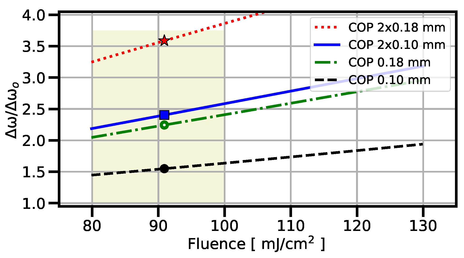

| Film | [mJ] | [J·mm] | [±0.4, THz] | [±2, nm] | [fs] |
|---|---|---|---|---|---|
| NA | all | – | 4.1 | 21 | 45.5 |
| COP | 35 | 0.025 | 4.6 | 24 | 43.3 |
| COP | 76 | 0.054 | 5.9 | 30 | 32.6 |
| COP | 116 | 0.081 | 7.2 | 37 | 29.4 |
| COP | 158 | 0.112 | 9.2 | 47 | 23.4 |
| FS | 143 | 0.071 | 4.9 | 25 | 39.8 |
| FS | 182 | 0.091 | 5.4 | 28 | 36.3 |
| FS | 240 | 0.120 | 5.9 | 30 | 31.9 |
| FS | 296 | 0.148 | 6.4 | 33 | 29.0 |
Publisher’s Note: MDPI stays neutral with regard to jurisdictional claims in published maps and institutional affiliations. |
© 2022 by the authors. Licensee MDPI, Basel, Switzerland. This article is an open access article distributed under the terms and conditions of the Creative Commons Attribution (CC BY) license (https://creativecommons.org/licenses/by/4.0/).
Share and Cite
Wheeler, J.; Bleotu, G.P.; Naziru, A.; Fabbri, R.; Masruri, M.; Secareanu, R.; Farinella, D.M.; Cojocaru, G.; Ungureanu, R.; Baynard, E.; et al. Compressing High Energy Lasers through Optical Polymer Films. Photonics 2022, 9, 715. https://doi.org/10.3390/photonics9100715
Wheeler J, Bleotu GP, Naziru A, Fabbri R, Masruri M, Secareanu R, Farinella DM, Cojocaru G, Ungureanu R, Baynard E, et al. Compressing High Energy Lasers through Optical Polymer Films. Photonics. 2022; 9(10):715. https://doi.org/10.3390/photonics9100715
Chicago/Turabian StyleWheeler, Jonathan, Gabriel Petrişor Bleotu, Andrei Naziru, Riccardo Fabbri, Masruri Masruri, Radu Secareanu, Deano M. Farinella, Gabriel Cojocaru, Razvan Ungureanu, Elsa Baynard, and et al. 2022. "Compressing High Energy Lasers through Optical Polymer Films" Photonics 9, no. 10: 715. https://doi.org/10.3390/photonics9100715
APA StyleWheeler, J., Bleotu, G. P., Naziru, A., Fabbri, R., Masruri, M., Secareanu, R., Farinella, D. M., Cojocaru, G., Ungureanu, R., Baynard, E., Demailly, J., Pittman, M., Dabu, R., Dancus, I., Ursescu, D., Ros, D., Tajima, T., & Mourou, G. (2022). Compressing High Energy Lasers through Optical Polymer Films. Photonics, 9(10), 715. https://doi.org/10.3390/photonics9100715