1. Introduction
To monitor the structural health and external environment of civil engineering, rail transit, aerospace, etc., and to ensure their safe operation, many kinds of sensors have been developed and widely used, one of which is the fiber Bragg grating (FBG) sensor [
1,
2,
3,
4,
5]. FBG sensors are drawing more and more attention due to their obvious advantages over traditional electrical sensors such as low loss, high reliability, strong electromagnetic interference resistance, high temperature resistance, and simple structure [
3,
6,
7]. The central wavelength of the FBG’s reflected spectrum will shift with the variation of the environment, such as temperature, pressure, ultrasonic, etc. These physical parameters can be detected by demodulating the FBG wavelength. However, there are still some existing problems that are urgently required to be solved, especially the need for FBG interrogators (FBGIs) with small size, high rate, and high performance [
8,
9,
10]. The existing commercial FBGIs based on discrete optoelectronic components, such as dynamic matched grating filters, tunable Fabry–Perot filters, CCDs, usually limit the development and application of FBG sensing technology because of their inferiorities in size and demodulation speed [
4,
11,
12,
13,
14]. In recent years, AWG-based photonic-integrated FBGI systems have gained attention because of their advantages of a compact structure, energy efficiency, and the possibility to realize high-speed interrogation, because the interrogation rate of the FBGI system is only affected by photodetector (PD) response time and AD sampling rate. As it is limited by the output characteristics of AWG, the currently reported demodulation system based on AWG cannot achieve a high resolution and a total measurement range. For example, in 2014 [
15], Gent university reported an AWG-based FBGI with a high dynamic range of 40 nm, whereas its resolution was only 5 pm; in 2017 [
16], Tianjin polytechnic university reported an AWG-based FBGI with a high resolution of 1 pm and the dynamic range was not mentioned; in 2019 [
17] University of Naples Federico II reported an AWG-based FBGI with a dynamic range of 0.8 nm without mentioning the resolution. Among all the material systems—including InP, silica, polymer, and silicon-on-insulator (SOI)—that can fabricate AWGs, the silicon-on-insulator (SOI) wafer with a top silicon layer and a buried
layer is the most promising one to realize the monolithic or hybrid integration of passive and active optoelectronic devices. This can come with a low cost, as SOI is compatible with the complementary metal oxide semiconductor (CMOS) technology [
7,
18,
19,
20,
21,
22,
23]. Additionally, an ultrasmall size of AWG can be achieved on an SOI-based platform because of its high relative refractive index difference between
and
, which offers high light field confinement and allows small-size waveguides and small-radius bent waveguides. However, most reported AWGs nowadays are basically designed for the communication application, while in the FBG sensing system, AWG with high bandwidth is preferred to get a large interrogation dynamic range [
24]. Thus, it is very crucial to design and fabricate a high-performance SOI-based AWG, which is applicable for FBGI system.
In this paper, we have fabricated several ultra-small AWGs with central wavelengths of 1550 nm and built an FBGI system with the AWGs embedded in. Due to AWG’s spectral characteristics, the wavelength resolution and measurement range, both of which are the AWG-based interrogator, are mutually constrained. To solve this problem, the performance of the interrogation system was analyzed with different diffraction orders (M) and different arrayed waveguide quantities (N). We have optimized the structure of AWG to make it more applicable for the FBGI system, which has high-bandwidth spectra by optimizing the diffraction order and arrayed waveguide quantities. We have tested the AWG’s central wavelength varying with temperature. The simulated and experimental analysis of the designed AWG is carried out from the aspects of spectral characteristics and interrogation performance.
2. Design and Simulation
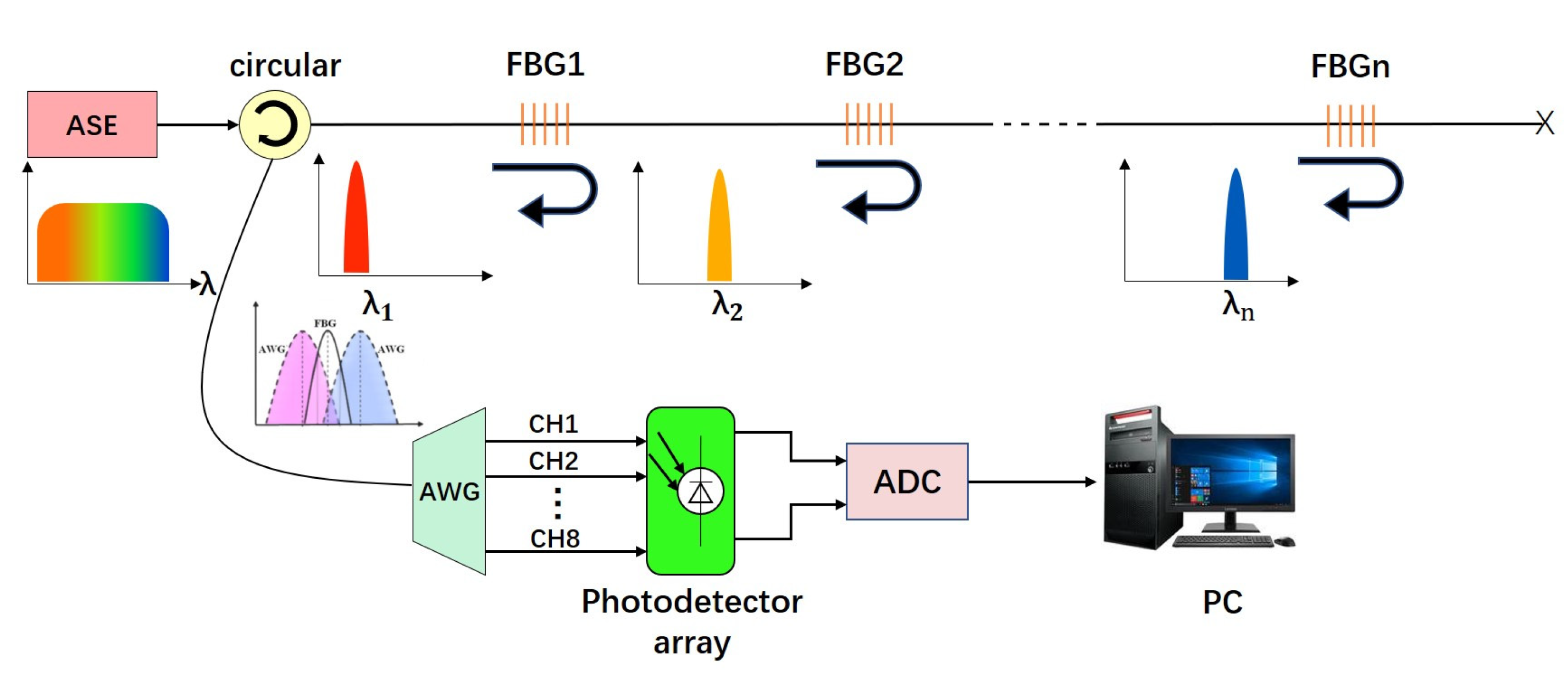
The proposed AWG interrogation system consists of an amplified spontaneous emission (ASE) broadband light source, an optical circular, FBGs, an AWG, PDs, and a data processing circuit as shown in
Figure 1 [
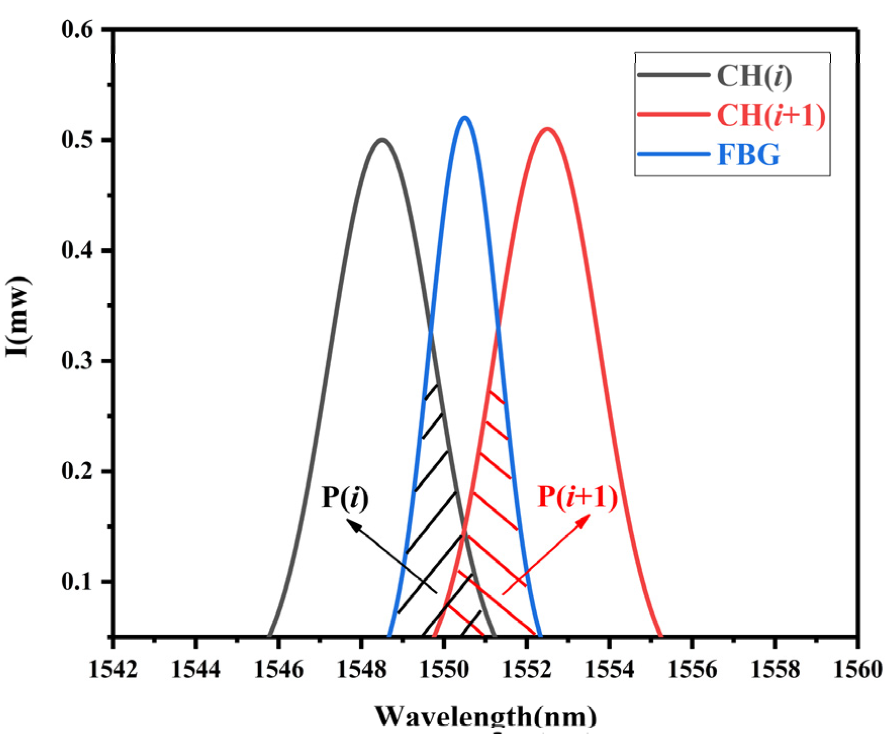
24]. When the reflected light from the FBG transmits to AWG, the spectrum of FBG will overlap with the transmission spectra of AWG.
and
are the maximum two output light power values of the AWG, which are the convolutions of the FBG reflection spectrum and two adjacent channel transmission spectra of the AWG, respectively (see
Figure 2). The central wavelength of FBG (
) exhibits linear function with the logarithm of light power ratio of AWG’s two adjacent channels (
), as shown in Equation (5). Employing Equation (5), the FBG wavelength can be interrogated by detecting
and
.
The transmission spectra of each channel of AWG can be assumed to be a Gaussian-like function, and the equation for the channel (
i) of the AWG can be depicted as:
where
is the normalization factor of AWG transmission spectrum;
indicates the central wavelength of AWG Channel (
i);
is the full width at half maximum (FWHM) of the AWG spectra.
Supposing the reflection spectrum of FBG is Gaussian, the reflection spectral equation of it will be:
where
is the normalization factor of FBG transmission spectrum;
is the central wavelength of fibber Bragger grating (FBG); Δ
is the full width at half maximum (FWHM) of the FBG spectrum.
The output optical power of AWG each channel is the integral of the light source power, FBG’s reflection spectrum and AWG’s transmission spectrum in the hole spectral region. As a result, the output optical power of AWG’s channel (
i) and channel (
i + 1) is as follows:
where
and
are the decay factors of channel (
i) and channel (
i + 1);
is the optical power of the light source.
As we can recognize from Equations (1) and (2), the output optical power of AWG is closely related to the relative position of the peak wavelengths of AWG and FBG. Within a narrow wavelength range, the output optical power of broadband light source can be considered as a fixed value. Assuming that the channel spacing, full width at half maximum (FWHM), and the propagation coefficients of AWG each channel are identical, the relationship between the optical power ratio of AWG adjacent channels and FBG center wavelength is:
Equation (5) shows the interrogation algorithm of FBG wavelength, which is that the logarithm of the output optical power ratio of AWG two adjacent channels has a linear relationship with the reflected wavelength of FBG sensor. Thus, we only need to use photodetectors (PDs) to detect the AWG output optical power to demodulate the central wavelengths of FBGs.
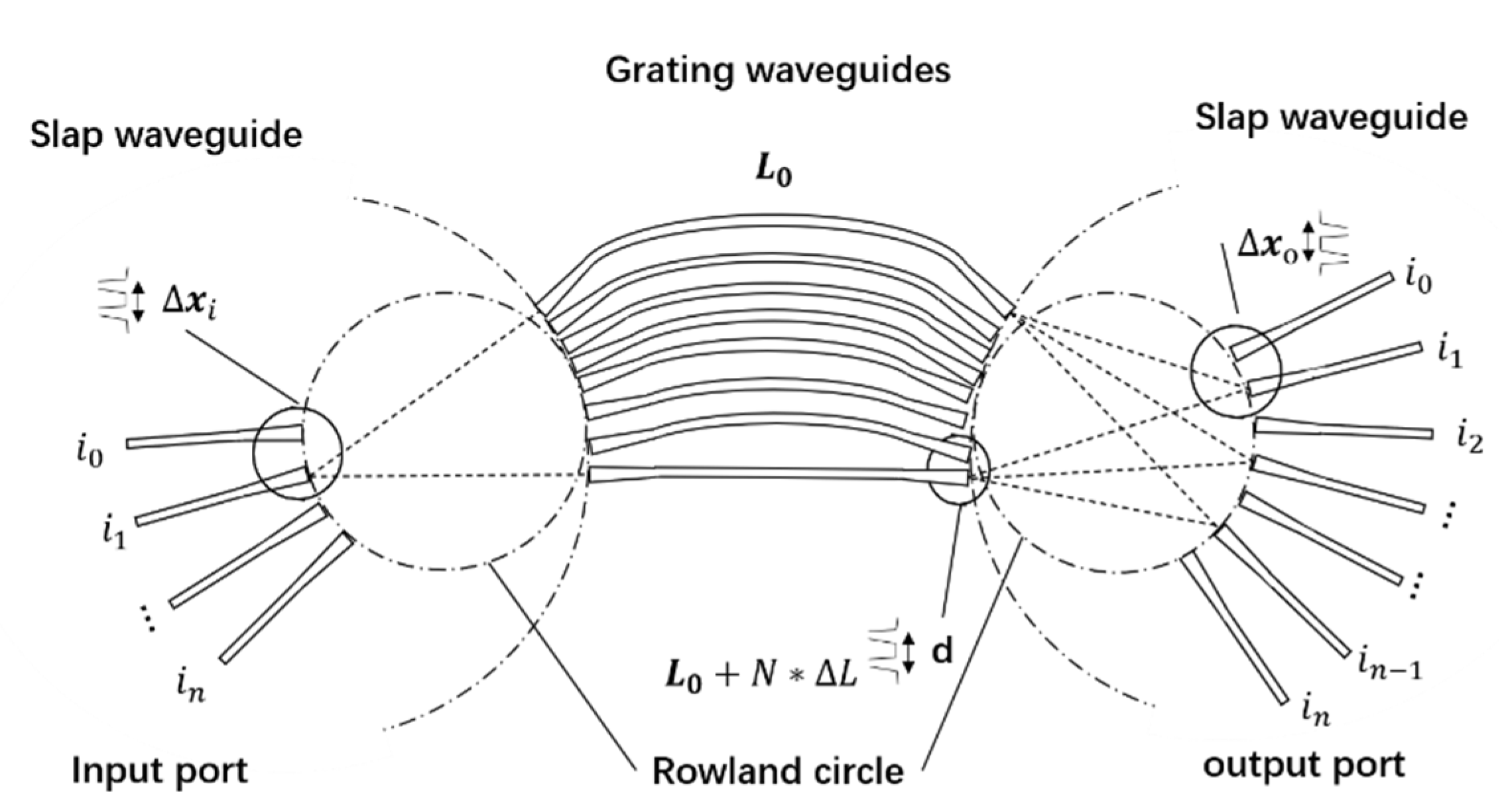
The interrogation performance of the above FBGI system is closely related to the spectral characteristic of AWG, which is composed of input/output waveguides and two free propagation regions (FPRs) that are designed to provide focusing functionality, connected by an array of waveguides featuring a constant incremental optical path difference. The structural diagram of AWG is shown in
Figure 3.
A beam of broad-band light transmitting through the input waveguide, diffracts in the first and then is coupled into the arrayed waveguides. Before transmitting into the second , the optical signals in adjacent arrayed waveguides have the same phase difference because of the same length difference () in adjacent arrayed waveguides. The optical signals from different arrayed waveguides diffract and interfere with each other in the second , and then the light of different wavelengths will focus on different location, finally outputting form different output waveguides.
We define
as minimum separation output waveguides,
as the path length difference of the adjacent arrayed waveguides,
as the minimum separation of arrayed waveguides,
as the diffraction order,
and
as the wavelength in free-space, respectively, and
as the wavelength spacing. The relationships between these parameters are shown below.
where
is the diffraction order of the array,
is the center operating wavelength of AWG,
is the effective index of the arrayed waveguide,
is the spacing of the adjacent channel,
is the free spectral range of the device,
is the effective index of the slab waveguide,
is the group index, channel spacing,
is the diameter of the Rowland circle, and
is the maximal number of the output waveguides.
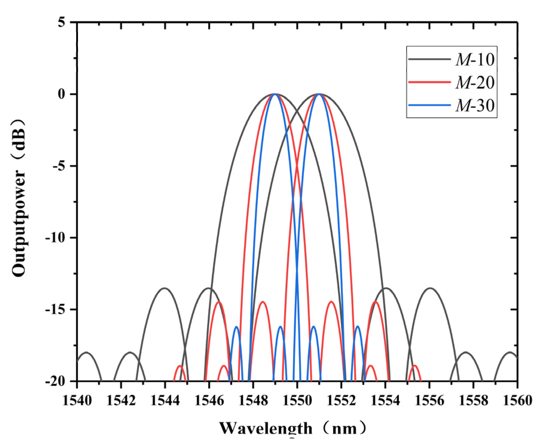
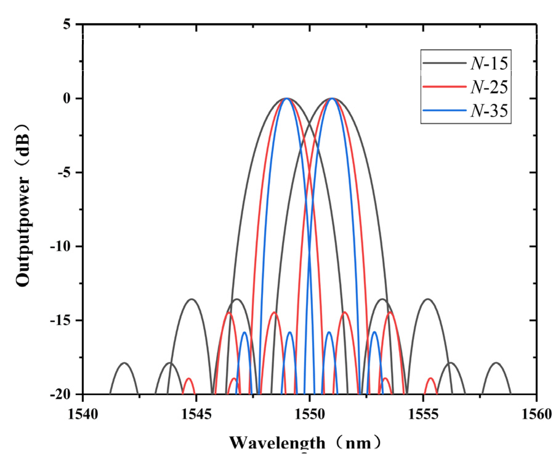
AWGs with different diffraction orders (
) and arrayed waveguide numbers (
) are designed to illustrate their impact on the spectral characteristic of AWG. Some parameters of AWG are revealed in
Table 1.
Figure 4 and
Figure 5 respectively shows the variation of transmission spectrum of two adjacent AWG channels under different diffraction orders and different array waveguide numbers. The principle of the demodulation system is that the central wavelength of the fiber Bragg grating (
) is placed between the central wavelength of the adjacent channel of the AWG, if central wavelength of the Bragg shifts, the power distribution in each of the adjacent channels will change. Therefore, when the AWG is used for demodulation, its transmission spectrum needs to have small crosstalk and large overlap range to improve the measurement range and accuracy of the system. If the crosstalk between the adjacent AWG channels gets smaller and the overlap area becomes larger, the demodulation performance of the system will be better. From
Figure 4, we can see that the overlap area and crosstalk of the adjacent channel become smaller when the diffraction order (M) and number of the arrayed waveguides (N) get higher. Through the simulation we find that when M = 20 and N = 25, the transmission spectrum of AWG has relatively small crosstalk and large overlap range at the same time, which is suitable for the demodulation system. Some parameters of the AWGs are shown in
Table 1.
With the optimized parameters of diffraction order and arrayed waveguide number, the spectrum of AWG is presented in
Figure 6, from which we can conclude that the AWG has good transform spectrum with central channel loss of −3.18 dB, nonuniformity below 0.4
, crosstalk below −16
, and 3
bandwidth about 1.3
.
3. Device Structure and Experiment
Our SOI-based multi-channel AWG is fabricated on silicon-on-insulator (SOI) wafer with a top silicon layer, and a buried
layer.
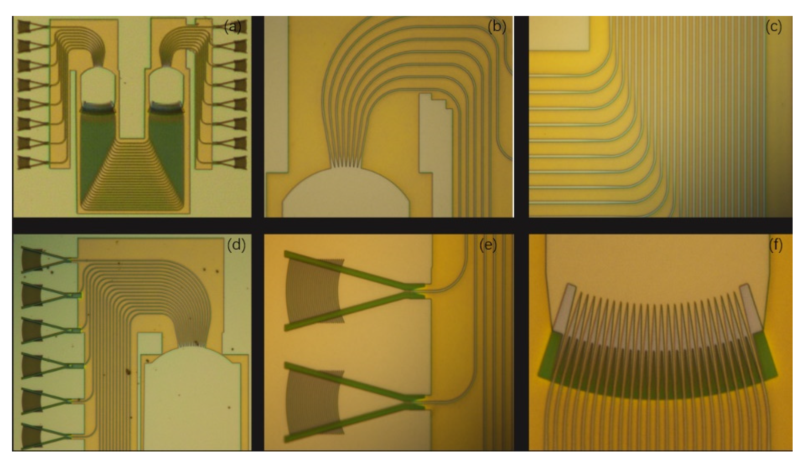
Figure 7 is the microscope graphs of fabricated 8 × 8 AWG.
Figure 7a shows the complete structure of the AWG,
Figure 7b shows the output waveguides,
Figure 7c shows the arrayed waveguides,
Figure 7d shows the input waveguides,
Figure 7e shows the grating couplers, and
Figure 7f shows the bi-level-tapers which have been proven to be effective in reducing the crosstalk caused by optical field coupling while maintaining a high mode converting efficiency [
16]. The core size of the fabricated AWG is 335 × 335 μm
2.
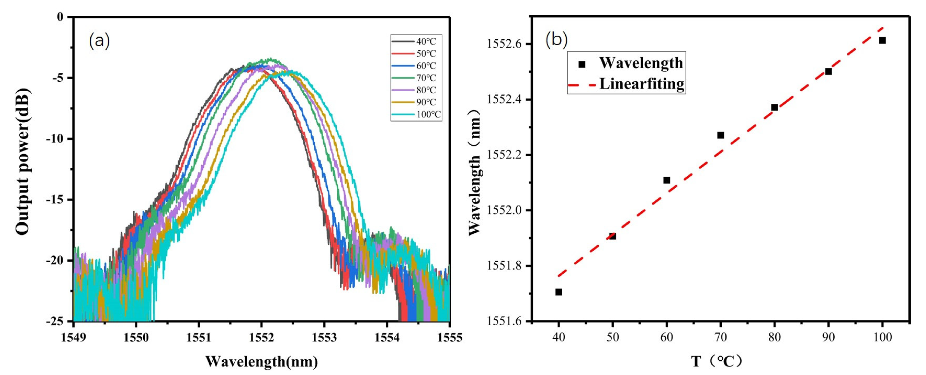
The
of AWG is affected by temperature. The spectral characteristic, namely the peak wavelength of AWG is temperature related, which is caused by the dependence of
nc on the temperature. Relationship between each channel’s central wavelength and temperature is as follows:
where
is the central wavelength of each channel’s transmission spectrum,
is the temperature of AWG,
is the original temperature of AWG and
is the value of
and
.
Figure 8 shows the test result of AWG’s central wavelength varying with temperature.
Figure 8a is the transmission spectra at different temperatures of the fifth output channel (CH5) of the AWG and
Figure 8b is the relationship between the central wavelength of CH5 and temperature of AWG.
We can see that the output characteristics of AWG are influenced by temperature and that the central wavelength of each channel’s output spectrum will drift with temperature. This phenomenon will reduce the accuracy of the interrogation system, so we did experiments in the ultra-clean room with a constant temperature.
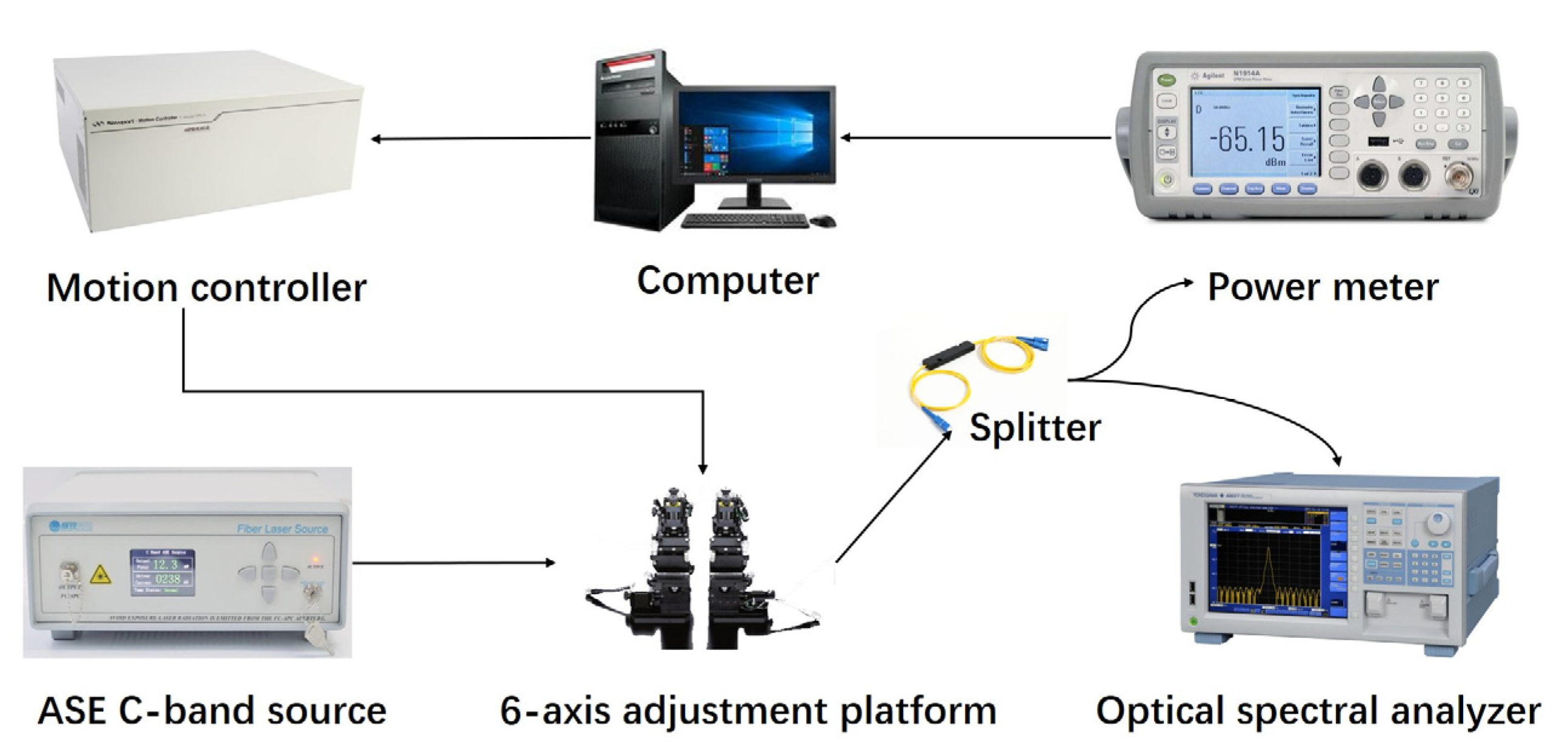
Figure 9 shows the testing system for the spectra measurement of the fabricated AWG. The optical signal from an ASE C-band source is coupled into AWG’s input waveguide on the 6-axis adjustment platform through a single-mode lens fiber. Afterwards the light from AWG’s output waveguide is coupled into a 1 × 2 splitter connected to an optical spectral analyzer and a power meter, respectively. The optical signal that travels through the power meter is converted into a digital signal which can be recognized by the computer that is an important reference for using the computer to control the motion controller, which is used to implement the rigid control of the 6-axis adjustment platform.
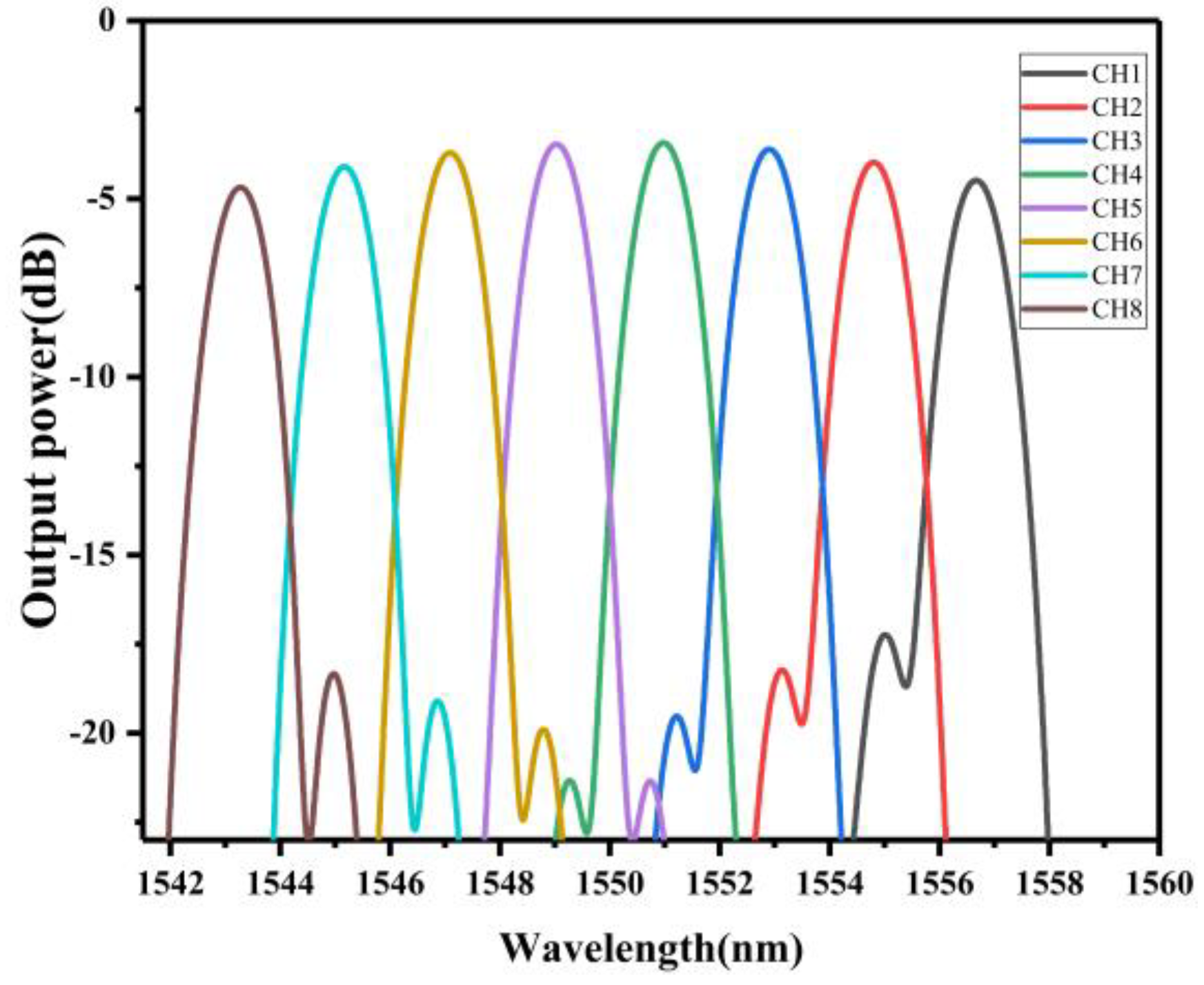
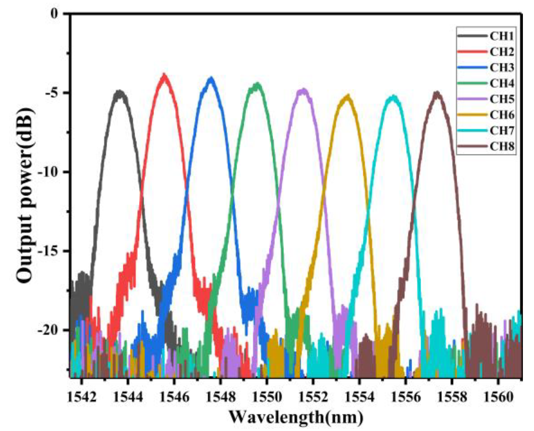
The transmission spectrum shows that the fabricated AWG exhibits a central channel loss of −4.35 dB, loss uniform of 0.8 dB, and crosstalk level of −15.4 dB, as shown in
Figure 10. The amplitude of transmission spectrum of each channel is not uniform which is partially caused by the difference from the coupling loss of each channel of AWG.
Due to the limitation of inductively coupled plasma technology, the produced waveguide will produce manufacturing errors. Thus, there are differences between the simulation and experimental results. Nevertheless, the transmission spectrum of the device has reached the expected performance in terms of crosstalk, nonuniformity and insertion loss (see
Table 2).
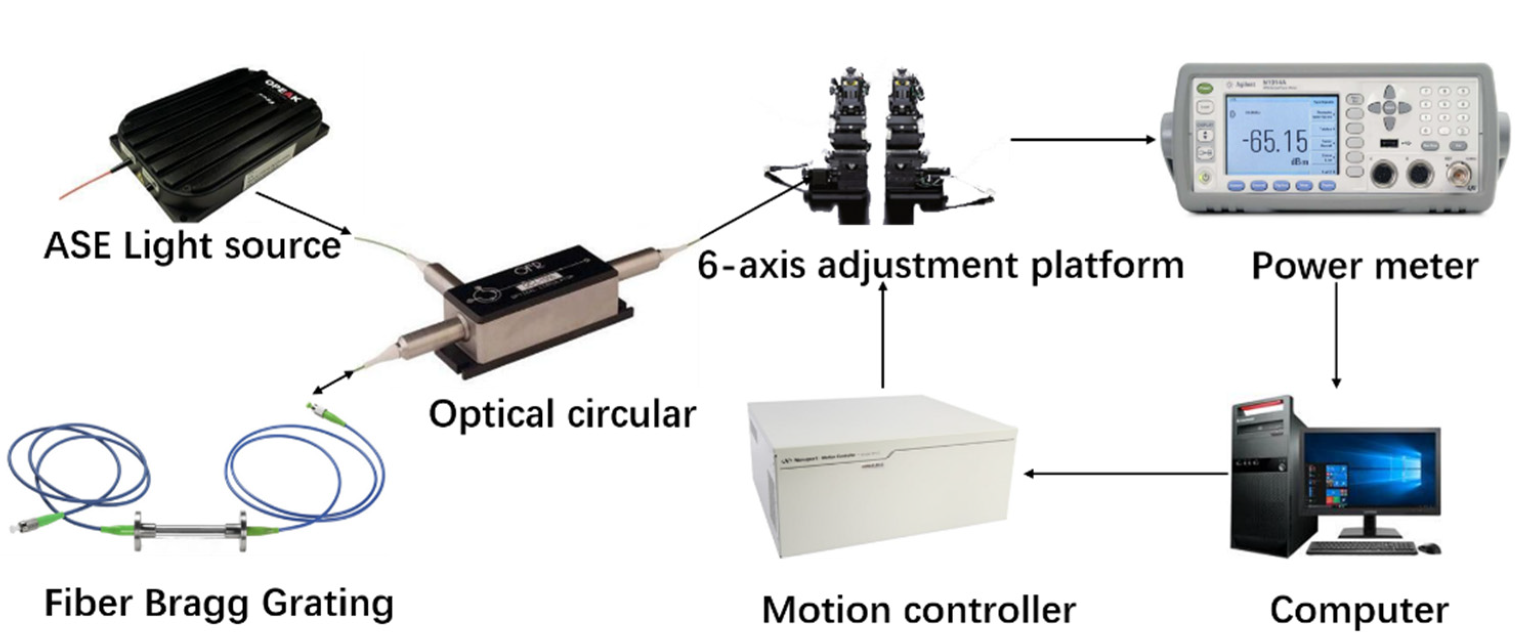
Figure 11 shows the testing system for the interrogation performance measurement of the fabricated AWG. The broadband light emitted by the ASE is coupled through a single-mode fiber into the fiber Bragg grating, which is located on the temperature control table. The light reflected from the FBG pass through the optical circular and then transmits to AWG which is placed on a 6-axis adjustment platform. Then optical signal from AWG’s output waveguide travels into the power meter. Finally, the optical signal is converted into electrical signal by optical power meter. The motion controller is used to adjust the position of the output coupling fiber to collect the maximum optical power of each output channels.
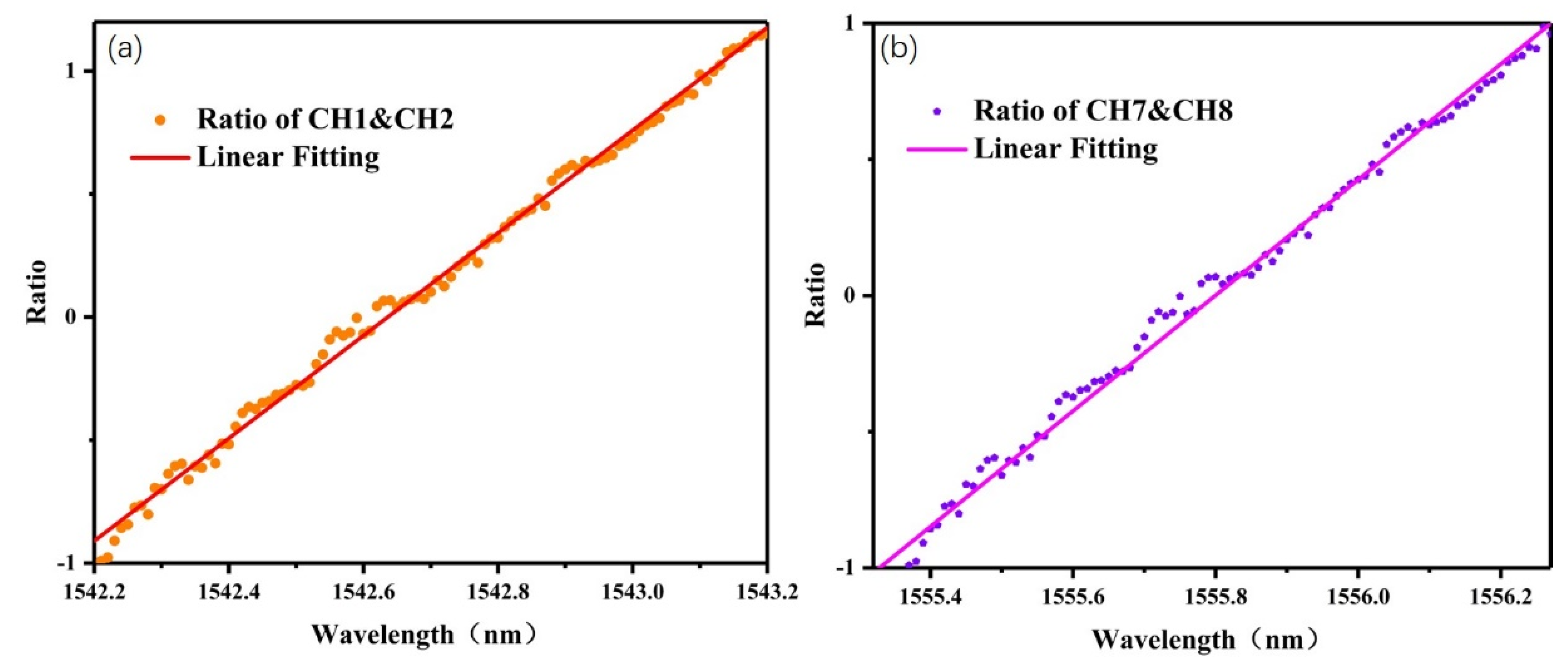
Based on Equation (5), we experimentally analyzed the relationship between the logarithm of the output optical power ratio (
) of AWG adjacent channels (AWG channel 1 and 2 and channel 7 and 8, respectively, as shown in
Figure 12a,b, and the peak wavelength of FBG. The relationship between the logarithm of the optical power ratio and the peak wavelength of the FBG is obtained by linear fitting. The root mean square (RMS) of the fitting line and the experimental data is 20.9
, so that the measured wavelength precision of the AWG based FBGI system is 20.9
. The wavelength sensitivity of each FBG is between 1.3 and 1.75 dB/nm, which is relatively high and promising to get a high wavelength resolution. The demodulating range in this paper is about 1 nm, less than the channel spacing of AWG, because the adjacent channel crosstalk of AWG is not negative infinite. The experimental results in this paper show that the AWG based FBG interrogation system is an excellent choice for fiber Bragg grating sensing systems.
We made a comparation of proposed interrogation system and the interrogation system of recent studies [
16,
24] (see
Table 3). The proposed interrogation system has good performance in dynamic range, resolution and accuracy.

 ,
, 


