Abstract
We propose a method for measuring the terahertz properties for two principal optical axes of anisotropic crystals without optical activity using terahertz time-domain spectroscopy (THz-TDS). The method put forward in this paper utilizes the inherent polarization sensitivity of the THz-TDS electro-optic detection system. We demonstrate the practical application of the method by measuring the temperature dependence of the refractive index and the absorption coefficient of a lithium triborate crystal for three optical axes.
Keywords:
terahertz; THz-TDS; polarimetry; refractive index; absorption; anisotropy; lithium triborate; LBO 1. Introduction
Terahertz time-domain spectroscopy (THz-TDS) is a mature technique that allows for measuring the optical, dielectric, and conductivity properties of materials in the terahertz spectral range. It is commercially available and has a wide range of applications spanning various domains of science, technology, and art. It is used for studying biological tissues and molecules, complex chemical compounds and crystalline materials, as well as for the nondestructive evaluation of drugs, electronic components, and cultural heritage objects. While THz-TDS is used for these practical purposes, its techniques continue to evolve [1]. Examples of such developments include accessing terahertz nonlinear optics by increasing radiation power [2,3]; methods for probing nanoscale phenomena [3]; time-resolved pump-probe techniques for studying ultrafast processes, such as carrier dynamics; and studying anisotropic materials by enhancing polarization sensitivity [4].
Several methods were developed to measure the polarization of terahertz radiation in THz-TDS. One approach relies on detectors that are capable of sensing two orthogonal polarizations simultaneously. This is achieved by using either two separate electro-optic detectors [5,6,7] or three- or four-contact photoconductive antennas (as opposed to conventional two-contact units) [8,9,10,11]. The inherent dependence of electro-optic detection sensitivity on the polarization of terahertz and probe laser radiation can also be employed [12,13]. In this case, a detector crystal [14,15,16], the probe pulse polarization [17], or the polarization of the generated terahertz radiation [18] is steadily rotated and the signal is measured using lock-in techniques at the rotation frequency or its harmonics. The polarization state of terahertz radiation can also be derived from measurements performed at three azimuthal angle positions of terahertz polarizers [19]. Setups with a steady rotation of polarizers at 5−15 Hz with lock-in measurements at twice the rotation frequency are also suggested [20,21,22].
The above approaches are currently under development in laboratories and are not available as commercial solutions to regular users of terahertz time-domain spectrometers. In this light, it is important to develop easy-to-apply terahertz polarimetry methods utilizing off-the-shelf components, such as high-contrast polarizers, to improve the accuracy and speed of measurements.
In this article we propose a method that makes use of high-contrast wideband terahertz polarizers to measure properties for two principal optical axes of anisotropic crystals without optical activity. Our approach takes into account the polarization sensitivity of electro-optic detection and does not require samples to be rotated to align their axes along the polarization direction of terahertz waves. Instead, the polarization of terahertz radiation is aligned with the help of polarizers. This technique can be beneficial in studying anisotropic crystals placed in a cryostat, a heating cell, or any closed chamber.
2. Sensitivity of Electro-Optic Detection in Terahertz Time-Domain Spectroscopy
In a THz-TDS electro-optic detection system, terahertz radiation changes the refractive index of a nonlinear detector crystal, then these changes are sensed by probe laser pulses and produce a terahertz signal. The system sensitivity, η, i.e., the ratio of the detected terahertz signal, STHz, to the electric field of terahertz radiation, ETHz, depends on the polarization of terahertz and probe laser radiation. The sensitivity also depends on the probe laser intensity, Ip, and the physical properties of the detecting crystal, namely its refractive index, n, at the probe radiation frequency, electro-optic coefficient, r, and length, L. The full formula for the sensitivity, η, can be written as follows [13]:
where ω is the terahertz frequency, c is the speed of light, and the function F(α, β) describes the dependence of the measured signal on the terahertz and probe laser radiation polarization angles relative to the detecting crystal’s orientation.
Here we analyze only the function F(α, β). For the case of the (110)-cut zincblende detecting crystal, it can be formulated as follows [12]:
where α and β are the angles between the z-axis of the detection crystal and the polarization direction of terahertz and probe laser radiation, respectively. The function F110(α, β) is shown in Figure 1. As determined earlier [12], the maximum absolute value of is achieved at α = 90° and β = 0° or 90°.
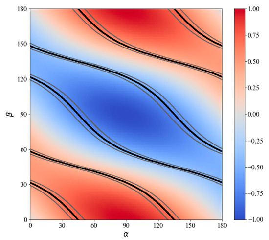
Figure 1.
Dependence of the measured signal on the terahertz and probe radiation polarization angles (α and β, respectively) relative to the z-axis of the (110)-cut zincblende detection crystal.
In our study, instead of aiming to adjust the electro-optic detection system to achieve the maximum absolute value of F(α, β), we seek values of angles α and β providing the same sensitivity for two orthogonal terahertz polarizations, i.e., pairs of α satisfying the condition α2−α1 = 90°. For each fixed β in Equation (2), we find pairs of orthogonal α that provide the same sensitivity (see the black curves in Figure 1). The absolute values of F110(α, β) on the found curves vary from to . The grey curves in Figure 1 represent a 10% deviation bound of the optimum value.
The highest absolute value of is achieved at angles β = 0° or 90° for two orthogonal terahertz polarization angles, α1 = 45° and α2 = 135° (−45°), simultaneously. The optimum value of F110 changes by less than 10% within the range of α = 39.52° − 51.06°.
We can perform a similar analysis for (111)-cut zincblende crystals that are also used in THz-TDS. The formula from [13] can be applied for the particular case of a (111)-cut detection crystal to calculate the function F111(α, β), as follows:
where α and β are angles between the (−211)-axis of the detection crystal and the polarization direction of terahertz and probe radiation, respectively. The function F111(α, β) is depicted in Figure 2. The maximum absolute value of is achieved at α = 90° and β = 0° or 90° too. However, in contrast to the case of (110)-cut crystal, the same maximum absolute value of is also achieved at a set of angles α and β satisfying the following condition: , where n is an integer value.
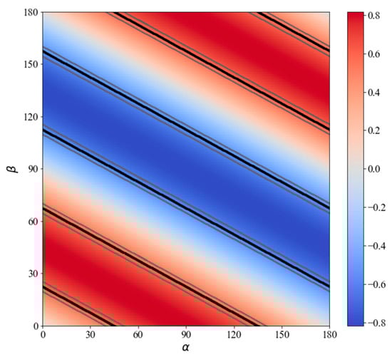
Figure 2.
Dependence of the measured signal on the terahertz and probe radiation polarization angles (α and β, respectively) relative to the (−211) axis of the (111)-cut zincblende detection crystal.
It also can be seen from Figure 2 and the analysis of Equation (3) that the value of is achieved simultaneously for two orthogonal terahertz polarizations, if angles α and β satisfy the following condition: , where n is an integer value (see the black lines in Figure 2, the grey lines represent a 10% deviation bound of the optimum value). A special case for this condition is α = 45° and 135° (or −45°) with β = 0° or 90°. These values of angles α and β are the same as for the (110)-cut detection crystal.
3. Method of Terahertz Measurements for Orthogonal Axes of Anisotropic Crystals
The above analysis, as performed for different THz-TDS detection systems, can serve as the basis for a method to study the properties of anisotropic crystals without optical activity for its two principal optical axes. The starting point is a conventional terahertz generation and detection system setup allowing for the maximum sensitivity. More specifically, the probe radiation polarization angle is set up at β = 0° or 90°, and the terahertz radiation polarization angle is α = 90°. We also utilize two high-performance broadband terahertz polarizers, with the first of those installed after the generator and the other before the detector (see Figure 3). Let φ denote an azimuthal rotation angle of polarizers relative to the same detector crystal axis from which the angles α and β are measured. Initially, both polarizers are also set at an angle of φ = 90° that corresponds to the maximum transmission of terahertz radiation.
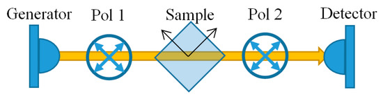
Figure 3.
Schematic of the suggested measurement method.
If we rotate both polarizers simultaneously at an angle of φ = ±45° they will transmit of the generated terahertz signal. The sensitivity of the detection system for terahertz radiation polarized at ±45° is of the maximum sensitivity because , as discussed in the previous section. Thus, we obtain 0.5 of the maximum amplitude compared to the ideal case of fully transmitting terahertz polarizers. Despite losing part of the signal, we can study the terahertz properties of anisotropic crystals for two principal optical axes with the same sensitivity in this configuration.
Let us consider the following measurement method after the initial tuning (Figure 3). The sample is set up diagonally in such a way that its axes are set at roughly ±45° and fixed in a cryostat or a heating cell. After that, the polarizers and the sample axes are aligned. To do so, the second polarizer is rotated by 90° relative to the first one. In the absence of a sample, no signal can be detected due to the high extinction ratio of the polarizers. However, when a sample is inserted into the terahertz beam, a small signal is detected since the crystal axes are not positioned at the exact angles of ±45°. By simultaneously rotating two polarizers by a small angle δ and keeping them orthogonal to each other, we can achieve zero signal at some angle φ = 45° + δ. This indicates that the input THz polarization is aligned along the optical axis of the crystal. No signal is also achieved at angle φ = 45° + δ − 90° = −45° + δ for the other optical axis.
Thus, both polarizers can be aligned along the crystal optical axes at angles close to ±45°, which provides a detection sensitivity in the vicinity of of the maximum sensitivity, as per the analysis demonstrated earlier. The sample and reference terahertz pulses can then be measured for both optical axes and the terahertz properties can be calculated based on them.
4. Demonstration of the Suggested Method on an LBO Crystal
To check the efficiency of the suggested method we measured the terahertz optical properties of the lithium triborate crystal (LiB3O5, LBO) at different temperatures. It is a negative biaxial nonlinear crystal belonging to the mm2 point group. Its crystallographic axes are assigned to the optical ones as follows, a, b, c → x, z, y. We studied LBO crystals grown in MoO3 flux using a modified Kyropoulos method in the Sobolev Institute of Geology and Mineralogy of the Siberian Branch of the Russian Academy of Sciences [23,24]. The samples were a-cut (x-cut) and c-cut (y-cut) polished plane-parallel plates 10 × 10 mm2 in size with a thickness of 2065 and 2069 μm, respectively.
We measured the terahertz spectra using a custom-made terahertz time-domain spectrometer based on an FFS femtosecond fiber laser (Toptica Photonics, Gräfelfing, Germany). We also utilized a measurement setup with alternating sample and reference measurements. In this setup, a sample holder had two identical apertures: the sample was placed in the first one, and the second one remained vacant [25]. The sample holder was placed in a bath cryostat with a heating element that allowed for the stabilization of the temperature in the range of −195 °C and 23 °C with an accuracy of 0.1 °C. The measurements were performed at temperatures of −195 °C, −120 °C, −50 °C, and 23 °C. We used an ILS50HA motorized linear translation stage (Newport, RI, USA) to move the whole cryostat to alternate between the two identical apertures in the sample holder. Metal-grid polarizers on polymeric thin films were used as a part of the setup [26]. These robust and easy-to-handle polarizers assembled in a tandem structure [27] had a power extinction ratio of over 105:1 in a range of frequencies from 0.2 to 2 THz. The polarizers were mounted on precision rotation stages 8MR190-2-28 (Standa, Vilnius, Lithuania), with a full step resolution of 0.6′.
The measurement results obtained at room temperature are presented in Figure 4. The optical properties agree well with the previous measurements obtained by our team [28,29] and recent results from other groups [30,31]. The only discrepancy in the results is the axis labeling, which was discussed earlier [28]. The shorter spectral range of the y- and x-axes is explained by the higher LBO absorption of these axes and the lower dynamic range of the spectrometer at higher frequencies. The lower dynamic range is due to some losses of terahertz signal in our method, as discussed previously, and due to reflections and absorption in the optically thick quartz windows of the cryostat.
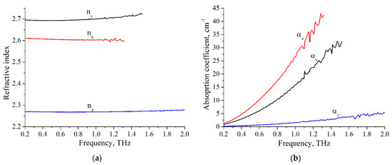
Figure 4.
Terahertz optical properties of LBO crystal for three axes at room temperature: (a) refractive index; (b) absorption coefficient.
With the help of the proposed method, we were able to measure the temperature dependence of the terahertz optical properties of the crystal for all three axes. The results of the refractive index at a frequency of 1 THz are presented in Figure 5. As can be seen from the figure, the refractive index decreases with cooling by 0.24, 0.17, and 0.02 for the optical axes x, y, and z, respectively. We used temperature-dependent expansion coefficients from [32] to adjust for temperature-related changes in the thickness of the samples. The LBO crystal has a positive expansion coefficient (ranging from 60.4 × 10⁻⁶ K−1 at room temperature to 11.5 × 10⁻⁶ K−1 at the liquid nitrogen temperature) along the a-axis; therefore, the a-cut sample shrank down to 2050 μm after cooling. Due to the negative expansion coefficient (ranging from −49.5 × 10⁻⁶ K−1 at room temperature to −11.6 × 10⁻⁶ K−1 at the liquid nitrogen temperature) for the c-axis, the c-cut sample expanded up to 2082 μm. As both samples allowed for the measurement of optical properties for the z-axis, we were able to crosscheck the results, which agreed well within the measurement uncertainty.
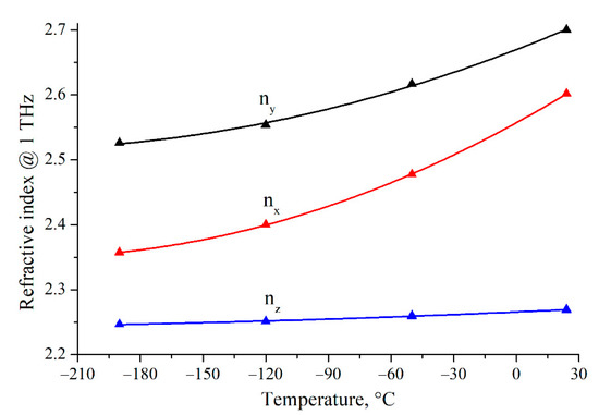
Figure 5.
Temperature dependence of the refractive index at a frequency of 1 THz of LBO crystal for three optical axes. Symbols represent measured values; lines represent the polynomial fit of the second order.
5. Discussion
The main advantage of the suggested and demonstrated method is that it does not require the rotation of a sample to align its axis along the polarization of terahertz radiation. It is especially useful for samples placed in a cryostat, a heating cell, or any isolated chamber. Properties for both axes of the sample can be measured during one cycle of heating or cooling using this method. A setup with two apertures also helps perform reference measurements without removing the sample. This improves the measurement speed, suppresses the effects of long-term drift in the system, and eliminates the systematic errors associated with repositioning the sample and its holder. The only drawback of the method seems to be losing about 6 dB of the terahertz signal. It occurs because a polarizer is used to rotate the polarization of generated terahertz radiation by an angle of 45° and the electro-optic detection sensitivity is lower for terahertz radiation that is polarized at 45°. However, this does not appear to be a significant deficiency considering that an exceptionally high dynamic range of a typical THz-TDS reaches more than 90 dB [33].
The method of finding the principle axes of the studied crystal is similar to a well-known method in optics. The polarizers need to have a high enough extinction ratio to obtain zero signal in a crossed configuration. It is especially important for high dynamic range THz-TDS systems. That is why we employ tandem polarizers based on metal-grids on carrying polymeric films that have a power extinction ratio of over 105:1 in the range of 0.2–2 THz. Two such polarizers are used to determine the principal axes of the crystal. However, there is an important distinction from the case of optics, as only one polarizer after the generator is necessary in further measurements to rotate the polarization of terahertz radiation impinging on the crystal. A second polarizer is not required, as the THz-TDS electro-optic detection system itself is inherently sensitive to the polarization of terahertz radiation.
6. Conclusions
We analyzed the sensitivity of electro-optic detection systems of terahertz time-domain spectrometers based on (110)-cut and (111)-cut zincblende crystals and its dependence on the polarization of terahertz and probe laser radiation. We found that the same sensitivity can be achieved for two orthogonal polarizations of terahertz radiation. For terahertz radiation linearly polarized at angles ±45° relative to the z-axis and the (−211)-axis for the cases of (110)-cut and (111)-cut detection crystals, respectively, the value of of the maximum sensitivity is achieved. This holds true for the probe laser radiation polarized at angles of 0° or 90°.
Based on the sensitivity analysis, we suggested a method for measuring terahertz properties for two principal optical axes of anisotropic crystals without optical activity. Under this approach, the sample under study is placed at an angle of 45° and terahertz polarization is aligned along its axes by rotating the polarizers. As the THz-TDS detection system has the same sensitivity for terahertz radiation that is polarized at ±45°, it is possible to consecutively measure two orthogonal polarization components without rotating the sample.
We demonstrated the applicability of the suggested method by measuring the refractive index and absorption coefficient along three optical axes of a lithium triborate crystal placed in a cryostat. At room temperature, the properties agreed well with our previous findings and results obtained by other research groups. As part of our work, we also studied the temperature dependence of the optical properties of the LBO crystal and showed that its refractive indices monotonically decreased with cooling without any peculiarities or crossings.
Author Contributions
Conceptualization, A.M. and N.N.; methodology, A.M., N.N. and V.A.; software, F.M.; validation, A.M., N.N. and V.A.; formal analysis, A.M.; investigation, A.M. and V.A.; resources, N.N. and V.A.; data curation, F.M. and A.M.; writing—original draft preparation, A.M.; writing—review and editing, A.M. and N.N.; visualization, F.M. and A.M.; supervision, A.M. and N.N.; project administration, A.M.; funding acquisition, A.M. All authors have read and agreed to the published version of the manuscript.
Funding
The work was funded by the Russian Science Foundation, project No. 19-72-00106.
Acknowledgments
The authors acknowledge the Shared Equipment Center “Spectroscopy and Optics” of the Institute of Automation and Electrometry SB RAS for the provided terahertz spectrometer.
Conflicts of Interest
The authors declare no conflict of interest.
References
- Dhillon, S.S.; Vitiello, M.S.; Linfield, E.H.; Davies, A.G.; Hoffmann, M.C.; Booske, J.; Paoloni, C.; Gensch, M.; Weightman, P.; Williams, G.P.; et al. The 2017 terahertz science and technology roadmap. J. Phys. D Appl. Phys. 2017, 50, 043001. [Google Scholar] [CrossRef]
- Zhang, X.; Shkurinov, A.; Zhang, Y. Extreme terahertz science. Nat. Photon 2017, 11, 16–18. [Google Scholar] [CrossRef]
- Mittleman, D.M. Perspective: Terahertz science and technology. J. Appl. Phys. 2017, 122, 230901. [Google Scholar] [CrossRef]
- Nagashima, T.; Tani, M.; Hangyo, M. Polarization-sensitive THz-TDS and its Application to Anisotropy Sensing. J. Infrared Millim. Terahertz Waves 2013, 34, 740–775. [Google Scholar] [CrossRef]
- Byrne, M.B.; Shaukat, M.U.; Cunningham, J.E.; Linfield, E.; Davies, A.G. Simultaneous measurement of orthogonal components of polarization in a free-space propagating terahertz signal using electro-optic detection. Appl. Phys. Lett. 2011, 98, 151104. [Google Scholar] [CrossRef]
- Sanjuan, F.; Gaborit, G.; Coutaz, J.-L. Full electro-optic terahertz time-domain spectrometer for polarimetric studies. Appl. Opt. 2018, 57, 6055–6060. [Google Scholar] [CrossRef]
- Zhao, G.; Savini, G.; Yu, Y.; Li, S.; Zhang, J.; Ade, P. A dual-port THz Time Domain Spectroscopy System optimized for recovery of a sample’s Jones matrix. Sci. Rep. 2019, 9, 1–9. [Google Scholar] [CrossRef]
- Zhang, L.; Zhong, H.; Deng, C.; Zhang, C.; Zhao, Y. Polarization sensitive terahertz time-domain spectroscopy for birefringent materials. Appl. Phys. Lett. 2009, 94, 211106. [Google Scholar] [CrossRef]
- Castro-Camus, E.; Lloyd-Hughes, J.; Johnston, M.; Fraser, M.D.; Tan, H.H.; Jagadish, C. Polarization-sensitive terahertz detection by multicontact photoconductive receivers. Appl. Phys. Lett. 2005, 86, 254102. [Google Scholar] [CrossRef]
- Makabe, H.; Hirota, Y.; Tani, M.; Hangyo, M. Polarization state measurement of terahertz electromagnetic radiation by three-contact photoconductive antenna. Opt. Express 2007, 15, 11650–11657. [Google Scholar] [CrossRef]
- Bulgarevich, D.S.; Watanabe, M.; Shiwa, M.; Niehues, G.; Nishizawa, S.; Tani, M. A polarization-sensitive 4-contact detector for terahertz time-domain spectroscopy. Opt. Express 2014, 22, 10332–10340. [Google Scholar] [CrossRef]
- Planken, P.C.M.; Nienhuys, H.-K.; Bakker, H.J.; Wenckebach, T. Measurement and calculation of the orientation dependence of terahertz pulse detection in ZnTe. J. Opt. Soc. Am. B 2001, 18, 313–317. [Google Scholar] [CrossRef]
- Van Der Valk, N.C.J.; Wenckebach, T.; Planken, P.C.M. Full mathematical description of electro-optic detection in optically isotropic crystals. J. Opt. Soc. Am. B 2004, 21, 622–631. [Google Scholar] [CrossRef]
- Yasumatsu, N.; Watanabe, S. Precise real-time polarization measurement of terahertz electromagnetic waves by a spinning electro-optic sensor. Rev. Sci. Instrum. 2012, 83, 23104. [Google Scholar] [CrossRef]
- Yasumatsu, N.; Wanatabe, S.; Watanabe, S. Robustness of electric field vector sensing of electromagnetic waves by analyzing crystal angle dependence of the electro-optic effect. J. Opt. Soc. Am. B 2013, 30, 2940–2951. [Google Scholar] [CrossRef]
- Xu, K.; Bayati, E.; Oguchi, K.; Watanabe, S.; Winebrenner, D.P.; Arbab, M.H. Terahertz time-domain polarimetry (THz-TDP) based on the spinning E-O sampling technique: Determination of precision and calibration. Opt. Express 2020, 28, 13482–13496. [Google Scholar] [CrossRef]
- Nemoto, N.; Higuchi, T.; Kanda, N.; Konishi, K.; Kuwata-Gonokami, M. Highly precise and accurate terahertz polarization measurements based on electro-optic sampling with polarization modulation of probe pulses. Opt. Express 2014, 22, 17915–17929. [Google Scholar] [CrossRef]
- Mosley, C.D.W.; Failla, M.; Prabhakaran, D.; Lloyd-Hughes, J. Terahertz spectroscopy of anisotropic materials using beams with rotatable polarization. Sci. Rep. 2017, 7, 12337. [Google Scholar] [CrossRef]
- Dong, H.; Gong, Y.; Paulose, V.; Hong, M. Polarization state and Mueller matrix measurements in terahertz-time domain spectroscopy. Opt. Commun. 2009, 282, 3671–3675. [Google Scholar] [CrossRef]
- Aschaffenburg, D.J.; Williams, M.R.C.; Talbayev, D.; Santavicca, D.F.; Prober, D.E.; Schmuttenmaer, C.A. Efficient measurement of broadband terahertz optical activity. Appl. Phys. Lett. 2012, 100, 241114. [Google Scholar] [CrossRef]
- George, D.K.; Stier, A.V.; Ellis, C.T.; McCombe, B.D.; Cerne, J.; Markelz, A.G. Terahertz magneto-optical polarization modulation spectroscopy. J. Opt. Soc. Am. B 2012, 29, 1406–1412. [Google Scholar] [CrossRef]
- Morris, C.M.; Aguilar, R.V.; Stier, A.V.; Armitage, N.P. Polarization modulation time-domain terahertz polarimetry. Opt. Express 2012, 20, 12303–12317. [Google Scholar] [CrossRef]
- Kokh, A.; Kononova, N.; Mennerat, G.; Villeval, P.; Durst, S.; Lupinski, D.; Vlezko, V.; Kokh, K. Growth of high quality large size LBO crystals for high energy second harmonic generation. J. Cryst. Growth 2010, 312, 1774–1778. [Google Scholar] [CrossRef]
- Kokh, A.; Vlezko, V.; Kokh, K.; Kononova, N.; Villeval, P.; Lupinski, D. Dynamic control over the heat field during LBO crystal growth by High temperature solution method. J. Cryst. Growth 2012, 360, 158–161. [Google Scholar] [CrossRef]
- Wang, C.-R.; Pan, Q.-K.; Chen, F.; Lanskii, G.; Nikolaev, N.; Mamrashev, A.; Andreev, Y.; Meshalkin, A. Phase-matching in KTP crystal for THz wave generation at room temperature and 81 K. Infrared Phys. Technol. 2019, 97, 1–5. [Google Scholar] [CrossRef]
- Mamrashev, A.A.; Nikolaev, N.A.; Kuznetsov, S.A.; Gelfand, A.V. Broadband Metal-Grid Polarizers on Polymeric Films for Terahertz Applications. AIP Conf. Proc. 2020, 2300, 020083. [Google Scholar] [CrossRef]
- Boer, J.H.W.G.D.; Kroesen, G.M.W.; de Zeeuw, W.; de Hoog, F.J. Improved polarizer in the infrared: Two wire-grid polarizers in tandem. Opt. Lett. 1995, 20, 800–802. [Google Scholar] [CrossRef]
- Andreev, Y.M.; Kokh, A.; Kokh, K.; Lanskii, G.; Litvinenko, K.; Mamrashev, A.; Molloy, J.; Murdin, B.; Naftaly, M.; Nikolaev, N.; et al. Observation of a different birefringence order at optical and THz frequencies in LBO crystal. Opt. Mater. 2017, 66, 94–97. [Google Scholar] [CrossRef]
- Nikolaev, N.; Andreev, Y.M.; Kononova, N.G.; Mamrashev, A.; Antsygin, V.D.; Kokh, K.; Kokh, A.; Losev, V.F.; Potaturkin, O. Terahertz optical properties of LBO crystal upon cooling to liquid nitrogen temperature. Quantum Electron. 2018, 48, 19–21. [Google Scholar] [CrossRef]
- Song, K.; Tian, Z.; Zhang, W.; Wang, M. Temperature-dependent birefringence of lithium triborate, LBO in the THz regime. Sci. Rep. 2017, 7, 1–7. [Google Scholar] [CrossRef]
- Bernerd, C.; Segonds, P.; Debray, J.; Roux, J.-F.; Herault, E.; Coutaz, J.-L.; Shoji, I.; Minamide, H.; Ito, H.; Lupinski, D.; et al. Evaluation of eight nonlinear crystals for phase-matched Terahertz second-order difference-frequency generation at room temperature. Opt. Mater. Express 2020, 10, 561. [Google Scholar] [CrossRef]
- Grechin, S.G.; Zuev, A.V.; Kokh, A.; Moiseev, N.V.; Popov, P.; Sidorov, A.; Fokin, A.S. Thermophysical parameters of the LBO crystal. Quantum Electron. 2010, 40, 509–512. [Google Scholar] [CrossRef]
- Vieweg, N.; Rettich, F.; Deninger, A.; Roehle, H.; Dietz, R.; Göbel, T.; Schell, M. Terahertz-time domain spectrometer with 90 dB peak dynamic range. J. Infrared Millim. Terahertz Waves 2014, 35, 823–832. [Google Scholar] [CrossRef]
Publisher’s Note: MDPI stays neutral with regard to jurisdictional claims in published maps and institutional affiliations. |
© 2021 by the authors. Licensee MDPI, Basel, Switzerland. This article is an open access article distributed under the terms and conditions of the Creative Commons Attribution (CC BY) license (https://creativecommons.org/licenses/by/4.0/).