Skip to Content
PhotonicsPhotonics
  • Editor’s Choice
  • Article
  • Open Access

4 December 2020

Scaling of Beam Collective Effects with Bunch Charge in the CompactLight Free-Electron Laser

,
,
,
,
,
,
,
,
1
Elettra–Sincrotrone Trieste S.C.p.A., 34149 Trieste, Italy
2
Department of Physics, University of Trieste, 34100 Trieste, Italy
3
European Organization for Nuclear Research, CH-1211 Geneva, Switzerland
4
Helsinki Institute of Physics, Helsinki University, FIN-00014 Helsinki, Finland
This article belongs to the Special Issue Photonics, Optics and Laser Technology

Abstract

The CompactLight European consortium is designing a state-of-the-art X-ray free-electron laser driven by radiofrequency X-band technology. Rooted in experimental data on photo-injector performance in the recent literature, this study estimates analytically and numerically the performance of the CompactLight delivery system for bunch charges in the range 75–300 pC. Space-charge forces in the injector, linac transverse wakefield, and coherent synchrotron radiation in bunch compressors are all taken into account. The study confirms efficient lasing in the soft X-rays regime with pulse energies up to hundreds of microjoules at repetition rates as high as 1 kHz.

1. Introduction

Free-electron lasers (FELs) can deliver high-intensity photon beams of unprecedented brilliance and coherence [1], providing large potential for the science of matter [2]. Advances in several fields which drive new technological solutions for future FELs have been made over the last decade [3]. To mention a few, the construction of ultra-low emittance and high repetition rate photo-injectors, high gradient linacs, advanced undulator concepts, and schemes of electron beam manipulation for a more accurate preservation of the 6-dimensional normalized beam brightness along the delivery system. These developments aim not only at pushing FELs to the frontier of even higher peak intensity, higher average power, and full coherence, but also at reducing their cost and size, thus making an FEL a more affordable investment.
CompactLight [4] is a consortium of 26 different institutions around the world, financed by the European Union to design a compact and cost-effective X-band-driven FEL at soft and hard X-ray photon energies [5,6,7,8,9,10]. The CompactLight FEL foresees the simultaneous operation of a soft and a hard X-ray line, and repetition rates in the range 0.1–1 kHz. In its baseline design, the high brightness electron beam is generated in a C-band photo-injector, and boosted in energy by a high gradient, normal conducting X-band linac. A nominal bunch charge of 75 pC has been chosen to ensure simultaneously: (i) transverse emittances at the diffraction limit in the x-rays, (ii) femtosecond bunch duration and (iii) kA peak current in the undulator, which all together ensure FEL power saturation within 20 m. Such low charge also favors the preservation of the slice and projected transverse emittance in the presence of beam collective effects. These include space-charge forces in the photo-injector, geometric transverse wakefields in the accelerating structures, and coherent synchrotron radiation (CSR) in the magnetic compressors.
Figure 1 shows the normalized 6-dimensional electron beam brightness of the most recent existing and planned short-wavelength FEL facilities. The brightness of each facility is calculated from projected and core-slice beam parameters. The CompactLight accelerator design is well on the path of state-of-the-art accelerators. By virtue of this and of an advanced undulator design based on superconducting insertion device, the CompactLight FEL parameters meet a state-of-the-art peak brilliance of ~1031–1033 ph/sec/mm2/mrad2/0.1%bw at the source, in the photon energy range 0.25–16 keV. The number of photons per pulse, however, is smaller than the one produced at other, less compact X-ray FELs in the same photon energy range. This motivates the study of higher bunch charges in CompactLight in order to increase the pulse energy from present < 100 µJ up to several 100′s µJ, especially in the soft X-ray range. In this study, the final bunch peak current is kept fixed at its nominal value, which keeps both the FEL saturation power and the saturation length nearly constant. Consequently, the bunch charge is increased at the expense of the FEL pulse duration, which is proportional to the electron bunch duration in self-amplified spontaneous emission (SASE) [11,12]. In principle, this would allow us to scale linearly the expected FEL pulse energy with charge. However, as will be shown later on, a higher bunch charge is associated with larger slice and projected transverse emittances, which might imply some reduction of the output pulse energy (power) respect to a simple linear scaling.
Figure 1. 6-dimensional normalized electron beam brightness from projected and core-slice parameters (left, adapted from [3]), and peak photon brilliance (right) for existing and planned short-wavelength FELs. The CompactLight electron beam brightness (filled markers) and brilliance are reported for the nominal bunch charge of 75 pC.
We anticipate that a higher charge is inevitably related to a larger slice emittance from the photo-injector because of stronger space-charge forces. In an optimized photo-injector, the bunch slices are almost perfectly aligned in the transverse phase space, so that the slice emittance value is basically the same of the projected emittance. In the main linac, beam collective effects such as geometric short-range wakefields and CSR, both proportional to the bunch charge, are expected to be stronger too, with consequent degradation of the beam final projected emittance. In this case, however, and for beam gymnastics far enough from full compression, the slice emittance is expected not to be degraded.
The CompactLight layout and its nominal parameters are depicted in Section 2. To quantify the electron beam brightness along the accelerator at charges > 75 pC, a scaling law of the transverse emittance with bunch charge and peak current from optimized photo-injectors is introduced in Section 3. A collection of experimental data from the recent literature, though homogeneous neither in quality nor in methods, is used to illustrate the approximate validity of the “invariant beam envelope” model in the space-charge-dominated regime [13,14,15]. We thus rely on the model for an approximate but still realistic prediction of beam emittance at higher charges. Well-established analytical expressions are then adopted in Section 4 to evaluate the final projected emittance in the presence of single-bunch beam-break-up (BBU) [16] and CSR tail-head instabilities [17]. In the last few years, a systematic benchmarking of CSR-induced emittance growth at high brightness linac-driven FELs has been carried out [18,19,20,21,22,23], which allows us to adopt analytical models for this collective effect with a high confidence level [24]. On the contrary, some more limited attention has been given to validation of the theoretical model of BBU [25]. For this reason, a comparison of well-known analytical expressions for the BBU-induced emittance growth [26] with particle tracking runs is presented to reinforce our expectations. Multi-bunch effects due to long-range wakefields in the linac are not considered in this study, since the experience gained over recent years has shown that techniques such as damping and detuning of the high-order modes can effectively mitigate their impact [27,28]. Finally, Section 5 outlooks the SASE FEL performance at high charge on the basis of the estimated electron beam parameters at the undulator; predictions are based on classical fitting models for SASE [29,30]. We reach conclusions in Section 6.

2. The Compact Light Free-Electron Laser

In its baseline design, the CompactLight linac consists of a Cu-cathode, C-band (6 GHz) photo-injector that embeds X-band (12 GHz) cavities for boosting the beam energy up to ~300 MeV, and a short Ka-band (36 GHz) cavity for linearization of magnetic bunch length compression [31,32]. Compression happens in two stages: the two four-dipole chicanes (BC1 and BC2) correspond to the beam energy of approximately 300 MeV or 2 GeV in the case when the linac is run at the repetition rate of 0.1 kHz. A laser heater is installed in the injector to mitigate the microbunching instability [33,34]. A full X-band linac boosts the beam energy to the maximum value of 5.5 GeV, see Figure 2-top plot. An upgrade of the radiofrequency (RF) distribution system (Figure 2-middle plot) would increase the repetition rate of the soft X-ray FEL up to 1 kHz. Such higher rate is obtained at the expense of the peak accelerating gradient (for a constant average RF power), thus of the maximum beam energy. A second upgrade, sketched in Figure 2-bottom plot, foresees the simultaneous operation of a soft (SX) and a hard X-ray (HX) FEL line by fast switching systems located at an intermediate position along the linac and at its end. This upgrade also foresees external seeding schemes in SX and self-seeding in HX to improve the FEL brilliance respect to SASE. Table 1 summarizes the design single pulse SASE FEL performance at the nominal bunch charge of 75 pC. The electron beam parameters adopted in this study are listed in Table 2.
Figure 2. CompactLight layout (not to scale) for the baseline and upgraded footprints, see text for details.
Table 1. CompactLight FEL parameters at the bunch charge of 75 pC.
Table 2. Nominal electron beam parameters adopted in this study.
For modeling, we consider the variation of beam energy, peak current, and linear optics along the accelerator as in Figure 3. One should note that the SX operation at 0.1 kHz foresees beam extraction from the main linac at the intermediate energy of 2 GeV. Since different repetition rates correspond to different beam energies along the linac, the quadrupole magnet strength is varied to keep the betatron functions substantially unchanged. Among several intermediate configurations, the two extreme scenarios of lowest and highest peak current, 0.35 and 4.5 kA, are considered in the remaining of this article. The lowest (highest) peak current represents the minimum value compatible with FEL power saturation within 20 m, at the lowest (highest) photon energy of 0.25 (16) keV.
Figure 3. From top to bottom, electron beam mean energy, rms bunch duration, betatron, and dispersion functions along the CompactLight accelerator. Soft and hard X-ray operation at repetition rates in the 0.1–1 kHz range is illustrated. Bunch durations correspond to the nominal bunch charge of 75 pC and to the final peak current of 0.35 kA and 4.5 kA. The soft X-ray operation at 0.1 kHz foresees beam extraction from the main linac at the intermediate energy of 2 GeV.

3. Space-Charge Force in the RF Photo-Injector

3.1. Model of Invariant Beam Envelope

The transverse emittance at the exit of an optimized RF photo-injector depends on the radial component of the time-varying electric field, the nonlinear magnetic field component of the solenoid field external to the gun, the intrinsic (or thermal) emittance, and the space-charge-dominated emittance [35]. In the following, we will neglect the former three contributions and will assume a symmetric charge distribution in the transverse plane. This approximation is valid as long as the beam transverse sizes are much smaller than the gun cell iris radius, the beam is well aligned to the gun electric axis, and the emittance at the injector exit is weakly affected by its thermal value. The simplified picture allows us to describe the particles motion as laminar, i.e., particle trajectories do not cross. Hence, the equation of motion for the cylindrically symmetric beam envelope becomes [36]:
σ u + σ u β γ β γ + K σ u = 2 I I 0 β γ 3 σ u f σ u β γ σ z
where u = x, y, prime indicates the derivative regarding the longitudinal coordinate s, K = 2 π / β u 2 is the square of the betatron wave number in the presence of linear static externally applied forces, I is the bunch peak current, I0 = 17,045 A is the Alfven current, β and γ are the Lorentz relativistic factor for velocity and energy respectively, and σz is the root-mean-square (RMS) bunch length.
We now assume that the photo-injector is optimized in terms of laser, RF, and geometric parameters, so that the normalized transverse emittance is minimized at ultra-relativistic beam energies (>100 MeV), and in accordance to a set of boundary conditions regarding, for example, bunch charge (>50 pC), bunch duration (>1 ps rms) and peak current (>10 A). For the CompactLight case study, this optimization process resulted in the simulation of beam parameters in Table 2 [7,37]. Next, we consider a variation of the bunch charge, but imposing that the beam envelope has the same transverse oscillation phase (same wave number) than at the nominal charge, so that we keep the whole injector beam line setting unchanged. This requires that the driving term in the r.h.s. of Equation (1), which represents a defocusing space-charge force, remain constant. Following [36], we rewrite the peak current in terms of a form factor dependent on the distribution, I = g Q c / σ z , and the space-charge term as:
κ s c = 2 I I 0 β γ 3 σ u f σ u β γ σ z = g 2 c I 0 β 2 γ 3 f σ u β γ σ z Q σ u 2 σ z
If the distribution shape (g) and the transverse-to-longitudinal aspect ratio (f) are kept the same when the charge is varied, then Equation (2) implies
Q σ u 2 σ z = c o n s t .
In the presence of almost linear space-charge force in the three spatial dimensions, we get σ i Q 1 / 3 with i = x, y, z. Since a constant focusing force implies unchanged betatron function, and recalling that σ u = ε u β u , we find:
ε n , u μ m   r a d a × Q n C 2 / 3
and a 1 in proper units. Equation (3) also implies:
ε n , u μ m   r a d b × I k A
with b 8 in proper units.
An alternative scaling law, still consistent with Equation (3), is obtained by forcing σ z = c o n s t . , for example as given by a proper laser longitudinal shaping. In this case, σ u   Q 1 / 2 , and we obtain:
ε n , u μ m   r a d c × Q n C
where c 1 in proper units, and Equation (5) still holds.
The adoption of practical units in Equations (4) and (5) is consistent with 3-dimensional particle-in-cell simulation studies at Q < 1 nC [35]. A lower bound at around Q ≈ 50 pC for the validity of such scaling laws can be envisaged, in correspondence of which the thermal emittance starts dominating the total emittance. The numerical coefficients a, b, c were anticipated based on a fit to experimental data, as shown in the next section.

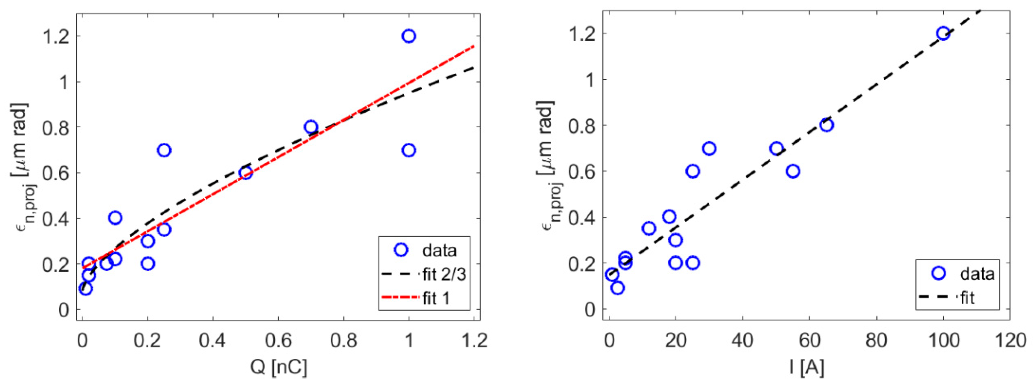
3.2. Experimental Data and Emittance Scaling

The transverse projected emittance measured at the exit of high brightness RF photo-injectors [18,19,38,39,40,41] is reported in Figure 4 as function of the bunch charge and the core peak current. All emittance values refer to beam energies > 90 MeV, at which the space-charge force is expected to be largely reduced. When the emittance for both planes is available from the literature, the value in Figure 4 is the geometric mean of the two. The figure collects a variety of photo-injector data as for geometry (single and multi-cells, single and symmetric input couplers, etc.), cathode material (Cu, Cs2Te), gun accelerating gradient (80–120 MV/m), transverse and longitudinal laser pulse shaping and sizes, vacuum pressure, etc. Despite the non-homogeneity of the collected data, we compare them with the theoretical model depicted by Equations (4)–(6). A numerical fit is applied by including a series of fractional powers of the charge and current (1/3, 1/2, 2/3, 1, but only 2/3 and 1 shown). We preliminary conclude that without the ambition of identifying a universal and accurate scaling of the normalized emittance with charge and current at modern photo-injectors, we can consider Equations (4) and (5) as an approximate but practical rule-of-thumb. The fit predicts a non-zero emittance when Q → 0 because Equations (4) and (5) only try to capture the contribution of space-charge forces to the emittance. In the limit of zero current, a residual thermal emittance shows up. On the contrary, Equation (6) is not able to capture very low emittance values when the bunch charge shrinks to less than 0.1 nC.
Figure 4. Normalized transverse projected emittance as function of the bunch charge (left) and peak current (right), and best fit from Equation (4) (left, “fit 2/3”), Equation (5) (left, “fit 1”) and Equation (6) (right). Data collected from [18,19,38,39,40,41].
We now consider a 2 and 4-fold increase of the CompactLight bunch charge, i.e., 150 and 300 pC. According to Equation (4), the beam transverse emittance at the photo-injector exit grows by a factor ~1.6 and ~2.5, respectively. The diffraction limit at the shortest wavelengths of the soft X-ray line, for the beam energy of 1 and 2 GeV (see Table 1), specifies a normalized emittance < 0.2 µm rad. This is approximately met at the charge of 150 pC, but it is exceeded by a factor ~2 at 300 pC, which suggests some less efficient lasing in this case.
Table 3 summarizes the beam parameters at 75 pC and the scaled ones at higher charges. The emittance and the peak current at the photo-injector exit are assumed to be the same for low and high repetition rate, i.e., an accelerating gradient lower than optimum is adopted in the scenario of low repetition rate. The total compression factor is calculated as the ratio of final and initial peak current in the bunch core, and by keeping the final peak current at the nominal value of 0.35 kA at 1 GeV, and 4.5 kA at 2 GeV. The final bunch duration is calculated by first calculating the duration at the injector exit according to the scaling ~Q1/3 (implied by Equations (4) and (5)), then by dividing it by the compression factor.
Table 3. CompactLight electron beam parameters at the injector exit (~100 MeV) at the nominal bunch charge of 75 pC (from simulations) and at higher charges (from scaling with Equations (4) and (5). Final beam energy, duration, compression factor, and final peak current are reported for the 3 scenarios in Figure 3.

4. Beam Collective Effects in the Main Linac

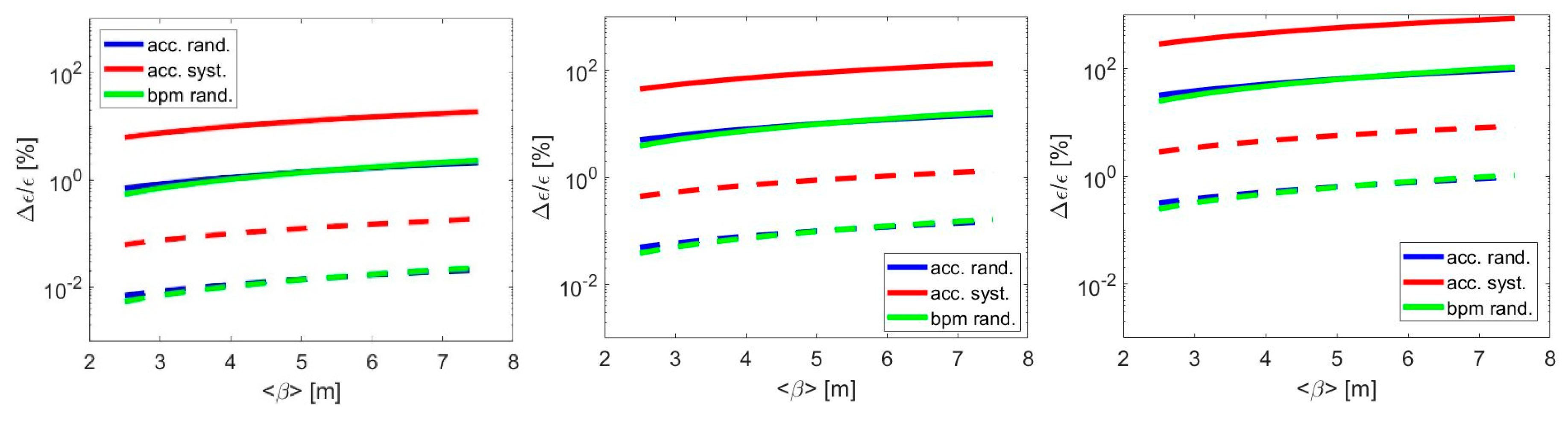
4.1. Coherent Synchrotron Radiation

The transverse CSR tail-head instability causes misalignment of bunch slices in the bend-plane phase space, thus projected emittance growth. This receives the largest contribution from CSR emission in the second half of the 4-dipoles chicane used for bunch length compression, and specifically from the 3rd dipole magnet [42,43]. A small betatron function is recommended at that location to increase the beam divergence, and therefore minimize the effect of the CSR angular kick. Table 4 recalls the CompactLight magnetic compressor parameters, used in the remainder of this article.
Table 4. CompactLight BC1 and BC2 parameters for the evaluation of the CSR effect on emittance. For other beam parameters, see Table 3.
The importance of 3-dimensional effects in the CSR emission have recently been pointed out with analytical, numerical, and experimental benchmarking at the FERMI FEL facility [23,44]. The studies have shown that 1-dimensional approximations may over-estimate the emittance growth when the beam is approaching full compression. A revisited analytical theory [24] has improved further the estimations presented in [23], by calculating the emittance growth as due to the longitudinal (Equation (7)) and transverse (Equation (8)) component of the CSR field:
Δ ε n , L = 7.5 × 10 3 β γ N r e L b 2 R 5 3 σ z 4 3 2
Δ ε n , T = 2.5 × 10 2 β γ N r e L b R σ z 2
where β is the average bend-plane betatron function in the dipole magnet, γ the relativistic Lorenz factor for the beam mean energy, N the number of electrons per bunch, re the electron classical radius, Lb the dipole arclength, R the curvature radius and σz the RMS bunch length.
Figure 5 shows the horizontal projected normalized emittance growth, calculated with Equations (7) and (8), as due only to the 3rd dipole magnet of BC1 and BC2. A similar calculation of the contributions from the other 3 dipoles indicates that the CSR effect in the 3rd dipole is approximately 75% of the total. For each compressor, the contribution from the longitudinal (suffix L in the legend) and transverse (suffix T in the legend) CSR field in steady-state approximation is illustrated. The calculation is repeated for bunch charges of 75, 150, and 300 pC (from left to right plot). The total of 4 contributions to the total emittance growth is repeated in each plot for the 3 CompactLight configurations devoted to lasing in the hard x-rays at 0.1 kHz, in the soft x-rays at 0.1 kHz, and in the soft x-rays at 1 kHz (see beam energy and bunch duration in Figure 3). The solid line in each plot (right vertical axis) guides the eye to the final bunch peak current in each configuration.
Figure 5. Horizontal normalized projected emittance growth from CSR longitudinal (L) and transverse (T) field in BC1 and BC2, for the bunch charge of 75 (left), 150 (middle) and 300 pC (right). See text for details.

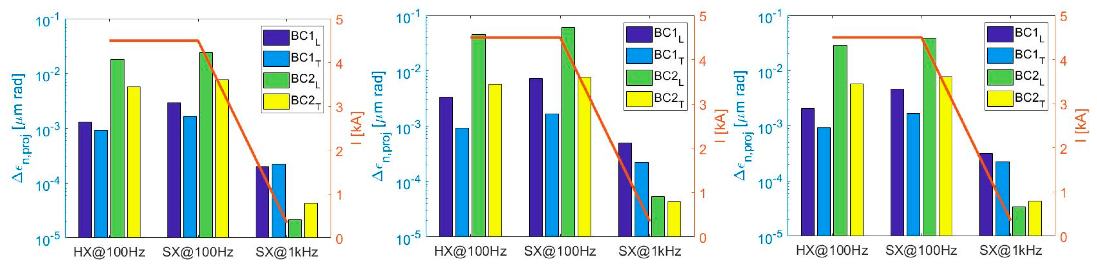
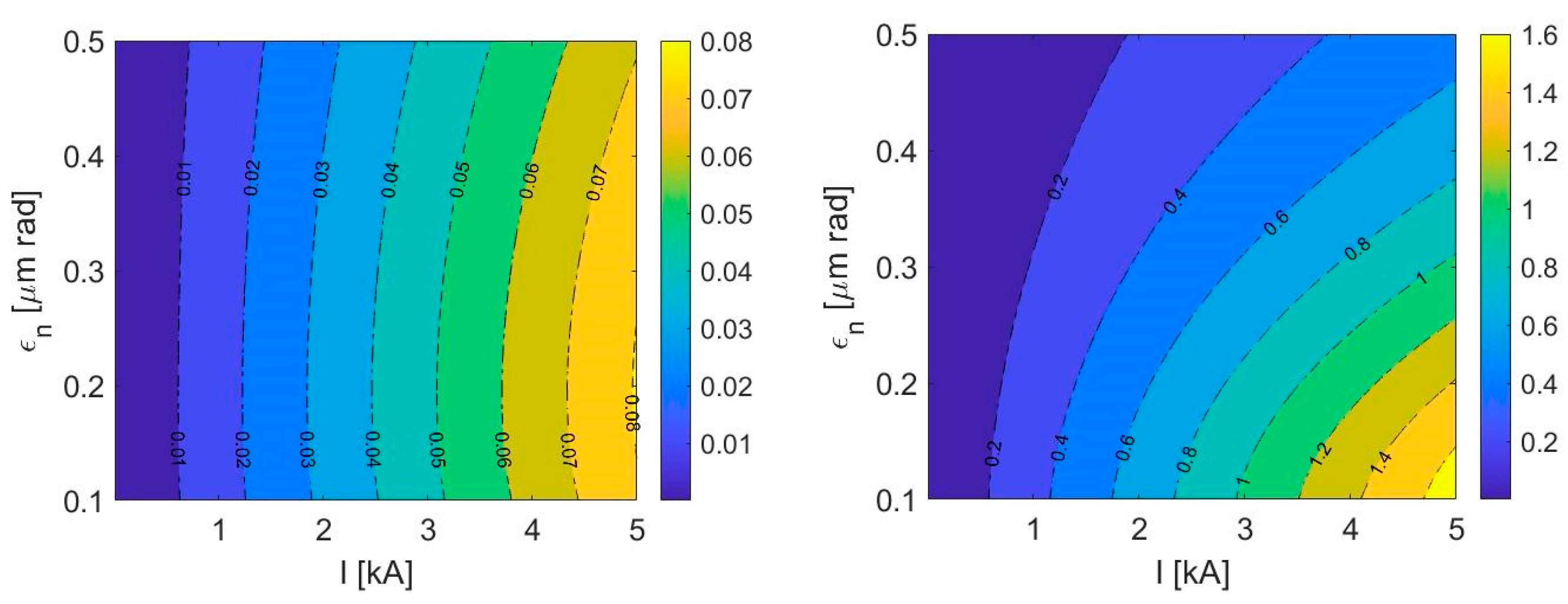
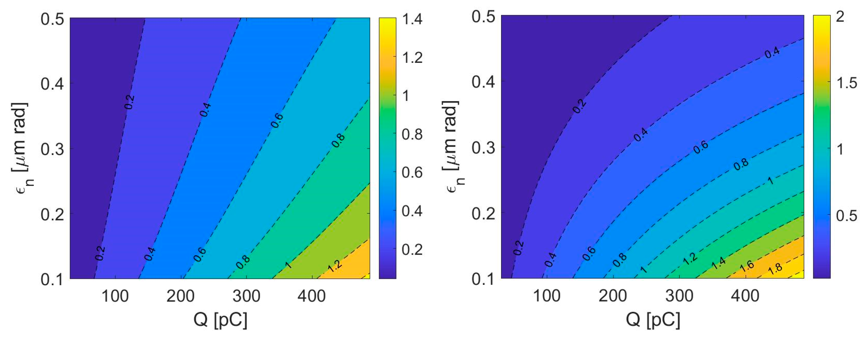
4.2. Single-Bunch Beam Break-Up

The single-bunch BBU instability is the misalignment of trailing bunch slices in the transverse phase space, due to the geometric wakefield excited by the bunch head in accelerating structures. At the lowest order of dipole approximation, the wake is excited only if the bunch head is misaligned regarding the electric axis of the structure. Since the structures have cylindrical symmetry, the instability can affect the horizontal and the vertical plane. Analytic expressions for the projected normalized emittance growth [26] can be used to estimate the effect under different scenarios of trajectory mishandling, i.e., randomly misaligned accelerating structures, randomly misaligned structures but with a systematic error associated with two consecutive structures, and randomly misaligned beam position monitors (BPMs). The latter option describes the one-to-one trajectory correction in the assumption that each BPM is close to a quadrupole magnet, so that the beam is centered in the magnets but misaligned in adjacent structures. We assume a weak dependence of the average betatron function on beam energy ( β γ α ,   with   α < 0.01 ), a linear increase of the beam energy with the linac distance ( γ s ), and a 3-sigma cutoff Gaussian distribution of misalignments ( Δ s t r , Δ B P M ). The expressions for the three scenarios depicted above are:
Δ ε n , r a n Δ s t r 2 π ε 0 r e N w T 2 σ z 2 L s t r 2 β ¯ 2 α Δ γ s t r γ f γ i α 1
Δ ε n , s y s Δ s t r 2 π ε 0 r e N w T 2 σ z 2 L c e l l L s t r β ¯ 4 α Δ γ s t r γ f γ i 2 α 1
Δ ε n , b p m Δ b p m 2 π ε 0 r e N w T 2 σ z 2 c o s Δ μ / 2 sin 3 Δ μ / 2 L c e l l 2 L s t r 16 α Δ γ s t r γ f γ i 2 α 1
Here, ε 0 is the electric permittivity of vacuum, re the electron classical radius, N the number of electrons per bunch, Lstr the length of a single accelerating structure, Lcell the length of the linac focusing-defocusing (FODO) cell, and Δµ the betatron phase advance per cell (this is calculated from the average betatron function per cell and the cell length). The lattice is assumed to be flexible enough to vary the average betatron function in the range 2.5–6.5 m, consistently with the optics in Figure 3. The transverse wake function per unit length in V/C/m2 of the CompactLight X-band structure is estimated according to [45] for an average inner iris radius of 3.5 mm:
w T = 2.574 × 10 17 1 1 + 2 σ z s 1 e x p 2 σ z s 1
with s1 = 268 µm defined by the cell geometry.
The study of the BBU is applied to the scenario of SX at 1 kHz repetition rate, specifically to the lowest final beam energy (1 GeV) and longest final bunch duration (~220 fs rms): they both determine the largest emittance growth for a given set of alignment errors. Any other scenario, for example at lower repetition rate (i.e., higher beam energy) or shorter duration (i.e., higher peak current) will be less affected by the transverse wakefield. Since the model only applies to a fixed FODO cell length and to constant bunch duration, the calculation is limited to the last linac section, i.e., the section following BC2. Although BBU can be stronger for longer bunches, such as before compression and at lower beam energies, the final linac section is far longer than all other upstream sections, and is characterized by the longest cell length (4 m vs. 1 m and 2 m at lower energies). For similar beam-to-linac misalignment along the accelerator, that linac is expected to be the main contributor to the total BBU-induced emittance growth.
Table 5 summarizes the parameters adopted for the BBU study. The random RMS lateral misalignment of accelerating structures is assumed to be ≤100 µm before any correction. Smaller values can be interpreted as the result of beam-based alignment procedures aimed at minimizing the BBU instability. To validate the analytical model, a preliminary benchmark with the PLACET code [46] is done, and shown in Figure 6. The final relative emittance growth (either in x or y plane) from the code and from Equation (9) is compared in a wide range of rms misalignments (10–100 µm rms), average betatron functions (3–5 m) and bunch charges (75–300 pC). The PLACET predictions are the average of 10 errors seeds per RMS misalignment, per betatron phase advance along the FODO cell, and per bunch charge. The maximum discrepancy between tracking and theory over all the configurations is ~10% when a relative emittance growth ≤50% (and up to ~0.2 µm) is considered. For larger effects (emittance growth exceeding ~0.2 µm), the discrepancy becomes larger, up to ~25%. This might be explained by the fact that Equation (9), and similarly Equations (10) and (11), were derived in the approximation Δ ε / ε 1 . Given that Δ ε / ε > 50 % describes the case in which the bunch tail is offset respect to the head axis by more than one sigma of the (unperturbed) beam size, this scenario is taken as the tolerance of the BBU effect for lasing [47]. In summary, the substantial agreement of the analytical and the numerical results demonstrates that the analysis is able to capture the physics of the instability in the range of CompactLight parameters.
Table 5. CompactLight linac parameters for the evaluation of the BBU instability. For other beam parameters at the various bunch charges, see Table 3.
Figure 6. Percent projected emittance growth due to BBU through the linac downstream BC2 as function of the random rms misalignment of accelerating structures and average betatron function, for the bunch charge of (from left to right) 75, 150, and 300 pC. Beam and linac parameters are in Table 3 and Table 5. The red dots and labels refer to PLACET results. Note the color scale spans over 2 orders of magnitude from low to high charge.
As a next step in the analysis of the BBU, the contribution to the emittance growth by the 3 distinct configurations of misalignment depicted by Equations (9)–(11) is investigated, and shown in Figure 7. For each bunch charge, an RMS misalignment of accelerating structures and BPMs of 100 µm and 10 µm is assumed. These represent, respectively, an uncorrected trajectory in the presence of static alignment errors, and an improved relative alignment as obtained, for example, through BBA dispersion-free and wakefield-free steering algorithms [48].
Figure 7. Projected normalized relative emittance growth due to BBU along the linac downstream BC2 vs. average betatron function, at the bunch charge of (from left to right) 75, 150, and 300 pC. In each plot, solid (dashed) lines are for 100 µm (10 µm) RMS misalignment of accelerating structures and BPMs.

5. Free-Electron Laser

5.1. Peak Brilliance

In this section, the dependence of photon brilliance and pulse energy on beam emittance and bunch charge is analyzed. We will consider the SASE scheme, which is planned both in the baseline and the upgraded designs, in the following discussion. An expression for the brilliance (in practical units) which assumes uniform beam parameters along the electron bunch, and thereby slice and projected emittance to coincide, is given in [49,50]:
B p h 4.5 × 10 30 I kA × E GeV λ nm × δ   # photons / sec / mm 2 / mrad 2 / 0.1 % bw
where δ (typically close to unity or a fraction of it) is a correction factor taking into account transverse and longitudinal coherence, and which contains information on the beam emittance and peak current through the FEL gain length   L g or, equivalently, the FEL (Pierce) parameter [12].
We computed Equation (13) by modifying L g [29,30] which, in our range of parameters, are dominated by the beam non-zero transverse emittance and relative slice energy spread, so that L g , 3 D L g . Preliminary start-to-end simulations indicate that the core-slice energy spread at the undulator entrance, for the 75 pC bunch charge, is in the range 0.01–0.04% (RMS value), depending on the beam energy and compression factor. Here, we realistically assume that it is equal or even smaller at higher bunch charges, so that we can disentangle its effect on the brilliance from the one of the projected emittance, which is discussed below. The assumption is motivated by the fact that higher charges are obtained while keeping the 3-dimensional charge density constant during the photo-emission process (see Equation (3)), so that the initial uncorrelated energy spread is expected not to vary substantially. The final energy spread is proportional to the initial one by the compression factor. Since we keep the final peak current constant, the higher the bunch charge is, the lower the compression factor is (see Table 3), which ends up in a possibly even lower energy spread at the undulator.
Equation (13) is calculated for the CompactLight FEL and shown in Figure 8 as function of the beam slice emittance and peak current at the undulator entrance, in units of 1033 #photons/sec/mm2/mrad2/0.1%bw, for the highest photon energy in SX (2 keV) and HX (16 keV), and the electron beam energy of 2 and 5.5 GeV respectively. The gain length spans over 1–1.5 m, and power saturation is obtained in less than 20 m of a superconducting undulator for planar polarized emission (13 mm magnetic period and 0.7 T rms magnetic field at 4 mm full gap).
Figure 8. FEL peak brilliance (Equation (13)) with 3-D corrections, as function of the beam normalized slice emittance and peak current at the undulator, in units of 1033 #photons/sec/mm2/mrad2/0.1%bw, at the photon energy of 2 keV (left) and 16 keV (right). The electron beam energy is, respectively, 2 and 5.5 GeV.
We now show that the additional brilliance degradation due to the increase of the projected emittance scales at most linearly with the ratio of projected and slice emittance. We first observe that misalignment of bunch slices in the transverse phase space as induced by either BBU or CSR, translates into an enlarged projected emittance [51] ε n , p r ε n , s l 1 + β u γ θ coll 2 ε n , s l , where ε n , s l is the unperturbed emittance, β u the average betatron function along the undulator, and θ coll 2 the rms spread in angular divergence of the slice centroid. The lack of radiation overlap due to emission by misaligned slices leads to a longer gain length [52]:
L g , 3 D c o l l L g , 3 D 1 + α θ coll 2 L g , 3 D 1 + 2 L g , 3 D β u Δ ε n γ λ L g , 3 D 1 + L g , 3 D 2 π β u Δ ε n ε n , s l L g , 3 D 1 + χ Δ ε n ε n , s l
where we substituted α L g , 3 D / λ [53], θ coll 2 is expressed as function of the emittance growth Δ ε n = ε n , p r ε n , s l in the regime Δ ε n / ε n , s l 1 , and the unperturbed emittance is close to the diffraction limit, ε n , s l γ λ / 4 π . In practical situations, χ < 0.1 . Since B p h ~   δ   ~   ln L g , 3 D ε n , s l 11 / 6   [49], the impact of collective effects on B p h can be estimated by replacing L g , 3 D L g , 3 D c o l l and ε n , s l ε n , p r which, after some math, gives:
B p h c o l l B p h 1 + β u γ θ coll 2 ε n , s l 11 / 12 1 + l n 1 + χ Δ ε n ε n , s l l n L g , 3 D B p h 1 2 Δ ε n ε n , s l

5.2. Pulse Energy and Transverse Coherence

Figure 9 shows the FEL pulse energy in mJ as function of the beam slice emittance and the bunch charge, for the same photon energies, electron beam energies, and undulator parameters of Figure 8. Bunch charge and emittance are assumed to be uncorrelated variables at this stage. The peak current at the undulator is kept fixed at 4.5 kA. The pulse energy at saturation is estimated as E p h 0.6   × P s a t Δ t core , where P s a t ρ 3 D E I is the FEL peak power at saturation, Δ t core Q / I is the central duration of the electron bunch containing approximately 70% of the total charge, and 0.6 is a correction factor to take into account the spiky nature of the SASE power spectrum.
Figure 9. FEL pulse energy in mJ, as function of the beam normalized slice emittance and the bunch charge, at Table 2. keV (left) and 16 keV (right). The electron beam energy is, respectively, 2 and 5.5 GeV. The peak current is fixed to 4.5 kA in both cases.
By restricting emittance and charge to their functional dependence as in Equation (4), we calculate the total pulse energy as a function of the charge, and show it in Figure 10-left plot for the highest photon energy of 16 keV. In addition to this, we calculate the amount of pulse energy contained in the fraction of transversely coherent FEL flux, given by the product of total pulse energy and degree of transverse coherence at saturation. The latter is [49]:
ζ 1.1 ϵ 1 / 4 1 + 0.15 ϵ 9 / 4
with ϵ = 2 π ε n / γ λ . It becomes apparent that the fraction of coherent pulse energy, which is for example of paramount importance in coherent scattering experiments, drops above 230 pC. The same quantity is shown in Figure 10-right plot vs. the photon energy in the HX range, for several bunch charges.
Figure 10. Left: total FEL pulse energy and fraction of transversely coherent pulse energy vs. bunch charge, at the photon energy of 16 keV. Emittance scaling with charge as in Equation (4) is assumed. Right: fraction of transversely coherent pulse energy vs. photon energy, at several bunch charges.

6. Discussion

We have shown that a largely inhomogeneous collection of transverse emittance data at the exit of optimized RF photo-injectors, published in the years 2009–2018, is compatible with the model of invariant beam envelope. Starting from optimized simulations of the CompactLight injector at the bunch charge of 75 pC, the model can be used to predict emittance values in the space-charge-dominated regime as a function of bunch charge and peak current (see Figure 4). Although massive simulations are mandatory to obtain a reliable prediction of the injector performance with far higher accuracy, the model turns out to be a straightforward tool for scaling an optimized system and starting a discussion on high charge options for the CompactLight design.
In our study, the final peak current is identical for different choices of the bunch charge, i.e., the bunch charge is increased at the expense of the bunch duration. Nonetheless, the slice emittance is expected to be only 2.5 times larger when the charge is increased 4-fold. The diffraction limit at the shortest wavelength of 0.08 nm in the HX line, obtained with a beam energy of ~5.5 GeV, specifies a normalized emittance < 0.07 µm rad, which is already exceeded by a factor 2 at the nominal bunch charge of 75 pC. The diffraction limit condition at the shortest wavelength of 0.6 nm in the SX line, obtained with a beam energy of ~2 GeV, is met at all charges up to ~200 pC, and would be exceeded by a factor ~2 at 300 pC. The impact of the slice emittance on the SASE FEL performance is taken into account with semi-analytical models.
Starting from scaled slice emittance and bunch duration at the injector exit, the projected emittance growth due to CSR in the bunch compressors was estimated analytically. The validity of the theory relies on numerical and experimental benchmarking studies in the recent literature. The final horizontal emittance is expected to be dominated by the CSR longitudinal field component sampled in the second half of BC2. The largest emittance growth is, as expected, for the highest peak current (shortest bunch duration), which is used for lasing both in soft and hard x-rays at 0.1 kHz. A maximum relative growth of 50% (0.07 ~m rad normalized) is expected at the nominal bunch charge of 75 pC. At higher charges and up to 300 pC, a relative growth smaller than 20% looks a realistic achievement (see Figure 5), owing to the fact that the charge density is diluted over longer bunches. It is worth noticing that the theory applies to a Gaussian current profile, which is expected to offer a pessimistic scenario for the emittance growth in the bunch core regarding a flat-top or parabolic distribution.
The analytical model for the projected emittance growth induced by single-bunch BBU instability was validated against particle tracking runs with the PLACET code. The main contribution to the final projected emittance comes from the random misalignment of accelerating structures but in the presence of correlated errors. If we impose that the bunch tail does not deviate from the head by more than one standard deviation of the transverse beam size, and assuming a full transverse size covered by 4 sigmas, we get a tolerable projected emittance growth<50%. To safely meet such tolerance, the rms linac misalignment respect to the actual beam path must be within a few 10s µm for the 75 pC bunch charge. At the highest charge of 300 pC, it is recommended to adopt BBA wakefield-free steering algorithms to reduce the relative rms misalignment to <10 µm. This implies in turn BPMs resolution at 1 µm level or so in single pass mode.
The SASE FEL peak brilliance was evaluated including 3-D effects. The brilliance results driven by the peak current in SX over the whole range 0.1–0.5 mm mrad of the normalized emittance, and at emittances smaller than 0.2 mm mrad for the HX. A reduction by less than 20% is expected in the presence of <50% projected emittance growth. Overall, up to ~5 × 1031 # photons / sec / mm 2 / mrad 2 / 0.1 % bw in SX and ~1033 # photons / sec / mm 2 / mrad 2 / 0.1 % bw in HX are promised. The FEL pulse energy shows a pronounced dependence on slice emittance and bunch charge, for a given peak current at the undulator, and more in HX than in SX. According to our scaling laws, up to ~0.5 mJ pulse energy can be expected at 2 keV photon energy by a 300 pC bunch charge compressed in time to obtain 4.5 kA at 2 GeV. For HX photon energies and up to 16 keV, it is suggested to keep the bunch charge lower than ~250 pC to take advantage of a smaller slice emittance and so maximizing the fraction of pulse energy contained in the transversely coherent flux. Doing so, the coherent fraction of pulse energy amounts to ~0.3 mJ. Better performance for the same peak current requires simultaneously Q > 200 pC and εn < 0.2 mm mrad, which exceed the capabilities of present state-of-the-art photo-injectors at repetition rates > 100 Hz.

7. Conclusions

An analytical estimation of beam collective effects with bunch charges up to 300 pC in the CompactLight FEL was provided. Major sources of emittance growth are identified as the photo-injector space-charge force, CSR in magnetic compressors and BBU driven by misaligned accelerating structures. Overall, and assuming the bunch peak current fixed when the bunch charge is varied, a maximum relative emittance growth of 20% is expected from CSR. An emittance growth at 10% level is expected in the presence of BBU but after careful linac BBA. According to the model, the slice emittance is only increased at the photo-injector exit by space-charge forces, while the projected emittance growth affects the FEL performance at most with linear proportionality. In conclusion, an increase of the bunch charge to augment the FEL pulse energy both in SX and HX photon energy range is conceivable. Although the SX performance takes advantage from a net increase of the bunch charge up to 300 pC, the pulse energy and brilliance at the HX beamline is optimized for bunch charges not exceeding ~250 pC, in order to profit from smaller slice emittance values. The study suggests that transport and manipulation of bunch charges up to ~300 pC is affordable within the present design of the CompactLight delivery system.

Author Contributions

Conceptualization, S.D.M., A.L., M.F., J.C., D.D., N.T., V.G.; methodology, S.D.M., A.L., V.G.; software, A.L.; validation and investigation, G.D., A.L., M.A., X.W., W.W., A.A., D.A., M.C., M.D., M.F., A.G. (Alessandro Gallo), A.G. (Anna Giribono), J.S., B.S., C.V., A.V., G.B., A.C., J.C., H.M.C.C., D.D., N.T., V.G., A.M., F.N., formal analysis, S.D.M., M.F.; resources, G.D., R.R.; data curation, S.D.M.; writing—original draft preparation, S.D.M., A.L., M.F.; writing—review and editing, S.D.M., A.L., M.F., V.G.; supervision, S.D.M.; project administration, G.D., R.R.; funding acquisition, G.D., R.R. All authors have read and agreed to the published version of the manuscript

Funding

This work has received funding by the European Union’s Horizon2020 research and innovation program under Grant Agreement No. 777431.

Acknowledgments

The authors acknowledge the whole CompactLight team for support to the definition of the facility footprint and working point.

Conflicts of Interest

The authors declare no conflict of interest.

References

  1. Pellegrini, C.; Marinelli, A.; Reiche, S. The physics of X-ray free-electron lasers. Rev. Mod. Phys. 2016, 88, 015006. [Google Scholar] [CrossRef]
  2. Seddon, E.A.; Clarke, J.A.; Dunning, D.J.; Masciovecchio, C.; Milne, C.J.; Parmigiani, F.; Rugg, D.; Spence, J.C.H.; Thompson, N.R.; Ueda, K.; et al. Short-wavelength free-electron laser sources and science: A review. Rep. Prog. Phys. 2017, 80, 115901. [Google Scholar] [CrossRef] [PubMed]
  3. Di Mitri, S.; Cornacchia, M. Electron beam brightness in linac drivers for free-electron-lasers. Phys. Rep. 2014, 539, 1–48. [Google Scholar] [CrossRef]
  4. CompactLight. Available online: http://www.compactlight.eu (accessed on 1 October 2020).
  5. D’Auria, G. The CompactLight Design Study Project. In Proceedings of the 10th International Particle Accelerator Conference, TUPRB032, Melbourne, Australia, 19–24 May 2019; ISBN 978-3-95450-208-0. [Google Scholar]
  6. Di Mitri, S. XLS Deliverables-Design with Accelerator and Undulator Requirements. 2019. Available online: https://www.compactlight.eu/uploads/Main/D2.2_XLS_FEL%20Design%20with%20Accelerator%20and%20Undulator%20Requirements.pdf (accessed on 1 October 2020).
  7. Ferrario, M. XLS Deliverables-Preliminary Assessments and Evaluations of the Optimum e-Gun and Injector Solution for the CompactLight Design. Available online: https://www.compactlight.eu/uploads/Main/D3.1_XLS_Optimum%20e-Gun%20and%20Injector%20Solution.pdf (accessed on 1 October 2020).
  8. Mak, A.; Salén, P.; Goryashko, V.; Clarke, J. Science Requirements and Performance Specification for the CompactLight X-ray Free-Electron Laser; FREIA Report 2019/01; Uppsala University: Uppsala, Sweden, 2020; Available online: http://uu.diva-portal.org/smash/get/diva2:1280300/FULLTEXT01.pdf (accessed on 1 October 2020).
  9. Nguyen, F. XLS Deliverables-Technologies for the CompactLight Undulator. Available online: https://www.compactlight.eu/uploads/Main/D5.1_XLS_Undulator-Technologies.pdf (accessed on 1 October 2020).
  10. Cortés, H.M.C.; Thompson, N.R.; Dunning, D.J. Linear polarisation via a Delta Afterburner for the CompactLight Facility. In Proceedings of the 39th Free Electron Laser Conference FEL 2019, JACoW Publishing, Geneva, Switzerland, 26–30 August 2019. [Google Scholar] [CrossRef]
  11. Kondratenko, A.M.; Saldin, E.L. Generation of coherent radiation by a relativistic electron beam in an undulator. Part. Accel. 1980, 10, 207–216. [Google Scholar]
  12. Bonifacio, R.; Pellegrini, C.; Narducci, L. Collective instabilities and high-gain regime in a free electron laser. Opt. Commun. 1984, 50, 373–378. [Google Scholar]
  13. Carlsten, B.E. New photoelectric injector design for the Los Alamos National Laboratory XUV FEL accelerator. Nucl. Instrum. Meth. Phys. Res. A 1989, 285, 311–319. [Google Scholar] [CrossRef]
  14. Serafini, L.; Rosenzweig, J.B. Envelope analysis of intense relativistic quasilaminar beams in rf photoinjectors:mA theory of emittance compensation. Phys. Rev. E 1997, 55, 7565–7590. [Google Scholar] [CrossRef]
  15. Ferrario, M.; Alesini, D.; Bacci, A.; Bellaveglia, M.; Boni, R.; Boscolo, M.; Castellano, M.; Catani, L.; Chiadroni, E.; Cialdi, S.; et al. Direct measurement of the double emittance minimum in the beam dynamics of the sparc high-brightness photoinjector. Phys. Rev. Lett. 2007, 99, 234801. [Google Scholar] [CrossRef]
  16. Chao, B.; Richter, C.Y. Yao Beam Emittance Growth Caused by Transverse Deflecting Fields in a Linear Accelerator, SLAC-PUB-2498. Nucl. Instrum. Meth. 1980, 178, 1. [Google Scholar] [CrossRef]
  17. Derbenev, Y.S.; Rossbach, J.; Saldin, E.L.; Shiltsev, V.D. TESLA-FEL 95-05; DESY: Hamburg, Germany, 1995. [Google Scholar]
  18. Bane, K.L.F.; Decker, F.-J.; Ding, Y.; Dowell, D.; Emma, P.; Frisch, J.; Huang, Z.; Iverson, R.; Limborg-Deprey, C.; Loos, H.; et al. Measurements and modeling of coherent synchrotron radiation and its impact on the Linac Coherent Light Source electron beam. Phys. Rev. Spéc. Top. Accel. Beams 2009, 12, 030704. [Google Scholar] [CrossRef]
  19. Di Mitri, S.; Allaria, E.M.; Craievich, P.; Fawley, W.; Giannessi, L.; Lutman, A.; Penco, G.; Spampinati, S.; Trovò, M. Transverse emittance preservation during bunch compression in the Fermi free electron laser. Phys. Rev. ST Accel. Beams 2012, 15, 020701. [Google Scholar] [CrossRef]
  20. Di Mitri, S.; Cornacchia, M.; Spampinati, S. Cancellation of Coherent Synchrotron Radiation Kicks with Optics Balance. Phys. Rev. Lett. 2013, 110, 014801. [Google Scholar] [CrossRef] [PubMed]
  21. Hall, C.C.; Biedron, S.; Edelen, A.L.; Milton, S.V.; Benson, S.; Douglas, D.; Li, R.; Tennant, C.; Carlsten, B.E. Measurement and simulation of the impact of coherent synchrotron radiation on the Jefferson Laboratory energy recovery linac electron beam. Phys. Rev. Spéc. Top. Accel. Beams 2015, 18. [Google Scholar] [CrossRef]
  22. Bettoni, S.; Aiba, M.; Beutner, B.; Pedrozzi, M.; Prat, E.; Reiche, S.; Schietinger, T. Preservation of low slice emittance in bunch compressors. Phys. Rev. Accel. Beams 2016, 19, 073035. [Google Scholar] [CrossRef]
  23. Brynes, A.D.; Smorenburg, P.; Akkermans, I.; Allaria, E.; Badano, L.; Brussaard, S.; Danailov, M.; Demidovich, A.; De Ninno, G.; Gauthier, D.; et al. Beyond the limits of 1D coherent synchrotron radiation. New J. Phys. 2018, 20, 073035. [Google Scholar] [CrossRef]
  24. Stupakov, G. Centripetal Transverse Wakefield in Relativistic Beam. arXiv 2019, arXiv:1901.10745. [Google Scholar]
  25. Di Mitri, S. Maximum brightness of linac-driven electron beams in the presence of collective effects. Phys. Rev. Spéc. Top. Accel. Beams 2013, 16, 121002. [Google Scholar] [CrossRef]
  26. Raubenheimer, T.O. Estimates of emittance dilution and stability in high-energy linear accelerators. Physical Review Special Topics-Accelerators and Beams. Phys. Rev. ST Accel. Beams 2000, 3, 121002. [Google Scholar] [CrossRef]
  27. Grudiev, A.; Wuensch, W. MOP068, Design of the CLIC main linac accelerating structure for CLIC conceptual design report. In Proceedings of the 25th International Linear Accelerator Conference, LINAC-2010, Tsukuba, Japan, 12–17 September 2010. [Google Scholar]
  28. Zha, H.; Latina, A.; Grudiev, A.; de Michele, G.; Solodko, A.; Wuensch, W.; Schulte, D.; Adli, E.; Lipkowitz, N.; Yocky, G.S. Beam-based measurements of long range transverse wakefields in CLIC main linac accelerating structure. Phys. Rev. Accel. Beams 2016, 19, 011001. [Google Scholar] [CrossRef]
  29. Xie, M. Design optimization for an X-ray free electron laser driven by a SLAC linac, TPG10. In Proceedings of the 1995 Particle Accelerator Conference, Dallas, TX, USA, 1–5 May 1995; pp. 183–185. [Google Scholar]
  30. Dattoli, G.; Renieri, A. Laser Handbook, 4th ed.; Elsevier Science Ltd.: Oxford, UK, 1986. [Google Scholar]
  31. Emma, P. X-Band RF Harmonic Compensation for Linear Bunch Compression in the LCLS, SLAC-TN-05-004 and LCLS-TN-01-1. SLAC: Menlo Park, CA, USA, 14 November 2001. Available online: http://www-ssrl.slac.stanford.edu/lcls/technotes/LCLS-TN-01-1.pdf (accessed on 1 October 2020).
  32. Flöttmann, K.; Limberg, T.; Piot, P. TESLA-FEL-2001-06; DESY: Hamburg, Germany, 2001. [Google Scholar]
  33. Saldin, E.; Schneidmiller, E.; Yurkov, M. Klystron instability of a relativistic electron beam in a bunch compressor. Nucl. Instrum. Methods Phys. Res. Sect. A Accel. Spectrometers Detect. Assoc. Equip. 2002, 490, 1–8. [Google Scholar] [CrossRef]
  34. Saldin, E.L.; Schneidmiller, E.A.; Yurkov, M. Longitudinal space charge-driven microbunching instability in the TESLA Test Facility linac. Nucl. Instr. Meth. Phys. Res. A 2004, 528, 355. [Google Scholar] [CrossRef]
  35. Dowell, D.H. Sources of emittance in rf photocathode injectors: Intrinsic emittance, space-charge forces due to non-uniformities, rf and solenoid effects. arXiv 2016, arXiv:1610.01242. [Google Scholar]
  36. Rosenzweig, J.B.; Colby, E. Charge and Wavelength Scaling of RF Photoinjector Design, DESY Technical Note TESLA-95-04. 1995. Available online: https://flash.desy.de/reports_publications/tesla_reports/tesla_reports_1995/ (accessed on 1 October 2020).
  37. Alesini, D.; Castorina, G.; Croia, M.; Diomede, M.; Ferrario, M.; Gallo, A.; Giribono, A.; Spataro, B.; Vaccarezza, C.; Vannozzi, A. Design of a Full C-Band Injector for Ultra-High Brightness Electron Beam. In Proceedings of the 10th International Particle Accelerator Conference, TUPTS024, Melbourne, Australia, 19–24 May 2019; ISBN 978-3-95450-208-0. [Google Scholar]
  38. Ding, Y.; Brachmann, A.; Decker, F.-J.; Dowell, D.; Emma, P.; Frisch, J.; Gilevich, S.; Hays, G.; Hering, P.; Huang, Z.; et al. Measurements and Simulations of Ultralow Emittance and Ultrashort Electron Beams in the Linac Coherent Light Source. Phys. Rev. Lett. 2009, 102, 254801. [Google Scholar] [CrossRef] [PubMed]
  39. Prat, E.; Aiba, M.; Bettoni, S.; Beutner, B.; Reiche, S.; Schietinger, T. Emittance measurements and minimization at the SwissFEL Injector Test Facility. Phys. Rev. Spéc. Top. Accel. Beams 2014, 17, 100702. [Google Scholar] [CrossRef]
  40. Schietinger, T.; Pedrozzi, M.; Aiba, M.; Arsov, V.; Bettoni, S.; Beutner, B.; Calvi, M.; Craievich, P.; Dehler, M.; Frei, F.; et al. Commissioning experience and beam physics measurements at the SwissFEL Injector Test Facility. Phys. Rev. Accel. Beams 2016, 19, 100702. [Google Scholar] [CrossRef]
  41. Krasilnikov, M.; Stephan, F.; Asova, G.; Grabosch, H.-J.; Groß, M.; Hakobyan, L.; Isaev, I.; Ivanisenko, Y.; Jachmann, L.; Khojoyan, M.; et al. Experimentally minimized beam emittance from anL-band photoinjector. Phys. Rev. Spéc. Top. Accel. Beams 2012, 15, 100701. [Google Scholar] [CrossRef]
  42. Dohlus, M.; Emma, P.; Limberg, T. Electron bunch length compression. ICFA Beam Dyn. Newsl. 2005, 38, 15–37. [Google Scholar]
  43. Di Mitri, S.; Cornacchia, M. Merit functions for the linac optics design for colliders and light sources. Nucl. Instr. Meth. Phys. Res. A 2014, 735, 60–65. [Google Scholar] [CrossRef]
  44. Di Mitri, S.; Venier, C.; Vescovo, R.; Sturari, L. Wakefield benchmarking at a single-pass high brightness electron linac. Phys. Rev. Accel. Beams 2019, 22, 014401. [Google Scholar] [CrossRef]
  45. Bane, K.L.F. Wakefields of sub-picosecond electron bunches. Int. J. Mod. Phys. A 2007, 22, 3736–3758. [Google Scholar] [CrossRef]
  46. Latina, A. PLACET. Available online: https://twiki.cern.ch/twiki/bin/view/ABPComputing/Placet (accessed on 1 October 2020).
  47. Craievich, P.; Di Mitri, S.; Zholents, A. Single-bunch emittance preservation in the presence of trajectory jitter for FERMI@elettra-seeded FEL. Nucl. Instr. Meth. Phys. Res. A 2009, 604, 457–465. [Google Scholar] [CrossRef]
  48. Latina, A.; Pfingstner, J.; Schulte, D.; Adli, E.; Decker, F.J.; Lipkowitz, N. Experimental demonstration of a global dispersion-free steering correction at the new linac test facility at SLAC. Phys. Rev. ST Accel. Beams 2014, 17, 059901. [Google Scholar] [CrossRef]
  49. Saldin, E.L.; Schneidmiller, E.A.; Yurkov, M.V. Statistical and coherence properties of radiation from X-ray free-electron lasers. New J. Phys. 2010, 12. [Google Scholar] [CrossRef]
  50. Saldin, E.L.; Schneidmiller, E.A.; Yurkov, M.V. Design Formulas for VUV and X-ray FELs. In Proceedings of the 26th International Free Electron Laser Conference, Trieste, Italy, 29 August–3 September 2004. [Google Scholar]
  51. Di Mitri, S.; Spampinati, S. Estimate of free electron laser gain length in the presence of electron beam collective effects. Phys. Rev. Spéc. Top. Accel. Beams 2014, 17, 845860601. [Google Scholar] [CrossRef]
  52. Dattoli, G.; Di Mitri, S.; Nguyen, F.; Petralia, A. Slice collective dynamics, projected emittance deterioration and free electron laser performances detrimental effects. J. Plasma Phys. 2020, 86, 172. [Google Scholar] [CrossRef]
  53. Tanaka, T.; Kitamura, H.; Shintake, T. Consideration on the BPM alignment tolerance in X-ray FELs. Nucl. Instrum. Methods Phys. Res. Sect. A 2004, 528, 172. [Google Scholar] [CrossRef]
Publisher’s Note: MDPI stays neutral with regard to jurisdictional claims in published maps and institutional affiliations.

Article Metrics

Citations

Article Access Statistics

Multiple requests from the same IP address are counted as one view.