Arsenic Sulfide Suspended-core Fiber Simulation with Three Parabolic Air Holes for Supercontinuum Generation


Abstract

1. Introduction
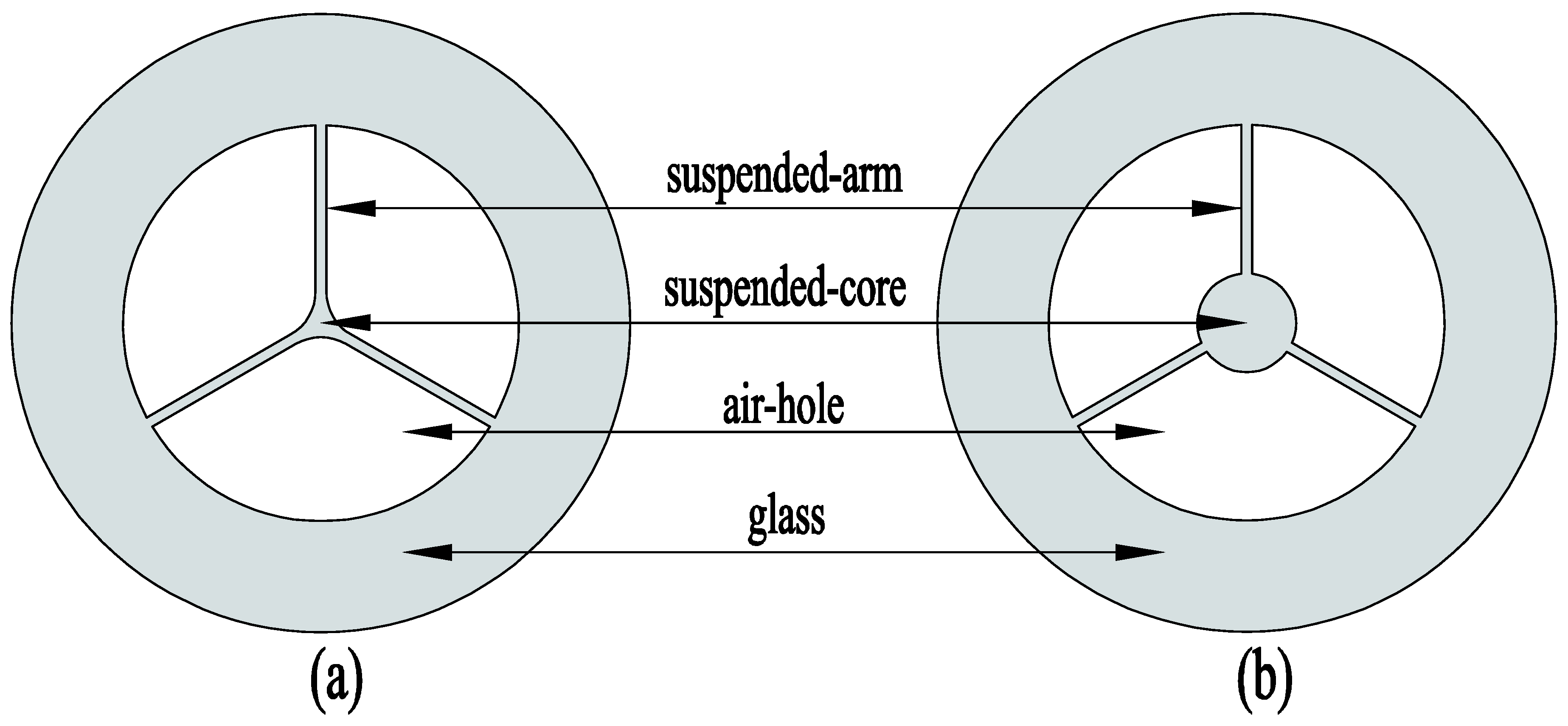
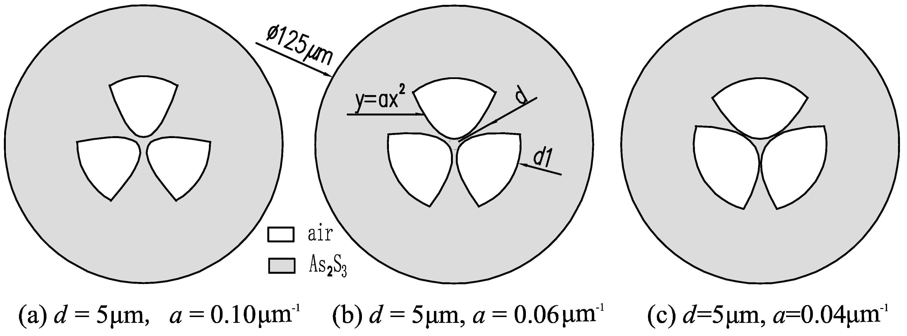
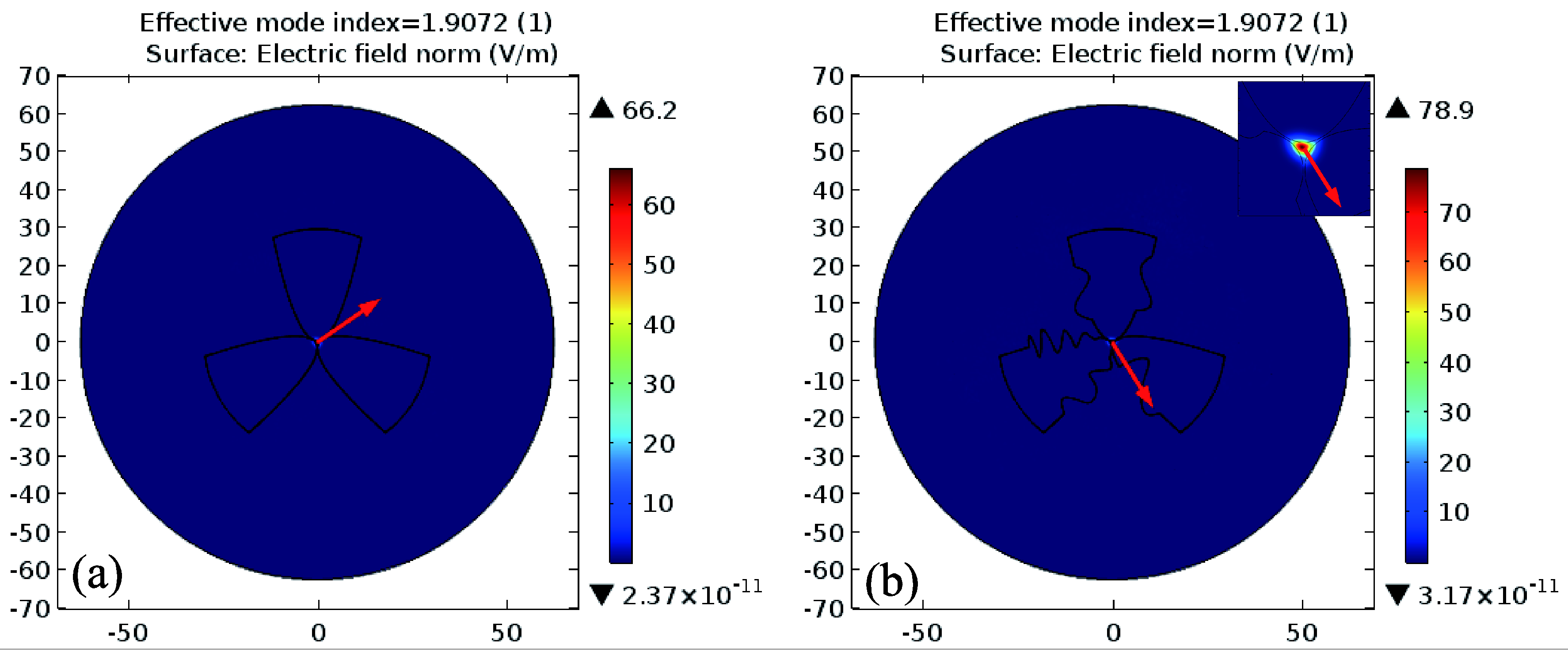
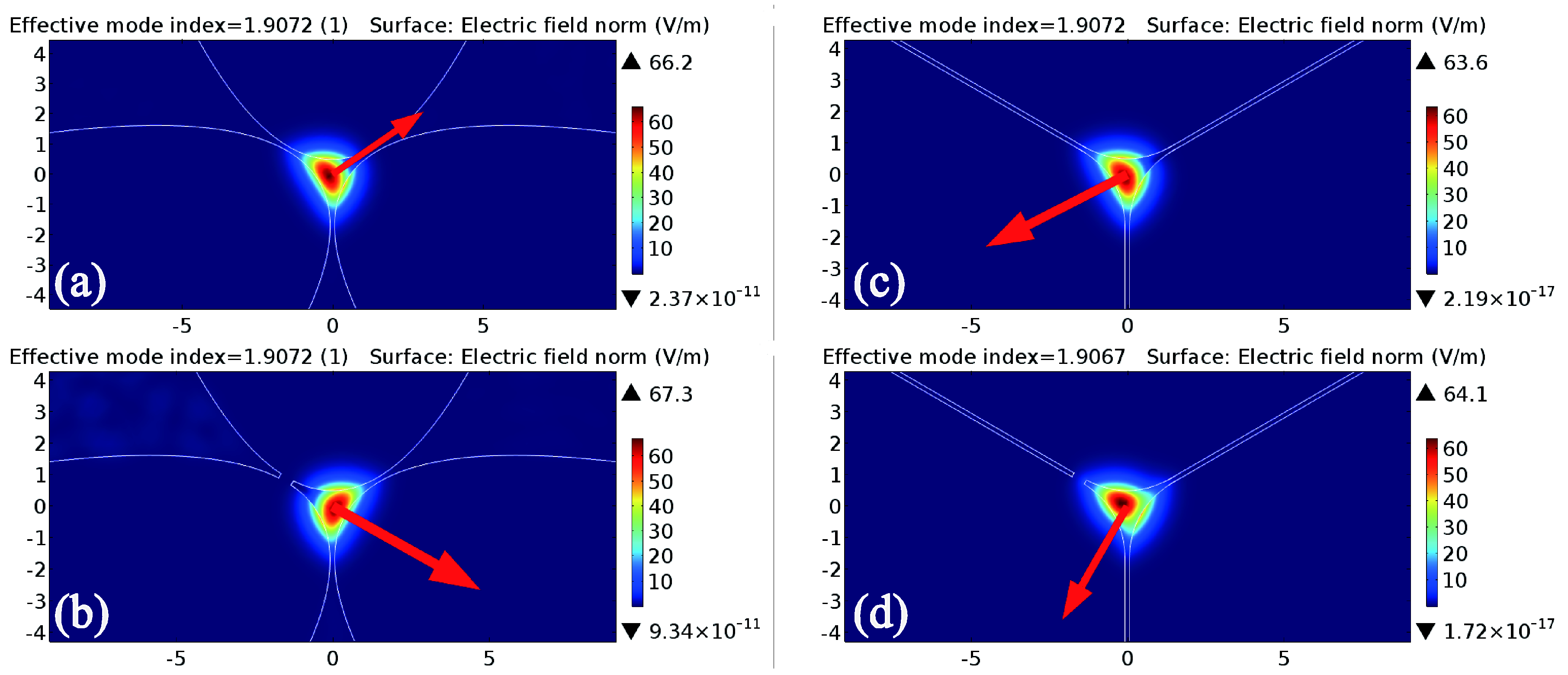
2. Structure Design
3. Characteristics Analysis
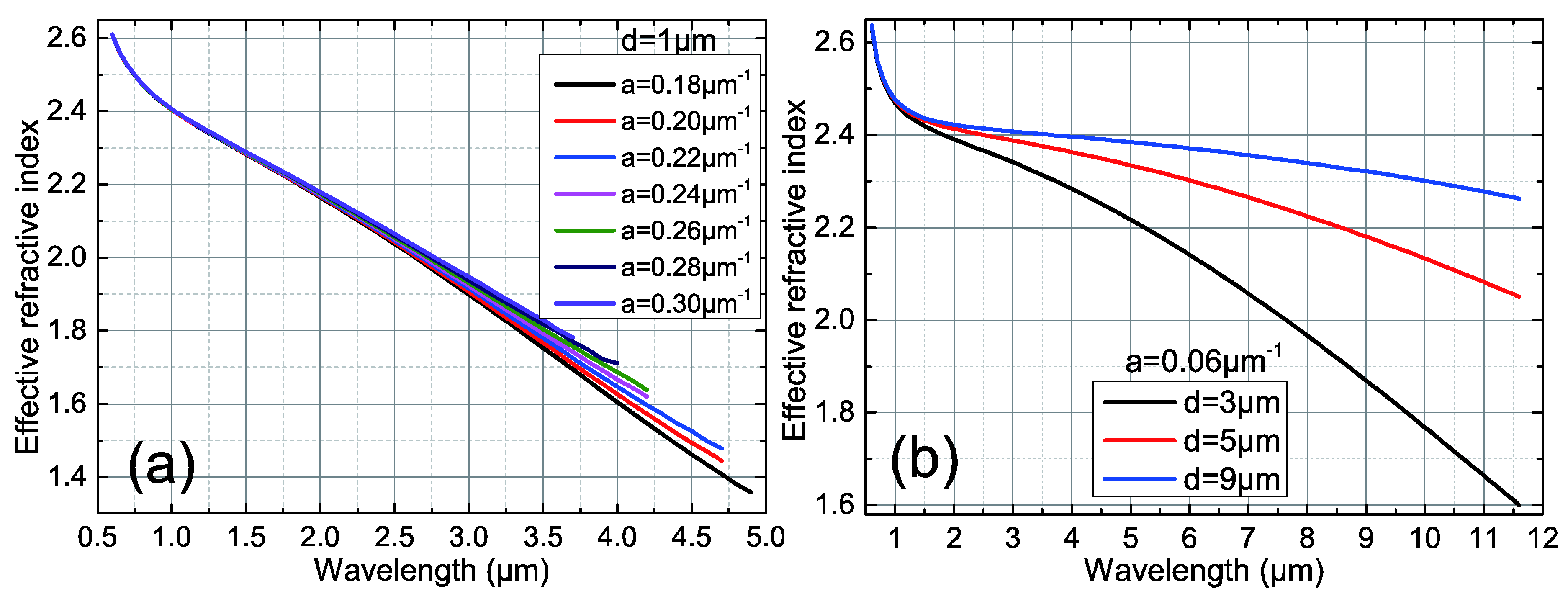
3.1. Effective Refractive Index
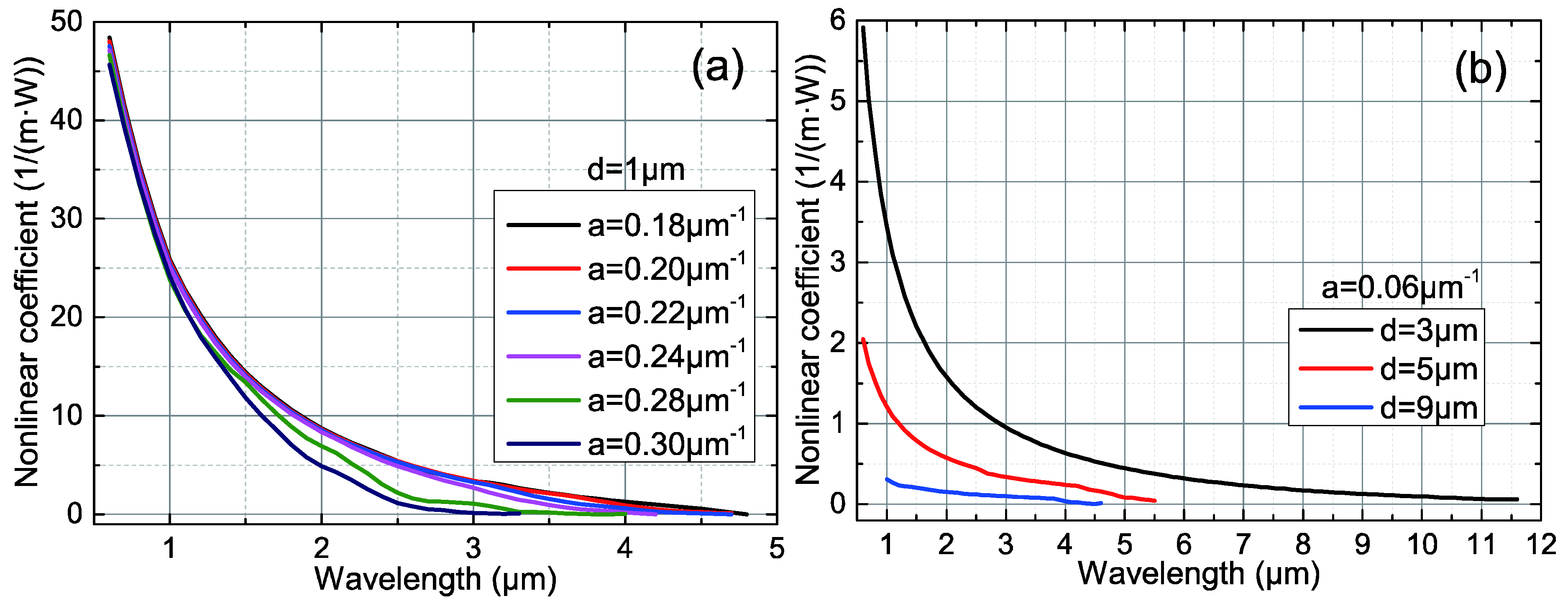
3.2. Nonlinear Coefficient
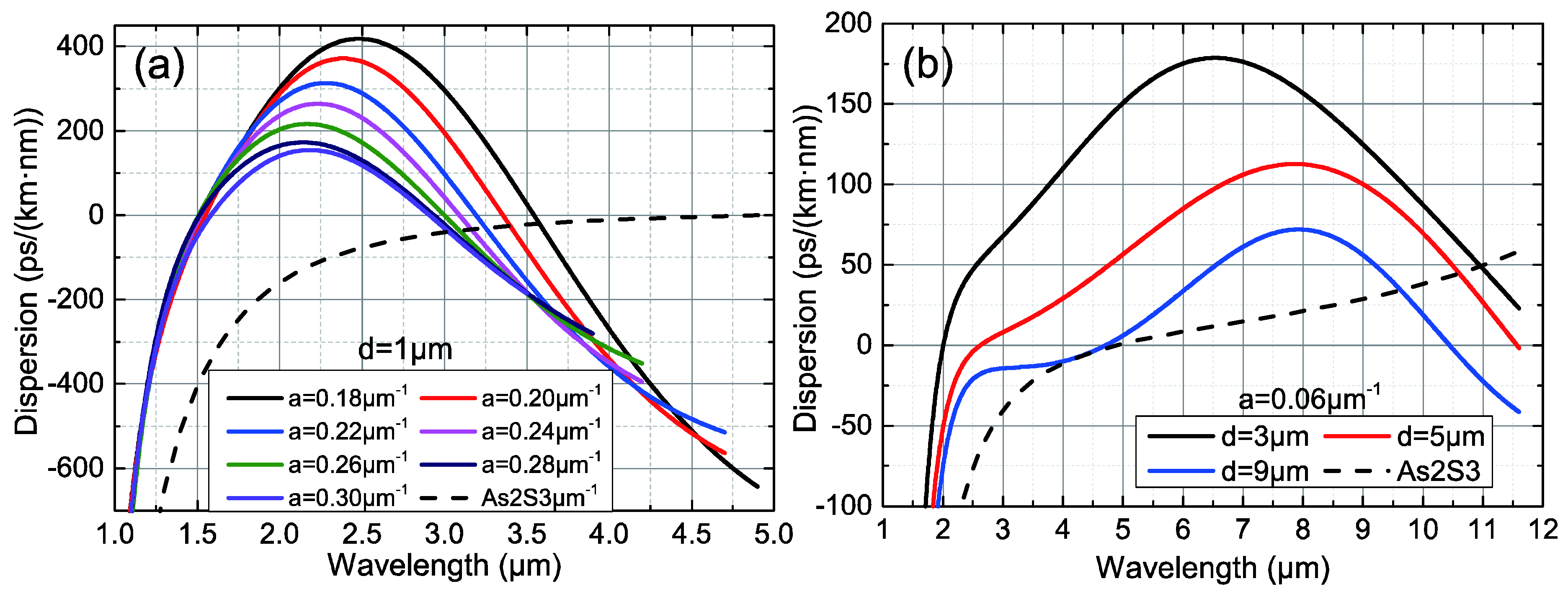
3.3. Chromatic Dispersion
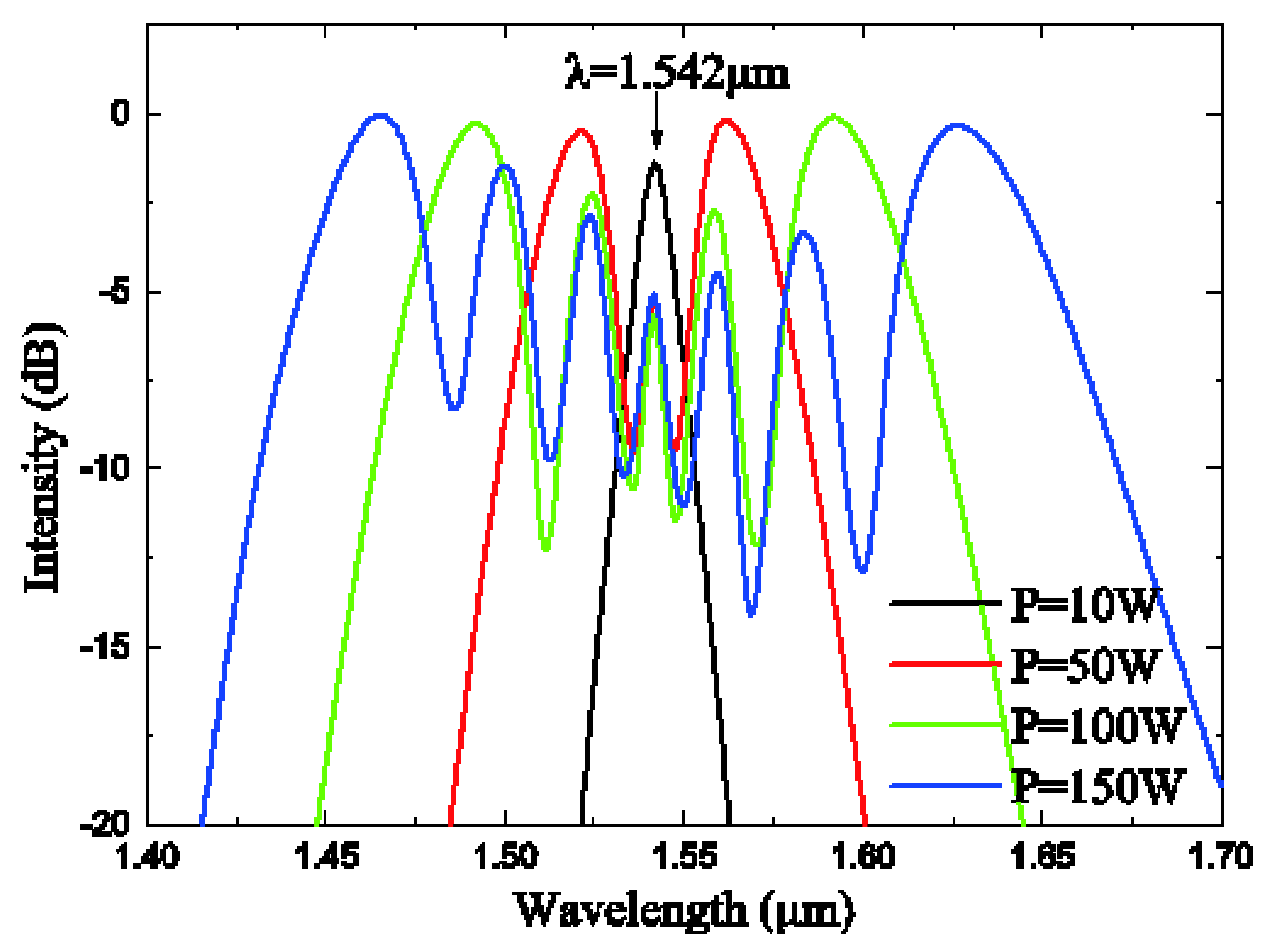
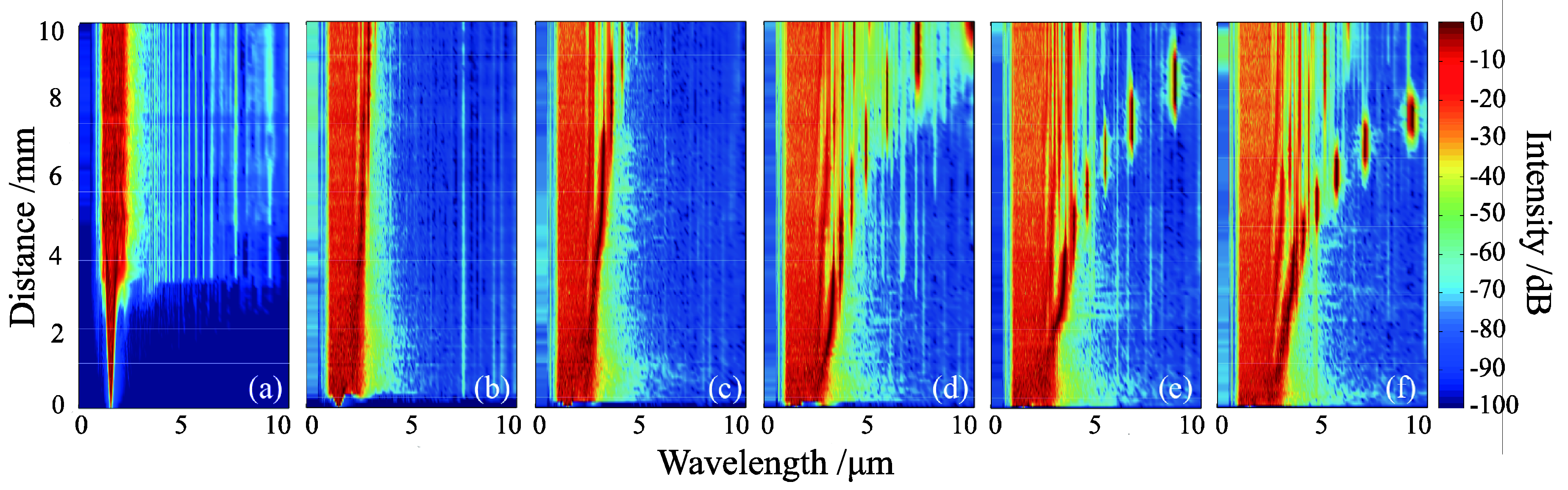
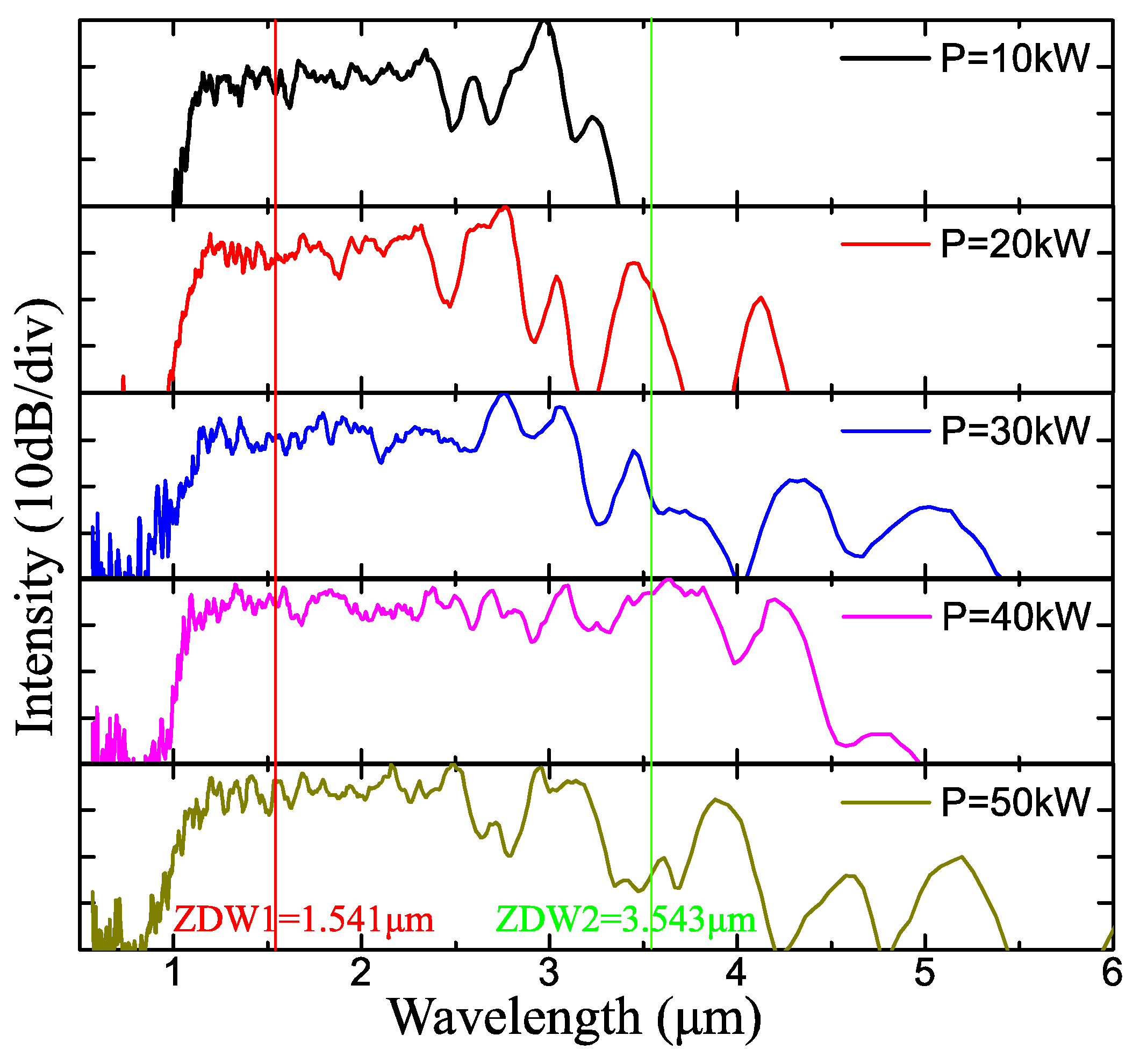
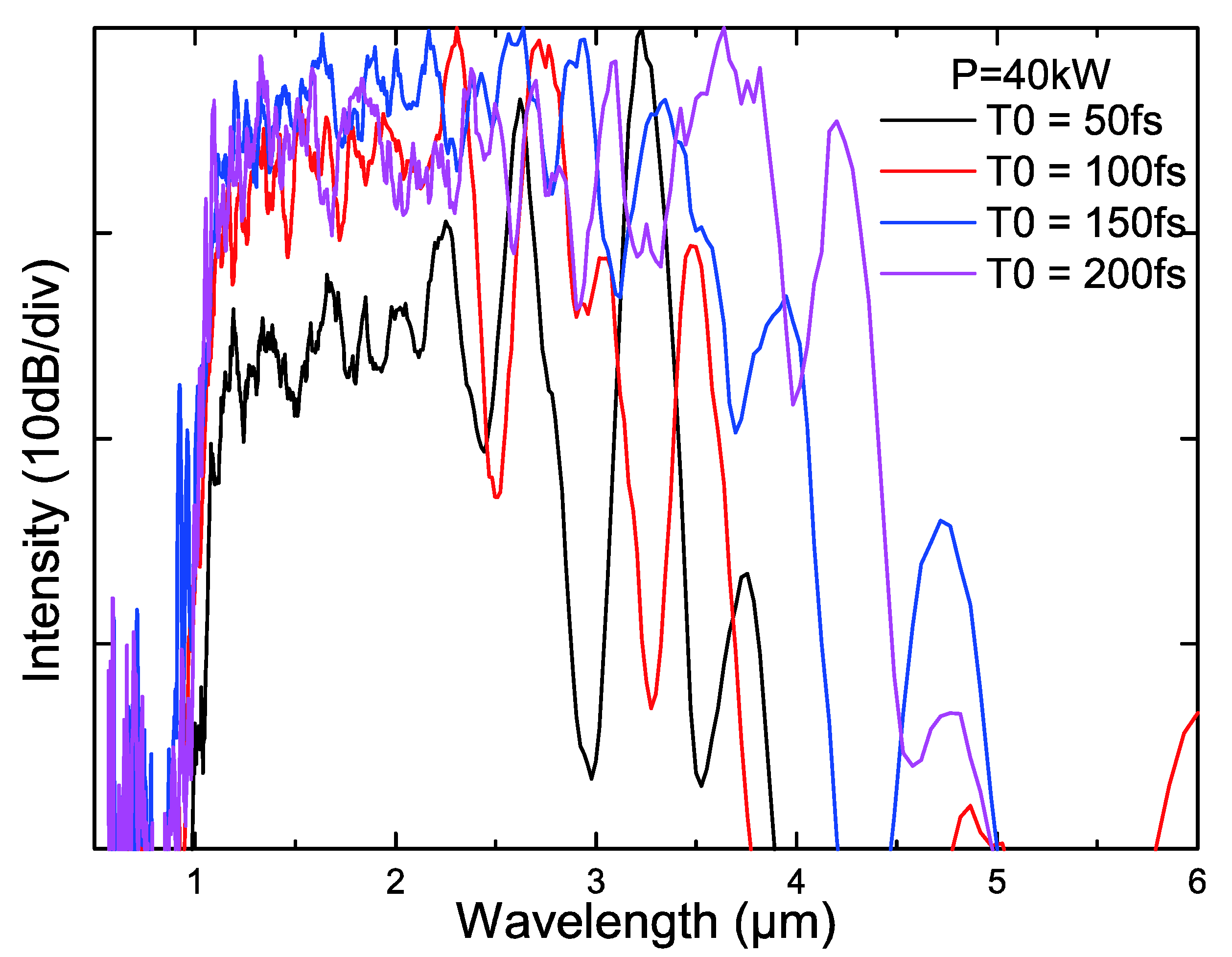
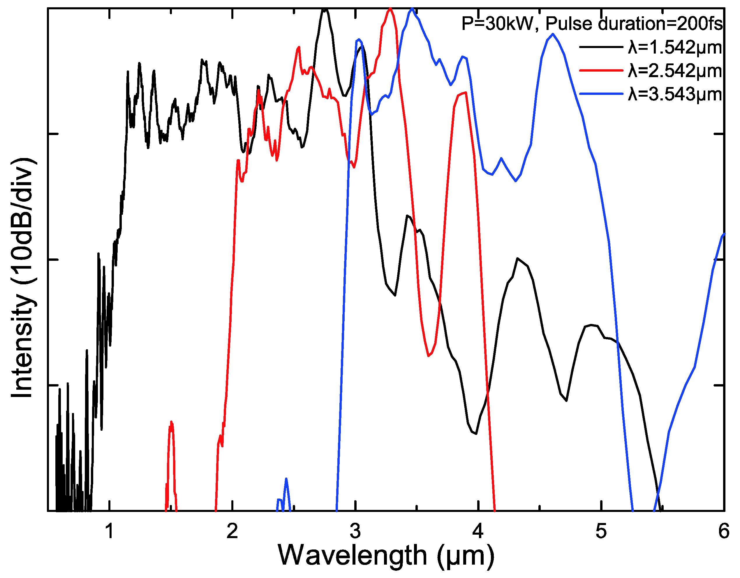
3.4. Supercontinuum
4. Conclusions
Author Contributions
Funding
Acknowledgments
Conflicts of Interest
References
- Poudel, C.; Kaminski, C.F. Supercontinuum radiation in fluorescence microscopy and biomedical imaging applications. J. Opt. Soc. Am. B 2019, 36, A139–A153. [Google Scholar] [CrossRef]
- Kano, H.; Hamaguchi, H.-O. In-vivo multi-nonlinear optical imaging of a living cell using a supercontinuum light source generated from a photonic crystal fiber. Opt. Express 2006, 14, 2798–2804. [Google Scholar] [CrossRef] [PubMed]
- Murugkar, S.; Brideau, C.; Ridsdale, A.; Naji, M.; Stys, P.K.; Anis, H. Coherent anti-Stokes Raman scattering microscopy using photonic crystal fiber with two closely lying zero dispersion wavelengths. Opt. Express 2007, 15, 14028–14037. [Google Scholar] [CrossRef] [PubMed]
- Monro, T.; Ebendorff-Heidepriem, H.; Schartner, E.; Warren-Smith, S. Sensing in suspended-core optical fibers. Proc. IEEE Winter Top. 2011, 159–160. [Google Scholar] [CrossRef]
- Bravo, M.; Fernández-Vallejo, M.; Echapare, M.; López-Amo, M.; Kobelke, J.; Schuster, K. Multiplexing of six micro-displacement suspended-core Sagnac interferometer sensors with a Raman-Erbium fiber laser. Opt. Express 2013, 21, 2971–2977. [Google Scholar] [CrossRef]
- Xuan, K.D.; Van, L.C.; Long, V.C.; Dinh, Q.H.; Xuan, L.V.; Trippenbach, M.; Buczynski, R. Dispersion characteristics of a suspended-core optical fiber infiltrated with water. Appl. Opt. 2017, 56, 1012–1019. [Google Scholar] [CrossRef]
- Russell, P. Photonic crystal fibers. Science 2003, 299, 358–362. [Google Scholar] [CrossRef]
- Knight, J.C. Photonic crystal fibres. Nature 2003, 424, 847–851. [Google Scholar] [CrossRef]
- Dong, L.; Thomas, B.K.; Fu, L. Highly nonlinear silica suspended core fibers. Opt Express 2008, 16, 16423–16430. [Google Scholar] [CrossRef]
- Yakasai, I.; Abas, P.E.; Kaijage, S.F.; Caesarendra, W.; Begum, F. Proposal for a Quad-Elliptical Photonic Crystal Fiber for Terahertz Wave Guidance and Sensing Chemical Warfare Liquids. Photonics 2019, 6, 78. [Google Scholar] [CrossRef]
- Price, J.H.V.; Monro, T.M.; Ebendorff-Heidepriem, H.; Poletti, F.; Horak, P.; Finazzi, V.; Leong, J.Y.Y.; Petropoulos, P.; Flanagan, J.C.; Brambilla, G.; et al. Mid-IR Supercontinuum Generation From Nonsilica Microstructured Optical Fibers. IEEE J. Sel. Top. Quantum Electron. 2007, 13, 738–749. [Google Scholar] [CrossRef]
- Jiao, K.; Yao, J.; Wang, X.-G.; Wang, X.; Zhao, Z.; Zhang, B.; Si, N.; Liu, J.; Shen, X.; Zhang, P.; et al. 1.2–15.2 μm supercontinuum generation in a low-loss chalcohalide fiber pumped at a deep anomalous-dispersion region. Opt. Lett. 2019, 44, 5545–5548. [Google Scholar] [CrossRef]
- Tao, G.; Ebendorff-Heidepriem, H.; Stolyarov, A.M.; Danto, S.; Badding, J.V.; Fink, Y.; Ballato, J.; Abouraddy, A.F. Infrared fibers. Adv. Opt. Photonics 2015, 7, 379. [Google Scholar] [CrossRef]
- El-Amraoui, M.; Gadret, G.; Jules, J.C.; Fatome, J.; Fortier, C.; Désévédavy, F.; Skripatchev, I.; Messaddeq, Y.; Troles, J.; Brilland, L.; et al. Microstructured chalcogenide optical fibers from As2S3 glass: Towards new IR broadband sources. Opt. Express 2010, 18, 26655–26665. [Google Scholar] [CrossRef] [PubMed]
- Mouawad, O.; Picot-Clémente, J.; Amrani, F.; Strutynski, C.; Smektala, F. 3.5-µm bandwidth mid-infrared supercontinuum generation in a 2-cm long suspended-core chalcogenide fiber. In Proceedings of the Specialty Optical Fibers, Barcelona, Spain, 27–31 July 2014; ISBN 978-1-55752-820-9. [Google Scholar] [CrossRef]
- Gao, W.; El Amraoui, M.; Liao, M.; Kawashima, H.; Duan, Z.; Deng, D.; Cheng, T.; Suzuki, T.; Messaddeq, Y.; Ohishi, Y. Mid-infrared supercontinuum generation in a suspended-core As2S3 chalcogenide microstructured optical fiber. Opt. Express 2013, 21, 9573–9583. [Google Scholar] [CrossRef] [PubMed]
- Mouawad, O.; Kedenburg, S.; Steinle, T.; Steinmann, A.; Kibler, B.; Désévédavy, F.; Gadret, G.; Jules, J.-C.; Giessen, H.; Smektala, F. Experimental long-term survey of mid-infrared supercontinuum source based on As2S3 suspended-core fibers. Appl. Phys. B Lasers Opt. 2016, 122, 177. [Google Scholar] [CrossRef]
- Xue, Z.; Liu, S.; Zhao, Z.; Mi, N.; Wu, B.; Li, X.; Zhang, P.; Wang, X. Infrared Suspended-Core Fiber Fabrication Based on Stacked Chalcogenide Glass Extrusion. J. Lightwave Technol. 2018, 36, 2416–2421. [Google Scholar] [CrossRef]
- Gao, W.; Duan, Z.; Asano, K.; Cheng, T.; Deng, D.; Matsumoto, M.; Misumi, T.; Suzuki, T.; Ohishi, Y. Mid-infrared supercontinuum generation in a four-hole As2S5 chalcogenide microstructured optical fiber. Appl. Phys. B 2014, 116, 847–853. [Google Scholar] [CrossRef]
- Ebendorff-Heidepriem, H.; Warren-Smith, S.C.; Monro, T.M. Suspended nanowires: Fabrication, design and characterization of fibers with nanoscale cores. Opt. Express 2009, 17, 2646–2657. [Google Scholar] [CrossRef]
- Wang, L.; Ma, W.; Zhang, P.; Zhu, L.; Yang, D.; Wang, X.; Dai, S. Mid-Infrared Gas Detection Using a Chalcogenide Suspended-Core Fiber. J. Lightwave Technol. 2019, 37, 5193–5198. [Google Scholar] [CrossRef]
- Tian, Y.; Zhang, P.; Li, X.; Nie, Q.; Wang, R.; Sun, L.; Chen, P.; Xue, Z.; Wang, X.; Dai, S.; et al. Fabrication and Characterization of Three-hole As2S3 Suspended-Core Fibers Based on Robust Extrusion. IEEE Access 2018, 6, 41093–41098. [Google Scholar] [CrossRef]
- Gao, W.; Duan, Z.; Asano, K.; Cheng, T.; Deng, D.; Matsumoto, M.; Misumi, T.; Suzuki, T.; Ohishi, Y. Supercontinuum Generation in an As2S5 Chalcogenide Microstructured Optical Fiber. In Proceedings of the 2014 Conference on Lasers and Electro-Optics (CLEO)-Laser Science to Photonic Applications, San Jose, CA, USA, 8–13 June 2014; IEEE: San Jose, CA, USA, 2014; Volume 116. [Google Scholar]
- Cheng, T.; Kanou, Y.; Deng, D.; Xue, X.; Matsumoto, M.; Misumi, T.; Suzuki, T.; Ohishi, Y. Mid-infrared supercontinuum generation in an AsSe2-As2S5 hybrid microstructured optical fiber. In Proceedings of the 2014 5th International Conference on Optical Communication Systems (OPTICS), Vienna, Austria, 28–30 August 2014; pp. 1–6. [Google Scholar]
- Peng, T.; Xu, T.; Wang, X. Simulation Study on Dispersion Properties of As2S3 Three-Bridge Suspended-Core Fiber. IEEE Access 2017, 5, 17240–17245. [Google Scholar] [CrossRef]
- Duhant, M.; Renard, W.; Canat, G.; Nguyen, T.N.; Smektala, F.; Troles, J.; Coulombier, Q.; Toupin, P.; Brilland, L.; Bourdon, P.; et al. Fourth-order cascaded Raman shift in AsSe chalcogenide suspended-core fiber pumped at 2 μm. Opt. Lett. 2011, 36, 2859. [Google Scholar] [CrossRef]
- Anashkina, E.A.; Shiryaev, V.S.; Koptev, M.Y.; Stepanov, B.S.; Muravyev, S.V. Development of As-Se tapered suspended-core fibers for ultra-broadband mid-IR wavelength conversion. J. Non-Cryst. Solids 2018, 480, 43–50. [Google Scholar] [CrossRef]
- Coscelli, E.; Poli, F.; Li, J.; Cucinotta, A.; Selleri, S. Dispersion Engineering of Highly Nonlinear Chalcogenide Suspended-Core Fibers. IEEE Photonics J. 2015, 7, 1–8. [Google Scholar] [CrossRef]
- Rodney, W.; Malitson, I.; King, T. Refractive Index of Arsenic Trisulfide. JOSA 1958, 48, 633–635. [Google Scholar] [CrossRef]
- Knight, J.C.; Birks, T.A.; Russell, P.S.J.; Atkin, D.M. All-silica single-mode optical fiber with photonic crystal cladding: Errata. Opt. Lett. 1996, 21, 1547–1549. [Google Scholar] [CrossRef]
- Harrington, J.A. Infrared Fibers and their Applications; SPIE Press: Bellingham, WS, USA, 2004. [Google Scholar] [CrossRef]
- Chaudhari, C.; Suzuki, T.; Ohishi, Y. Design of Zero Chromatic Dispersion Chalcogenide As S Glass Nanofibers. IEEE/OSA J. Lightwave Technol. J. Lightwave Technol. 2009, 27, 2095–2099. [Google Scholar] [CrossRef]
- Dudley, J.; Genty, G.; Coen, S. Supercontinuum generation in photonic crystal fiber. Rev. Mod. Phys. 2006, 78, 1135. [Google Scholar] [CrossRef]
- Xiong, C.; Magi, E.; Luan, F.; Tuniz, A.; Dekker, S.; Sanghera, J.S.; Shaw, L.B.; Aggarwal, I.D.; Eggleton, B.J. Characterization of picosecond pulse nonlinear propagation in chalcogenide As2S3 fiber. Appl. Opt. 2009, 48, 5467–5474. [Google Scholar] [CrossRef]
- Cimpl, Z.; Kosek, F.; Husa, V.; Svoboda, J. Refractive index of arsenic trisulphide. Czechoslov. J. Phys. B 1981, 31, 1191–1194. [Google Scholar] [CrossRef]
- Yang, T.; Ding, C.; Guo, Y.J. A Highly Birefringent and Nonlinear AsSe2–As2S5 Photonic Crystal Fiber With Two Zero-Dispersion Wavelengths. IEEE Photonics J. 2019, 11, 1–7. [Google Scholar] [CrossRef]
- Petersen, C.R.; Møller, U.; Kubat, I.; Zhou, B.; Dupont, S.; Ramsay, J.; Benson, T.; Sujecki, S.; Abdel-Moneim, N.; Tang, Z.; et al. Mid-infrared supercontinuum covering the 1.4–13.3 μm molecular fingerprint region using ultra-high NA chalcogenide step-index fibre. Nat. Photonics 2014, 8, 830–834. [Google Scholar] [CrossRef]
- Du, T.; Li, Y.; Wang, K.; Cai, Z.; Xu, H.; Xu, B.; Mashinsky, V.M.; Luo, Z. 2.01–2.42 μm All-Fiber Femtosecond Raman Soliton Generation in a Heavily Germanium Doped Fiber. IEEE J. Sel. Top. Quantum Electron. 2019, 25, 1–7. [Google Scholar] [CrossRef]
- Huang, R.; Zhou, R.; Li, Q. Mid-Infrared Supercontinuum Generation in Chalcogenide Photonic Crystal Fibers with a Weak CW Trigger. J. Lightwave Technol. 2020, 38, 1522–1528. [Google Scholar] [CrossRef]
- Jiao, K.; Yao, J.; Zhao, Z.; Wang, X.; Si, N.; Wang, X.; Chen, P.; Xue, Z.; Tian, Y.; Zhang, B.; et al. Mid-infrared flattened supercontinuum generation in all-normal dispersion tellurium chalcogenide fiber. Opt. Express 2019, 27, 2036–2043. [Google Scholar] [CrossRef]
- Yang, L.; Li, Y.; Zhang, B.; Wu, T.; Zhao, Y.; Hou, J. 30-W supercontinuum generation based on ZBLAN fiber in an all-fiber configuration. Photonics Res. 2019, 7, 1061. [Google Scholar] [CrossRef]
- Diouf, M.; Mandeng, L.M.; Tchawoua, C.; Zghal, M. Numerical Investigation of Supercontinuum Generation Through AsSe2/As2S5 Chalcogenide Photonic Crystal Fibres and Rib Structures. J. Lightwave Technol. 2019, 37, 5692–5698. [Google Scholar] [CrossRef]
- Park, K.; Na, J.; Kim, J.; Jeong, Y. Numerical Study on Supercontinuum Generation in an Active Highly Nonlinear Photonic Crystal Fiber With Anomalous Dispersion. IEEE J. Quantum Electron. 2020, 56, 1–9. [Google Scholar] [CrossRef]


| Year/Ref. | Glass Components | Structure | Length | ZDW | Pump Wavelength | Pump Peak Power | FWHM | Spectral Bandwidth |
|---|---|---|---|---|---|---|---|---|
| Unit | cm | μm | μm | kW | fs | μm | ||
| 2013/[16] | As2S3 | 3-hole | 1.3/2.4 | 2.52 | 2.6 | 0.24–1.32 | ~200 | 1.520–4.610 |
| 2014/[15] | As2S3 | 3-hole | 2 | 2.5 | 2.5 | 1.25–4.86 | 200 | 0.6–4.1 |
| 2014/[23] | As2S5 | 4-hole | 4.8 | 2.28 | 2.3 | 0.22–1.55 | 200 | 1.370–5.650 |
| 2014/[24] | AsSe2-As2S5 | 4-hole | 2 | 3.38 | 3.389 | 1.356 | ~200 | 1.256–5.400 |
| 2016/[17] | As2S3 | 3-hole | 2.5 | 2.65 | 3.5 | 0.015 | 300 | 2.5–5.5 |
| 2018/[24] | As2S3-Ge20As20Se15Te45 | 4-hole | 19 | 3.93 | 4.5 | 66 | 150 | 2.06–6.95 |
| d = 1 μm | d = 3 μm | d = 5 μm | d = 9 μm | |
|---|---|---|---|---|
| Mean (μm) | 1.5336 | 2.0814 | 2.6860 | 4.5493 |
| Standard Deviation | 0.0243 | 0.0579 | 0.0687 | 0.1218 |
| β1 (fs/mm) | β2 (fs2/mm) | β3 (fs3/mm) | β4 (fs4/mm) | β5 (fs5/mm) | β6 (fs6/mm) | β7 (fs7/mm) | β8 (fs8/mm) | β9 (fs9/mm) | β10 (fs10/mm) |
|---|---|---|---|---|---|---|---|---|---|
| 5.3381× 10⁵ | −6.73833× 10⁻¹⁶ | 1.31008× 10⁻²⁷ | −4.6199× 10−42 | 2.39585× 10−56 | −4.6505× 10−71 | −2.43177× 10−85 | 5.22843× 10−99 | 5.21097× 10−112 | −7.83179× 10−124 |
© 2020 by the authors. Licensee MDPI, Basel, Switzerland. This article is an open access article distributed under the terms and conditions of the Creative Commons Attribution (CC BY) license (http://creativecommons.org/licenses/by/4.0/).
Share and Cite
Peng, T.; Wang, X.; Xu, T. Arsenic Sulfide Suspended-core Fiber Simulation with Three Parabolic Air Holes for Supercontinuum Generation. Photonics 2020, 7, 46. https://doi.org/10.3390/photonics7030046
Peng T, Wang X, Xu T. Arsenic Sulfide Suspended-core Fiber Simulation with Three Parabolic Air Holes for Supercontinuum Generation. Photonics. 2020; 7(3):46. https://doi.org/10.3390/photonics7030046
Chicago/Turabian StylePeng, Tao, Xunsi Wang, and Tiefeng Xu. 2020. "Arsenic Sulfide Suspended-core Fiber Simulation with Three Parabolic Air Holes for Supercontinuum Generation" Photonics 7, no. 3: 46. https://doi.org/10.3390/photonics7030046
APA StylePeng, T., Wang, X., & Xu, T. (2020). Arsenic Sulfide Suspended-core Fiber Simulation with Three Parabolic Air Holes for Supercontinuum Generation. Photonics, 7(3), 46. https://doi.org/10.3390/photonics7030046