Article

Investigation of the Effect of Intra-Cavity Propagation Delay in Secure Optical Communication Using Chaotic Semiconductor Lasers

1
School of Physics, Southwest University, Chongqing 400715, China
2
Department of Physics, Pondicherry University, Pondicherry 605014, India
3
School of Science, Inner Mongolia University of Science and Technology, Baotou 014010, China
*
Authors to whom correspondence should be addressed.
Photonics 2019, 6(2), 49; https://doi.org/10.3390/photonics6020049
Submission received: 19 March 2019 / Revised: 25 April 2019 / Accepted: 8 May 2019 / Published: 9 May 2019
(This article belongs to the Special Issue Semiconductor Laser Dynamics: Fundamentals and Applications)

Abstract

:
The influence of intra-cavity propagation delay in message encoding and decoding using chaotic semiconductor lasers is numerically investigated. A message is encoded at the transmitter laser by a chaos shift keying scheme and is decoded at the receiver by comparing its output with the transmitter laser. The requisite intra-cavity propagation delay in achieving synchronization of optical chaos is estimated by cross-correlation analysis between the transmitter and receiver lasers’ output. The effect of intra-cavity propagation delay on the message recovery has been analyzed from the bit error rate performance. It is found that despite the intra-cavity propagation delay magnitude being less, it has an impact on the quality of message recovery. We also examine the dependency of injection rate, frequency detuning, modulation depth and bit rate on intra-cavity propagation delay and associated message recovery quality. We found that the communication performance has been adequately improved after incorporating intra-cavity propagation delay correction in the synchronization system.

1. Introduction

The development of high-speed, secure optical communication has been an important field of research in recent times and has been gaining momentum due to both the requirement scenario and the relevant technological advances [1,2,3,4,5,6,7,8,9,10,11]. The possibility of realizing secure optical communication using chaotic laser systems has attracted much attention after the realization of chaos synchronization in nonlinear systems [12]. Semiconductor diode lasers are best suited devices to produce broadband chaotic output and, thus, enable optical encoding and decoding processes [13,14,15,16,17,18,19,20,21,22,23,24,25,26,27,28,29,30,31,32]. A typical secure optical communication scheme involves two semiconductor lasers acting as transmitter laser (TL) and receiver laser (RL), in which the transmitter’s output intensity is rendered chaotic through optical feedback. Messages masked in the chaotic output of the transmitter can be decoded at the receiver, by achieving synchronization between TL and RL optical outputs. In solid-state lasers, the encoding and decoding binary bit-sequences had been demonstrated by Colet and Roy [33]. A square wave message embedded with erbium-doped fiber ring laser, where the chaotic signal generated by optical feedback, was experimentally demonstrated in 1998 [1]. Message encoding and decoding using a system of chaotic external-cavity semiconductor lasers have been demonstrated [34]. Chaos communications using semiconductor lasers with optical feedback, optical injection locking, and optoelectronic feedback were reported, and compared [19,35].
Chaos modulation (CMO) [1,36,37,38], chaos masking (CMA) [39,40,41], and chaos shift keying (CSK) [42,43,44,45] synchronization schemes have been proposed for encoding and decoding of messages in laser systems. In the CSK scheme, two separated states corresponding to bit sequences (“1” and “0”) of a message are sent to a receiver laser and based on the synchronization between TL and RL, the message is decoded at the receiver [42]. A real data, video signal transmission in chaos communication using the system of semiconductor lasers was demonstrated by Annovazzi-Lodi et al. [46]. In 2005, a field-based experiment of chaos-based optical communication by CSK scheme of encoding using semiconductor lasers with the optical fiber networks has been demonstrated [4]. In spite of all existing work, to implement secure optical communication in practical use needs extensive studies, for example, improvement in synchronization while allowing parameter mismatch between transmitter and receiver laser, robustness in communications and enhancement of the degree of security [47]. A good message recovery is possible if the synchronization between transmitter and receiver laser is best. In a recent study the synchronization quality is shown to be affected by intra-cavity propagation delay ( τ P D ) in chaotic semiconductor lasers [48,49].
In this article, we discuss our numerical investigations on the effect of intra-cavity propagation delay on the message encoding and decoding using uni-directionally coupled semiconductor lasers. Based on the CSK scheme, we encode 1.2 Gbit/s bit rate (BR) message with the chaotic output of the transmitter laser and transmit to receiver laser. The message is decoded at the receiver laser and studied the effect of intra-cavity propagation delay τ P D on message recovery. The message recovery quality has been evaluated and characterized by bit error rate (BER) analysis of the recovered message. We have systematically investigated the influence of intra-cavity propagation delay in the message recovery process, by considering various coupling rates, detunings, modulation depths, and bit rates of the encoded message. The BER of the recovered message has been reduced after considering intra-cavity propagation delay correction in the receiver laser system.

2. Theory and System Model

The system under investigation consists of an external cavity semiconductor laser serving as the transmitter laser (TL), and another solitary semiconductor laser playing a role of receiver laser (RL). The TL is rendered chaotic by the external cavity optical feedback, and the chaotic output of TL is uni-directionally injected to RL. For our numerical analysis both TL and RL are modeled by suitably adapting the Lang–Kobayashi (L–K) rate Equations [13]. L–K model comprises of the laser rate Equations for slowly varying complex electric field E ( t ) and carrier density N ( t ) for both the lasers. The rate Equations for TL and RL are;
E ˙ T ( t ) = 1 + i α 2 G T ( t ) 1 τ p E T ( t ) + κ E T ( t τ e x t ) e i ω T τ e x t + 2 β T N T ( t ) ξ T ( t )
N ˙ T ( t ) = J T e N T ( t ) τ n G T ( t ) | E T ( t ) | 2
E ˙ R ( t ) = 1 + i α 2 G R ( t ) 1 τ p E R ( t ) + η E T ( t τ f ) e i ( ω T τ f + Δ ω t ) + 2 β R N R ( t ) ξ R ( t )
N ˙ R ( t ) = J R e N R ( t ) τ n G R ( t ) | E R ( t ) | 2
In these equations, the indices T and R refer to the transmitter and receiver lasers respectively. J is the lasers’ injection current, e = 1 . 602 × 10 19 C is the electron charge. G ( t ) = g 0 ( N ( t ) N t h ) / ( 1 + ϵ | E ( t ) | 2 ) is the optical gain, where carrier number at threshold N t h = 1 . 5 × 10 8 , linear gain coefficient g 0 = 12 × 10 3 , gain saturation coefficient ϵ = 5 × 10 7 , linewidth enhancement factor α = 3 . 8 , carrier life time τ n = 2 ns, photon life time τ p = 2 ps. The lasers are operated at the wavelength λ = 830 nm. The frequency detuning between the laser is Δ ω = ω T ω R = 2 π Δ f , and the external-cavity round trip time is τ e x t = 10 ns. The Gaussian noise sources ξ is with zero mean and unity variance [14]. Spontaneous emission rate β = 10 6 ns 1 . κ is the transmitter laser’s feedback rate and η is the injection rate between TL and RL. Throughout our investigations, the time of flight ( τ f = 0 ) between TL and RL is kept zero. The time step is 0.2 ps in our simulations.
The message signal is modulated (encoding message) with bias current of transmitter laser by CSK method [42]. In the first term of Equation (2), for encoding purpose the bias current of TL J T can be modified to J T = J m ( 1 + b M ( t ) ) , here b is modulation depth, M ( t ) is pseudo random sequence, i.e., M ( t ) = 1 / 2 ( 1 / 2 ) for a “1” (“0”) bit and J m is bias current of transmitter laser.
The synchronization quality and the associated time delay between the transmitter and receiver laser are estimated by performing cross-correlation (CC) analysis between the outputs of transmitter and receiver laser. The CC in terms of time-shift ( Δ t ) is given by
C ( Δ t ) = [ I T ( t Δ t ) I T ] [ I R ( t ) I R ] [ I T ( t Δ t ) I T ] 2 [ I R ( t ) I R ] 2
where the expectation denoted by . . . is calculated via time average and I T , R = | E T , R | 2 is the total intensity output of the laser. In C C analysis plot, the prominent peak value evaluates the synchronization quality, and location of the peak corresponds to the time delay between TL and RL output. For the ideal case, C would be 1, which relates to perfect synchronization condition.

3. Chaos Synchronization

In this section, we establish the chaos synchronization between the transmitter and receiver laser and present the influence of intra-cavity propagation delay τ P D in the chaos synchronization. The transmitter and receiver laser rate equations, Equations (1)–(4), are numerically solved using the Runge-Kutta algorithm. We consider the chaos shift keying (CSK) scheme for encoding of message signal [37]. The transmitter laser’s pump magnitude is modulated with a message and transmitted to the receiver laser. A digital message signal with 1.2 Gbit/s bit rate is encoded at the transmitter laser with modulation depth b = 0 . 2 . In the simulation, we keep the parameter values as, κ = 9 ns 1 , τ e x t = 10 ns, J m = 1 . 10 I t h , J R = 1 . 08 I t h , η = 15 ns 1 , Δ f = 0 , and τ f = 0 . Although a higher bias currents of laser provides less distortion in the output intensities by the relaxation oscillation as well as provide higher modulation bandwidth, the influence of intra-cavity propagation delay τ P D is found to be more significant in the chaos synchronization of semiconductor lasers when the lasers are operated at low bias currents. Hence, we kept low bias currents for the TL and RL in our investigations.
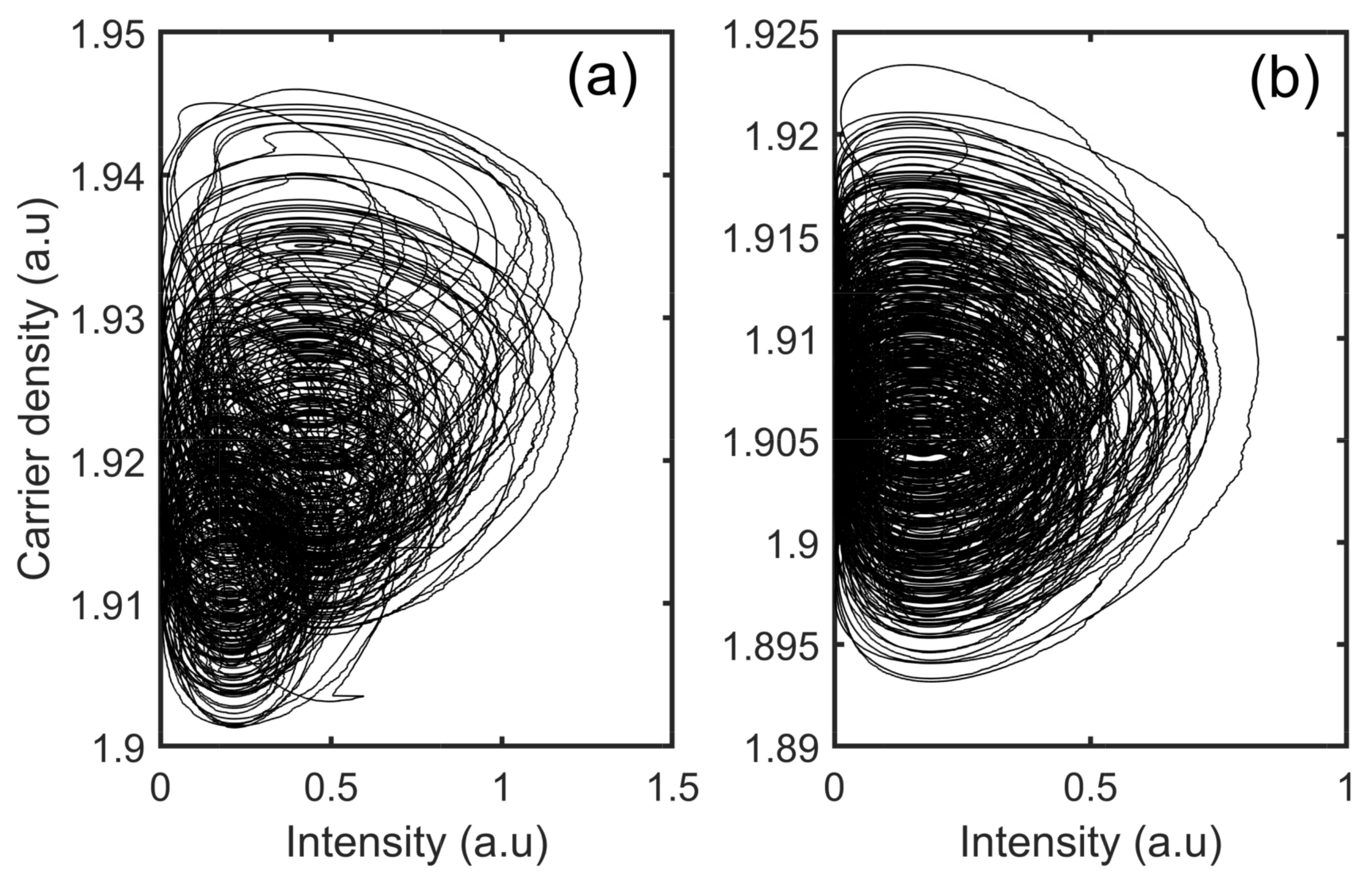
The time evolution output of the transmitter (black trace) and receiver laser (red trace) are obtained and shown in Figure 1. Here, the TL’s time evolution output (black trace) contains both chaotic component arising due to the optical feedback and the message components due to the modulation of bias current. The difference between the laser’s intensity is shown by the grey trace. The red trace (receiver laser) and grey trace (TL-RL) in Figure 1 are shifted vertically for clarity. Figure 2a shows the chaotic attractor of the transmitter laser in the phase space of the intensity and the carrier density. And, Figure 2b corresponds to the chaotic attractor of the receiver laser. The attractors in the transmitter and receiver lasers show the moderately different orbit since generalized synchronization and also due to the encoded message signal at the transmitter laser.
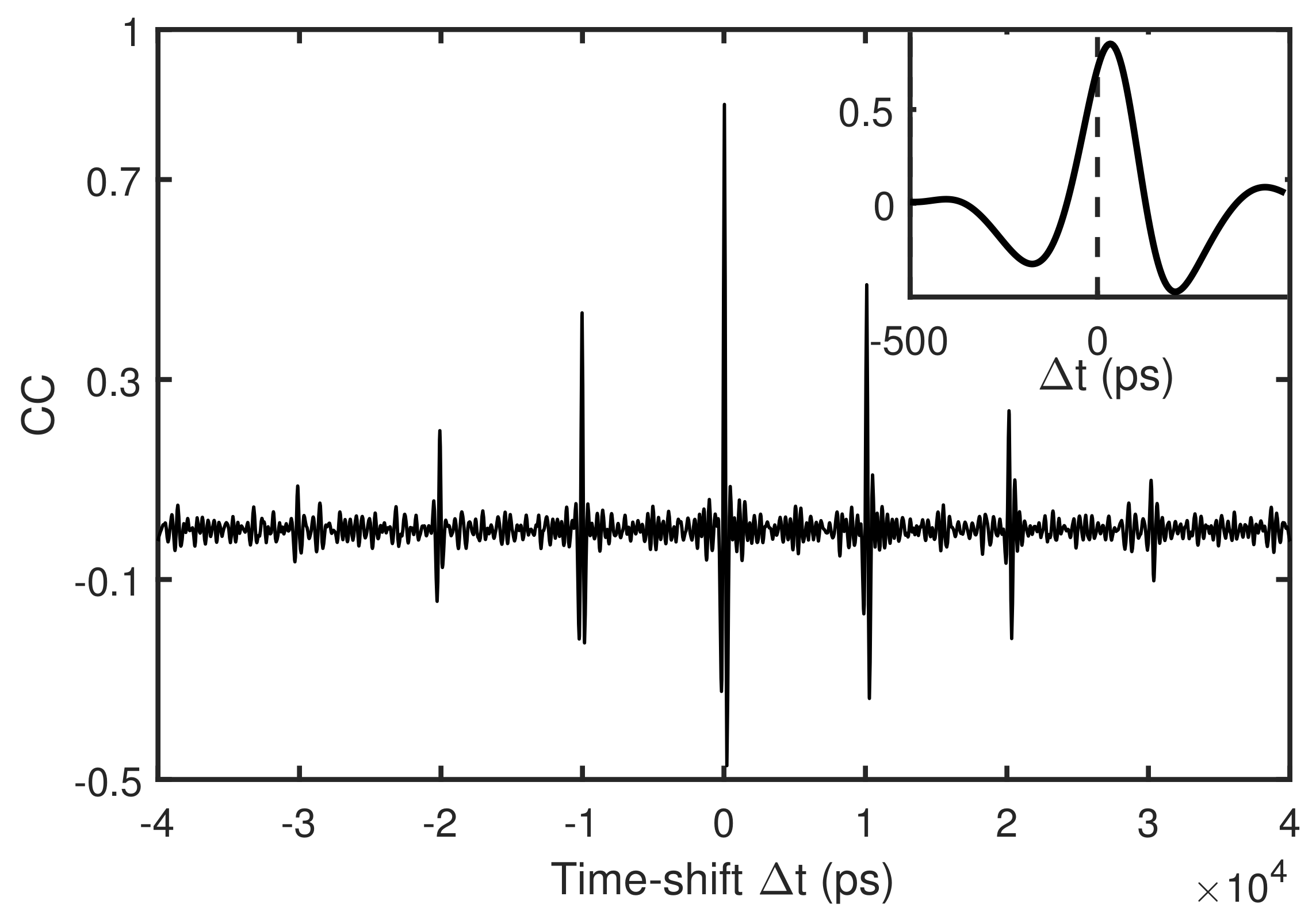
The synchronization quality and the time delay between the coupled lasers are estimated by performing cross-correlation (CC) analysis between TL and RL. From the CC analysis, the prominent peak value ( C m ) evaluates the synchronization quality, and location of the peak in time corresponds to the time delay between TL and RL output. A large value of C m indicates that good synchronization has been achieved. The obtained normalized correlation coefficients is illustrated in Figure 3. The inset figure shows the expanded cross-correlation plot near zero and it can be seen clearly that, although the time of flight ( τ f ) between transmitter and receiver laser is set to zero, the prominent correlation peak is not occurring exactly at zero. This peak shift in time, named as intra-cavity propagation delay ( τ P D ), is eventually due to the propagation of transmitter laser’s output within the receiver’s cavity [48], and it is found to be 32.8 ps in this case. The corresponding maximum correlation ( C m ) value is found to be 0.85. Essentially, this intra-cavity propagation delay time correction should be incorporated in order to obtain a better synchronization between transmitter and receiver laser. Experimental observation of this additional-time delay has been recently demonstrated in chaos synchronization of coupled semiconductor lasers. It is shown that such additional time delay is not arbitrary in character but has a definite functional dependence on a parameter such as injection rate [50]. Despite the intra-cavity propagation delay magnitude is in the order of pico-seconds, cannot be discounted as marginal addition of knowledge and hence in this work we have systematically carried out its effect on secure optical communication using diode lasers.
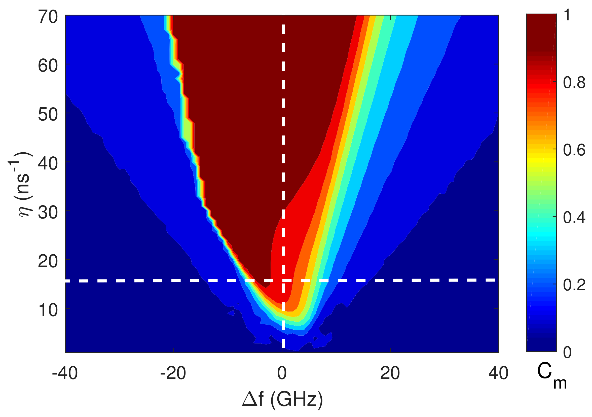
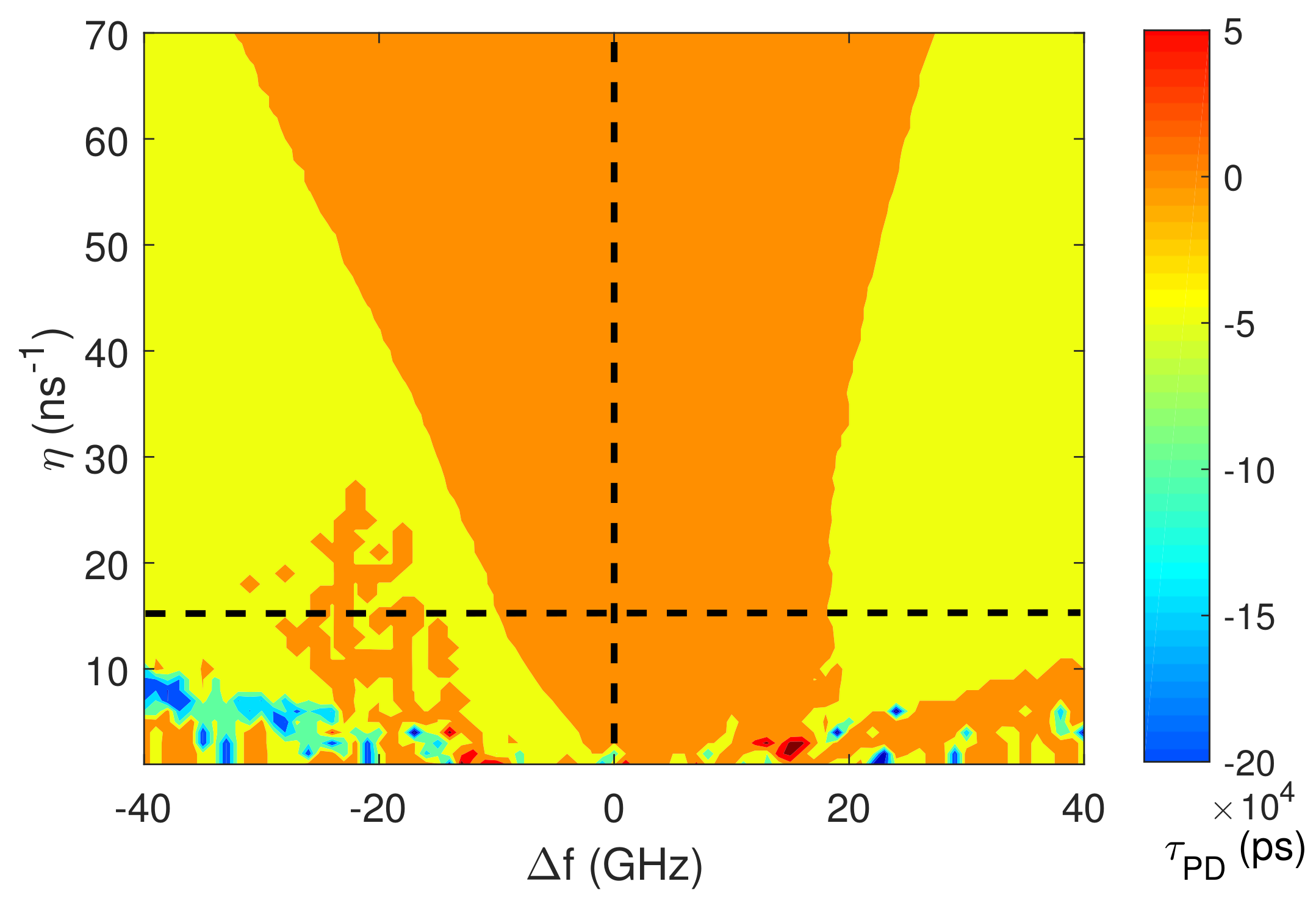
To further characterize the intra-cavity propagation delay and synchronization properties, we have analyzed the robustness of synchronization and the associated τ P D against variations of the coupling parameters. The maximum correlation coefficient C m and τ P D are computed in the plane of the injection parameters (frequency detuning ( Δ f ) versus injection rate ( η )). Thus we obtained two maps for maximal correlation C m variation and intra-cavity propagation delay τ P D which are displayed in Figure 4 and Figure 5, respectively. In Figure 4, we observe that a stronger injection is needed to obtain synchronization for larger detuning and shows asymmetry with respect to the zero detuning. The maximal correlation of C m 0 . 93 (dark red) is expected for higher injection. For lower injection with larger detuning, lower degrees of correlation (blue region) is observed. The shape of the synchronization region is similar to the one reported for different schemes using edge emitting semiconductor lasers [15].
The correlation time-shift (intra-cavity propagation delay τ P D ) required to obtain the maximum correlation value C m in the plane of injection parameters is shown in Figure 5. For a lower injection near zero detuning, high positive magnitude of τ P D is observed (orange color region). The τ P D takes the negative value (yellow region) for positive detuning above +20 GHz with variations of injection rates. Whereas in the negative detuning region, τ P D is observed positive as well as negative with higher magnitudes as negative detuning increased and found to decrease for higher injection rates. In Figure 5, at low injection rates and moderately away from the zero detuning region, the intra-cavity propagation delay value found high in magnitude (in the order of 10 4 ps) since the quality of synchronization is worse in those regions. The asymmetry in the results with respect to the detuning is due to the influence of asymmetry of synchronization performance C m (Figure 4), which is determined by the nonzero linewidth enhancement factor and external injection [51,52].
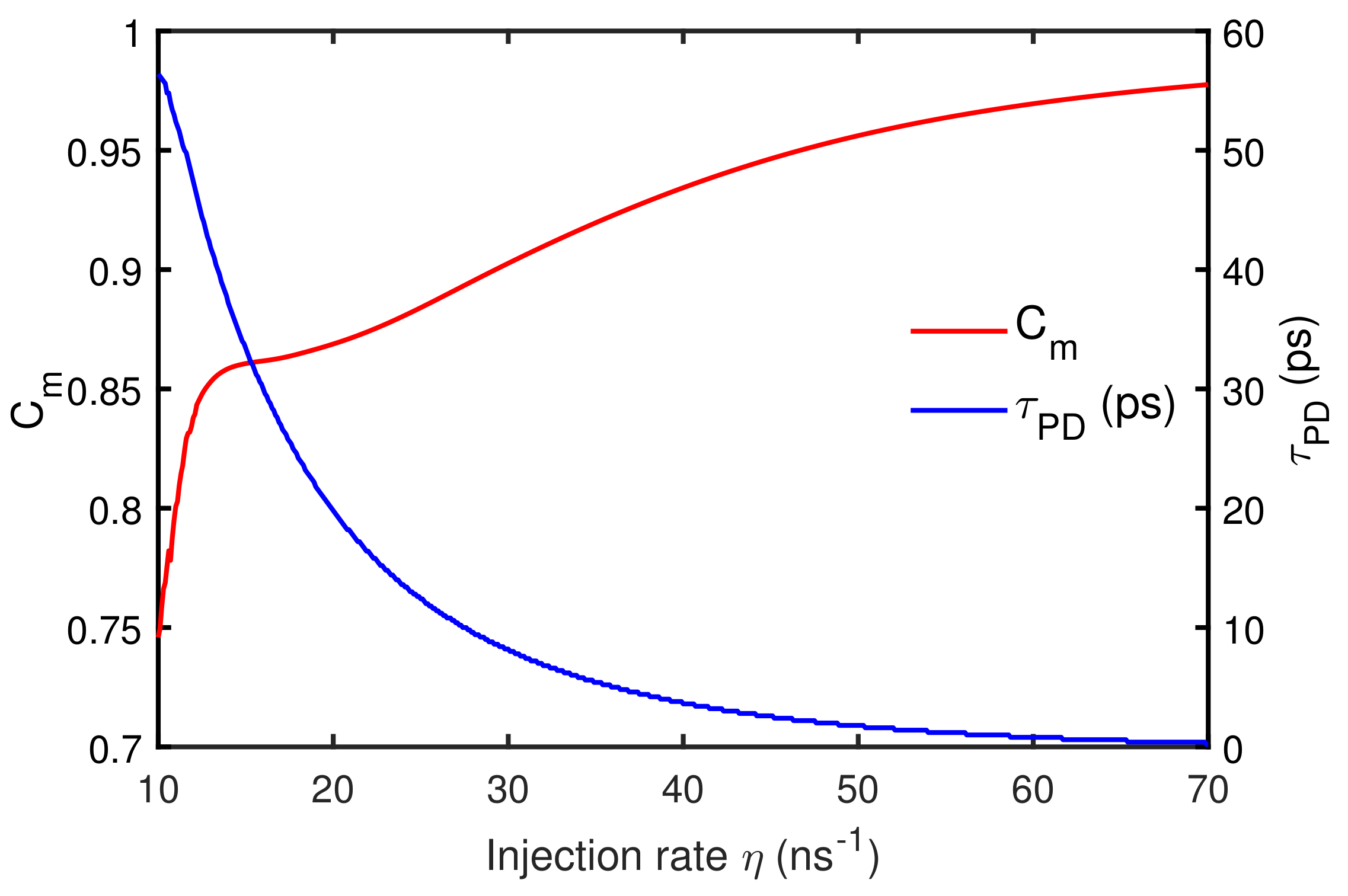
In Figure 6, we show the trend of maximum correlation coefficient C m (Figure 4) and the associated τ P D (Figure 5) for keeping Δ f = 0 with η variation, which is indicated vertical dashed line in Figure 4 and Figure 5. The C m and τ P D for a range of injection rates are shown in Figure 6. The magnitude of τ P D (blue trace) decreases from 56.4 ps to 0.4 ps with increasing injection rate, and the respective C m value (red trace) found to increase from 0.75 to 0.98. The decreasing nature of τ P D for higher injection indicates that the injected signal dominates the dynamics and has greatly controlled the receiver laser’s independent emission [53].
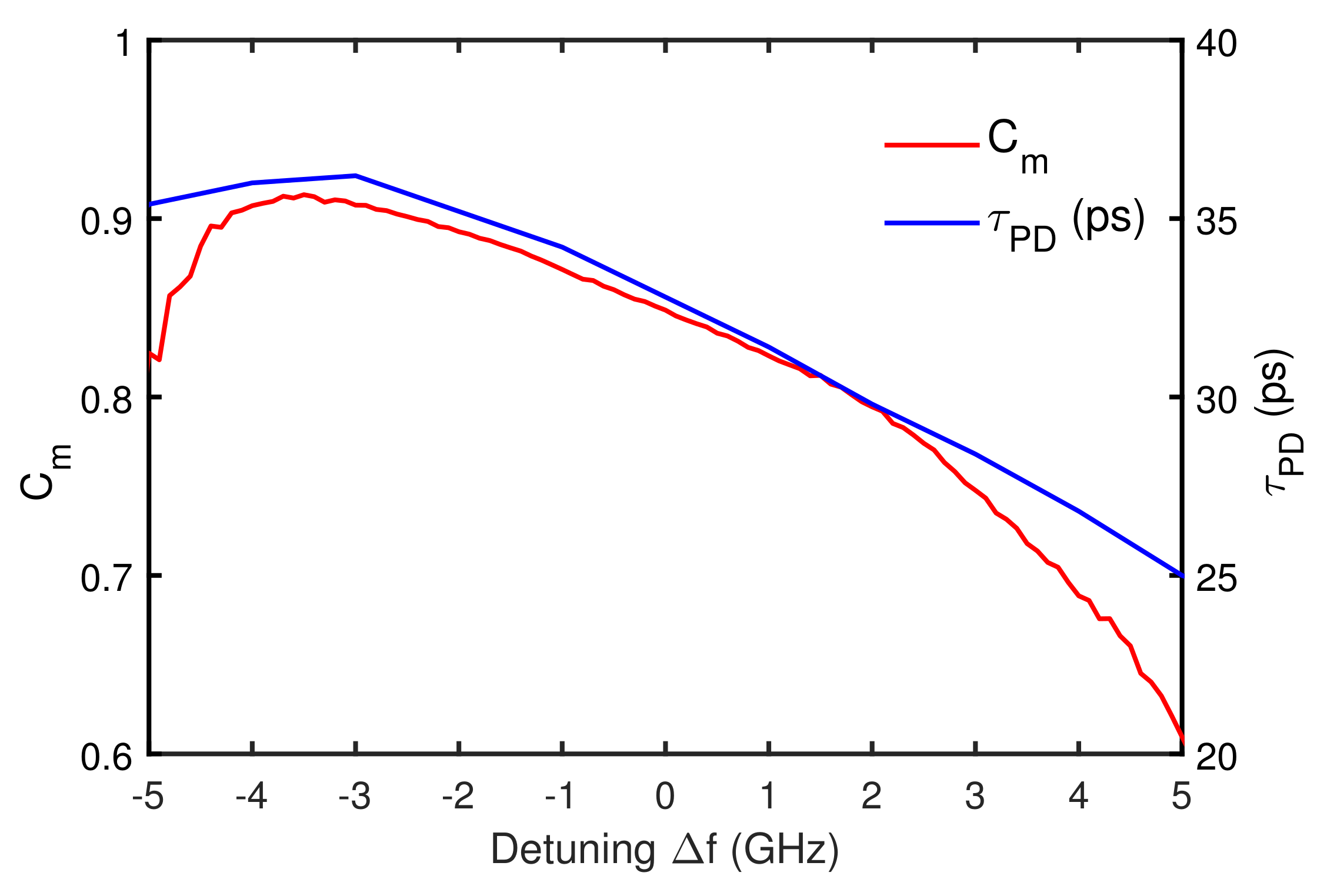
The horizontal dashed lines in Figure 4 and Figure 5 indicate the frequency detuning Δ f variation at η = 15 ns 1 . The dependence of C m and the corresponding τ P D on the frequency detuning variation for keeping η = 15 ns 1 are shown in Figure 7. The simulated results demonstrate that the RL is driven into the chaotic state only for frequency detuning within −5 GHz to +5 GHz. It can be seen that the degree of synchronization C m (red trace) gradually increases and then decreased when the Δ f varied from negative to positive. The associated τ P D (blue trace) found lesser near zero detuning and found increasing for higher values of negative detunings. In addition, τ P D consistently decreases with increasing positive detuning. Also, a better synchronization and lesser magnitude of τ P D can be seen near injection-locking boundaries for moderate injection.
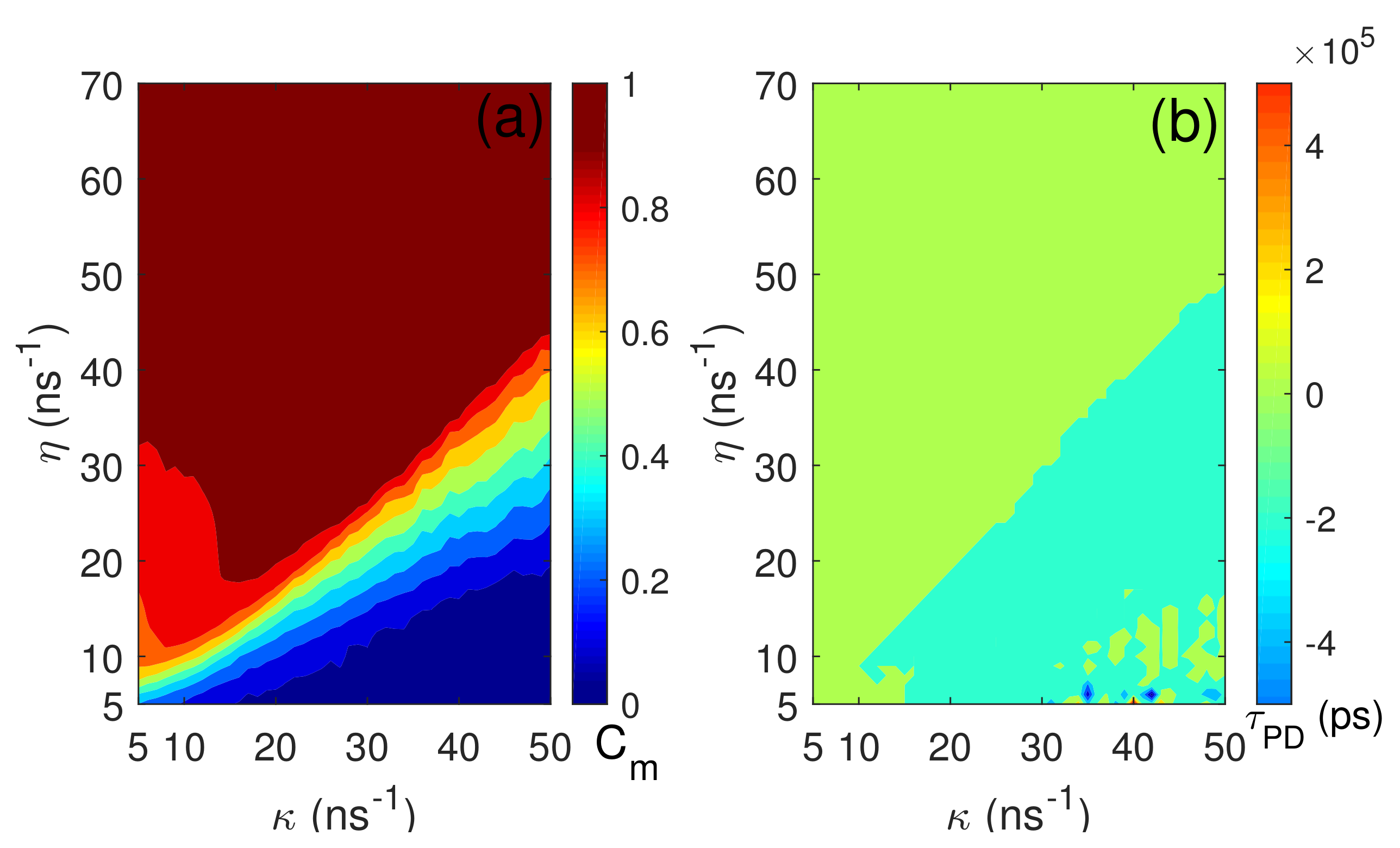
Additionally, the mapping of C m and the associated τ P D in the plane of TL’s feedback rate κ and injection rate η are shown in Figure 8. We kept the other parameters the same as in Figure 1. The dark red boundary in Figure 8a indicate that a good synchronization quality ( C m > 0 . 9 ) can be obtained between TL and RL, which is due to the larger injection rate. And in those regimes, the associated τ P D take positive values as well as found to decrease (light green boundary in Figure 8b) as the injection rate increases. It is evident from Figure 8a that the quality of synchronization also depends on the κ , wherein which for higher values of κ , stronger injection is a necessary condition to achieve good synchronization between TL and RL.

4. Secure Optical Communication

In this section, we investigate the effect of τ P D on the message encoding and decoding based on chaos synchronization between the transmitter and receiver laser. As described in the previous Section 3, the transmitter laser’s pump magnitude is modulated with a message and transmitted to the receiver laser. The message recovery is performed by subtracting the receiver laser output from the transmitted output signal and then filtering the difference using a fifth-order Butterworth filter.
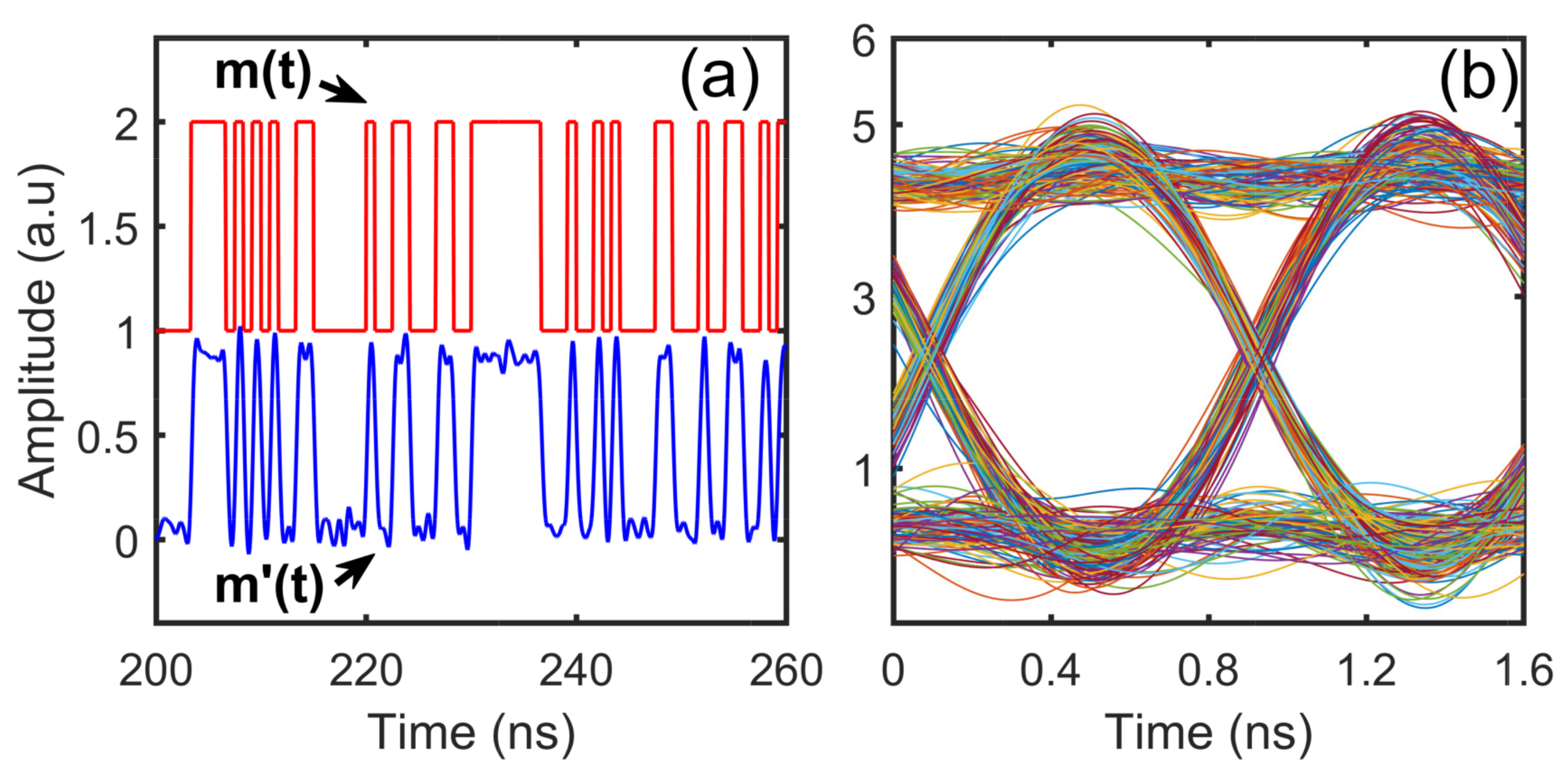
A digital message signal with 1.2 Gbit/s bit rate is encoded at the transmitter laser. In Figure 9a, we present the original message m ( t ) (red) together with the recovered message m ( t ) (blue). The eye diagram, Figure 9b, shows that the message is successfully recovered with less error, where the eye diagram is very open. Apart from the synchronization performance, the quality of the recovered message would also depend on the chaos pass filtering [54]. The recovered message is shown in Figure 9 obtained prior to the intra-cavity propagation delay τ P D correction in the receiver laser.
To quantify the recovered message quality, BER is evaluated and expressed as e x p ( Q 2 / 2 ) / 2 π Q . The quality factor is defined as Q = ξ 1 ξ 0 / σ 1 + σ 0 where ξ 1 ( ξ 0 ) is the mean power of bits “1” (“0”), and σ 1 ( σ 0 ) corresponding standard deviation. It must be stated that the lesser BER value indicates the message recovery quality is better in the communication system. The BER of the recovered message prior to the τ P D correction in the receiver laser is 5 . 43 × 10 12 . The evaluated intra-cavity propagation delay τ P D is corrected in receiver laser’s output and we repeated the message recovery process. Thus, the obtained BER value is found to be 4 . 10 × 10 12 , which is evidently lesser than that of the BER of the recovered message signal obtained prior to the τ P D correction to the receiver laser output. To further compare the influence of τ P D and communication performances with the other schemes such as chaos masking (CMA) and chaos modulation (CMO), the BER is measured for each of the schemes. For CMA scheme, the C m and τ P D are found to be 0.82 and 27.6 ps, respectively. The BER value prior to the τ P D correction is 4 . 70 × 10 3 , and after the correction it is 4 . 59 × 10 3 . In the case of CMO, the C m is measured to be 0.85 and the corresponding τ P D is 28.2 ps. And the BER value without (with) the τ P D correction is 1 . 28 × 10 1 ( 1 . 27 × 10 1 ). It is evident that the τ P D , although small value in relative scales, has a noticeable and measurable effect on the recovery of a message in all three schemes. To ascertain if τ P D correction is going to be a non-ignorable quantity in the recovery process we repeated this study for various injection rates and frequency detunings between TL and RL.
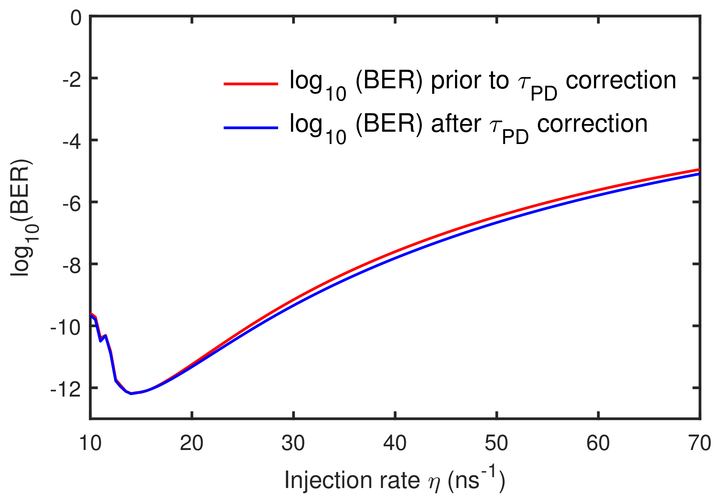
We focus our investigation on the influence of the intra-cavity propagation delay τ P D on message encoding/decoding for various injection rates η between the transmitter and receiver laser. The encoding message signal at 1.2 Gbit/s bit rate with a modulation depth of b = 0 . 2 , Δ f = 0 , and the injection rate η is varied from 10 ns 1 to 70 ns 1 . The effect of τ P D on the quality of message recovery with varying η is shown in Figure 10. For each of the values of η , the quality of signal recovery as evaluated in terms of BER, prior to (after) the τ P D correction is shown in a red (blue) trace. We make two inferences from Figure 10. First, the BER is found to decrease up to the injection rate of η = 17 ns 1 and BER increases for stronger injection. For stronger injection, the receiver tends to exactly reproduce the transmitter output, which consists of the chaotic output carrier together with the message signal. Hence, when stronger injection is applied, apart from the chaotic carrier subtraction, a part of the message signal itself will be eliminated in the process of decoding the signal [27,28]. Secondly, it is evident from Figure 10 that the BER value is consistently less (blue trace) if message recovery is carried out after the τ P D correction to the receiver’s output, which is implying that quality of the message recovery will improve if the intra-cavity propagation delay correction is incorporated in the receiver laser system.
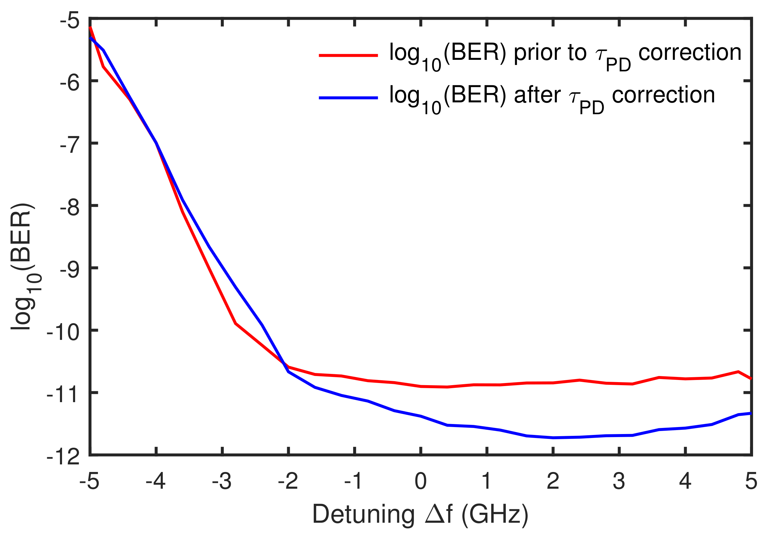
Next, we investigate the role of frequency detuning on quality of message recovery and thus the influence of intra-cavity propagation delay τ P D . The injection rate is kept as η = 15 ns 1 and varied frequency detuning Δ f . The obtained results are presented in Figure 11. It is evident from the figure that, the BER of the recovered message is found lesser near zero detuning. For Δ f range −2 GHz to −5 GHz, where the better correlation found between TL and RL (see Figure 7), the quality of message recovery is worse (BER is more) since the receiver exactly reproduces the transmitter chaotic carrier output together with the message signal [27,28]. As we have seen from Figure 7 that the synchronization quality is very sensitive while varying frequency detuning, where that affects message recovery excessively. The analysis of message recovery is restricted within the −5 GHz to +5 GHz detuning boundaries in the Figure 11 since RL is driven into the chaotic state only for Δ f within −5 GHz to +5 GHz. As far as the influence of τ P D in the message recovery is concerned, in comparison with the BER (red trace) prior to the τ P D correction, the BER is found to decrease (blue trace) after τ P D correction in the recovery process.
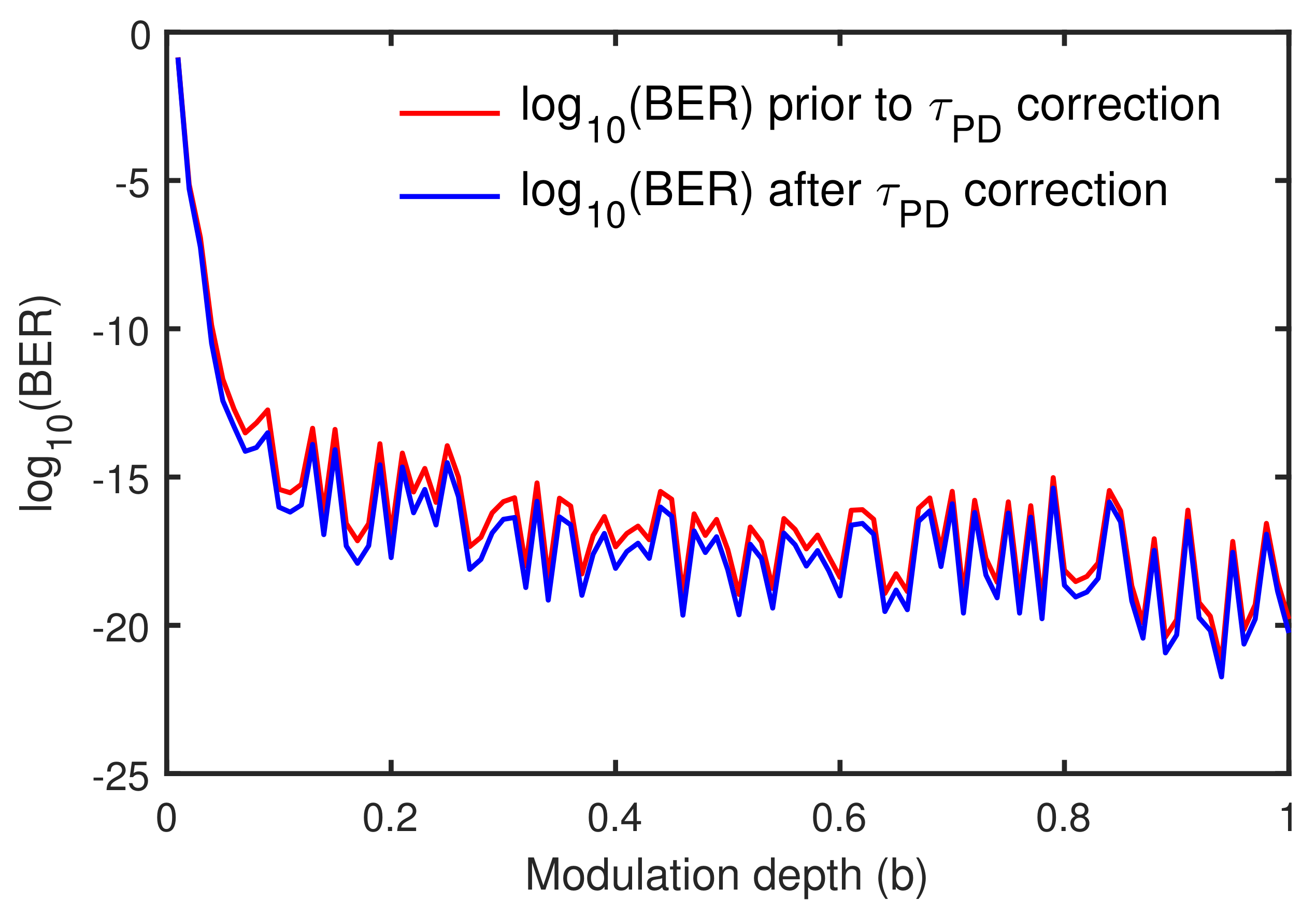
To further investigate the effect of intra-cavity propagation delay on communication performance, Figure 12 shows the BER of the recovered message for a different modulation depth of 1.2 Gbit/s bit rate message signal. Other parameters kept the same as in Figure 9. BER of the recovered message is evaluated for different message depth values, for before (red trace) and after (blue trace) the τ P D correction in the recovery process, and shown in Figure 12. Prior to the τ P D correction, as the message depth gradually increased from 0.01 to 1, the BER decreases dramatically from 0.12 to 5 . 29 × 10 21 . Moreover, there is a consistent improvement in the quality of message recovery (BER 0.12 to 1 . 80 × 10 21 ) after the τ P D correction (blue trace) as compared to the quality of signal recovery performed without the correction (red trace).
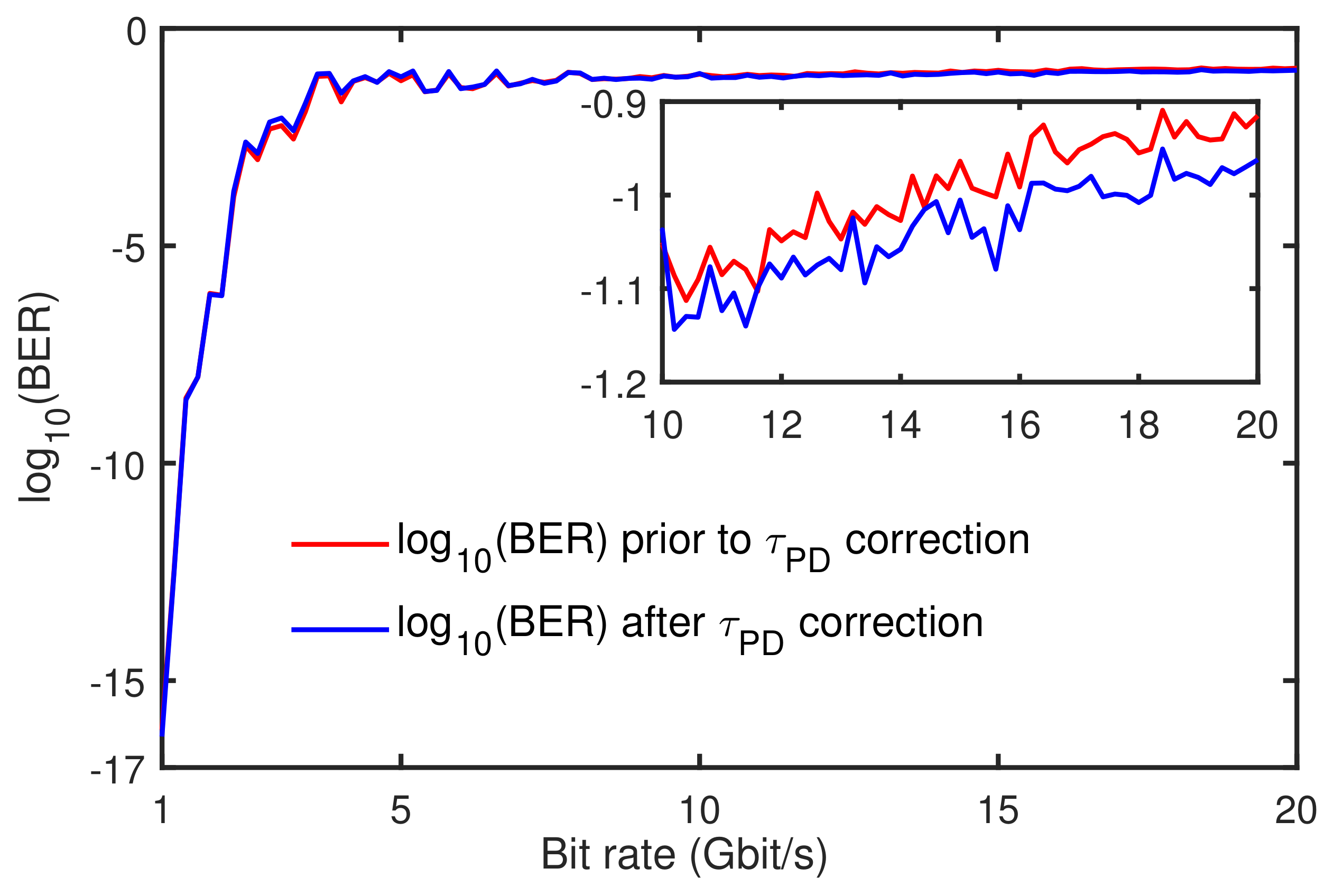
Figure 13 shows the BER of the recovered message for different message bit rates at modulation depth b = 0 . 2 . As shown in Figure 13, the BER is increased as the bit rate increases (blue and red trace) for both before and after the correction cases. The BER performance for lager message bit rate is worse than that for the lower case. For lower message bit rates (≤6 Gbit/s), the high-quality chaos communication is obtained, where the BER is sustained to be the order of 10 9 . As also noticed that the BER performance of the recovered message is improved (see inset of Figure 13) when incorporating the intra-cavity propagation delay correction in the message recovery process.
We observe that, considering BR = 1.2 Gbit/s with b = 0.2 in Figure 10, the quality of message recovery is modest in the region η between 12 n s 1 to 18 n s 1 for keeping Δ f = 0 and other lasers’ parameters same. Next in Figure 11 the message recovery quality is adequate and appropriate near zero detuning. In Figure 12, modulation depth beyond 0.05, the message recovery quality improves satisfactorily. Finally in Figure 13, it’s evident that bit rate less than 6 Gbit/s better quality of chaos communication is obtained.

5. Conclusions

To summarize, we have numerically shown the role of intra-cavity propagation delay in message encoding and decoding using chaotic semiconductor lasers. Based on the chaos shift keying scheme, a digital message signal of 1.2 Gbit/s bit rate with a modulation depth of 0.2 is encoded at the transmitter laser and is recovered at the receiver by comparing its output with the transmitter laser. We found that despite the magnitude of intra-cavity propagation delay τ P D is less, it has an impact on the quality of message recovery. The influence of τ P D and the associated bit error rate of the recovered message signal is carried out for different values of injection rates. The results convey that, τ P D correction in the recovery process does improve the quality of message recovery. Next, the influence of frequency detuning on τ P D and thus on the message recovery is investigated. The quality of message recovery shows an improvement after the τ P D correction. Furthermore, we have presented the effect of τ P D on the quality of message recovery for the range of modulation depths and message bit rates. We note that recovered message quality found to increase (BER is less) after the τ P D correction for each value of modulation depths and bit rates. Although, the τ P D magnitude (order of pico-seconds) is much less, it does have an effect in the signal recovery, where we find the effect is also less. Nevertheless, we emphasize that, in long-haul communication, where more than one receiver laser is considered in the communication system, the τ P D would have noticeable effect, since it is a dynamically arising time delay in the system and has an accumulative nature as TL output propagates through multiple receiver lasers in the cascading configuration [48]. However, the study of τ P D influence in the long-haul communication system is beyond the scope of our present study. In conclusion, we can emphasize that the intra-cavity propagation delay correction needs to be incorporated to the receiver laser in order to achieve a better quality of message recovery in a system of synchronized chaotic semiconductor diode lasers.

Author Contributions

E.J. was responsible for the numerical simulation, analyzing the results and writing of the paper. S.S. was responsible for the conceptualization. Y.-S.H., X.T., X.-D.L. and T.D. were responsible for writing and revising the manuscript. G.-Q.X. and Z.-M.W. were responsible for the discussion of the results and reviewing/editing/proof-reading of the manuscript.

Funding

This work was supported in part by the National Natural Science Foundation of China under Grant 61575163, Grant 61775184, and Grant 61875167.

Conflicts of Interest

The authors declare no conflict of interest.

References

  1. VanWiggeren, G.D.; Roy, R. Communication with Chaotic Lasers. Science 1998, 279, 1198–1200. [Google Scholar] [CrossRef] [PubMed]
  2. Takiguchi, Y.; Ohyagi, K.; Ohtsubo, J. Bandwidth-enhanced chaos synchronization in strongly injection-locked semiconductor lasers with optical feedback. Opt. Lett. 2003, 28, 319–321. [Google Scholar] [CrossRef]
  3. Paul, J.; Lee, M.W.; Shore, K.A. 3.5-GHz signal transmission in an all-optical chaotic communication scheme using 1550-nm diode lasers. IEEE Photon. Technol. Lett. 2005, 17, 920–922. [Google Scholar] [CrossRef]
  4. Argyris, A.; Syvridis, D.; Larger, L.; Annovazzi-Lodi, V.; Colet, P.; Fischer, I.; Garcia-Ojalvo, J.; Mirasso, C.R.; Pesquera, L.; Shore, K.A. Chaos-based communications at high bit rates using commercial fibre-optic links. Nature 2005, 438, 343–346. [Google Scholar] [CrossRef] [PubMed]
  5. Argyris, A.; Hamacher, M.; Chlouverakis, K.E.; Bogris, A.; Syvridis, D. Photonic Integrated Device for Chaos Applications in Communications. Phys. Rev. Lett. 2008, 100, 194101. [Google Scholar] [CrossRef]
  6. Hong, Y.; Lee, M.W.; Shore, K.A. Optimised Message Extraction in Laser Diode Based Optical Chaos Communications. IEEE J. Quantum Electron. 2010, 46, 253–257. [Google Scholar] [CrossRef]
  7. Jiang, N.; Pan, W.; Luo, B.; Yan, L.; Xiang, S.; Yang, L.; Zheng, D.; Li, N. Influence of injection current on the synchronization and communication performance of closed-loop chaotic semiconductor lasers. Opt. Lett. 2011, 36, 3197–3199. [Google Scholar] [CrossRef]
  8. Li, N.; Pan, W.; Luo, B.; Yan, L.; Zou, X.; Jiang, N.; Xiang, S. High bit rate fiber-optic transmission using a four-chaotic-semiconductor-laser scheme. IEEE Photon. Tech. Lett. 2012, 24, 1072–1074. [Google Scholar] [CrossRef]
  9. Sciamanna, M.; Shore, K.A. Physics and applications of laser diode chaos. Nature Photon. 2015, 9, 151–162. [Google Scholar] [CrossRef]
  10. Li, N.; Susanto, H.; Cemlyn, B.; Henning, I.D.; Adams, M.J. Secure communication systems based on chaos in optically pumped spin-VCSELs. Opt. Lett. 2017, 42, 3494–3497. [Google Scholar] [CrossRef]
  11. Ke, J.; Yi, L.; Xia, G.Q.; Hu, W. Chaotic optical communications over 100-km fiber transmission at 30-Gb/s bit rate. Opt. Lett. 2018, 43, 1323–1326. [Google Scholar] [CrossRef] [PubMed]
  12. Pecora, L.M.; Carroll, T.L. Synchronization in chaotic systems. Phys. Rev. Lett. 1990, 64, 821–824. [Google Scholar] [CrossRef] [PubMed]
  13. Lang, R.; Kobayashi, K. External optical feedback effects on semiconductor injection laser properties. IEEE J. Quantum Electron. 1980, 16, 347–355. [Google Scholar] [CrossRef]
  14. Heil, T.; Fischer, I.; Elsasser, W. Chaos synchronization and spontaneous symmetry-breaking in symmetrically delay-coupled semiconductor lasers. Phys. Rev. Lett. 2001, 86, 795–798. [Google Scholar] [CrossRef] [PubMed]
  15. Locquet, A.; Masoller, C.; Mirasso, C.R. Synchronization regimes of optical-feedback-induced chaos in unidirectionally coupled semiconductor lasers. Phys. Rev. E 2002, 65, 056205. [Google Scholar] [CrossRef] [PubMed]
  16. Locquet, A.; Masoller, C.; Megret, P.; Blondel, M. Comparison of two types of synchronization of external-cavity semiconductor lasers. Opt. Lett. 2002, 27, 31–33. [Google Scholar] [CrossRef] [PubMed]
  17. Flynn, S.P.; Spencer, P.S.; Sivaprakasam, S.; Pierce, I.; Shore, K.A. Identification of the optimum time-delay for chaos synchronization regimes of semiconductor lasers. IEEE J. Quantum Electron. 2006, 42, 427–434. [Google Scholar] [CrossRef]
  18. Cuomo, K.M.; Oppenheim, A.V. Circuit implementation of synchronized chaos with applications to communications. Phys. Rev. Lett. 1993, 71, 65–68. [Google Scholar] [CrossRef]
  19. Larger, L.; Goedgebuer, J.P.; Delorme, F. Optical encryption system using hyperchaos generated by an optoelectronic wavelength oscillator. Phys. Rev. E 1998, 57, 6618–6624. [Google Scholar] [CrossRef]
  20. Sanchez-Diaz, A.; Mirasso, C.R.; Colet, P.; Garcia-Fernandez, P. Encoded Gbit/s digital communications with synchronized chaotic semiconductor lasers. IEEE J. Quantum Electron. 1999, 35, 292–297. [Google Scholar] [CrossRef]
  21. Uchida, A.; Yoshimori, S.; Shinozuka, M.; Ogawa, T.; Kannari, F. Chaotic on–off keying for secure communications. Opt. Lett. 2001, 26, 866–868. [Google Scholar] [CrossRef] [PubMed]
  22. Tang, S.; Liu, J.M. Message encoding–decoding at 2.5 Gbits/s through synchronization of chaotic pulsing semiconductor lasers. Opt. Lett. 2001, 26, 1843–1845. [Google Scholar] [CrossRef] [PubMed]
  23. Ohtsubo, J. Chaos synchronization and chaotic signal masking in semiconductor lasers with optical feedback. IEEE J. Quantum Electron. 2002, 38, 1141–1154. [Google Scholar] [CrossRef]
  24. Liu, Y.; Davis, P.; Takiguchi, Y.; Aida, T.; Saito, S.; Liu, J.M. Injection locking and synchronization of periodic and chaotic signals in semiconductor lasers. IEEE J. Quantum Electron. 2003, 39, 269–278. [Google Scholar]
  25. Nguimdo, R.M.; Colet, P.; Larger, L.; Pesquera, L. Digital Key for Chaos Communication Performing Time Delay Concealment. Phys. Rev. Lett. 2011, 107, 034103. [Google Scholar] [CrossRef] [PubMed]
  26. Tang, S.; Liu, J.M. Effects of message encoding and decoding on synchronized chaotic optical communications. IEEE J. Quantum Electron. 2003, 39, 1468–1474. [Google Scholar] [CrossRef]
  27. Argyris, A.; Syvridis, D. Performance of open-loop all-optical chaotic communication systems under strong injection condition. IEEE Photon. Tech. Lett. 2004, 22, 1272–1279. [Google Scholar] [CrossRef]
  28. Li, X.; Pan, W.; Luo, B.; Ma, D. Mismatch robustness and security of chaotic optical communications based on injection-locking chaos synchronization. IEEE J. Quantum Electron. 2006, 42, 953–960. [Google Scholar] [CrossRef]
  29. Ke, J.; Yi, L.; Hou, T.; Hu, Y.; Xia, G.; Hu, W. Time Delay Concealment in Feedback Chaotic Systems with Dispersion in Loop. IEEE Photonics J. 2017, 9, 7200808. [Google Scholar] [CrossRef]
  30. Rontani, D.; Locquet, A.; Sciamanna, M.; Citrin, D.S. Loss of time-delay signature in the chaotic output of a semiconductor laser with optical feedback. Opt. Lett. 2007, 32, 2960–2962. [Google Scholar] [CrossRef]
  31. Wu, J.G.; Xia, G.Q.; Wu, Z.M. Suppression of time delay signatures of chaotic output in a semiconductor laser with double optical feedback. Opt. Exp. 2009, 17, 20124–20133. [Google Scholar] [CrossRef] [PubMed]
  32. Porte, X.; D’Huys, O.; Jüngling, T.; Brunner, D.; Soriano, M.C.; Fischer, I. Autocorrelation properties of chaotic delay dynamical systems: A study on semiconductor lasers. Phys. Rev. E 2014, 90, 052911. [Google Scholar] [CrossRef] [PubMed]
  33. Colet, P.; Roy, R. Digital communication with synchronized chaotic lasers. Opt. Lett. 1994, 19, 2056–2058. [Google Scholar] [CrossRef] [PubMed]
  34. Sivaprakasam, S.; Shore, K.A. Message encoding and decoding using chaotic external-cavity diode lasers. IEEE J. Quantum Electron. 2000, 36, 35–39. [Google Scholar] [CrossRef]
  35. Liu, J.M.; Chen, H.F.; Tang, S. Synchronized chaotic optical communications at high bit rates. IEEE J. Quantum Electron. 2002, 38, 1184–1196. [Google Scholar]
  36. Larger, L.; Goedgebuer, J.P.; Merolla, J.M. Chaotic oscillator in wavelength: a new setup for investigating differential difference equations describing nonlinear dynamics. IEEE J. Quantum Electron. 1998, 34, 594–601. [Google Scholar] [CrossRef]
  37. Luo, L.G.; Chu, P.L.; Liu, H.F. 1-GHz optical communication system using chaos in erbium-doped fiber lasers. IEEE Photon. Technol. Lett. 2000, 12, 269–271. [Google Scholar] [CrossRef]
  38. Abarbanel, H.D.I.; Kennel, M.B.; Illing, L.; Tang, S.; Chen, H.F.; Liu, J.M. Synchronization and communication using semiconductor lasers with optoelectronic feedback. IEEE J. Quantum Electron. 2001, 37, 1301–1311. [Google Scholar] [CrossRef]
  39. Mirasso, C.R.; Colet, P.; Garcia-Fernandez, P. Synchronization of chaotic semiconductor lasers: application to encoded communications. IEEE Photon. Technol. Lett. 1996, 8, 299–301. [Google Scholar] [CrossRef]
  40. Sivaprakasam, S.; Shore, K.A. Critical signal strength for effective decoding in diode laser chaotic optical communications. Phys. Rev. E 2000, 61, 5997–5999. [Google Scholar] [CrossRef]
  41. Rogister, F.; Locquet, A.; Pieroux, D.; Sciamanna, M.; Deparis, O.; Mégret, P.; Blondel, M. Secure communication scheme using chaotic laser diodes subject to incoherent optical feedback and incoherent optical injection. Opt. Lett. 2001, 26, 1486–1488. [Google Scholar] [CrossRef] [PubMed]
  42. Mirasso, C.R.; Mulet, J.; Masoller, C. Chaos shift-keying encryption in chaotic external-cavity semiconductor lasers using a single-receiver scheme. IEEE Photon. Technol. Lett. 2002, 14, 456–458. [Google Scholar] [CrossRef]
  43. Annovazzi-Lodi, V.; Donati, S.; Scire, A. Synchronization of chaotic injected-laser systems and its application to optical cryptography. IEEE J. Quantum Electron. 1996, 32, 953–959. [Google Scholar] [CrossRef]
  44. Annovazzi-Lodi, V.; Donati, S.; Scire, A. Synchronization of chaotic lasers by optical feedback for cryptographic applications. IEEE J. Quantum Electron. 1997, 33, 1449–1454. [Google Scholar] [CrossRef]
  45. Johnson, G.A.; Mar, D.J.; Carroll, T.L.; Pecora, L.M. Synchronization and Imposed Bifurcations in the Presence of Large Parameter Mismatch. Phys. Rev. Lett. 1998, 80, 3956–3959. [Google Scholar] [CrossRef]
  46. Annovazzi-Lodi, V.; Benedetti, M.; Merlo, S.; Norgia, M.; Provinzano, B. Optical chaos masking of video signals. IEEE Photon. Technol. Lett. 2005, 17, 1995–1997. [Google Scholar] [CrossRef]
  47. Ohtsubo, J. Semiconductor Lasers: Stability, Instability and Chaos, 4th ed.; Springer International: New York, NY, USA, 2017. [Google Scholar]
  48. Jayaprasath, E.; Sivaprakasam, S. Accumulation of intra-cavity propagation delay in synchronized cascaded chaotic semiconductor lasers. IEEE J. Quantum Electron. 2013, 49, 1026–1033. [Google Scholar] [CrossRef]
  49. Jayaprasath, E.; Sivaprakasam, S. Dynamical regimes and intracavity propagation delay in external cavity semiconductor diode lasers. Pramana J. Phys. 2017, 89, 76. [Google Scholar] [CrossRef]
  50. Jayaprasath, E.; Wu, Z.M.; Sivaprakasam, S.; Xia, G.Q. Observation of additional delayed-time in chaos synchronization of uni-directionally coupled VCSELs. Chaos Interdiscip. J. Nonlinear Sci. 2018, 28, 123103. [Google Scholar] [CrossRef]
  51. Li, N.; Pan, W.; Luo, B.; Zou, X.; Xiang, S. Enhanced two-channel optical chaotic communication using isochronous synchronization. IEEE J. Sel. Top. Quantum Electron. 2013, 19, 0600109. [Google Scholar]
  52. Soriano, M.C.; García-Ojalvo, J.; Mirasso, C.R.; Fischer, I. Complex photonics: Dynamics and applications of delay-coupled semiconductors lasers. Rev. Mod. Phys. 2013, 85, 421–470. [Google Scholar] [CrossRef]
  53. Murakami, A.; Kawashima, K.; Atsuki, K. Cavity resonance shift and bandwidth enhancement in semiconductor lasers with strong light injection. IEEE J. Quantum Electron. 2003, 39, 1196–1204. [Google Scholar] [CrossRef]
  54. Murakami, A.; Shore, K.A. Chaos-pass filtering in injection-locked semiconductor lasers. Phys. Rev. A 2005, 72, 053810. [Google Scholar] [CrossRef]
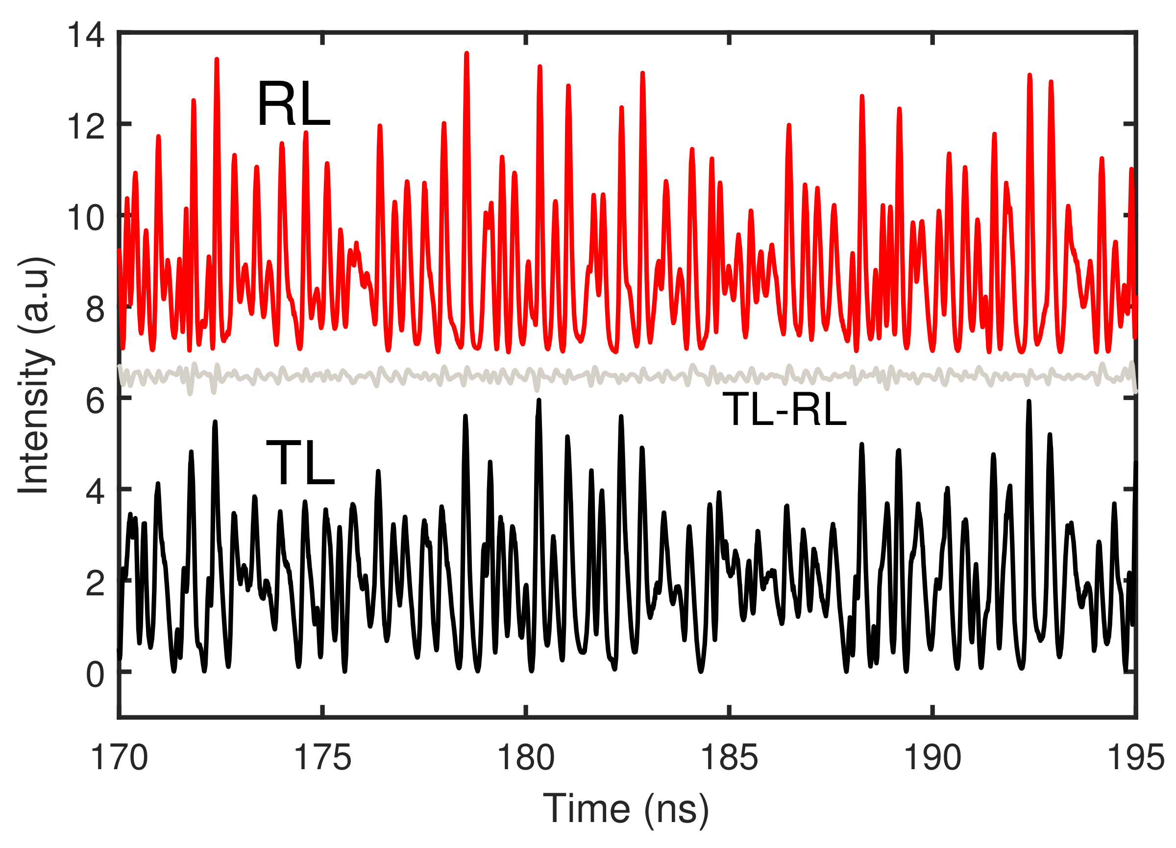
Figure 1. Time traces of the transmitter and receiver lasers: The black (red) traces correspond to TL (RL) output (chaotic intensity including message signal) respectively for J m = 1 . 10 I t h , J R = 1 . 08 I t h , κ = 9 ns 1 , η = 15 ns 1 , Δ f = 0 , τ e x t = 10 ns, and τ f = 0 . The grey trace corresponds to the difference between the intensities of the transmitter and receiver lasers.
Photonics 06 00049 g001
Figure 2. Chaotic attractors in the phase space of the laser’s intensity output and the carrier density. (a) Transmitter laser and (b) Receiver laser.
Photonics 06 00049 g002
Figure 3. Cross-correlation coefficient between transmitter and receiver laser for κ = 9 ns 1 , η = 15 ns 1 , Δ f = 0 , τ e x t = 10 ns, and τ f = 0 . The inset figure shows the expanded version of CC plot near zero in time scale. The intra-cavity propagation delay τ P D is found to be 32.8 ps.
Photonics 06 00049 g003
Figure 4. Maximum cross-correlation coefficient C m map in the injection parameters (frequency detuning Δ f , injection rate η ) plane for keeping κ = 9 ns 1 , τ e x t = 10 ns, and τ f = 0 .
Photonics 06 00049 g004
Figure 5. Intra-cavity propagation delay τ P D map in the injection parameters (frequency detuning Δ f , injection rate η ) plane for keeping κ = 9 ns 1 , τ e x t = 10 ns, and τ f = 0 .
Photonics 06 00049 g005
Figure 6. Transmitter-receiver maximum correlation coefficient C m (red trace) and the associated intra-cavity propagation delay τ P D (blue trace) as a function of injection rate for keeping Δ f = 0 , κ = 9 ns 1 , τ e x t = 10 ns, and τ f = 0 .
Photonics 06 00049 g006
Figure 7. Transmitter-receiver maximum correlation coefficient C m (red trace) and the associated intra-cavity propagation delay τ P D (blue trace) as a function of frequency detuning for keeping η = 15 ns 1 , κ = 9 ns 1 , τ e x t = 10 ns, and τ f = 0 .
Photonics 06 00049 g007
Figure 8. Mapping of C m (a) and the corresponding τ P D (b), in the plane of κ and η for keeping other parameters as J m = 1 . 10 I t h , J R = 1 . 08 I t h , τ e x t = 10 ns, τ f = 0 , and Δ f = 0 .
Photonics 06 00049 g008
Figure 9. Results of unidirectional message encoding and decoding using CSK scheme for J m = 1 . 10 I t h , J R = 1 . 08 I t h , κ = 9 ns 1 , η = 15 ns 1 , Δ f = 0 , τ e x t = 10 ns, and τ f = 0 under transmitter-receiver configuration. (a) The original message m ( t ) (red) and the recovered one m ( t ) (blue), and (b) the eye diagram of the recovered message. The digital message transmitted at 1.2 Gbit/s bit rate with b = 0 . 2 modulation depth.
Photonics 06 00049 g009
Figure 10. Estimation of BER values of the recovered messages as a function of injection rate for BR = 1.2 Gbit/s, b = 0 . 2 , and Δ f = 0 . Red and blue traces correspond to BER value prior to and after the intra-cavity propagation delay τ P D correction, respectively, in the receiver laser.
Photonics 06 00049 g010
Figure 11. Estimation of BER values of the recovered messages as a function of frequency detuning for BR = 1.2 Gbit/s, b = 0 . 2 , and η = 15 ns 1 . Red (blue) trace correspond to BER value prior to (after) the τ P D correction in the receiver laser.
Photonics 06 00049 g011
Figure 12. Estimation of BER values of the recovered messages as a function of a modulation depth for BR = 1.2Gbit/s message signal. Red (blue) trace correspond to BER value prior to (after) the τ P D correction in the receiver laser.
Photonics 06 00049 g012
Figure 13. Estimation of BER values of the recovered messages for different bit rates at modulation depth b = 0 . 2 . Red and blue traces correspond to BER value prior to and after the τ P D correction, respectively, in the receiver laser.
Photonics 06 00049 g013