Article

300 GHz Optoelectronic Transmitter Combining Integrated Photonics and Electronic Multipliers for Wireless Communication

by
Muhsin Ali
1,*,
Jose Manuel Pérez-Escudero
2,
Robinson-Cruzoe Guzmán-Martínez
1,
Mu-Chieh Lo
1,
Iñigo Ederra
2,
Ramón Gonzalo
2,
Luis Enrique García-Muñoz
3,
Gabriel Santamaría
3,
Daniel Segovia-Vargas
3,
Frédéric van Dijk
4 and
Guillermo Carpintero
1
1
Departamento de Tecnología Electrónica, Universidad Carlos III de Madrid, 28911 Leganés, Madrid, Spain
2
Departamento de Ingeniería Eléctrica y Electrónica, Universidad Pública de Navarra, 31006 Pamplona, Navarra, Spain
3
Departamento de Teoría de Señal, Universidad Carlos III de Madrid, 28911 Leganés, Madrid, Spain
4
III-V Lab, Campus de Polytechnique, Avenue Augustin Fresnel 1, 91767 Palaiseau CEDEX, France
*
Author to whom correspondence should be addressed.
Photonics 2019, 6(2), 35; https://doi.org/10.3390/photonics6020035
Submission received: 6 February 2019 / Revised: 8 March 2019 / Accepted: 15 March 2019 / Published: 27 March 2019
(This article belongs to the Special Issue Terahertz Photonics)

Abstract

:
THz communications systems at carrier frequencies above 200 GHz are the key to enable next-generation mobile communication networks with 100 Gbit/s wireless data rates. One of the key questions is, which carrier frequency generation technique will be the most suitable. This is currently addressed by two separate approaches, electronics-based and photonics-based. We present in this paper a truly microwave photonic approach that benefits from the main key features of each, bandwidth, tunability, stability and fiber compatibility from photonics and power handling capability from the electronics. It is based on a Photonic Local Oscillator (PLO), generating a 100 GHz frequency, fed into an electronic frequency multiplier. A high speed uni-travelling carrier photodiode (UTC-PD) provides the 100 GHz PLO for Schottky tripler diodes, generating 300 GHz signal. To feed the UTC-PD, we present a photonic integrated mode locked laser source. According to the simulations and measurements, the developed transmitter can produce a maximum of 12 μW of THz power at 280 GHz.

1. Introduction

The development of Beyond 5G next-generation mobile communication networks is addressing the bandwidth challenge, leaping from the 20 MHz available within the frequency range between 800 MHz and 2.6 GHz, and beyond the current 5 GHz available at different millimeter-wave (mm-Wave) bands between 71 GHz to 95 GHz [1]. The prospective data rate for wireless communications in the marketplace will be 100 Gbit/s within 10 years [2], critical in the future as new multimedia standards increase their resolution. The signal coming out of an high definition (HD) camera has a bit-rate of 1.5 Gb/s, requiring compression techniques to fit it through the limited bandwidth of broadcast channels 19 Mb/s and discarding real time transmission. The current 4K standard has four times the pixels of 1080p HD, and compression is not an option as it will look no better than today’s HDTV and the associated delay will not allow live broadcasting. The solution is the use of carrier frequencies at frequency bands where broad bandwidth with low atmospheric absorption are still available. These are at the high end of the mm-Wave band, above 220 GHz, with the added advantage that bands above 275 GHz have not yet been allocated at specific active services, and standardization efforts are becoming very active [3].
Anticipating this evolution, several groups of researchers have been investigating terahertz (THz) communications systems at carrier frequencies above 200 GHz, being one of the key aspects the carrier frequency generation technique. Currently two different approaches are being used. One is the electronics-based approach, now enabling most of the 100–150-GHz band wireless links. The highest real time data rate transmission demonstration using electronics-approach achieved 20 Gb/s on a 220 GHz carrier frequency [4]. This approach attracts significant interest owing to the features of compact size, room temperature operation and potential for chip integration. In this approach, frequency multiplication has turned out to be the most common method to generate THz frequency signals [5]. The other, is the photonic-approach, a technology that is always leading the access to the higher frequencies [6]. Photonic technologies have already reported real time transmission at 48 Gb/s at 300 GHz based on On-Off Keyed (OOK) modulation using polarization multiplexing in a multiple input multiple output system [7].
The photonics-based approach to wireless carrier frequency generation presents a key advantage as enabler of the desired convergence of wired (optical fiber) and wireless networks. Recently, a wireless-over-fibre system using multiband transmission at 200 GHz to achieve an overall downlink data rate of 100 Gb/s has been reported, with 10 Gb/s OOK uplink data returned over the same fiber [8]. These demonstrations clearly show two issues:
(a)
THz communication systems are capable of delivering high-rate data over wireless links, but due to the intrinsic high propagation loss at higher carrier frequencies and the low power generated at these frequencies by photonic sources, the transmission distances achieved so far are typically in the range of about 10 m at 409 GHz [9], and
(b)
The electronics-based and photonics-based approaches have been evolving separately, competing with each other, with few efforts to combine both worlds in a truly microwave photonic approach that would benefit from the main key features of each; bandwidth, tunability, stability and fiber compatibility from photonics and power handling capability from the electronics.
Within this paper we present the efforts to develop terahertz-wave transmitter module based on photonic-electronic co-integration to deliver a room temperature, compact and efficient module. Figure 1 shows the overall block diagram of the proposed system. It features an optoelectronic transmitter and a photonic integrated signal source. The transmitter section is composed of two sub-modules; a photonic local oscillator (PLO) and a frequency tripler. The novel feature of the transmitter module is that it combines a high power UTC-PD with an electronic multiplier diode. Small active-area photodiodes are required to obtain the wide bandwidth required for photonic THz generation, but beyond 3-dB cut-off frequency (usually 100 GHz) their response exhibit sharp roll-off. While their small size means that the optical power applied must be limited in order to prevent damage due to thermal dissipation at high photocurrents. An output power of 0 dBm (1 mW) at 120 GHz, with a flat frequency response over the microwave F-band (90–140 GHz), has been demonstrated from a UTC-PD fabricated using a photonic integrated process flow [10]. We therefore use this UTC-PD to generate a 100 GHz local oscillator (LO) signal by optoelectronic conversion of a photonic signal generated by a semiconductor mode-locked laser.
To increase the output frequency, we have explored feeding the output (LO) from the UTC-PD to a Schottky diode frequency tripler that generates the 300 GHz output signal within a WR03 (220 GHz to 325 GHz) waveguide. This approach follows the classical solid-state electronic devices used during the last two decades to up-convert the signal provided by the available stable solid-state sources in microwave frequency range by multiplier chains, formed with cascaded Schottky doublers and/or triplers. These multipliers have been showing power handling capability, delivering 20 mW output power at 193 GHz with an efficiency of nearly 8% [11]. We believe that this approach can outperform an all-photonic ones using a power combiner at the output of two UTC-PDs, combining their outputs to yield more than 1 mW at 300 GHz only when both were close to device destruction [12].

2. 300 GHz Optoelectronic Transmitter

In this section we discuss the design of transmitter under study along with the simulation and measurements of PLO and frequency multiplier sub-modules. The tripler unit is a balanced frequency tripler featuring anti-parallel pair of Schottky diodes. The passive circuit is designed in grounded coplanar waveguide, where the Schottky diodes and the UTC-PD are placed. The substrate used for the design is 130 µm thick Rogers RT/Duroid 5880 (εr = 2.2 and tanδ = 0.009). Multiple vias are used to assure contact between the coplanar and bottom grounds, improving the behavior of the transmission line. The optoelectronic integration, PLO generation and tripler sub-modules are explained in subsequent sub-sections.

2.1. Photonic Local Oscillator

One of the key components in this proposed 300 GHz transmitter is high speed photodiode (PD). The UTC-PD has been a dominant type of photodiode for generation of high power mm-Wave and sub-THz carrier signals using photonic techniques. Due to separate absorption and carrier generation regions, the space-charge effect is reduced and results in higher saturation power levels as compared with PIN photodetectors. The UTC-PD used for this work was manufactured at III-V Lab [10], with 50 Ω coplanar electrical output. It has an active area of 4 × 15 μm2, and an output RF power of up to 1 mW at 120 GHz. The photodiode chip, fabricated on 120 μm thick indium phosphide (InP) substrate, was mounted on an aluminum nitride (AlN) subcarrier for improved heat dissipation.
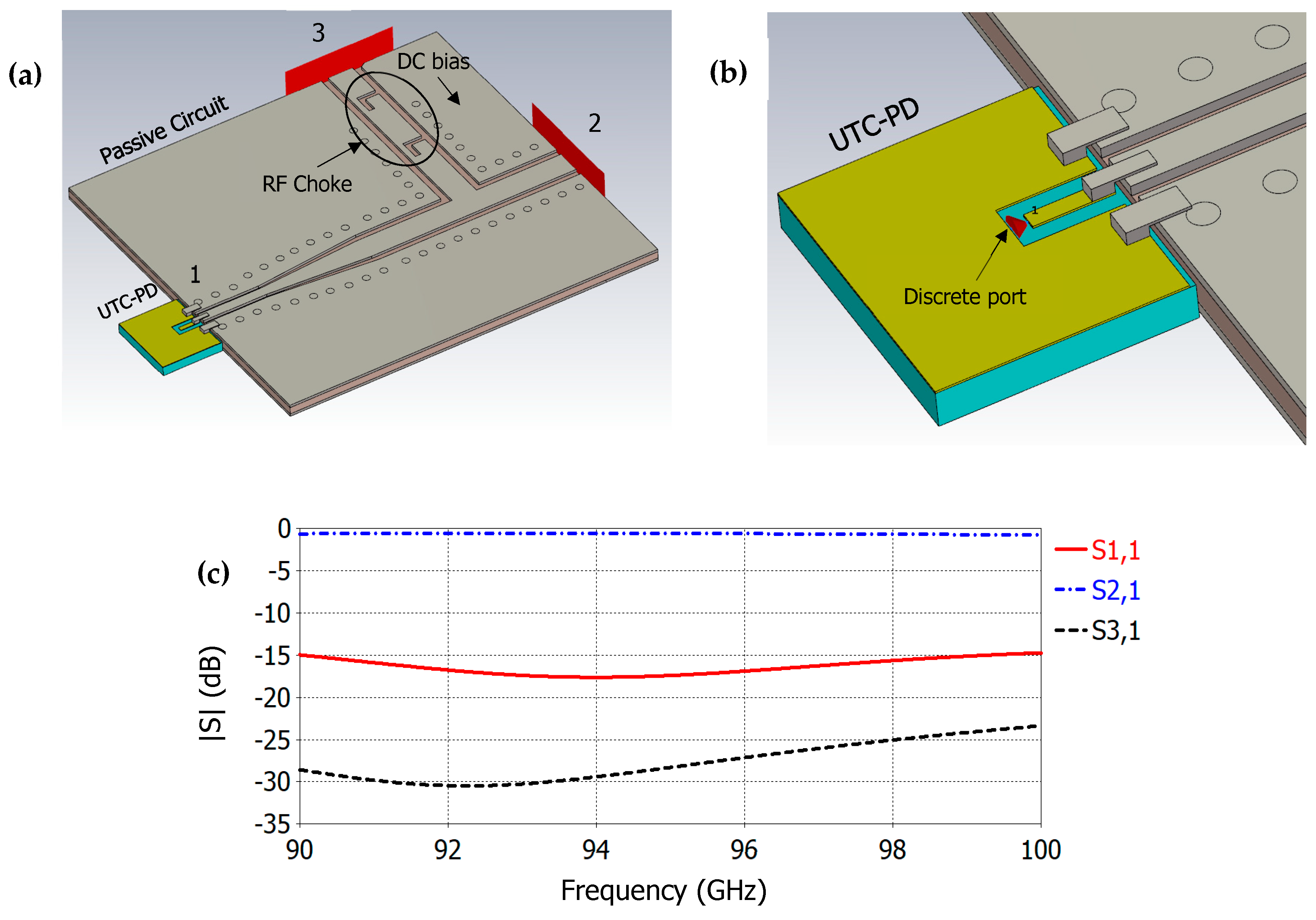
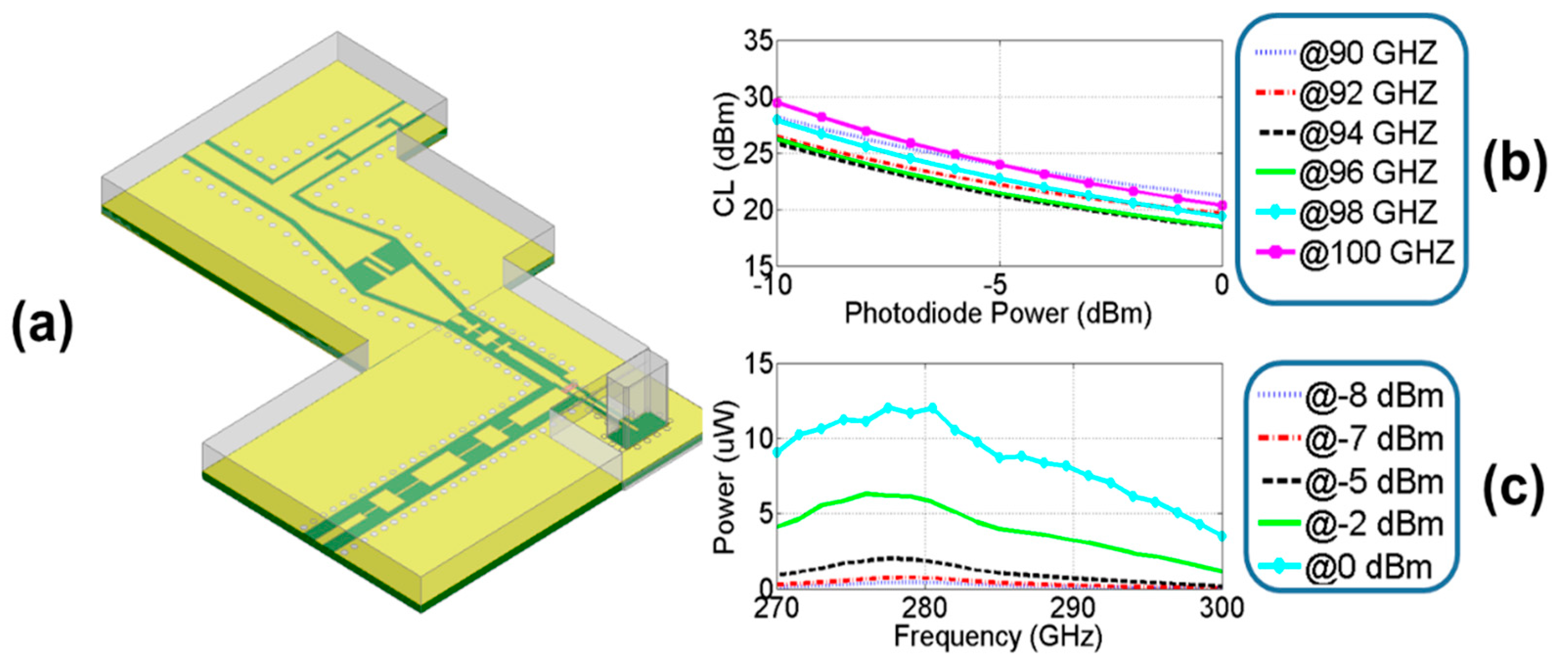
Figure 2a shows the full-wave electromagnetic model of the input section of transmitter passive circuit, including RF choke filter, integrated with a UTC-PD. The RF coupling between the PD and the passive circuit is addressed by using silver-filled epoxy, which avoids the inductance of the bond wires when wire bonding is used. The UTC-PD chip is modelled as 5 μm thick gold coplanar waveguide (CPW) on InP with 50 Ω impedance, as shown in Figure 2b. To achieve closest approximation, the conductive epoxy is realized as slabs of silver. The simulated frequency response |S| is plotted in Figure 2c. It can be noticed that the overall insertion loss (S2,1) between the input (UTC-PD) and passive circuit stays less than 1 dB in complete LO frequency range (90–100 GHz). While the isolation (S3,1) between input port and DC port is better than 23 dB.
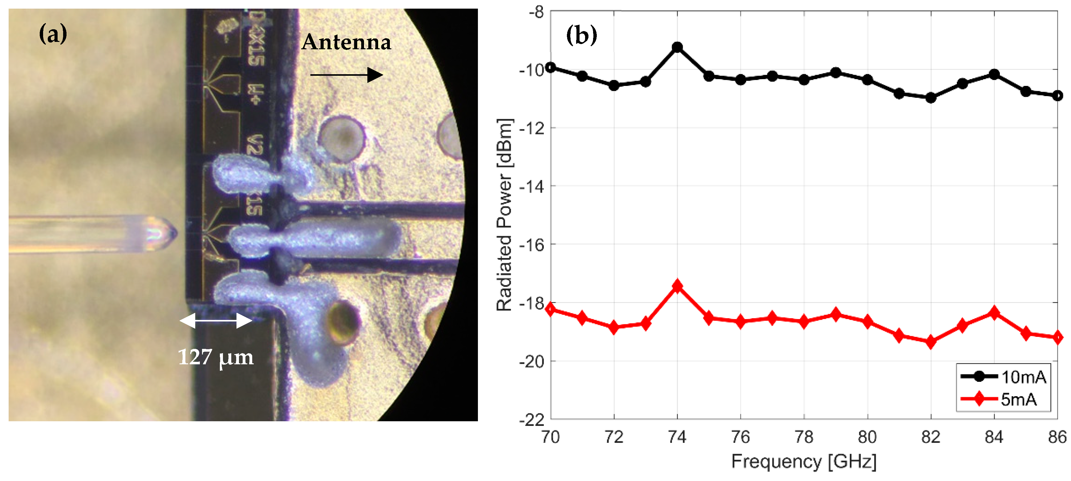
To validate the RF coupling technique and measure the LO power available at the input of tripler diodes, we integrated the UTC-PD with a planar antenna, with coplanar pads at the input, that radiates in the E-band (71–86 GHz). Figure 3a shows the micrograph of the assembly of the photodiode with test antenna, along with a lensed fiber. We use optical heterodyne method to generate the mm-Wave carrier signal using two free running external cavity lasers (ECL). The coupled RF power is radiated by the antenna and measured in free space by a calibrated THz absolute power meter (Thomas Keating). Figure 3b shows the measured power at DC photocurrent levels of 5 mA and 10 mA. The reserve bias voltage for the UTC-PD was 3 V. It’s important to notice here that power fluctuations in the whole frequency range are below ±1-dB, showing the robustness of the hybrid assembly of UTC-PD. A maximum power of −9.1 dBm (121.2 μW) is observed at 74 GHz. The photocurrent in this experiment was limited to 10 mA. Comparing these results with the on-chip measurements [10] we estimate a coupling loss of around 5 dB, that will give us maximum of −5 dBm RF power at in 90–100 GHz range for the LO input of the tripler diode. This test demonstrated the suitability of the proposed optoelectronic integration technique. It must be noted that the frequency limitation in this measurement came from the fractional bandwidth of the antenna employed.

2.2. Frequency Tipler

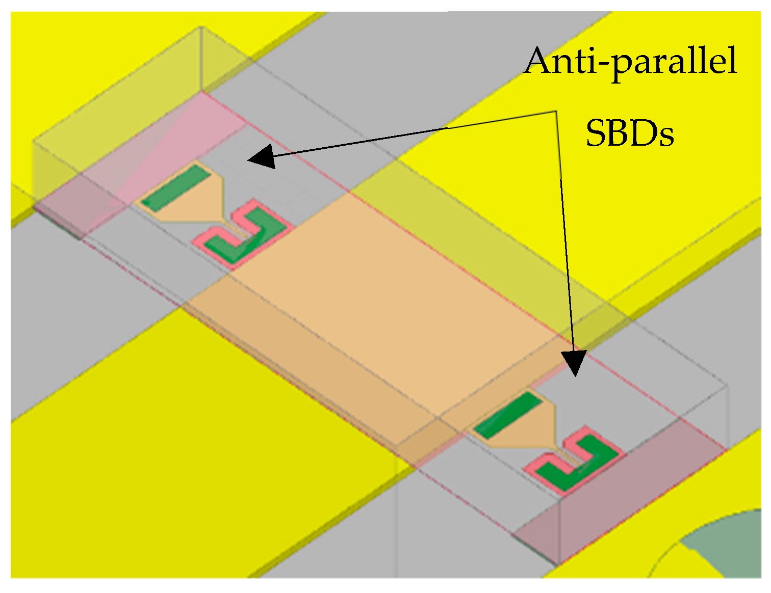
A balanced frequency tripler [13] featuring an antiparallel pair of gallium arsenide (GaAs) based Schottky varactor diodes has been designed to generate an output signal at 300 GHz. The chosen topology generates only odd harmonics and suppress the even harmonics, which implies a more efficient design for frequency triplers. The diodes used for the tripler are UMS Schottky diodes with 1 × 3 µm2 anode dimension. Their layers are defined by the UMS foundry manufacturing process. This junction performs a resistance of 7.3 Ω, a junction capacitance 5.14 fF and the ideality factor is n = 1.2. The diode cutoff frequency is 3 THz, which allows 300 GHz operation. The diode chip is about 200 × 80 µm2. A 3D perspective view of the antiparallel diode configuration can be seen in Figure 4.
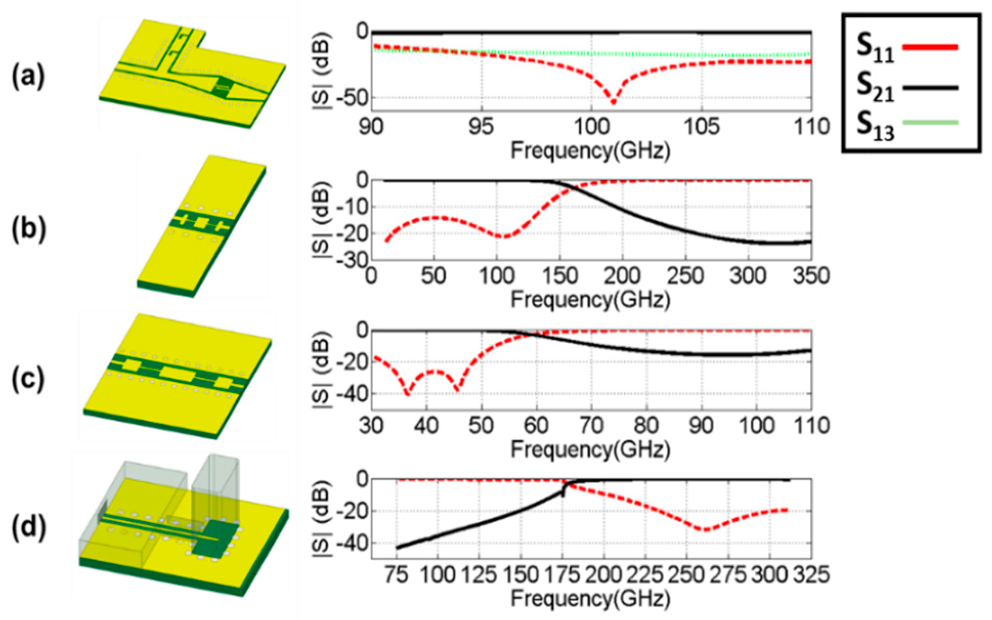
For the proper biasing of the two active chips with different voltage sources, a Bias-T is employed, which consists of a low pass filter (LPF) to apply the DC signal and a DC-block (capacitor) that rejects the DC and allows to pass only the high frequency signal. An LPF must be placed between the Schottky diodes and the photodiode to reject the harmonics produced by the tripler. In this case, since narrow band operation is required a stepped impedance LPF is chosen due to the simplicity of design. At the output of this passive circuit, a transition to WR-3 waveguide is designed using an E-Plane probe. This transition also acts as a high pass filter, since the photodiode W-band signal is below cutoff frequency of the WR3. The Schottky diodes are biased as was commented. Therefore, another low pass filter is necessary in order to block the RF and LO signals and avoid leakage through this bias path. 3D-views of the mentioned passive components and their predicted responses using the full wave simulation package Ansys HFSS are shown in Figure 5.
A combination of simulation with the commercial software packages Ansys HFSS and Keysight ADS has been used in order to obtain a more accurate response of the multiplier diode and take into account its parasitic capacitance and resistance. The diode’s embedding impedance has been optimized by adjusting the distance from the filters to different coplanar waveguide sections. The full 3D model used for simulation and the obtained results can be seen in Figure 6. The dielectric substrate is enclosed in a metal package, modelled by an electric boundary. The height of the lid is chosen to be 400 µm. This height does not disturb the fields since it is not a multiple of λ/2. The S-parameters of this circuit, obtained with HFSS, are exported and used in the harmonic balance simulation of ADS.
In Figure 6b we can observe the conversion loss (CL) of the frequency tripler. It has been analyzed for different values of LO frequencies to determine the bandwidth of the frequency tripler and the output power of the system. The photodiode output power, fed into the Schottky diodes, is swept from 0 to −10 dBm. This analysis helps to evaluate the degradation of the tripler behavior when the input power is too low and estimate the limits of operation. The bias voltage has been optimized to 0.15 V. It can be clearly noticed that for all values of LO, the CL is very stable in frequency and increases as the photodiode output power is reduced. Figure 6c shows the calculated output power of the 300 GHz tripler vs. LO frequency at different input power levels. For 0 dBm we obtain the best case, where the CL is between 18 and 21 dB for the whole bandwidth. The conversion loss decreases for lower input powers. For −5 dBm we obtain that the conversion loss goes from 21 to 24 dB and the worst case for −10 dB performs around 28 dB. The output power is, therefore, above 4 µW for the whole bandwidth for an input power of 0 dBm with a best case of 12.0 µW. Considering −5 dBm case, the maximum available LO power, we estimate that a maximum of 2 μW of THz power can be obtained from the proposed optoelectronic transmitter.

3. Photonic Integrated Signal Source

Passive mode locking (PML) based on III-V semiconductor lasers PIC generating optical frequency combs (OFC) have been increasingly attracting attention in recent years, due to its chip-scaled compactness and simplicity of DC operation. Especially, passive mode-locked laser (MLL) diodes at repetition rates in mm-Wave and THz ranges have been considered as promising in communications, spectroscopy, and sensing [14,15]. However, in most cases, an extremely high repetition rate (>100 GHz) in an MLL corresponds to only a few hundreds of µm cavity length (<400 µm). For this reason, harmonic mode locking (HML) schemes have been investigated to produce multiple pulses per round trip in a sufficiently long cavity, thus pushing the repetition rate beyond the low-GHz fundamental cavity round trip frequency [16]. HML is achieved by means of colliding pulse mode locking (ML) [17], coupled cavity ML [18] and methods based on the wavelength selectivity of distributed Bragg reflector (DBR) grating [19]. In colliding pulse ML, one saturable absorber (SA) is placed at the midpoint of the cavity, where two counter-propagating pulses circulate and collide, producing a train of pulses at repetition rates that are twice the fundamental round trip frequency. Evolving from colliding pulse ML, multiple colliding pulse ML features and multiple SAs concatenated with gain sections, for repetition rates multiplication >2 as has been extensively investigated [20,21]. Recently, a new class of on-chip broadband reflector based on the multimode interference (MMI) principle has been proposed [22] and demonstrated its wide applicability [23,24]. Such multimode interference reflectors (MIRs) are simple to create in lithography with greater fabrication tolerance to replace DBRs and cleaved facets. Furthermore, they can be placed anywhere on a chip, and the transmitted light is maniputable on-chip to fulfill more functionalities [25].
In this section we present a monolithically integrated MIR-based quantum-well MLLD, developed and fabricated within a multi-project wafer run in InP-based active-passive generic foundry. It utilizes multiple colliding pulse ML principle to generate a fourth harmonic 100 GHz optical frequency comb, from a 25 GHz fundamental repetition rate, to be used as an input to drive the PLO described above.

3.1. Device Description

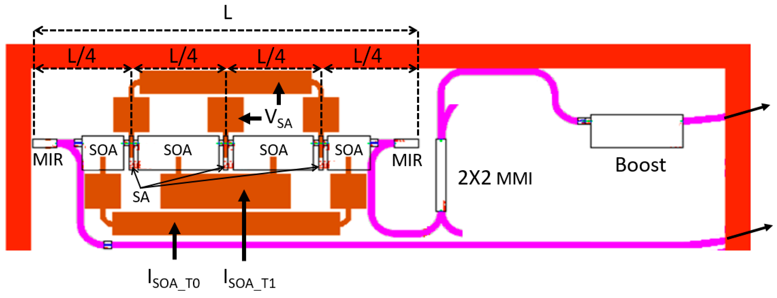
Figure 7 shows the schematic layout of the multiple colliding pulse MLL. The Fabry-Pérot laser cavity is formed with a pair of MIRs, in which there are four gain sections (semiconductor optical amplifiers, SOAs) separated by three SA sections placed at every quarter of the cavity length. The on-chip MIRs define a cavity length, L, of around 1.66 mm, corresponding to a fundamental round trip frequency of 25 GHz, while every quarter section (L/4) is around 0.42 mm long. In the design, the length of all three SAs is 20 µm. The two inner gain sections (~350 µm) are much longer than the two outer gain sections ~180 µm. Electrical isolation sections were inserted between every two adjacent SOAs to avoid undesirable back current flows.
At each end of the cavity, one 2-port MIR terminates the straight waveguide at one port defining the overall Fabry-Pérot cavity length, but also carrying light out of the cavity through the other port. The two MIRs are ~55 µm long, having two ports with ~40% transmissivity and ~40% reflectivity, based on the multimode interference principle and internal etched reflection walls. While the chip can yield optical power up to a few 100s of μW, an on-chip boost amplifier is included to push the output power up to a few mW.

3.2. Characterization Results

The PIC is mounted on an AlN subcarrier, which has several DC and coplanar RF tracks for biasing of the active components of the device. The DC pads extensions of the gain sections and the metal layer of the boost are wire bonded to the DC tracks on the submount, while the pads extensions of the SAs are wire bonded to the RF tracks. The subcarrier is placed on a cooper chuck of a probe station where it is stabilized in temperature. The working temperature is set to 16 °C for all the measurements. To control the integrated device all SAs are connected to an external voltage source VSA, while the outer and inner gain sections are fed by current sources ISOA_T0 and ISOA_T1, respectively. Three DC probes are physically contacted on the respective DC tracks. A ground-signal-ground probe head is contacted on the RF track for the SAs in order to inject an RF signal and to get the hybrid regime condition.
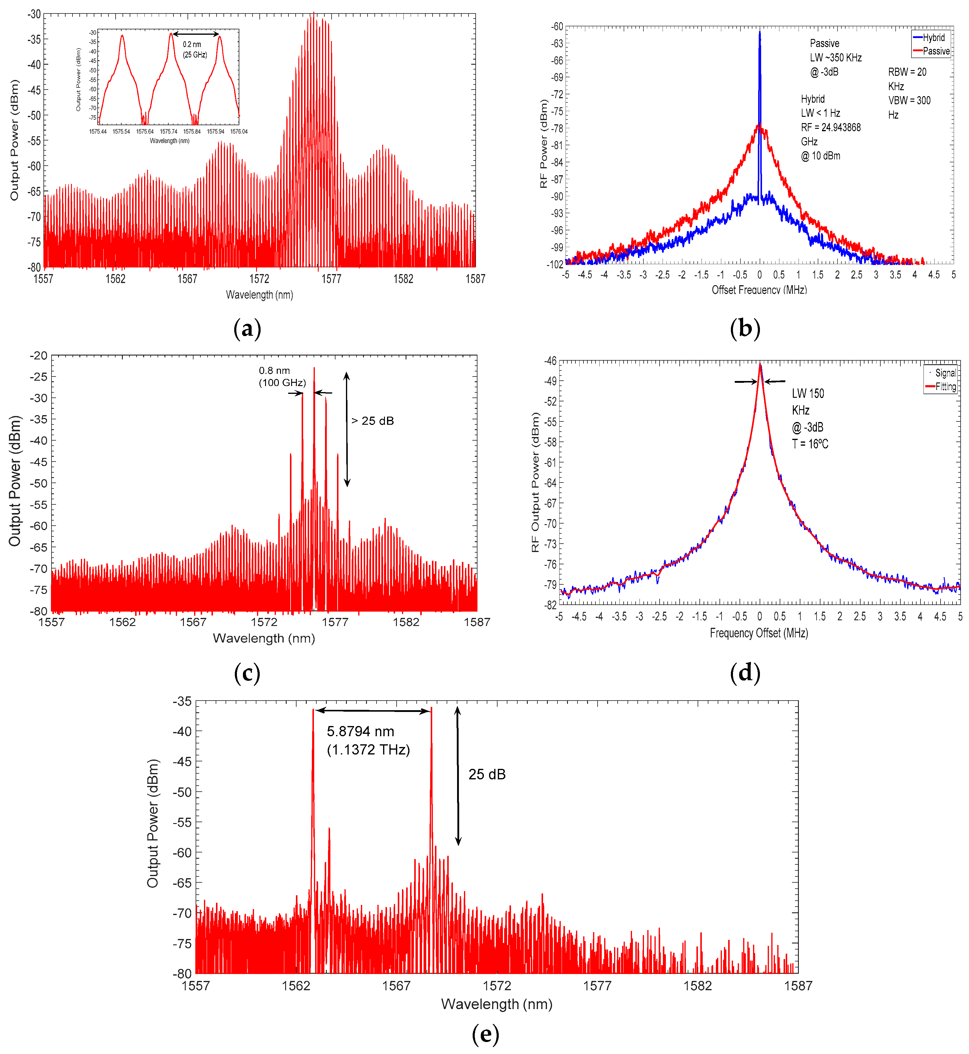
For evaluating the spectral performance in the optical and electrical domains, we plot the spectra in Figure 8. Table 1 details the biasing conditions at which the optical spectra, Figure 8a,c,e, were obtained. In Figure 8a, twenty comb lines are obtained near 1575 nm with a 0.2 nm spacing between every two modes, equivalent to 25 GHz repetition rate in frequency domain. An inset on the left side of the optical spectrum shows the modal spacing for three optical modes.
Regarding Figure 8c, the optical spectrum shows seven comb lines and the modal spacing in between is around 0.8 nm, which is equivalent to 100 GHz repetition rate. The seven lasing modes constitute an optical frequency comb which exhibits a suppression ratio of ~25 dB, with respect to the level of the suppressed modes that are associated with the fundamental cavity round-trip frequency of 25 GHz. As can be observed, one every four modes are lasing, confirming the multiple colliding frequency multiplication regime.
The electrical linewidth in passive regime is measured at the fundamental frequency (25 GHz), shown in Figure 8b with an offset from 25 GHz, as well as the fourth harmonic, shown in Figure 8d with an offset from 100 GHz. The measured electrical linewidth is ~350 KHz at 25 GHz and ~150 KHz at 100 GHz. In the hybrid regime, we inject an RF signal of 24.943868 GHz and with a power level of 10 dBm in the outer SAs.
By changing the bias conditions for gain sections and the SAs, dual wavelength emission with a frequency spacing of 1.1372 THz is achieved. The optical spectrum response is shown in Figure 8e. When the laser is operated with higher bias levels, it generates higher-order harmonics. In the THz region, the spectral separation between optical lines is too large (>8 nm) so that the number of optical lines becomes smaller. In such conditions, only two optical modes instead of a huge number of evenly spaced comb lines take place. It shows that the on-chip device presented here can also provide THz-rate emissions.

4. Conclusions

We presented a truly microwave photonic approach for the generation of THz carrier signals for high speed wireless communications. With the help of full-wave simulations and measurements, we demonstrated the feasibility of integrating a high speed InP photodiode chip with GaAs Schottky multiplier diodes on a single substrate. To the best of our knowledge, this is first demonstration of such a photonic-electronic hybrid integration technique. This combination of photonic and electronic active devices allows to benefit from the intrinsic advantages of each of the two technologies such as tunability, fiber compatibility and power handling capability. Based on the analysis presented, a maximum output power of 12 μW in best case is estimated in WR03 frequency band. The relatively low power is calculated mainly because of the conversion losses in the tripler didoes. However, the proposed concept allows to easily integrate a 100 GHz LNA chip in the device instead of 300 GHz one, given the commercial availability of mm-Wave devices. By doing so, a decent amount of THz power can be achieved at 300 GHz, depending on number of amplification stages. This will complement the low output power of the photomixers that currently operate up to mm-Wave range.

Author Contributions

Conceptualization, G.C. and M.A.; formal analysis, I.E, R.G.; investigation, M.A., J.M.P.-E., R.C.G., G.S. and M.-C.L.; resources, F.v.D.; writing—original draft preparation, M.A.; writing—review and editing, G.C.; supervision, G.C., L.E.G.-M. and I.E.; funding acquisition, G.C., F.v.D., D.S.-V

Funding

This work has been supported by European Union’s Horizon 2020 research and innovation programme under the Marie Sklodowska-Curie grant agreement No. 642355 FiWiN5G, as well as by Spanish Ministerio de Economia y Competitividad through Programa Estatal de Investigación, Desarrollo e Inovación Orientada a los Retos de la Sociedad (grant iTWIT, TEC2016-76997-C3-3-R).

Acknowledgments

The authors wish to thank Sacher Lasertechnik GmbH (www.sacher-laser.com) for lending Lion Tunable External Cavity Diode Laser used for experiments in this work.

Conflicts of Interest

The authors declare no conflict of interest.

References

  1. Rappaport, T.S.; Sun, S.; Mayzus, R.; Zhao, H.; Azar, Y.; Wang, K.; Wong, G.N.; Schulz, J.K.; Samimi, M.; Gutierrez, F. Millimeter wave mobile communications for 5G cellular: It will work! IEEE Access 2013, 1, 335–349. [Google Scholar] [CrossRef]
  2. White Paper, The Zettabyte Era: Trends and Analysis, CISCO. Available online: https://files.ifi.uzh.ch/hilty/t/Literature_by_RQs/RQ%20102/2015_Cisco_Zettabyte_Era.pdf (accessed on 1 January 2019).
  3. Kürner, T.; Priebe, S. Towards THz communications-status in research, standardization and regulation. J. Infrared Millim. Terahertz Waves 2014, 35, 53–62. [Google Scholar] [CrossRef]
  4. Kallfass, I.; Antes, J.; Schneider, T.; Kurz, F.; Lopez-Diaz, D.; Diebold, S.; Massler, H.; Leuther, A.; Tessmann, A. All active MMIC-based wireless communication at 220 GHz. IEEE Trans. Terahertz Sci. Technol. 2011, 1, 477–487. [Google Scholar] [CrossRef]
  5. Chattopadhyay, G. Technology, capabilities, and performance of low power terahertz sources. IEEE Trans. Terahertz Sci. Technol. 2011, 1, 33–53. [Google Scholar] [CrossRef]
  6. Nagatsuma, T.; Ducournau, G.; Renaud, C.C. Advances in terahertz communications accelerated by photonics. Nat. Photonics 2016, 10, 371. [Google Scholar] [CrossRef]
  7. Nagatsuma, T.; Horiguchi, S.; Minamikata, Y.; Yoshimizu, Y.; Hisatake, S.; Kuwano, S.; Yoshimoto, N.; Terada, J.; Takahashi, H. Terahertz wireless communications based on photonics technologies. Opt. Express 2013, 21, 23736–23747. [Google Scholar] [CrossRef]
  8. Shams, H.; Shao, T.; Fice, M.J.; Anandarajah, P.M.; Renaud, C.C.; Van Dijk, F.; Barry, L.P.; Seeds, A.J. 100 Gb/s Multicarrier THz Wireless Transmission System with High Frequency Stability Based on a Gain-Switched Laser Comb Source. IEEE Photonics J. 2015, 3, 1–11. [Google Scholar] [CrossRef]
  9. Jia, S.; Lo, M.C.; Zhang, L.; Ozolins, O.; Udalcovs, A.; Kong, D.; Pang, X.; Yu, X.; Xiao, S.; Popov, S.; et al. Integrated Dual-DFB Laser for 408 GHz Carrier Generation Enabling 131 Gbit/s Wireless Transmission over 10.7 Meters. In Proceedings of the Optical Fiber Communication Conference (OFC), San Diego, CA, USA, 2–8 March 2019. paper Th1C. [Google Scholar]
  10. Rouvalis, E.; Chtioui, M.; Tran, M.; Lelarge, F.; van Dijk, F.; Fice, M.J.; Renaud, C.C.; Carpintero, G.; Seeds, A.J. High-speed photodiodes for InP-based photonic integrated circuits. Opt. Express 2012, 20, 9172–9177. [Google Scholar] [CrossRef] [PubMed]
  11. Chen, Z.; Wang, H.; Alderman, B.; Huggard, P.; Zhang, B.; Fan, Y. 190 GHz high power input frequency doubler based on Schottky diodes and AlN substrate. IEICE Electron. Express 2016, 3, 20160981. [Google Scholar] [CrossRef]
  12. Song, H.-J.; Ajito, K.; Muramoto, Y.; Wakatsuki, A.; Nagatsuma, T.; Kukutsu, N. Uni-travelling-carrier photodiode module generating 300 GHz power greater than 1 mW. IEEE Microw. Wirel. Compon. Lett. 2012, 22, 363–365. [Google Scholar] [CrossRef]
  13. Maestrini, A.; Thomas, B.; Wang, H.; Jung, C.; Treuttel, J.; Jin, Y.; Chattopadhyay, G.; Mehdi, I.; Beaudin, G. Schottky diode-based terahertz frequency multipliers and mixers. C. R. Phys. 2010, 11, 480–495. [Google Scholar] [CrossRef]
  14. Avrutin, E.; Marsh, J.; Portnoi, E. Monolithic and multi-gigahertz mode-locked semiconductor lasers: constructions, experiments, models and applications. IEEE Proc.-Optoelectron. 2000, 147, 251–278. [Google Scholar] [CrossRef]
  15. Lo, M.-C.; Martínez, R.C.-G.; Carpintero, G. Monolithic mode-locked laser-based optical frequency comb for OFDM integrated on InP generic technology platform. In Proceedings of the Optical Fiber Communication Conference, San Diego, CA, USA, 11–15 March 2018. paper Th1I–1. [Google Scholar]
  16. Marsh, J.H.; Hou, L. Mode-locked laser diodes and their monolithic integration. IEEE J. Sel. Top. Quantum Electron. 2017, 23, 1–11. [Google Scholar] [CrossRef]
  17. Chen, Y.K.; Wu, M.C.; Tanbun-Ek, T.; Logan, R.A.; Chin, M.A. Subpicosecond monolithic colliding-pulse mode-locked multiple quantum well lasers. Appl. Phys. Lett. 1991, 58, 1253–1255. [Google Scholar] [CrossRef]
  18. Avrutin, E.A.; Marsh, J.H.; Arnold, J.M.; Krauss, T.F.; Pottinger, H.; la Rue, R.M.D. Analysis of harmonic (sub) THz passive mode-locking in monolithic compound cavity Fabry-Perot and ring laser diodes. IEE Proc. Optoelectron. 1999, 146, 55–61. [Google Scholar] [CrossRef]
  19. Arahira, S.; Oshiba, S.; Matsui, Y.; Kunii, T.; Ogawa, Y. Terahertz-rate optical pulse generation from a passively mode-locked semiconductor laser diode. Opt. Lett. 1994, 19, 834–836. [Google Scholar] [CrossRef]
  20. Katagiri, Y.; Takada, A. A harmonic colliding-pulse mode-locked semiconductor laser for stable subterahertz pulse generation. IEEE Photonics Technol. Lett. 1997, 9, 1442–1444. [Google Scholar] [CrossRef]
  21. Martins-Filho, J.F.; Avrutin, E.A.; Ironside, C.N.; Roberts, J.S. Monolithic multiple colliding pulse mode-locked quantum-well lasers, experiment and theory. IEEE J. Sel. Top. Quantum Electron. 1995, 1, 539–551. [Google Scholar] [CrossRef]
  22. Kleijn, E.; Smit, M.K.; Leijtens, X.J. Multimode interference reflectors: A new class of components for photonic integrated circuits. J. Light. Technol. 2013, 31, 3055–3063. [Google Scholar] [CrossRef]
  23. Stopinski, S.; Malinowski, M.; Piramidowicz, R.; Kazmierski, C.; Smit, M.K.; Leijtens, X.J. Photonic integrated multichannel wdm modulators for data read-out units. J. Light. Technol. 2014, 3879–3887. [Google Scholar] [CrossRef]
  24. Morrissey, P.E.; Kelly, N.; Dernaika, M.; Caro, L.; Yang, H.; Peters, F.H. Coupled cavity single-mode laser based on regrowth-free integrated MMI reflectors. IEEE Photonics Technol. Lett. 2016, 28, 1313–1316. [Google Scholar] [CrossRef]
  25. Lo, M.-C.; Guzmán, R.; Gordón, C.; Carpintero, G. Mode-locked laser with pulse interleavers in a monolithic photonic integrated circuit for millimeter wave and terahertz carrier generation. Opt. Lett. 2017, 42, 1532–1535. [Google Scholar] [CrossRef] [PubMed]
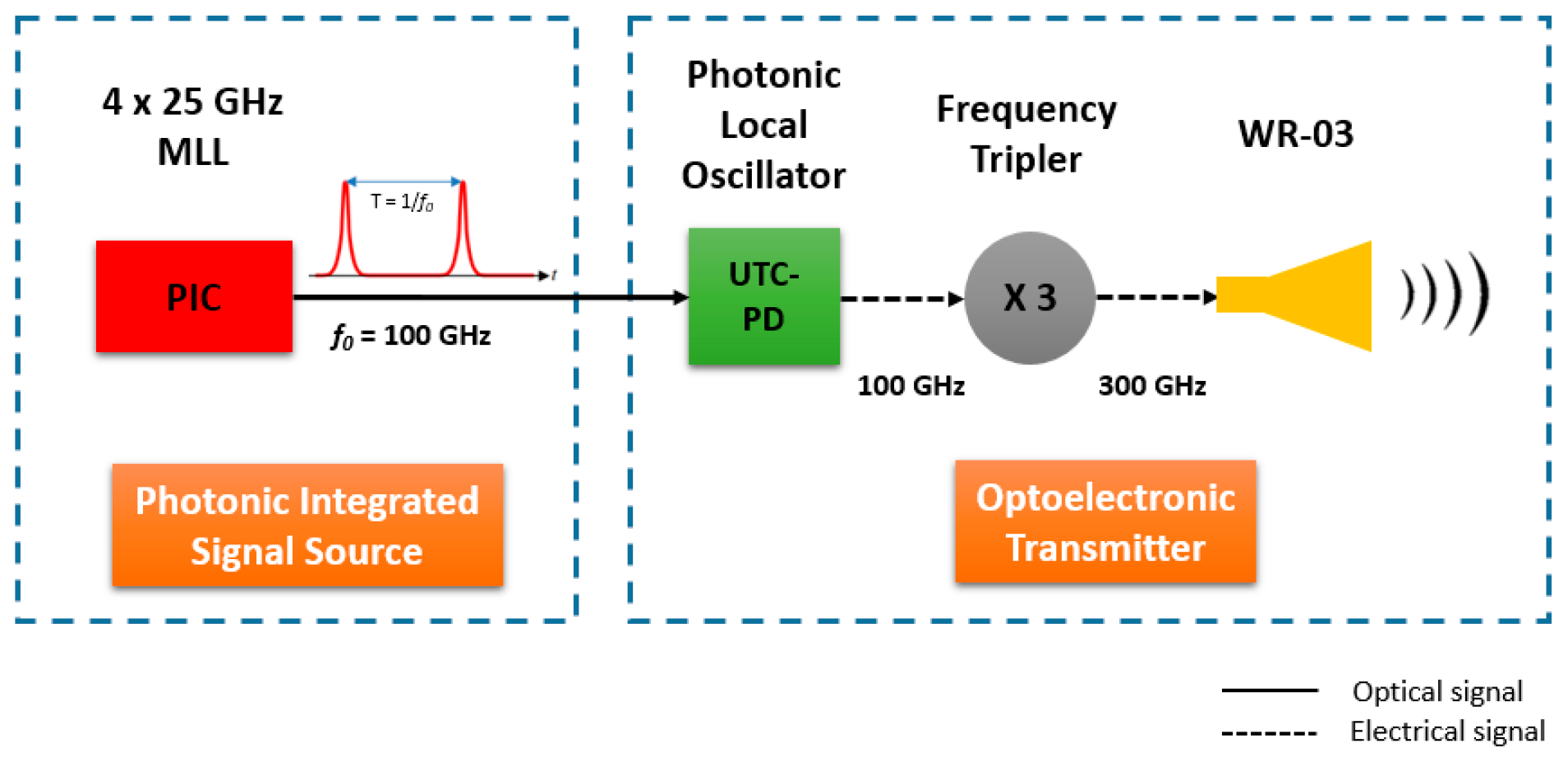
Figure 1. Block diagram of the 300 GHz optoelectronic transmitter based on UTC-PD and Schottky tripler diode technology, fed by a photonic integrated signal source. MLL: Mode-locked laser; PIC: Photonic integrated circuit; UTC-PD: Uni-travelling carrier photodiode; WR-03: Rectangular waveguide 03.
Photonics 06 00035 g001
Figure 2. (a) 3D perspective view of UTC-PD integrated to tripler passive circuit, (b) close-up view of UTC-PD 50 Ω coplanar structure excited by a discrete port providing 100 GHz LO signal and (c) simulated frequency response |S|.
Photonics 06 00035 g002
Figure 3. (a) Micrograph of test structure showing UTC-PD chip with coplanar pads integrated with planar antenna, along with a lensed fiber coupling and (b) measured radiated power in E-Band at bias voltage of −3 V.
Photonics 06 00035 g003
Figure 4. 3D perspective view of the modelled anti-parallel SBDs mounted on the copper (yellow) layer of substrate with CPW line.
Photonics 06 00035 g004
Figure 5. 3-D perspective view and predicted response of passive circuits: (a) Bias-T, (b) stepped low pass filter for LO, (c) stepped low pass filter for DC Bias of SBD and (d) coplanar to standard waveguide WR-3 transition.
Photonics 06 00035 g005
Figure 6. 3D perspective view of the complete tripler used for simulation and predicted response: Conversion loss (CL) and output power.
Photonics 06 00035 g006
Figure 7. Schematic layout of multiple colliding pulse MLL. The Fabry-Pérot cavity with length L ~ 1.66 mm is defined by two MIRs, having four gain sections (SOAs) separated by three SAs that divide the cavity in four, L/4 ~ 0.42 mm. The electrical connections for the active components are achieved by routing of DC pads (brown). The passive waveguides (pink) route the light to the outputs at chip facets.
Photonics 06 00035 g007
Figure 8. Optical and electrical spectra of the multi-section semiconductor laser diode. (a) Optical frequency comb with a modal spacing of 0.2 nm (25 GHz); (b) RF electrical tone at 25 GHz repetition rate for passive (red) and hybrid (blue) regimes, the achieved electrical linewidth are ~350 KHz and less than 1 Hz, respectively; (c) optical spectrum with lasing modes separated each 0.8 nm (100 GHz); (d) RF electrical tone at 100 GHz repetition rate in passive regime condition; and (e) optical spectrum of the two tones emission with a frequency spacing of 1.1372 THz, with 25 dB suppression ratio of the adjacent optical modes.
Photonics 06 00035 g008
Table 1. Bias conditions to achieve optical frequency combs with repetition rates of 25 and 100 GHz.
ISOA_T0 (mA)ISOA_T1 (mA)Iboost (mA)VSA (V)Section
4062202.0Figure 8a
5050201.6Figure 8c
1046200.8Figure 8e