Perspective

Beyond Silica Assumptions: Optical Network Design in the Hollow-Core Era


Ottawa Research Center, Huawei Technologies Canada, Kanata, ON K2K 3J1, Canada
*
Author to whom correspondence should be addressed.
Photonics 2026, 13(7), 670; https://doi.org/10.3390/photonics13070670
Submission received: 30 June 2026 / Revised: 10 July 2026 / Accepted: 12 July 2026 / Published: 14 July 2026

Abstract

Hollow-core fiber (HCF) is often presented as an incrementally better transmission medium that can be slotted into networks designed around solid-core silica. We argue instead that recent progress—most visibly reported as attenuations below 0.1 dB/km and now approaching 0.05 dB/km, together with a broad low-loss window, reduced propagation delay and very low optical nonlinearity—makes it worth asking which long-standing design conventions are intrinsic to optical communication and which are artifacts of silica. Reviewing physical-layer, transceiver and network architecture implications, we suggest that the most durable gains may come not from treating HCF as a drop-in replacement, but from cross-layer co-design, and we outline the studies and demonstrations needed to test where that advantage is real.

1. Introduction

Optical fiber communication has been based on solid-core silica for half a century, and the engineering scaffolding around it—wavelength planning, span lengths, launch-power budgeting, digital signal processing (DSP), amplifier siting and routing policy—have co-evolved with the physical constants of that medium. Two of these constants dominate. Silica’s minimum attenuation is set by the balance between Rayleigh scattering ( λ 4 ), which dominates the loss budget, and the infrared absorption edge, placing the minimum near 1.55–1.58 µm at ∼0.14 dB/km in record pure-silica-core fiber—a value reduced by only ∼30% in four decades and now near silica’s intrinsic limit. Additionally, the Kerr nonlinearity of glass bounds the power a wavelength channel can usefully carry. Neither is a property of optical communication as such—both are properties of glass. Hollow-core fiber (HCF), in which the optical mode propagates almost entirely in air, removes the field from the glass and therefore loosens its grip on these constants. This is a qualitatively different proposition from refining silica, and it is the reason a systems-level reassessment is now warranted rather than merely interesting.
Air guidance is not new [1,2], but for the majority of two decades it has underdelivered. Hollow-core photonic-bandgap fibers confine light through a full two-dimensional bandgap and reach about 1.2 dB/km [3], but this is over narrow bandwidths, with large polarization-mode dispersion (PMD) and with loss dominated by scattering from the dense array of glass interfaces around the core. The decisive change to this was made by a change in guidance mechanism. Anti-resonant fibers confine light via anti-resonant reflection from a few thin glass membranes; nesting those membranes—the nested anti-resonant nodeless fiber (NANF) and its double-nested variant (DNANF)—suppresses residual leakage by orders of magnitude while keeping the field’s overlap with glass minute [4]. Because confinement no longer requires thick or continuous glass, the bulk absorption and Rayleigh scattering that set silica’s floor are largely bypassed; the residual loss is instead governed by confinement (leakage), by scattering from nanometer-scale surface roughness on the membranes, and by microbending—a different set of mechanisms with different, and in principle, lower limits [5].
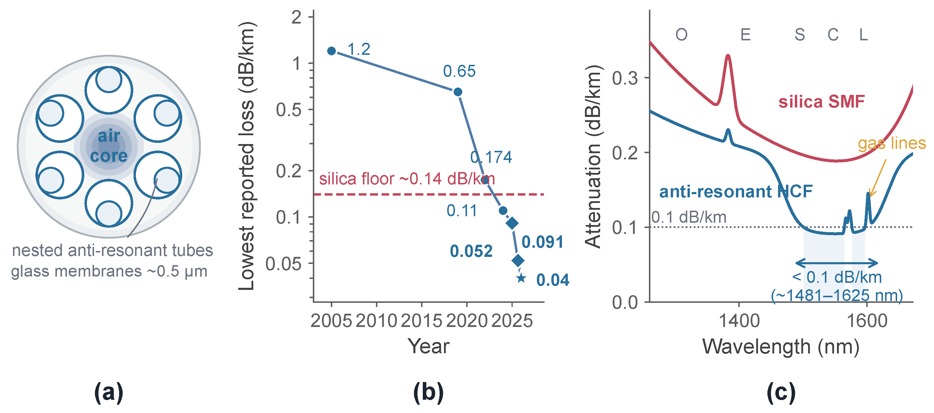
The loss trajectory follows this mechanistic shift (Figure 1b). Reported attenuation fell from 0.65 dB/km across the C and L bands in 2019 [6] to 0.174 dB/km in a double-nested design in 2022 [7], then to 0.091 dB/km at 1550 nm, measured over a 15-km fiber and below 0.1 dB/km across the 1481–1625 nm window, which was about 18 THz [8]. Most recently, two groups have pushed the record to the 0.05 dB/km level: an interstitial-tube-assisted DNANF with 0.052 dB/km over a 40-km span (and 0.076 dB/km over a record 83-km single-draw span) [9], and a support-tube design with 0.05 dB/km over 9.1 km [10]. These values sit well below silica’s ∼0.14 dB/km floor, and the low-loss band is markedly wider. The same mechanistic picture indicates where further headroom may lie: surface-scattering loss falls approximately as the inverse cube of core diameter and leakage falls faster still, so enlarging the core lowers both, while microbending sets a countervailing penalty—hence an optimum core size for each wavelength. Modeling on this basis places an optimized DNANF near 0.04 dB/km and, speculatively, an ultimate limit near 0.02 dB/km [5]; the newest measured results already approach the former. These records nonetheless warrant caution: the lowest values are reported for individual fibers and selected spans, different methods (cutback versus reflectometry) can disagree by tens of percent at these levels, and the broad-band figures are quoted with the gas-absorption features discussed later [8]. Batch statistics make the same point from the manufacturing side: across 733 km of drawn support-tube fiber the average attenuation was 0.147 dB/km [10]—the record and the production mean remain different numbers. The substantive claim is not that any single figure is final, but that the floor which organized silica-era design no longer self-evidently applies.
Three further properties follow from air guidance and matter as much as loss. First, the group index is close to unity rather than ∼1.47, so one-way delay is about a third lower, falling from ∼4.9 to ∼3.3 μs per kilometer [11]. This is a property of the medium, not a parameter to be iterated, and is essentially unique to air guidance. Second, because well over 99% of the power travels in air, the effective Kerr nonlinearity—which scales with the overlap of the optical field with glass—is several orders of magnitude smaller than in silica; reported nonlinear coefficients are of order 5 × 10 4 W−1 km−1 against ∼1.3 W−1 km−1 for SMF, and coherent transmission has been shown to be effectively nonlinearity-free even at watt-level powers [12,13,14]. Third, chromatic dispersion (CD) in the guidance window is low and relatively flat, of order 3 ps/(nm·km)—this is several times below standard fiber [8,13], although certain G.65X variants exhibit comparably low dispersion. Each of these reshapes a different part of the design stack, as the following sections detail.
These differences arrive as latency, energy per bit and physical-layer scaling become first-order constraints again—pushed by artificial intelligence (AI) training traffic, distributed data center architectures and dense interconnect. Industrial momentum has followed, including field and cabling trials and reports of deployments at the scale of thousands of kilometers by hyperscale operators [15,16,17,18]. What remains underdeveloped is a systems-level account of which silica-era choices are intrinsic to optical communication and which are artifacts of the medium. This paper takes up that question. We do not claim that HCF will replace silica or that its advantages are universal; we argue that its distinguishing properties are now large enough, and demonstrable enough, that treating the fiber as a faster drop-in pipe risks forfeiting most of its value.
Figure 1. Why hollow-core fiber has re-emerged. (a) Cross-section of a double-nested anti-resonant nodeless fiber (DNANF). (b) Lowest-reported HCF attenuation by year, with the silica record floor for reference (dashed) [3,6,7,8,9,10,19,20]. (c) Schematic attenuation spectra of silica SMF and anti-resonant HCF over O, E, S, C, L-bands (illustrative, not measured).
Photonics 13 00670 g001

2. Silica-Era Assumptions Under Reassessment

The rules of optical network design are not arbitrary, but many encode properties of silica rather than of communication itself. Separating the two is the central analytical task, and it is more useful than asking whether HCF is “better”: some conventions should survive unchanged, others invert, and the engineering value lies in knowing which, and by how much (Table 1). Reassessment is not reversal.

2.1. What Does Not Change: Medium-Independent Constraints

Several constraints are genuinely medium-independent. Information is carried on electromagnetic fields subject to the same quantum and thermal noise; amplified-spontaneous-emission (ASE) noise accumulates with distance and amplifier count; coherent detection, forward error correction (FEC) and the trade-off between spectral efficiency and reach all still hold; and a channel’s reach is still set by its accumulated generalized signal-to-noise ratio (GSNR). HCF does not repeal the Shannon limit. What it changes is the budget feeding the GSNR—how much loss, nonlinear penalty and delay each kilometer and each amplifier contribute.

2.2. Launch Power: From Kerr-Limited to Amplifier-Limited

The most consequential silica-specific assumption is that the optimum launch power is set by fiber nonlinearity. In a loaded WDM silica system, nonlinear interference acts as an additional noise source whose power grows roughly with the cube of per-channel launch power; meanwhile, the ASE contribution is approximately constant in absolute power, so its impact on SNR diminishes as signal power increases. This trade-off produces a nonlinear optimum, typically near 0–2 dBm per channel for 50 GHz channels—beyond which additional power degrades performance: the familiar “nonlinear Shannon” picture. Cutting the nonlinear coefficient by three orders of magnitude raises that optimum by tens of decibels, so it effectively ceases to bind [12]. Demonstrations now run boosters at 30–34.5 dBm and convert the resulting GSNR headroom into reach or spectral efficiency [21,22]. A subtler consequence is the decoupling of per-channel power. In silica, the nonlinear interference is intertwined across the comb—raising one channel’s launch power adds nonlinear penalty to its neighbors, so a channel cannot be tuned without degrading the rest. In HCF, the negligible nonlinearity removes this coupling, so each channel’s power becomes a near-independent control variable, which is precisely what makes per-channel transmitter-power optimization an effective way to equalize performance across a fully loaded link [23]. The constraint does not vanish; instead, it migrates to amplifier output power and efficiency, to optical damage and connectorization at the solid-core interfaces that bound an HCF span, to the gas-absorption and intermodal-interference effects, and to transceiver noise. Tellingly, network analyses already find that the best in-line amplifier output power is not the maximum available. From an electrical power consumption perspective, the optimum sits near 26 dBm, with diminishing or negative returns beyond roughly 32 dBm at a loss of 0.11 dB/km [24]. From a nonlinearity standpoint, the optimum shifts to around 37 dBm when considering the markedly reduced nonlinear coefficient of HCF, γ 5 × 10 4 W 1 km 1 , at a loss of 0.1 dB/km [25].
Table 1. Selected silica-era design assumptions and their status in an air-guided regime. The intent is to make dependencies explicit, not to claim that every convention should change. Entries are qualitative and indicate direction rather than settled conclusions.
Design AssumptionBasis in Silica SystemsStatus for Anti-Resonant HCF
Optimum launch power is set by Kerr nonlinearityNonlinear interference grows with power, creating a clear optimumReassess: nonlinearity is orders of magnitude lower; limits shift to amplifier power, interfaces and HCF-specific effects [12]
Usable spectrum is the silica window near 1550 nmLoss minimum and mature amplifiers sit in the C/L bandsReassess: low-loss guidance is broader and tunable, but amplifiers and components for new windows are immature [26,27]
Propagation delay is fixed by the mediumGroup index ∼1.47 is a material constantReassess: delay is ∼30% lower and becomes partly a design choice [11]
DSP must heavily manage chromatic dispersionStandard fiber has substantial accumulated dispersionReassess: dispersion is low and flatter in the guidance window [8,13]
Fiber is a near-ideal single-mode, low-reflection waveguideSMF is effectively single-mode with weak, well-characterized scatterReassess: effectively (not strictly) single-mode; IMI and very low backscatter change monitoring and transmission [5,28]
Reach is limited by accumulated SNR; Shannon limit appliesFundamental noise and capacity limitsRetain: unchanged by air guidance

2.3. Spectral Window, Delay, and Dispersion

The second assumption is spectral. Silica’s low-loss window near 1.55 μm is the crossover of Rayleigh scattering (falling as λ 4 ) and infrared absorption (rising with wavelength)—a property of the glass, and the reason the amplifier and component ecosystem clusters in the C and L bands. In anti-resonant HCF, the window is set instead by membrane thickness through the anti-resonance condition, decoupling it from material absorption; low loss has been measured across ∼18 THz and can in principle be placed from ∼1 μm to beyond 2 μm, with dual-band designs already demonstrated [8,26,27]. Whether this freedom is usable depends entirely on whether amplifiers and components exist for the chosen band—which today, outside the silica window, they largely do not. The third assumption, that propagation delay is fixed by the medium, gives way once n g 1 : delay becomes partly an engineering choice and, in a heterogeneous network, a per-path one. The fourth, that DSP must devote substantial resources to chromatic-dispersion compensation, weakens because the equalizer length scales with accumulated dispersion, which is several times lower and flatter here; the net receiver-DSP saving is real but bounded by the carrier-recovery, adaptive-equalization and FEC blocks that dominate complexity [8,13,29].

2.4. Assumptions That Are Incomplete Rather than Wrong

Finally, some assumptions are incomplete rather than wrong. Silica SMF is treated as a near-ideal, weakly scattering, single-mode, low-reflection waveguide. HCF is better described as effectively single-mode: higher-order modes exist but are differentially attenuated, and their residual coupling produces intermodal interference (IMI)—a coherent, multipath impairment with differential group delays of order nanoseconds per kilometer and no close analog in mature SMF links [5,30]. Backscatter is roughly 40 dB below that of SMF, which suppresses the coherent crosstalk that otherwise limits single-fiber bidirectional transmission, but simultaneously weakens the Rayleigh signal on which reflectometry depends [28]. Although bidirectional transmission has been demonstrated in laboratory settings, the larger reflections at SMF–HCF interfaces may render multipath interference (MPI) a practical limitation in field deployments, an issue that remains insufficiently studied. And because the core is hollow, trace CO2 and water vapor imprint narrow absorption lines on an otherwise flat spectrum [31,32]. The nearest silica counterpart is the OH “water peak”—overtone and combination absorption bands of hydroxyl incorporated during manufacture, most prominently near 1383 nm and its neighbors [33]—but the analogy is only partial: the OH bands are spectrally broad, fixed by the glass chemistry, and have been essentially eliminated from modern low-water-peak fibers, whereas the HCF gas lines are narrow (gigahertz-scale), scale with fill conditions and length, and can in principle be managed by controlling the gas content of the core rather than the glass. Air guidance thus redistributes both advantages and impairments; a framework inherited wholesale from silica will neither exploit the former nor anticipate the latter.

2.5. Why the Shifts Cross Layers

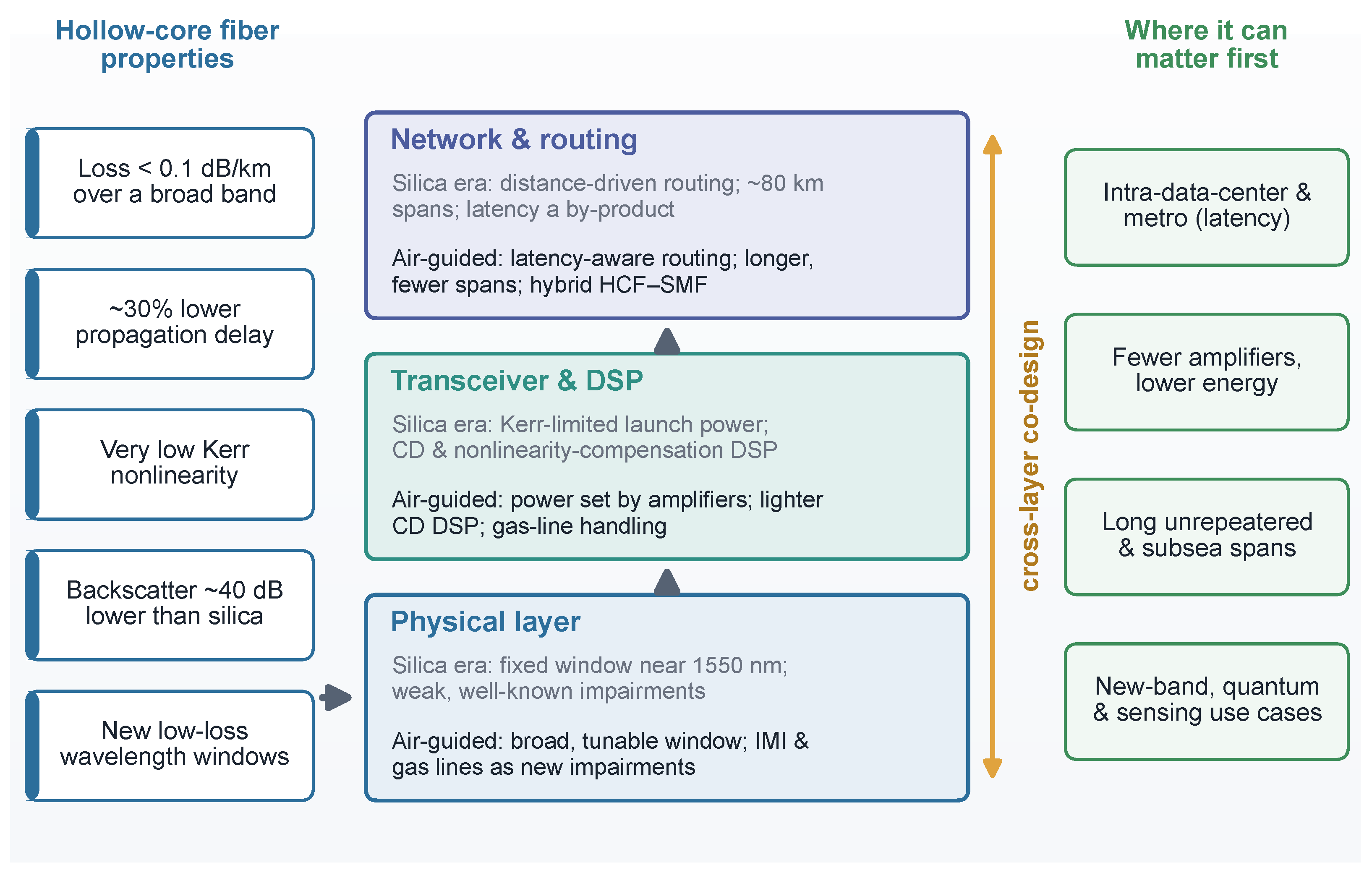
These shifts also refuse to stay within one layer, which is why piecemeal adoption tends to disappoint. A fiber-level change—lower nonlinearity, lower delay, a new gas-line impairment—yields value only if the transceiver, DSP and network layers are adjusted to exploit or absorb it: high launch power is wasted without amplifiers and interfaces that tolerate it; a broad low-loss band is inert without matching amplification; lower latency is invisible to a routing layer that does not treat delay as a variable. Figure 2 makes this coupling explicit, tracing how the distinguishing properties of HCF propagate from physical-layer design through transceiver and DSP choices to network and routing policy. This cross-layer view—not any single record metric—is the throughline of the two sections that follow.

3. Physical-Layer and Transceiver Implications

3.1. Launch Power, Modulation, and DSP

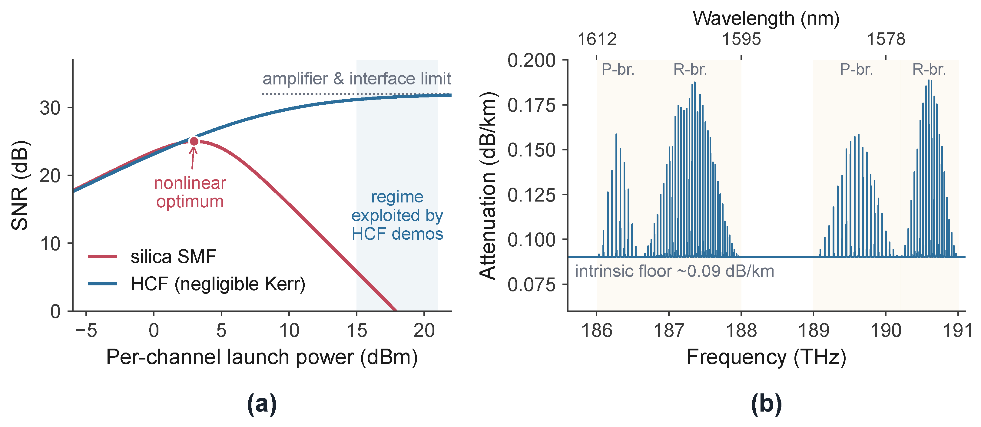
The lifted nonlinear ceiling reshapes the joint choice of launch power, modulation format and reach (Figure 3a). With nonlinear interference suppressed, the SNR-versus-power curve loses the peak that defines silica operation over the accessible power range, and the additional headroom has been spent in two ways. One is spectral efficiency: probabilistically shaped 64- and 256-QAM, supported by ring-wise neural-network equalization, has carried an aggregate ∼0.55 Pb/s across the S, C and L bands on a single fiber [34]. The other is reach at high power: boosted hybrid and unrepeated spans of hundreds of kilometers [21,22]. The lesson is not that more power is always better. The optimum migrates to amplifier saturation, efficiency and interface damage, and at network scale the economically optimal in-line power can sit well below the maximum—near 26 dBm in one transparent-network study, with no benefit, and eventually harm, beyond ∼32 dBm [24,35]. On DSP, the chromatic-dispersion equalizer is the one block whose length scales directly with accumulated dispersion; at ∼3 ps/(nm·km) it shrinks by roughly the dispersion ratio relative to standard fiber. But carrier recovery, adaptive equalization and FEC are unchanged, and—as the next paragraphs show—IMI and gas lines can add equalizer taps, so the net receiver-DSP complexity of an HCF link is not obviously lower and should be measured end-to-end rather than assumed. A further limit sits in the transceiver itself. Air guidance can supply ample link GSNR, but the back-to-back signal-to-noise ratio of the transponder—set by digital-to-analog and analog-to-digital converter (DAC/ADC) resolution, driver and modulator noise, and component bandwidth—degrades as the symbol rate rises, because the same impairments are spread over a wider band and the effective number of bits falls at high frequencies. At high baud, the transceiver noise floor, not the fiber, can cap the achievable SNR, so the headroom HCF opens at the link level need not translate into higher-order formats at arbitrarily increased baud. The practical operating point is therefore a joint optimization of baud rate, modulation order and reach against the transceiver noise floor, rather than a link-SNR calculation alone [29,36].
Figure 3. Physical-layer trade-offs under air guidance. (a) SNR versus per-channel launch power for silica SMF and HCF [12] (illustrative, not measured). (b) Modeled CO2 absorption comb in the L band, showing the P- and R-branches of two CO2 rotational–vibrational bands; loss per unit length at a 0.10 dB/km R-branch peak and 1 GHz linewidth [31,37,38] (illustrative, not measured).
Photonics 13 00670 g003

3.2. Bend Sensitivity, Mode, and Polarization Control

Several properties are reshaped rather than removed, and they trade against one another. Lower loss favors a larger air core, because both leakage and surface-scattering loss fall with core size; but microbending loss rises with core size, and so does bend sensitivity. The same core enlargement that modeling associates with pushing loss toward 0.03–0.02 dB/km also raises the radius at which bending becomes lossy, so that loss, bandwidth and bend tolerance cannot be maximized independently—they define a multi-objective optimum that depends on the deployment (tight data center routing versus long, gently bent spans) [5,8]. Mode control is likewise a design target, not a given: guidance is effectively, not strictly, single-mode, so a fiber must be engineered to differentially attenuate higher-order modes (often quantified by a higher-order-mode extinction ratio), and this competes with loss and bandwidth objectives, while bend- and splice-induced coupling can still dominate the IMI a deployed link actually sees [20,30]. Polarization behavior also differs: recent anti-resonant fibers report low polarization-mode dispersion (∼0.1 ps/ km ), unlike early bandgap fibers, but the phase and polarization dynamics of deployed cable—relevant to coherent receivers and to sensing—are only beginning to be characterized in the field [8,13,39].

3.3. Intermodal Interference: The Impairment That Replaces Nonlinearity

Reduced nonlinearity does not leave a clean channel; it exposes a different limit. Residual coupling to higher-order modes produces IMI, a coherent multipath effect that appears in the channel’s impulse response as a delayed plateau trailing the fundamental mode, with differential group delays of order 4–5 ns/km [30]. Reported IMI in recent low-loss fibers spans roughly 50 to below 70 dB/km [20,22], and modeling indicates that levels near 60 dB/km are needed for the impact on long-distance transmission to become negligible [25]—a threshold met in a fiber with an estimated IMI of 68.8 dB/km that enabled 6660 km transmission [22]. Two features make IMI strategically different from Kerr noise. First, it does not improve by lowering power; it is fixed by fiber and splice quality. Second, it accumulates with the worst segment, so a single non-uniform span or poor splice can set the IMI of an entire link, placing a premium on manufacturing uniformity and splice control [20]. Mitigations therefore act on the fiber (stronger higher-order-mode suppression) and on the DSP: digital subcarrier multiplexing narrows each subcarrier, which has been claimed to improve resilience to the frequency-selective fading that IMI produces, extending reach at comparable complexity [40].

3.4. Gas-Line Absorption: A New, Wavelength-Selective Limit

Because the core is hollow, residual CO2 and water vapor imprint their rotational–vibrational lines on the transmission spectrum as narrow notches—of order a gigahertz wide and, in the strongest lines, up to ∼0.5 dB/km deep—on an otherwise flat background (Figure 3b) [31,37,38]. Unlike the broad, manufacturing-controlled OH bands of silica [33], the loss here is channel-selective rather than band-wide, and because it scales with length a notch that is negligible over a few kilometers can exceed 10 dB over hundreds, removing specific channels rather than degrading all of them uniformly. Mitigations form a layered toolkit with quantified trade-offs. Fiber- and process-level methods reduce gas content or seal the core under positive pressure. At the transmitter, spectral pre-emphasis has extended reach from 150 to ∼300 km at a 1 dB penalty in one study, and frequency-domain spectral pre-equalization has recovered a 10 dB notch using three equalizer taps—about 5.5 dB better than a 383-tap adaptive equalizer [31,32]. Per-channel transmitter-power optimization has equalized performance across a fully loaded 32 × 800 Gb/s C-band link over 442 km, holding every channel above a 1.5 dB Q-margin [23]; adaptive baud-rate and subcarrier allocation that step signal energy around the lines have been used out to 6660 km [22]; and efficient in-field measurement can estimate the resulting penalty for deployment planning [37]. None removes the effect entirely—each trades against usable bandwidth or transmitter complexity—and the right combination is length- and band-specific [41].

3.5. Wavelength Windows and the Component Ecosystem

If the low-loss window is no longer tied to silica, new operating bands become conceivable: dual-band anti-resonant fibers with low loss at both ∼1 μm and ∼1.55 μm have been demonstrated, and fully integrated 1064 nm transmitters built explicitly to exploit such windows [27,42]. Realizing them depends on a component ecosystem that does not yet match C-band maturity—most pressingly, amplification for new or wider bands, and low-loss, low-reflection interfaces. The interface problem is concrete: the lowest-loss HCFs have mode-field diameters (MFDs) roughly twice that of SMF, and the air–glass boundary presents a ∼3.5% Fresnel reflection (about 0.155 dB) that, left untreated, both wastes power and seeds multipath echoes [43,44]. Progress is real but recent: homogeneous HCF–HCF splices average ∼0.05 dB with field-deployable automated alignment in under 100 s at full yield across repeated trials, and HCF–SMF coupling below 0.2 dB with back-reflection under 60 dB has been reached with mode-field adapters or lensed interfaces [43,44,45,46]. On the manufacturing side, in-line interferometric measurement with closed-loop pressure control has held capillary dimensions to about ±1% over a 20-km draw, a prerequisite for the uniformity that IMI demands [47]. These interface and yield economics, more than fiber loss, gate cost and reliability, and are likely to determine where HCF is adopted first.

3.6. Monitoring and Sensing

The ∼40 dB lower backscatter is doubly consequential [28]. It suppresses the coherent crosstalk that limits same-fiber bidirectional transmission, which several demonstrations exploit [48,49]; but it blinds the optical time-domain reflectometry (OTDR) [50,51] that operators rely on for fault location and live diagnostics. Because the HCF itself has negligible nonlinearity, longitudinal power-profile estimation must instead lean on the short solid-core jumpers embedded at amplifier sites, which still provide a usable nonlinear signature [30,52]. Pilot-tone-based monitoring, by contrast, becomes cleaner. Here a low-frequency, small-amplitude tone is superimposed on each data channel; in silica its accuracy is eroded by stimulated-Raman-scattering tone transfer between channels and by chromatic-dispersion-induced tone fading—two effects that push the optimal tone frequency in opposite directions and force a compromise. Air guidance removes the former through its negligible nonlinearity and suppresses the latter through its low dispersion, so the tone can be recovered without that trade-off [53]. Sensing inverts the usual hierarchy: the same low backscatter and roughly order-of-magnitude lower thermal sensitivity make HCF a poor distributed temperature sensor, although distributed sensing in unmodified NANF and in deployed field cables has already been demonstrated [39,54]. The general point is that HCF does not simply improve on silica’s auxiliary functions—it changes them, and the monitoring and sensing stack must be redesigned accordingly.
Table 2 summarizes the key physical-layer and transceiver findings of this section.
Table 2. Key physical-layer and transceiver findings (Section 3). Representative quantitative results from recent literature; all are laboratory or early-trial values.
TopicKey FindingRepresentative Results
Launch powerKerr optimum ceases to bind; limits migrate to amplifiers, interfaces and transceiver noiseBoosters at 30–34.5 dBm; network-optimal in-line power ∼26 dBm [21,24]
Modulation and DSPCD equalizer shrinks by the dispersion ratio, but IMI/gas-line handling can add taps; transceiver back-to-back SNR caps high-baud formats∼0.55 Pb/s over S+C+L bands with shaped 64/256-QAM [29,34,36]
Intermodal interferenceReplaces nonlinearity as the reach-limiting impairment; set by the worst segment, not by power 50 to < 70 dB/km reported; 60 dB/km needed for negligible long-distance impact [20,22,25]
Gas-line absorptionNarrow, length-scaling notches remove specific channels; layered mitigation toolkitPre-emphasis: 150 → 300 km at 1 dB penalty; 3-tap pre-equalization recovers a 10 dB notch [31,32]
Interfaces and splicingInterface economics, more than loss, gate adoptionHCF–HCF splices ∼0.05 dB; HCF–SMF coupling <0.2 dB with < 60 dB back-reflection [43,45,46]
Monitoring and sensingOTDR blinded; pilot tones cleaner; sensing hierarchy invertedBackscatter ∼40 dB below SMF [28,53]

4. Network Architecture and Routing

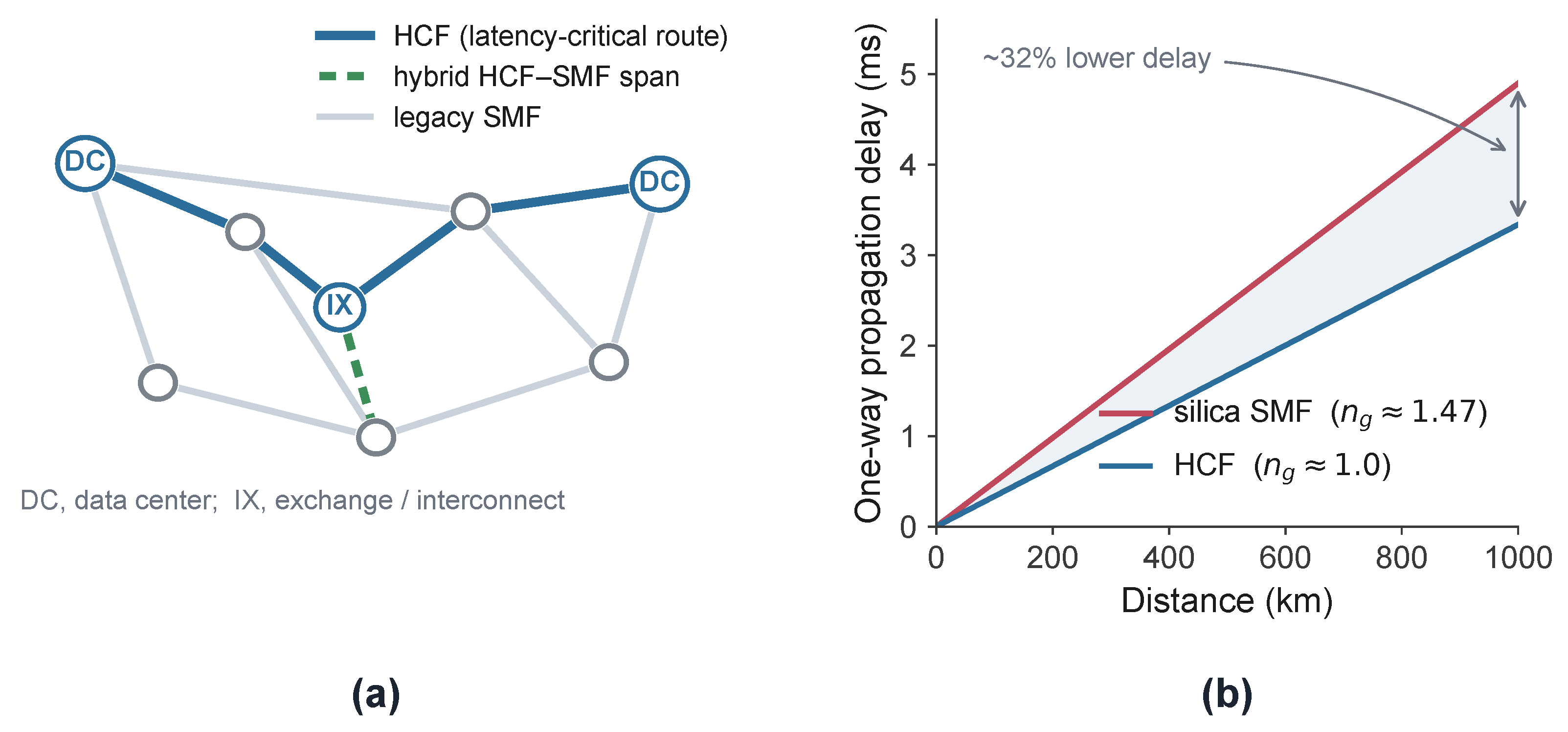
The properties that reshape the physical layer also have a bearing on where HCF is deployed and how networks are planned. Three regimes stand out as early candidates for decisive advantage, and one cross-cutting idea—treating latency as a design variable—runs through them (Figure 4).

4.1. Where HCF May Help First

The clearest near-term case is the latency-bounded, distance-limited link. Data center interconnect and metro routes turn roughly 30% lower propagation delay directly into application value—tighter clock synchronization, lower round-trip times for distributed storage and consensus, and higher goodput for the latency-gated collective operations that increasingly dominate artificial intelligence training—while their short reach keeps the amplifier and interface count modest [11,16]. Bidirectional, full-band transmission over field-deployable HCF cable using commercial coherent pluggables has been shown, making this regime concrete rather than hypothetical [48,49]. A second case is the amplifier- and energy-constrained route. Below 0.1 dB/km, a span of fixed length incurs roughly half the loss of an SMF span, or equivalently the span can be doubled in length for the same loss, halving the number of in-line amplifier sites; transparent-network analyses translate this into amplifier power savings of order tens of percent per Tb/s and into capacity gains, with one study reporting up to a doubling of maximum network capacity and a ∼35% reduction in energy per transported bit when long, low-loss spans are combined with an amplifier power optimum near 26 dBm [16,24]. A third, more forward-looking case is the long unrepeated or sparsely repeated span. Hybrid HCF–SMF spans exceeding 200 km have delivered >800 Gb/s achievable information rate over 1113 km, and a sparsely repeated transoceanic experiment reached 6660 km using 266-km spans with fewer than 30 repeaters—against the ∼100 of a conventional system— enabled jointly by low IMI ( 68.8 dB/km), high-power boosting and adaptive baud-rate management around the gas lines [21,22]. These remain laboratory or trial results, frequently in recirculating loops, and their translation to fielded systems is not yet established.

4.2. Fiber Connections Within Data Centers

A fourth candidate sits inside the data center itself, and deserves separate mention because its economics differ from all of the above. In large AI training clusters, the synchronization and collective-communication phases are latency-gated: measurements on production systems report model-FLOPs utilization near 55% at the 10,000-GPU scale even after aggressive communication–computation overlap, so a substantial fraction of accelerator cycles is already lost to waiting on the network [55,56]. Intra-facility links are short (tens of meters to ∼2 km), so fiber loss is immaterial and no in-line amplification is involved; what HCF changes is the per-meter delay, cutting propagation latency by ∼30% on every hop of every collective operation [11]. Because these links are short, patch-cord-like and numerous, they also sidestep several of HCF’s open long-haul questions (accumulated IMI, gas-line growth with length) while stressing others—bend radius in dense routing, connectorization cost and density—which ties this use case directly to the bend-tolerance and interface trade-offs of Section 3.2 and Section 3.5. Early bidirectional deployments over tens of kilometers between data center halls point the same way [16,49]. Whether replacing copper and MMF/SMF cabling inside facilities pays off will depend on connector economics at scale, but the latency arithmetic—nanoseconds per meter saved, multiplied across millions of collective operations—makes intra- and inter-hall cabling a natural early market alongside data center interconnect (DCI).

4.3. The Breadth of Demonstrations

The breadth of demonstrations is itself the signal. Across the network they now span access (bidirectional coherent passive optical networking over anti-resonant HCF at 200/50 Gb/s down/up), the data center and metro tier (wavelength-reconfigurable optical switching at multi-petabit aggregate scale), and the high-capacity core (∼0.55 Pb/s on one fiber, and real-time 2 Tb/s-class transponders over a 120-km HCF span with latency comparable to 80 km of SMF) [34,57,58]. Taken together—and with the caveat that most are trials—these indicate that raw capacity is not the binding constraint. The open questions concern cost, interfaces, impairments and day-to-day operation, which shifts the center of gravity of the problem from the fiber to the system and the network.

4.4. Hybrid Silica–HCF Networks

For the foreseeable future networks will be heterogeneous [59,60], with HCF introduced selectively alongside an installed silica base, so the design question is which links or spans to convert under a fixed budget. The quantitative answers are encouraging but assumption-dependent. GSNR-based studies on realistic carrier topologies report HCF advantages of up to ∼8 dB and carried-traffic gains of order ten percent over an all-SMF baseline, bracketed by the assumed loss, splice quality and amplifier configuration [13]. Time-domain modeling of multi-span systems finds that 25–50% of the HCF can be removed in favor of SMF with little performance loss in metro and unrepeated regimes, because much of HCF’s benefit comes from loss and high-power tolerance that a hybrid span can capture with less fiber [14,21]. And integer-programming placement studies show feasible-path counts for 800 Gb/s rising by about 36% when only 10% of spans are HCF and by up to 100% at a 20% budget, with 85% of feasible paths reachable when 25–55% of spans are converted [61]. The consistent message—that a minority of well-chosen HCF can capture most of the benefit—reframes deployment as a budgeted optimization rather than wholesale replacement, but the specific fractions are sensitive to the input assumptions and should guide experiments rather than substitute for them.

4.5. Latency as a First-Class Routing Variable

Conventional routing and wavelength assignment optimize for cost, capacity and reach, treating propagation latency as a by-product of the chosen path. This is reasonable in an all-silica network, where every fiber kilometer carries the same group index and therefore the same delay. Heterogeneity breaks the assumption: two paths of equal physical length can differ in latency according to how much of each traverses air-guided fiber (Figure 4b), so delay becomes a controllable, per-path quantity. This invites treating latency as an explicit routing metric or constraint alongside capacity and cost—most valuably for traffic with hard delay bounds: the synchronization and collective-communication phases of distributed AI training, where tail latency can gate cluster throughput, financial messaging, industrial control, and distributed consensus [56]. Delay-constrained routing is itself well studied, but it has not had to contend with a physical layer in which the delay per kilometer varies by medium, nor with the coupled decision of where to place a limited budget of low-latency fiber. Network studies that begin from latency or energy budgets already hint at the payoff: selectively upgrading under a fifth of links can cut edge data center consolidation cost by tens of percent under latency bounds, and similar selective placement reduces the resources needed for quantum-key distribution [16,61]. We advance this as a hypothesis to be tested, not a settled result: the open question is whether planning tools and control-plane abstractions that treat fiber type, latency and energy as joint variables can realize, on real traffic, the advantage the physical layer now makes available.
Table 3 collects the network-level evidence discussed in this section.

5. Roadmap and Open Questions

If HCF is to be more than a faster pipe, the community needs evidence on where air guidance changes the right engineering answer, not merely where it improves a fiber metric. We see six concrete priorities, as summarized in Table 4.

5.1. Standardized, Independent Characterization

The headline loss, IMI and gas-absorption figures are reported for individual fibers and lengths, sometimes with key quantities (the lowest losses, the wide-band projections) derived from modeling rather than measured [5,8]. The field needs agreed methods—loss measured over tens of kilometers rather than extrapolated, IMI and differential mode attenuation, backscatter, and gas-line spectra under controlled fill—together with independent cross-checks and round robin comparisons. Standardization activity in this direction has begun and deserves support [17]; without it, system designers cannot use the numbers with confidence.

5.2. Standardization of Fiber Dimensions and Interfaces

A related but distinct gap concerns the physical parameters of the fiber itself. Unlike silica SMF, for which ITU-T G.652 and its siblings fix the cladding diameter and MFD and geometry tolerances that make any two vendors’ fibers spliceable, no equivalent recommendation yet exists for HCF: core and microstructure designs differ between suppliers, reported cladding diameters vary (roughly 125–250 μm depending on design), and MFDs of low-loss designs (∼17–24 μm) are roughly twice that of SMF [35,43]. This matters most for fusion splicing and connectorization: splice recipes, mode-field adapters and test procedures are all vendor-specific today, so multi-vendor deployment is not a drop-in exercise and interoperability requires coordinated qualification. In our view this lack of dimensional and interface standards is itself a first-order brake on adoption—arguably ahead of any remaining fiber-performance gap. Standardization work has begun—ITU-T Study Group 15 is developing technical material on HCF, with parallel activity in IEC SC86A and CCSA [17,62]—and converging early on cladding diameter, MFD ranges and splice-loss test methods would compound the value of every other item on this roadmap.

5.3. System Studies That Price the New Impairments

The benefits of low nonlinearity, low delay and low dispersion must be weighed against IMI, gas-line absorption and interface loss in fully loaded, multi-span links representative of deployment—not single-channel or recirculating-loop experiments, which can flatter both the benefits and the impairments. The most useful studies will report the net receiver-DSP and amplifier complexity of an HCF system, so that the equalizer taps saved on dispersion and the taps spent on IMI and gas lines are counted together, and so that high-power operation is costed against amplifier efficiency and reliability [24,40,52]. A parallel question is whether the modulation format itself can be chosen to minimize the new impairments rather than merely tolerate them: digital subcarrier multiplexing, OFDM and other multicarrier or adaptively shaped waveforms can narrow and steer subcarriers around gas lines and spread energy to resist the frequency-selective fading IMI produces. A systematic comparison of these formats—on the joint axes of IMI and gas-line resilience, reach and DSP cost—would help identify which waveform is best matched to an air-guided channel [38,40].

5.4. The Interface and Component Ecosystem

Field-grade, low-loss, low-reflection HCF–SMF interfaces, fast and reliable splicing, manufacturing uniformity sufficient to keep link-level IMI below threshold, and amplification matched to wider or new bands are prerequisites for most use cases—and, as argued above, their economics may set adoption timing more than fiber loss does [27,43,45,47]. New-band amplification, in particular, is the gating technology for exploiting HCF’s broader low-loss window at all; candidate gain media exist—ytterbium near 1 μm, bismuth in the O, E and S bands, thulium and holmium near 2 μm—but none are mature at telecom scale [8]. Two further unknowns belong on the same list: absolute cable cost, for which little public data exist while manufacturing scales up, and long-term reliability—aging of the thin membranes, gas or moisture ingress at cable breaks, and field repair—which remains essentially uncharacterized.

5.5. Cross-Layer Co-Design and Planning

The hybrid-deployment and latency-as-metric questions call for planning tools and control-plane abstractions that treat fiber type, latency and energy as joint optimization variables rather than post hoc attributes. The decisive evidence would be field-representative testbeds that route real delay-bounded traffic over mixed HCF–SMF paths and demonstrate, end to end, that latency-aware placement and routing deliver the predicted gains [14,16,61]. Several directions are actionable now. First, extend GSNR-based routing-and-wavelength-assignment engines so that fiber type, group delay and energy per bit are carried as first-class link weights, rather than attributes recovered after the path is fixed; on hybrid routes, this means making the engine explicitly fiber-transition-aware, modeling each SMF–HCF junction as its own element so that the interface loss and back-reflection it adds, the segment-by-segment change in dispersion, and the IMI and gas-line penalties that accrue only on the air-guided portions are all priced into the path metric—and so that a route is penalized for the number of transitions it incurs, not merely for the fraction of HCF it traverses. Second, frame selective deployment as a budgeted placement problem—ranking candidate spans by marginal benefit per unit cost (latency removed, amplifier sites saved, feasible high-rate paths gained) and converting greedily under explicit capital-expenditure and energy ceilings [61]. Third, agree on a control-plane data model that exposes fiber type, accumulated IMI and the per-channel gas-line map to the planner, so that the routing and optical layers act on a shared view of the link. Finally, because launch power, modulation format and route are coupled once the medium varies along a path, these should be optimized jointly rather than in sequence—and this joint optimization must treat the transceiver back-to-back SNR as a hard ceiling, since the GSNR headroom HCF opens at the link level is wasted on any route that is already transceiver-limited. The co-design response is to spend that headroom where the converters can use it: rather than chasing record symbol rates the DACs and ADCs cannot support, exploit HCF’s wide low-loss window for parallelism—many moderate-baud subcarriers across the band rather than a few ultra-high-baud carriers—combined with probabilistic constellation shaping and digital pre-distortion so that the planner directs GSNR headroom to the routes and formats where it actually converts to delivered capacity.

5.6. Beyond Transmission

Higher delivered power, lower loss and new wavelength windows also bear on adjacent functions—power-over-fiber beyond the fiber-fuse limit of silica, wider repeater spacing and memory-native wavelengths for quantum networking, and distributed sensing with behavior distinct from silica—where the early evidence is promising but largely model- or proof-of-concept-based [54,63,64]. Because these uses may favor different fiber designs and wavelengths, they could influence which variants the ecosystem ultimately standardizes on.

6. Concluding Remarks

The honest summary is that HCF stands at an inflection point but is not yet mature. Its distinguishing properties are real and, for the first time, demonstrable at system scale; its impairments are equally real and less familiar and most of the decisive evidence remains to be gathered in fully loaded, fielded systems. The constructive stance is neither uncritical enthusiasm nor dismissal as a niche medium, but a deliberate program of cross-layer co-design and independent measurement to locate, quantitatively, where air guidance changes the answer—and where it does not. Treated as a catalyst for re-examining inherited assumptions rather than as a drop-in replacement, HCF is most likely to yield an advantage that endures.

Author Contributions

Conceptualization, M.G.S. and Z.J.; methodology, M.G.S.; investigation, M.G.S. and Z.J.; writing—original draft preparation, M.G.S.; writing—review and editing, M.G.S. and Z.J.; visualization, M.G.S.; supervision, Z.J. All authors have read and agreed to the published version of the manuscript.

Funding

This research received no external funding.

Data Availability Statement

The datasets generated in this paper are available from the corresponding author on reasonable request.

Acknowledgments

The views and opinions expressed in this document belong solely to the authors and do not reflect Huawei’s official stance. Generative AI (GPT 5.4) was utilized to refine language and grammar.

Conflicts of Interest

At the time of the study, the authors were employed by the Ottawa Research Center, Huawei Technologies Canada. The authors declare that there are no conflicts of interest related to this work.

Abbreviations

The following abbreviations are used in this manuscript:
ADCAnalog-to-digital converter
AIArtificial intelligence
ASEAmplified spontaneous emission
CCSAChina Communications Standards Association
CDChromatic dispersion
DACDigital-to-analog converter
DCIData center interconnect
DNANFDouble-nested anti-resonant nodeless fiber
DSPDigital signal processing
FECForward error correction
GSNRGeneralized signal-to-noise ratio
HCFHollow-core fiber
IECInternational Electrotechnical Commission
IMIIntermodal interference
ITU-TInternational Telecommunication Union-Telecommunication Standardization Sector
MFDMode-field diameter
MMFMultimode fiber
MPIMultipath interference
NANFNested anti-resonant nodeless fiber
OFDMOrthogonal frequency-division multiplexing
OTDROptical time-domain reflectometry
PMDPolarization-mode dispersion
PONPassive optical network
QAMQuadrature amplitude modulation
SMFSingle-mode fiber
SNRSignal-to-noise ratio
WDMWavelength-division multiplexing

References

  1. Cregan, R.F.; Mangan, B.J.; Knight, J.C.; Birks, T.A.; Russell, P.S.J.; Roberts, P.J.; Allan, D.C. Single-Mode Photonic Band Gap Guidance of Light in Air. Science 1999, 285, 1537–1539. [Google Scholar] [CrossRef] [Scilit] [PubMed]
  2. Russell, P.S.J. Photonic Crystal Fibers. Science 2003, 299, 358–362. [Google Scholar] [CrossRef] [Scilit] [PubMed]
  3. Roberts, P.J.; Couny, F.; Sabert, H.; Mangan, B.J.; Williams, D.P.; Farr, L.; Mason, M.W.; Tomlinson, A.; Birks, T.A.; Knight, J.C.; et al. Ultimate low loss of hollow-core photonic crystal fibres. Opt. Express 2005, 13, 236–244. [Google Scholar] [CrossRef] [Scilit] [PubMed]
  4. Poletti, F. Nested antiresonant nodeless hollow core fiber. Opt. Express 2014, 22, 23807–23828. [Google Scholar] [CrossRef] [Scilit] [PubMed]
  5. Numkam Fokoua, E.; Mousavi, S.A.; Jasion, G.T.; Richardson, D.J.; Poletti, F. Loss in hollow-core optical fibers: Mechanisms, scaling rules, and limits. Adv. Opt. Photonics 2023, 15, 1–85. [Google Scholar] [CrossRef] [Scilit]
  6. Bradley, T.D.; Jasion, G.T.; Hayes, J.R.; Chen, Y.; Hooper, L.; Sakr, H.; Alonso, M.; Taranta, A.; Saljoghei, A.; Mulvad, H.C.; et al. Antiresonant Hollow Core Fibre with 0.65 dB/km Attenuation across the C and L Telecommunication Bands. In Proceedings of the 45th European Conference on Optical Communication (ECOC), Dublin, Ireland, 22–26 September 2019. [Google Scholar]
  7. Jasion, G.T.; Sakr, H.; Hayes, J.R.; Sandoghchi, S.R.; Hooper, L.; Fokoua, E.N.; Saljoghei, A.; Mulvad, H.C.; Alonso, M.; Taranta, A.; et al. 0.174 dB/km Hollow Core Double Nested Antiresonant Nodeless Fiber (DNANF). In Proceedings of the Optical Fiber Communication Conference (OFC), San Diego, CA, USA, 6–10 March 2022. [Google Scholar] [CrossRef] [Scilit]
  8. Petrovich, M.N.; Numkam Fokoua, E.; Chen, Y.; Sakr, H.; Adamu, A.I.; Hassan, R.; Wu, D.; Fatobene Ando, R.; Papadimopoulos, A.; Sandoghchi, S.R.; et al. Broadband optical fibre with an attenuation lower than 0.1 decibel per kilometre. Nat. Photonics 2025, 19, 1203–1208. [Google Scholar] [CrossRef] [Scilit] [PubMed]
  9. Gao, S.; Chen, H.; Sun, Y.; Xiong, Y.; Yang, Z.; Zhao, R.; Ding, W.; Wang, Y. 40 km, 0.052 dB/km and 83 km, 0.076 dB/km in Interstitial-Tube-Assisted Hollow-Core Fibre. In Proceedings of the 2025 European Conference on Optical Communications (ECOC), Copenhagen, Denmark, 28 September–2 October 2025. [Google Scholar] [CrossRef] [Scilit]
  10. Ding, Y.; Li, P.; Chen, G.; Chu, J.; Jia, A.; Zhang, L.; Luo, J. Support Tube Hollow-Core Fiber with 0.05 dB/km Attenuation. In Proceedings of the 2025 European Conference on Optical Communications (ECOC), Copenhagen, Denmark, 28 September–2 October 2025. [Google Scholar] [CrossRef] [Scilit]
  11. Poletti, F.; Wheeler, N.V.; Petrovich, M.N.; Baddela, N.; Numkam Fokoua, E.; Hayes, J.R.; Gray, D.R.; Li, Z.; Slavík, R.; Richardson, D.J. Towards high-capacity fibre-optic communications at the speed of light in vacuum. Nat. Photonics 2013, 7, 279–284. [Google Scholar] [CrossRef] [Scilit]
  12. Liu, Z.; Karanov, B.; Galdino, L.; Hayes, J.R.; Lavery, D.; Clark, K.; Shi, K.; Elson, D.J.; Thomsen, B.C.; Petrovich, M.N.; et al. Nonlinearity-Free Coherent Transmission in Hollow-Core Antiresonant Fiber. J. Light. Technol. 2019, 37, 909–916. [Google Scholar] [CrossRef] [Scilit]
  13. Correia, B.; Pedro, J. Hollow-Core Fiber Properties and System-Level Specifications for Next-Generation Optical Transport Networks. Photonics 2026, 13, 71. [Google Scholar] [CrossRef] [Scilit]
  14. Braga, L.S.; Renaudier, J.; Ghazisaeidi, A. Fiber Mixture Optimization of Future Hybrid HCF–SMF Multi-Span Transmission Systems. In Proceedings of the Optical Fiber Communication Conference (OFC), Los Angeles, CA, USA, 15–19 March 2026. [Google Scholar]
  15. Microsoft Corp. Microsoft Acquires Lumenisity, an Innovator in Hollow Core Fiber (HCF) Cable; Official Microsoft Blog; Microsoft Corp.: Redmond, WA, USA, 2022. [Google Scholar]
  16. Ibrahimi, M.; Sticca, G.S.; Musumeci, F.; Tornatore, M. Emerging Network-Wide Use Cases for Hollow Core Fibers (Invited). In Proceedings of the Optical Fiber Communication Conference (OFC), Los Angeles, CA, USA, 15–19 March 2026. [Google Scholar]
  17. Ge, D.; Wang, D.; Zuo, M.; Li, H.; Zhang, D. Real-Time High-Speed Transmission over Deployed AR-HCFs: Challenges, Enabling Technologies, and Future Perspectives. In Proceedings of the Optical Fiber Communication Conference (OFC), Los Angeles, CA, USA, 15–19 March 2026. [Google Scholar]
  18. Borzycki, K.; Osuch, T. Hollow-Core Optical Fibers for Telecommunications and Data Transmission. Appl. Sci. 2023, 13, 10699. [Google Scholar] [CrossRef] [Scilit]
  19. Chen, Y.; Petrovich, M.N.; Fokoua, E.N.; Adamu, A.I.; Hassan, M.R.A.; Sakr, H.; Slavík, R.; Gorajoobi, S.B.; Alonso, M.; Ando, R.F.; et al. Hollow Core DNANF Optical Fiber with <0.11 dB/km Loss. In Proceedings of the Optical Fiber Communication Conference (OFC), San Diego, CA, USA, 24–28 March 2024. [Google Scholar]
  20. Li, P.; Chen, G.; Jia, A.; Li, H.; Chu, J.; Liu, Y.; Zhang, L.; Zhang, L.; Luo, J. Low Intermodal Interference and Low Loss Hollow Core Fibers. In Proceedings of the Optical Fiber Communication Conference (OFC), Los Angeles, CA, USA, 15–19 March 2026. [Google Scholar]
  21. Mardoyan, H.; Ospina, R.S.; Carrero, C.C.; Ghazisaeidi, A.; Boddeda, R.; Li, P.; Zhang, L.; Luo, J.; Fu, C.; Hu, C.; et al. 222-km-long Hybrid Span Transmission Systems made of Support-Tube Hollow Core Fiber and Standard Single-Mode Fiber using a High-Power Doped-Fiber Amplifier. In Proceedings of the Optical Fiber Communication Conference (OFC), Los Angeles, CA, USA, 15–19 March 2026. [Google Scholar]
  22. Boddeda, R.; Castineiras Carrero, C.; Mardoyan, H.; Ghazisaeidi, A.; Li, P.; Li, S.; Zhang, L.; Luo, J.; Renaudier, J. Sparsely Repeated 21.7 Tb/s Net-Rate Transoceanic Transmission with 266-km Ultra-Long Spans Enabled by Low-IMI and Low-Loss Hollow Core Fiber. In Proceedings of the Optical Fiber Communication Conference (OFC), Los Angeles, CA, USA, 15–19 March 2026. [Google Scholar]
  23. Hong, Y.; Kamalian-Kopae, M.; Ali, A.; Gholizadeh, B.; Bawn, S.; Hooley, J.; Gorajoobi, S.B.; Wallace, C.; Gaudette, J.; Richardson, D.J.; et al. Transmitter Power Optimization for Uniform-Performance Multi-Span Hollow-Core Fiber Transmission. In Proceedings of the Optical Fiber Communication Conference (OFC), Los Angeles, CA, USA, 15–19 March 2026. [Google Scholar]
  24. Zami, T.; Rossi, N.; Lavigne, B. Optimal Output Power for C-band Optical Amplifiers in Transparent WDM Networks Based on Hollow Core Fiber. In Proceedings of the Optical Fiber Communication Conference (OFC), Los Angeles, CA, USA, 15–19 March 2026. [Google Scholar]
  25. Poggiolini, P.; Poletti, F. Opportunities and Challenges for Long-Distance Transmission in Hollow-Core Fibres. J. Light. Technol. 2022, 40, 1605–1616. [Google Scholar] [CrossRef] [Scilit]
  26. Sakr, H.; Bradley, T.D.; Jasion, G.T.; Numkam Fokoua, E.; Sandoghchi, S.R.; Davidson, I.A.; Taranta, A.; Guerra, G.; Shere, W.; Chen, Y.; et al. Hollow core optical fibres with comparable attenuation to silica fibres between 600 and 1100 nm. Nat. Commun. 2020, 11, 6030. [Google Scholar] [CrossRef] [Scilit] [PubMed]
  27. Mahdiraji, G.A.; Mousavi, S.M.A.; Wu, D.; Varghese, T.; Baddela, N.K.; Hassan, M.R.B.A.; Kakaei, Z.; Adamu, A.I.; Zhai, Z.; Wisniowski, K.; et al. First Dual-Band Hybrid-Window Antiresonant HCF with 0.13 dB/km Loss at 1 μm and 0.11 dB/km at 1.55 μm. In Proceedings of the Optical Fiber Communication Conference (OFC), Los Angeles, CA, USA, 15–19 March 2026. [Google Scholar]
  28. Nakamura, A.; Hayakawa, J.; Iida, H.; Toge, K. Backscattering Characterization in Hollow-Core Fibers: Isolating Air-Molecule and Surface-Scattering Origins via Direct and Coherent OTDR Techniques. In Proceedings of the Optical Fiber Communication Conference (OFC), Los Angeles, CA, USA, 15–19 March 2026. [Google Scholar]
  29. Saber, M.G.; Jiang, Z. Practical Limits of Higher-Order QAM in Hollow-Core Fiber Systems. arXiv 2026, arXiv:2606.23527. [Google Scholar] [CrossRef] [Scilit]
  30. Fontaine, N.K.; Grilanda, S.; Ryf, R.; Dallachiesa, L.; Neilson, D.T.; Chen, H.; Mazur, M.; Li, P.; Zhang, L.; Luo, J.; et al. Characterization of Multi-Path Interference of 10-km Hollow Core Fiber using Swept-Wavelength Interferometry. In Proceedings of the Optical Fiber Communication Conference (OFC), Los Angeles, CA, USA, 15–19 March 2026. [Google Scholar]
  31. Li, C.; Liu, H.; Qiu, Q.; Wang, Z.; Jiang, H.; Chen, Y.; Wang, Y.; Chen, H.; Yan, B.; Shi, H.; et al. DSP Optimization for CO2 Absorption Impact in Hollow Core Fiber Coherent Optical Transmission Systems. In Proceedings of the Optical Fiber Communication Conference (OFC), Los Angeles, CA, USA, 15–19 March 2026. [Google Scholar]
  32. Sillekens, E.; Sohanpal, R. Gas-Line Absorption Mitigation in Hollow-Core Fibre using Spectral Pre-Equalisation. In Proceedings of the Optical Fiber Communication Conference (OFC), Los Angeles, CA, USA, 15–19 March 2026. [Google Scholar]
  33. Humbach, O.; Fabian, H.; Grzesik, U.; Haken, U.; Heitmann, W. Analysis of OH absorption bands in synthetic silica. J. Non-Cryst. Solids 1996, 203, 19–26. [Google Scholar] [CrossRef] [Scilit]
  34. Li, X.; Zhang, T.; Mi, S.; Zhang, X.; Ji, H.; Chen, H.; Lu, Y.; Li, C.; Luo, M.; Sun, P.; et al. Beyond 550 Tb/s S+C+L-band Bidirectional Transmission over 10.9-km Anti-Resonant Hollow-Core Fiber. In Proceedings of the Optical Fiber Communication Conference (OFC), Los Angeles, CA, USA, 15–19 March 2026. [Google Scholar]
  35. Saber, M.G.; Jiang, Z. Hollow-Core Fiber in Direct-Detection Optical Networks: Technology Readiness, Deployment Drivers, and Adoption Outlook. arXiv 2026, arXiv:2606.23511. [Google Scholar] [CrossRef] [Scilit]
  36. Klaus, W.; Winzer, P.J. Hollow-core fiber capacities with receiver noise limitations. In Proceedings of the Optical Fiber Communication Conference (OFC), San Diego, CA, USA, 6–10 March 2022. [Google Scholar] [CrossRef] [Scilit]
  37. He, Y.; Chen, S.; Dou, L.; Zhai, Z.; Zhang, H.; Su, Y.; Lau, A.P.T. Accelerating Hollow-Core Fiber Deployment: An Efficient One-Shot Field Measurement Technique to Characterize CO2 Absorption-Induced OSNR Penalty. In Proceedings of the Optical Fiber Communication Conference (OFC), Los Angeles, CA, USA, 15–19 March 2026. [Google Scholar]
  38. Wang, X.; Li, Z.; Feng, L.; Li, P.; Lv, K.; Sheng, X.; Liu, Y.; Gao, R.; Xin, X.; Zhang, L.; et al. Simulation investigation of CO2 absorption-induced performance degradation in hollow-core fiber transmission systems and spectrum-optimized digital sub-carrier multiplexing design for circumvention. Opt. Lett. 2025, 50, 7171–7174. [Google Scholar] [CrossRef] [Scilit] [PubMed]
  39. Fang, J.; Huang, M.F.; Kotrla, S.; Mundt, J.A.; Wang, T.; Aono, Y. Field Study on Phase and Polarization Dynamics of Deployed Anti-Resonant Hollow Core Fiber Cable for Vibration Sensing. In Proceedings of the Optical Fiber Communication Conference (OFC), Los Angeles, CA, USA, 15–19 March 2026. [Google Scholar]
  40. Ospina, R.S.; Carrero, C.C.; Mardoyan, H.; Ghazisaeidi, A.; Boddeda, R.; Li, P.; Zhang, L.; Luo, J.; Renaudier, J. Leveraging Digital Subcarrier Multiplexing for Long-Haul Transmission over HCFs in the Presence of IMI. In Proceedings of the Optical Fiber Communication Conference (OFC), Los Angeles, CA, USA, 15–19 March 2026. [Google Scholar]
  41. Saber, M.G.; Jiang, Z. CO2-Limited Hollow-Core Fiber Links: A Capacity-Map Guide to Pre-Emphasis and Spectral Avoidance. Photonics 2026, 13, 559. [Google Scholar] [CrossRef] [Scilit]
  42. Shen, B.; Bian, K.; Asawa, K.; Kudelin, I.; Morin, T.; Song, B.; Shen, Y.; Guo, J.; Peters, J.; Nguyen, C.; et al. Fully Integrated 1064 nm Transmitters with Widely Tunable GaAs Lasers and >100-GHz Thin-Film LiNbO3 Modulators. In Proceedings of the Optical Fiber Communication Conference (OFC), Los Angeles, CA, USA, 15–19 March 2026. [Google Scholar]
  43. Slavík, R.; Komanec, M.; Poletti, F. Making the Hollow Core Fibers Compatible with Current Fiber Infrastructure. In Proceedings of the Optical Fiber Communication Conference (OFC), Los Angeles, CA, USA, 15–19 March 2026. [Google Scholar]
  44. Zandueta, J.; Lobo, S.; Saliou, F.; Bramerie, L.; Gay, M.; Chanclou, P.; Thual, M. Coupling light from laser to NANF with a hyperbolic-profile fiber microlens. Opt. Express 2026, 34, 16179–16192. [Google Scholar] [CrossRef] [Scilit] [PubMed]
  45. Zhang, C.; Fu, S.; Qin, Y. High-Performance Fusion Splicing Technique for Anti-Resonant Hollow-Core Fiber (Invited). In Proceedings of the Optical Fiber Communication Conference (OFC), Los Angeles, CA, USA, 15–19 March 2026. [Google Scholar]
  46. Feng, L.; He, W.; Zhang, C.; Wang, X.; Chang, W.; Liu, Z.; Li, J.; Fu, S.; Qin, Y.; Zhang, C. Fast, Low-Loss, and Field-Deployable Splicing of Anti-Resonant Hollow-Core Fibers. In Proceedings of the Optical Fiber Communication Conference (OFC), Los Angeles, CA, USA, 15–19 March 2026. [Google Scholar]
  47. Budd, L.; Sandoghchi, S.R.; Payne, G.; Maltese, G.; Shakiba, A.; Mocsai, B.; Chris-Mba, C.; Zdagkas, A.; Williams, M.; Baddela, N.K.; et al. Inline Measurement and Automated Feedback Control of Hollow-Core Fiber Microstructure. In Proceedings of the Optical Fiber Communication Conference (OFC), Los Angeles, CA, USA, 15–19 March 2026. [Google Scholar]
  48. Hong, Y.; Ali, A.; Kamalian-Kopae, M.; Gorajoobi, S.B.; Hooley, J.; Wallace, C.; Gaudette, J.; Richardson, D.J.; Puttnam, B.J. Bidirectional Full C-Band Transmission over Hollow-Core Cable using 400G ZR. In Proceedings of the Optical Fiber Communication Conference (OFC), Los Angeles, CA, USA, 15–19 March 2026. [Google Scholar]
  49. Dupas, A.; Carrero, C.C.; Mardoyan, H.; Li, P.; Zhang, L.; Luo, J.; Fu, C.; Hu, C.; Pardo, O.B.; El Imadi, A.; et al. 2×30.4 Tb/s Bidirectional 60.85-km Long Data Center Interconnect using Low-Loss Hollow Core Fiber and 800G ZR OSFP Modules. In Proceedings of the Optical Fiber Communication Conference (OFC), Los Angeles, CA, USA, 15–19 March 2026. [Google Scholar]
  50. Saber, M.G.; Guo, Q.; Jiang, Z. OTDR trace distortion correction in Raman-amplified systems using transformer models. Opt. Lett. 2025, 50, 7211–7214. [Google Scholar] [CrossRef] [Scilit] [PubMed]
  51. Saber, M.G.; Guo, Q.; Jiang, Z. AI-Assisted Online Compensation of SRS Effects in OTDR Traces for Super C+L-Band Systems. IEEE Photonics Technol. Lett. 2026, 38, 1–4. [Google Scholar] [CrossRef] [Scilit]
  52. Hahn, C.; Xu, Y.; Guan, X.; Han, L.; Jiang, Z. Extending Longitudinal Performance Monitoring to Hollow-Core Fiber Systems: Feasibility and Implementation. In Proceedings of the Optical Fiber Communication Conference (OFC), Los Angeles, CA, USA, 15–19 March 2026. [Google Scholar]
  53. Jiang, Z.; Tang, X.; Wang, S.; Gao, G.; Jin, D.; Wang, J.; Si, M. Progresses of Pilot Tone Based Optical Performance Monitoring in Coherent Systems. J. Light. Technol. 2022, 40, 3128–3136. [Google Scholar] [CrossRef] [Scilit]
  54. Chen, S.; Zhao, Z.; Li, P.; Zhang, L.; Tang, M.; Lu, C. First Demonstration of Distributed Sensing Capability of NANF Hollow-Core Fiber. In Proceedings of the Optical Fiber Communication Conference (OFC), Los Angeles, CA, USA, 15–19 March 2026. [Google Scholar]
  55. Jiang, Z.; Lin, H.; Zhong, Y.; Huang, Q.; Chen, Y.; Zhang, Z.; Peng, Y.; Li, X.; Xie, C.; Nong, S.; et al. MegaScale: Scaling Large Language Model Training to More Than 10,000 GPUs. In Proceedings of the 21st USENIX Symposium on Networked Systems Design and Implementation (NSDI 24), Santa Clara, CA, USA, 16–18 April 2024; pp. 745–760. [Google Scholar]
  56. Saber, M.G.; Jiang, Z. Physical Layer Standardization for AI Data Centers: Challenges, Progress, and Perspectives. IEEE Netw. 2026, 40, 147–155. [Google Scholar] [CrossRef] [Scilit]
  57. Liu, X.; Liu, Y.; Li, C.; Li, S.; Sun, P.; Hu, S.; Yang, C.; Wang, Q.; Zhang, X.; Liu, Z.; et al. Simplified Bidirectional PON over 22-km AR-HCF with 200-Gb/s Downstream and 50-Gb/s Upstream. In Proceedings of the Optical Fiber Communication Conference (OFC), Los Angeles, CA, USA, 15–19 March 2026. [Google Scholar]
  58. Huang, L.; Sun, P.; Dai, L.; Wu, J.; Lin, M.; Yan, S.; Wang, S.; Ji, H.; Liu, Z.; Zhang, X.; et al. 20.2 Pb/s C+L-band Wavelength-Reconfigurable Real-Time Optical Network Applied in Inter Data-Center Transmission with 316 Switching Channels. In Proceedings of the Optical Fiber Communication Conference (OFC), Los Angeles, CA, USA, 15–19 March 2026. [Google Scholar]
  59. Saber, M.G.; Jiang, Z. Hollow-Core and Standard Single-Mode Fiber Hybrid Optical Networks: A Multi-Topology Investigation of Protection Switching. In Proceedings of the 52nd European Conference on Optical Communication (ECOC 2026), Malaga, Spain, 20–24 September 2026. [Google Scholar]
  60. Saber, M.G.; Jiang, Z. Protection Switching in Hybrid Hollow-Core and Single-Mode Fiber Networks: Challenges, Analysis, and Mitigation Strategies. arXiv 2026, arXiv:2606.23554. [Google Scholar] [CrossRef] [Scilit]
  61. Pedro, J.; Correia, B.; Morão, D. Optimal Placement of Hollow-Core Fiber Spans in Optical Transport Networks with CAPEX Constraints. In Proceedings of the Optical Fiber Communication Conference (OFC), Los Angeles, CA, USA, 15–19 March 2026. [Google Scholar]
  62. Matsui, T. Standardization activities in ITU-T SG15: Optical fibres, cables and installation. In Proceedings of the ITU Workshop on Fibres, Cables and Sensing, Geneva, Switzerland, 17 October 2025. [Google Scholar]
  63. McCulloch, D.; Bottrill, K.; Jung, Y.; Jasion, G.T.; Sakr, H.; Poletti, F.; Petropoulos, P. Suitability of Hollow-Core Fibre for Data-and-Power-over-Fibre Systems. J. Light. Technol. 2026, 44, 5179–5185. [Google Scholar] [CrossRef] [Scilit]
  64. Mantri, P.; Bullock, M.S.; Tripathi, A.; Kwolek, R.; Nehra, R.; Towsley, D. Rethinking Quantum Networking with Advances in Fiber Technology. arXiv 2026, arXiv:2603.23718. [Google Scholar]
Table 3. Key network-level findings (Section 4). Reported gains are study-specific and sensitive to input assumptions (loss, splice quality, amplifier configuration); they should guide experiments rather than substitute for them.
Deployment RegimeKey FindingRepresentative Results
Latency-bounded DCI and metro∼30% lower delay converts directly into application value at modest amplifier/interface countBidirectional full-band transmission over field-deployable cable with commercial pluggables [48,49]
Intra-data center cablingPer-meter delay savings compound across latency-gated collective operations; loss immaterial at these lengths∼55% model-FLOPs utilization at 10k-GPU scale motivates shaving communication latency [55,56]
Amplifier- and energy-constrained routesHalved loss doubles span length for the same budget, halving in-line amplifier sitesUp to 2× network capacity; ∼35% lower energy per bit with ∼26 dBm amplifier optimum [16,24]
Unrepeated and sparsely repeated spansLow IMI + high-power boosting + gas-line-aware baud allocation enable ultra-long spans6660 km with 266-km spans and <30 repeaters vs. ∼100 conventional [21,22]
Hybrid silica–HCF placementA minority of well-chosen HCF spans captures most of the benefit+36% feasible 800 Gb/s paths at 10% HCF spans; up to +100% at 20% [13,14,61]
Latency-aware routingDelay becomes a controllable, per-path quantity; hypothesis to be testedSelective upgrades of <20% of links cut consolidation cost by tens of percent under latency bounds [16,61]
Table 4. Roadmap priorities and the decisive evidence for each (Section 5).
PriorityDecisive Evidence Needed
Standardized, independent characterizationAgreed test methods for loss, IMI, backscatter and gas-line spectra; round-robin comparisons over tens of kilometers [5,17]
Dimensional and interface standardsConverged cladding diameter, MFD ranges and splice-loss test methods (ITU-T SG15, IEC SC86A, CCSA) [17,62]
System studies pricing new impairmentsEnd-to-end DSP and amplifier complexity of fully loaded multi-span links; waveform comparison on IMI/gas-line resilience [24,40]
Interface and component ecosystemField-grade HCF–SMF interfaces; new-band amplification; cable cost and long-term reliability data [8,43,47]
Cross-layer co-design and planningTestbeds routing real delay-bounded traffic over mixed HCF–SMF paths with fiber-transition-aware planning [16,61]
Beyond transmissionPower-over-fiber, quantum networking and sensing demonstrations beyond proof of concept [54,63,64]
Figure 2. From a faster fiber to cross-layer co-design. Conceptual schematic: hollow-core fiber properties (left) propagate through the physical, transceiver/DSP and network layers (center)—each with a silica-era assumption (gray) and an air-guided reconsideration (black)—to where HCF can help first (right). The vertical arrow denotes cross-layer coupling.
Photonics 13 00670 g002
Figure 4. From links to networks. (a) Selective HCF deployment on a heterogeneous network: latency-critical routes and hybrid HCF–SMF spans alongside legacy SMF. (b) One-way propagation delay versus distance for silica SMF and HCF [11].
Photonics 13 00670 g004
Disclaimer/Publisher’s Note: The statements, opinions and data contained in all publications are solely those of the individual author(s) and contributor(s) and not of MDPI and/or the editor(s). MDPI and/or the editor(s) disclaim responsibility for any injury to people or property resulting from any ideas, methods, instructions or products referred to in the content.