Article

Time-Delay Signature Suppressed Broadband Chaos for Dual-Polarization Bidirectional Chaotic Communication with Synchronized VCSELs


1
School of Physics and New Energy, Chongqing University of Technology, Chongqing 400054, China
2
School of Medical Engineering and Technology, Xinjiang Medical University, Urumqi 830011, China
3
School of Computer Science and Engineering, Bangor University, Bangor LL57 1UT, UK
*
Authors to whom correspondence should be addressed.
Photonics 2026, 13(6), 592; https://doi.org/10.3390/photonics13060592
Submission received: 3 June 2026 / Revised: 14 June 2026 / Accepted: 16 June 2026 / Published: 18 June 2026
(This article belongs to the Special Issue Recent Advances in Optical Communication and Networks)

Abstract

We propose a time-delay signature suppressed broadband chaotic (TSBC) carrier generation scheme and theoretically investigate its performance in a dual-polarization bidirectional chaotic communication system based on synchronized vertical-cavity surface-emitting lasers (VCSELs). The TSBC scheme is implemented by combining fiber Bragg grating (FBG) feedback with an external electro-optic (EO) phase modulation loop to introduce synergistic nonlinear perturbations. The results demonstrate that the proposed TSBC scheme effectively suppresses the time-delay signature (TDS) to less than 0.03 while significantly enhancing the chaotic carrier bandwidth to over 23 GHz for each polarization channel. Meanwhile, high-quality chaotic synchronization can be achieved with laser parameter mismatches of approximately 30%. Finally, an aggregated 46 Gbit/s dual-polarization bidirectional chaotic transmission is demonstrated, which confirms the effectiveness and the potential of the TSBC dual-polarization bidirectional scheme for secure optical communication applications.

1. Introduction

The recent emergence of AI-enabled models capable of detecting and exploiting zero-day vulnerabilities has severely threatened the security of upper-layer network protocols [1,2,3]. Consequently, lower-layer security, especially physical layer security (PLS), has played an increasingly critical role in protecting massive data transmission for future 6G communications and hyperscale data center interconnects [4,5]. Among various PLS technologies, optical chaos-based communication systems are recognized as promising candidates due to their intrinsic properties including extreme sensitivity to initial conditions, noise-like carrier characteristics, and natural compatibility with all-optical physical layer encryption [6,7,8,9,10]. However, some challenges in optical chaos communication systems still need to be addressed to achieve higher transmission rates and enhanced system security. Specifically, since the main power of the chaotic signals is concentrated near the driving laser’s relaxation oscillation frequency [11], the chaotic carrier bandwidth is typically limited to a few GHz [12], which fundamentally restricts the upper limit of the encrypted transmission rate. In addition, chaotic carriers generated by traditional optical feedback driving lasers usually exhibit a distinct time-delay signature (TDS), which can be exploited by eavesdroppers to extract key feedback parameters via time series analysis [13] and compromise the PLS. Therefore, generating chaotic carriers with simultaneous TDS-suppression and flat broadband characteristics has become a critical and attractive research objective in optical chaos communication.
With this motivation, previous studies have mainly investigated TDS suppression and chaotic carrier bandwidth enhancement along two directions. For TDS suppression work, which primarily focuses on reconfiguring the feedback architecture and introducing dispersion components for driving lasers. The former involves techniques such as multi-cavity feedback [14], variable polarization optical feedback [15], and polarization rotated mutual coupling [16] to disrupt the fixed periodicity of external-cavity round trips. The latter utilizes frequency-selective elements, such as fiber Bragg gratings (FBGs) [17] and chirped FBGs (CFBGs) [18], which effectively blur the TDS to the level of background noise by distributed reflection mechanisms. For chaotic carrier bandwidth enhancement, techniques such as chaotic optical injection [19], intensity modulation [20], phase modulated feedback [21], and ring resonators [22] have been employed to increase the bandwidth of the chaotic carrier to about 45 GHz [20]. However, although much progress has been made in the respective fields, research on simultaneously generating TDS-suppressed and bandwidth-enhanced chaotic carriers remains underexplored. It is highly desirable to propose an optimized driving laser that can generate both TDS-suppressed carriers for PLS and bandwidth-enhanced chaotic carriers for high transmission rates in chaos communication systems.
Recently, optical chaos communication based on vertical-cavity surface-emitting lasers (VCSELs) has attracted widespread research interest [23,24,25]. Compared to distributed feedback (DFB) lasers, VCSELs possess unique advantages such as low threshold currents, circular beam output, and straightforward integration into large-scale two-dimensional arrays, etc. [26]. Specifically, owing to their cylindrical cavity structure and intrinsic polarization anisotropies, VCSELs can support two orthogonal polarization modes, x-polarization (XP) and y-polarization (YP) [27,28]. This feature provides a physical foundation for constructing dual-polarization chaotic communication without requiring additional laser sources or wavelength channels, and is beneficial for cost-effectively increasing the transmission capacity. In addition, the symmetric circular beam emitted by VCSELs exhibits a relatively small divergence angle, which facilitates efficient fiber coupling and is beneficial for practical optical communication systems. Based on the above considerations and our previous relevant work in VCSELs [27,28,29], we propose a TDS-suppressed broadband chaotic (TSBC) carrier generation scheme and theoretically investigate its performance in a dual-polarization bidirectional chaotic communication system based on chaotic synchronized VCSELs. The TSBC scheme synergistically combines FBG feedback with an external electro-optic (EO) phase modulation loop to achieve simultaneous TDS-suppressed and bandwidth-enhanced chaotic carriers. The effects of injection strength, frequency detuning as well as the internal parameter mismatch of response VCSELs on the chaotic synchronization performance are explored. Finally, the evolution of the Q-factor of the decoded signal with modulation rate is investigated. The rest of this paper is organized as follows. The proposed dual-polarization bidirectional chaotic communication configuration and the corresponding theoretical model are presented in Section 2. Section 3 analyzes the results of TDS suppression, chaotic bandwidth enhancement, synchronization characteristics, and communication performance of the proposed system. Section 4 discusses the performance advantages, practical feasibility, and implementation considerations of the proposed scheme. Finally, Section 5 concludes the paper and highlights its potential applications in high-speed secure optical communications.

2. System Model

The schematic diagram of the proposed dual-polarization bidirectional chaotic communication system with synchronized VCSELs driven by a TSBC scheme is depicted in Figure 1. The driving VCSEL with the TSBC scheme is located in the upper left corner of Figure 1, and a pair of transceivers for bidirectional chaotic communication is shown in the middle of Figure 1. For the TSBC driving VCSEL (D-VCSEL), the output is split by a fiber coupler (FC1) into two paths. After being reflected by the FBG, one path re-enters the D-VCSEL with a time delay, while the variable optical attenuator (VOA1) governs the feedback strength. The other path is injected into an external phase modulator (PM) driven by the EO loop. Inside the loop, the optical signal passes through a fiber delay line (FDL) for the fundamental time delay, a Mach–Zehnder interferometer (MZI) for nonlinear phase-to-intensity mapping [30], a photodetector (PD) for optoelectronic conversion, and a radio-frequency (RF) amplifier for gain compensation. Afterwards, the optical signal is further adjusted by the VOA2 and separated by the FC3 for simultaneous injection into a pair of response VCSELs (VCSEL1 and VCSEL2) to achieve high-quality chaotic synchronization. Furthermore, polarization beam splitters (PBSs) are adopted to load multiple messages (Message 1–4) onto the orthogonal XP and YP of the VCSELs to enable dual-polarization channel chaotic communication.
Based on the spin-flip model (SFM) [15,31], the rate equations for D-VCSEL, VCSEL1, and VCSEL2 are as follows:
d E x D d t = k 1 + i α N D 1 E x D + i n D E y D γ a + i γ p i 2 π f F D E x D     + η E x D t τ 1 e i ω D x τ 1 r t + F x D
d E y D d t = k 1 + i α [ N D 1 E y D i n D E x D ] + γ a + i γ p + i 2 π f F D E y D     + η E y D t τ 1 e i ω D y τ 1 r t + F y D
d E x 1 , 2 d t = k 1 + i α N 1 , 2 1 E x 1 , 2 + i n 1 , 2 E y 1 , 2 γ a + i γ p E x 1 , 2                     + δ E x D o u t t τ 2 e i ω D τ 2 + i ω t + F x 1 , 2
d E y 1 , 2 d t = k 1 + i α N 1 , 2 1 E y 1 , 2 i n 1 , 2 E x 1 , 2 + γ a + i γ p E y 1 , 2                       + δ E y D o u t t τ 2 e i ω D τ 2 + i ω t + F y 1 , 2
d N D , 1 , 2 d t = γ N μ N D , 1 , 2 1 + E x D , 1 , 2 2 + E y D , 1 , 2 2               + i γ N n D , 1 , 2 ( E x D , 1 , 2 E y D , 1 , 2 E y D , 1 , 2 E x D , 1 , 2 )
d n D , 1 , 2 d t = γ s n D , 1 , 2 γ N n D , 1 , 2 E x D , 1 , 2 2 + E y D , 1 , 2 2               i γ N N D , 1 , 2 ( E y D , 1 , 2 E x D , 1 , 2 E x D , 1 , 2 E y D , 1 , 2 )
where Ex,y represents the slowly varying complex field amplitudes of the XP and YP. The superscripts D, 1, 2 denote the D-VCSEL, VCSEL1 and VCSEL2, respectively. Specifically, in Equations (1) and (2), fFD represents the frequency detuning between the center frequency of the FBG and the center frequency of the D-VCSEL. The symbol * denotes the convolution operation, and r(t) represents the inverse Fourier transform of the FBG frequency response r(Ω), which accounts for the frequency-selective feedback mechanism [27]:
r Ω = κ B s i n h ( κ B 2 κ A 2 L ) κ A s i n h ( κ B 2 κ A 2 L ) + i κ B 2 κ A 2 c o s h ( κ B 2 κ A 2 L )
κ A = n g Ω c
where c is the speed of light in vacuum. A uniform single-mode FBG is adopted for its relatively simple structure. Its reflection bandwidth is approximated by B/πng under high reflectivity at the Bragg frequency [32], and the FBG’s feedback degenerates to that of a mirror as κB approaches infinity. The parameters η and δ denote the feedback and injection strengths, while τ1 and τ2 represent the feedback and injection time delays, respectively. ∆ω = 2πfm signifies the frequency detuning between the driver and response lasers.
Next, the external EO loop facilitates phase modulation to produce the compound driving field EDout = ED·exp(iX(t)), where the high-dimensional chaotic phase Xx,y(t) is governed by the modified Ikeda-based integral-differential equation [33]:
1 θ t 0 t X x , y ζ d ζ + X x , y t + ε d X x , y t d t                                     = β c o s 2 [ X x , y t T X x , y t T Δ T + Φ 0 ]
where X(t) is a dimensionless variable representing the normalized driving voltage applied to the PM, defined as X(t) = πV(t)/(2Vπ), where V(t) is the actual driving voltage and Vπ is the half-wave voltage of the phase modulator. The parameter β represents the dimensionless electro-optic feedback gain, defined as β = πgP0GAt/2Vπ, which is a composite coefficient incorporating the D-VCSEL optical power P0, photodetector responsivity g, radio-frequency amplifier gain G, and overall loop attenuation At.
To accurately account for the stochastic nature of the emission process, the noise terms F x , y D , 1 , 2 are incorporated to represent the spontaneous emission noise and are governed by the following relations [34]:
F x D , 1 , 2 = β s p 2 N D , 1 , 2 + n D , 1 , 2 ξ 1 D , 1 , 2 + N D , 1 , 2 n D , 1 , 2 ξ 2 D , 1 , 2
F y D , 1 , 2 = i β s p 2 N D , 1 , 2 + n D , 1 , 2 ξ 1 D , 1 , 2 N D , 1 , 2 n D , 1 , 2 ξ 2 D , 1 , 2
where βsp is the spontaneous emission factor, and ξ 1 , 2 D , 1 , 2 are independent complex Gaussian white noise sources with zero mean and unit variance.

3. Results

The coupled rate Equations (1)–(6) are numerically integrated by a fourth-order Runge–Kutta algorithm with a fixed temporal resolution of 2 ps. In the simulation, the FBG frequency detuning fFD is chosen as −16.67 GHz, and the optical feedback delay τ1 is set to 3 ns. The remaining intrinsic laser parameters and operational loop constants utilized in this study are summarized in Table 1 [9,27,35,36].
Basically, an eavesdropper can exploit the statistical properties of the time series to extract delay information regarding the external feedback cavity. To quantitatively evaluate system security, we employ the autocorrelation functions (ACF) and mutual information (MI) to analyze the chaotic output. The ACF and MI are defined as [34,37]:
A C F x , y t = I x , y t + t I x , y t I x , y t I x , y t I x , y t I x , y t 2 [ I x , y t + t I x , y t ] 2
M I x , y t = P I x , y t , I x , y t + t log P I x , y t , I x , y t + t P I x , y t P I x , y t + t
where <·> stands for time-average, ∆t is the time-shift, P[Ix,y(t)] represents the marginal probability distribution, and P[Ix,y(t), Ix,y(t + ∆t)] corresponds to the joint probability distribution of the variables at times t and t + ∆t.
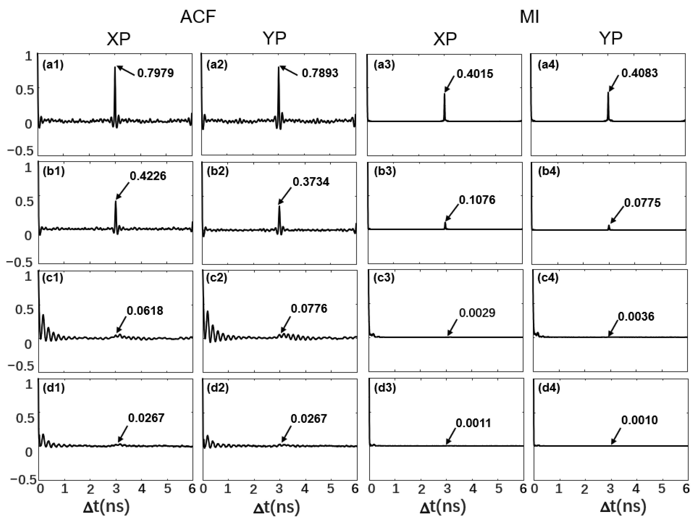
First, owing to the symmetric structure of the response VCSELs, the polarization-resolved output from VCSEL1 is investigated for simplicity in the following discussion of Figure 2, Figure 3, Figure 4 and Figure 5, and the external perturbation parameters are set as η = 10 ns−1, δ = 180 ns−1, and fm = 50 GHz, unless otherwise specified. For comparison, four driving laser configuration schemes are considered. They are conventional mirror feedback (Mirror), mirror feedback combined with an EO loop (Mirror + Loop), standalone FBG feedback (FBG), and the proposed TSBC scheme as shown in Figure 2(a1–d4), respectively. Obviously, both XP and YP exhibit very similar ACF and MI. As shown in Figure 2(a1–a4), the results reveal that the Mirror scheme exhibits a pronounced TDS at the feedback delay. The corresponding ACF and MI peaks are 0.7979 (0.7893) and 0.4015 (0.4083) for XP (YP), respectively. Such significant periodic features render the system vulnerable to phase space reconstruction attacks. For the Mirror + Loop scheme in Figure 2(b1–b4), nonlinear perturbations are introduced to weaken time-delay correlation under the same baseline conditions together with a loop feedback gain β = 5; nevertheless, its ACF peak of 0.4226 (0.3734) for XP (YP) remains discernibly high. In Figure 2(c1–c4), by replacing the mirror with an FBG, the frequency-selective feedback significantly enhances TDS suppression, and the ACF peak reduces to 0.0618 (0.0776) for XP (YP). Finally, the proposed TSBC scheme demonstrates the best TDS-suppression performance. As illustrated in Figure 2(d1–d4), under the proposed TSBC scheme, the ACF peak further decreases to 0.0267 (0.0267) for XP (YP), and the MI drops to 0.0011 (0.0010) for XP (YP). Although the absolute numerical reduction is subtle compared to the standalone FBG, the TSBC scheme effectively eliminates residual correlation and makes the time-delay peaks completely concealed in the background. The mechanism can be explained by the fact that the FBG feedback converts a fixed external-cavity round trip into frequency-dependent distributed feedback, and the EO loop further disrupts residual cavity coherence through nonlinear phase perturbations. This cooperation delivers a prominent synergistic effect that achieves superior performance beyond the individual TDS-suppression schemes.
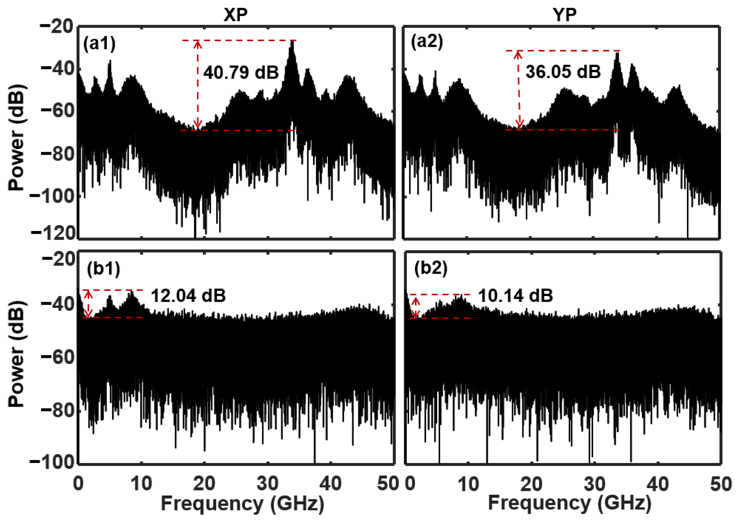
Additionally, the chaotic bandwidth of the carrier is another critical factor for chaotic communication capacity enhancement. Figure 3 compares the power spectra of the response VCSELs with standalone FBG feedback and the TSBC scheme for both polarization modes. The effective chaotic bandwidth is defined as the sum of the discrete high-power spectral segments in the chaotic power spectrum that collectively account for 80% of the total integrated power [38]. This metric avoids overestimating the chaotic bandwidth while simultaneously characterizing both the spectral coverage and the uniformity of the power distribution. Consequently, it provides a more accurate and rigorous evaluation of the actual spectral utilization efficiency of broadband chaotic carriers. For the standalone FBG feedback, the spectrum exhibits obvious spectral clustering and multiple localized peaks with unequal intensities. A strong spectral enhancement is observed around 35 GHz; however, it does not align with the frequency detuning of fm = 50 GHz, and pronounced spectral dips exist near 20 GHz, which reveal a nonuniform chaotic energy distribution. These deviations result from the nonlinear coupling of the laser’s relaxation oscillation frequency and the finite gain bandwidth [39]. Consequently, due to the poor spectral flatness, the chaotic energy is highly concentrated with quite limited effective bandwidths of 3.97 GHz (XP) and 6.13 GHz (YP), as shown in Figure 3(a1,a2). Quantitatively, the power variation [40] are as large as 40.79 dB (XP) and 36.05 dB (YP) for these cases. In contrast, for the TSBC scheme shown in Figure 3(b1,b2), the power spectra evolve into a smoother and flatter broadband distribution across nearly the entire bandwidth up to 50 GHz, with the power variations drastically reduced to only 12.04 dB (XP) and 10.14 dB (YP). It results from the introduction of phase perturbations and nonlinear phase-to-intensity mapping in the EO loop, which effectively redistributes the power of chaotic carriers in a wide frequency range and mitigates deterministic oscillation components. Compared with the standalone FBG feedback configuration, the TSBC scheme generates a more uniform spectral power distribution, and the bandwidths of the XP and YP increase to 23.27 GHz and 23.85 GHz, which are approximately four times larger than those of the standalone FBG feedback scheme.
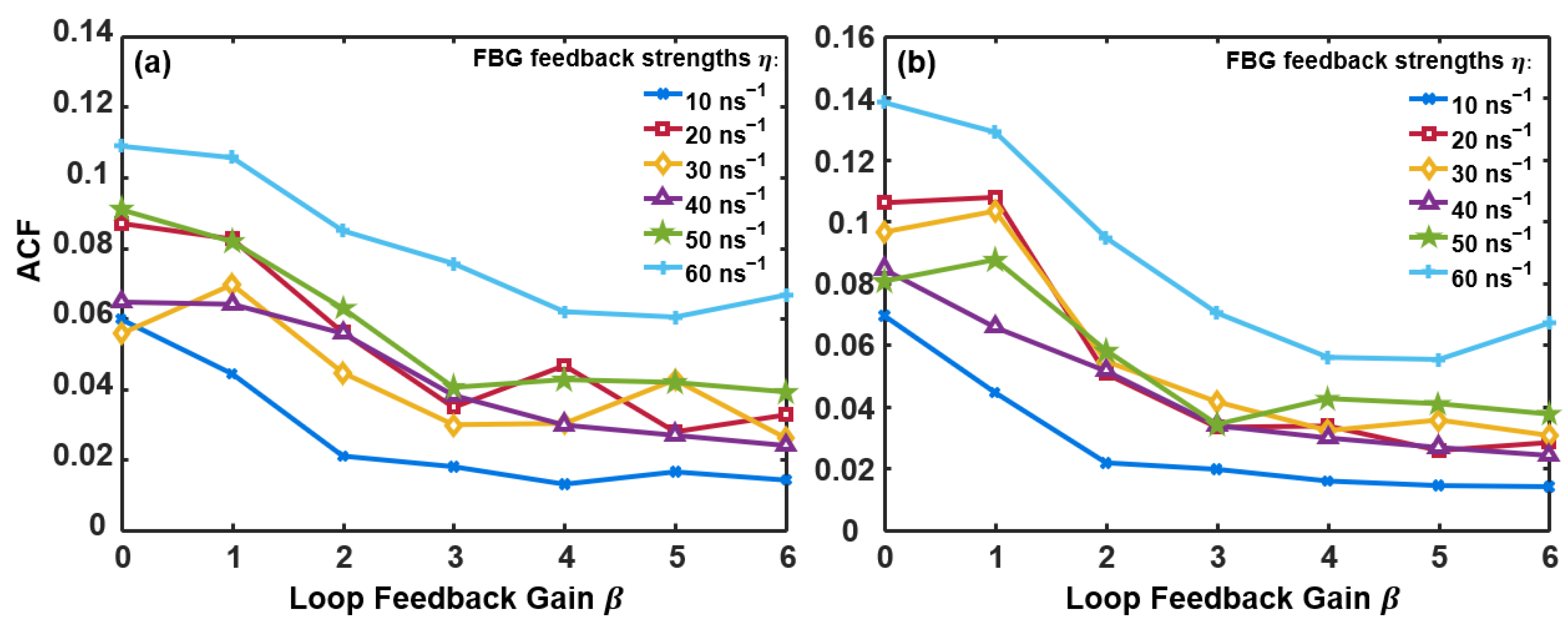
Next, it is necessary to explore the parameter ranges of the TSBC scheme for simultaneously achieving TDS-free and broadband chaotic outputs from the response VCSELs. Figure 4 illustrates the TDS evolution as a function of the EO loop gain β for different FBG feedback strengths η, while Figure 5 shows the chaotic bandwidth map for both XP and YP in a parameter space of FBG feedback strength η and EO loop gain β. In Figure 4, it can be observed that as β gradually increases from zero, the TDS peaks in both polarization modes exhibit a pronounced decreasing trend. For low FBG feedback strength η = 10 ns−1, the TDS decreases monotonically as β increases and reaches values below 0.02 for β ≥ 3. When the FBG feedback strength increases, the TDS curves gradually shift toward higher values, particularly for high FBG feedback strength η = 60 ns−1. Nevertheless, even in these cases, the TDS almost remains below the acceptable threshold of 0.1. For moderate FBG feedback strengths, the TDS exhibits a rapid decrease at low EO loop gain β, followed by weak fluctuations at larger β. Such fluctuations suggest competition between the delayed optical feedback introduced by the FBG and the nonlinear perturbation generated by the EO feedback loop. The lowest TDS values are generally obtained for β within values from 3 to 5, which indicates that an appropriate EO loop gain can further improve the TDS-suppression performance.
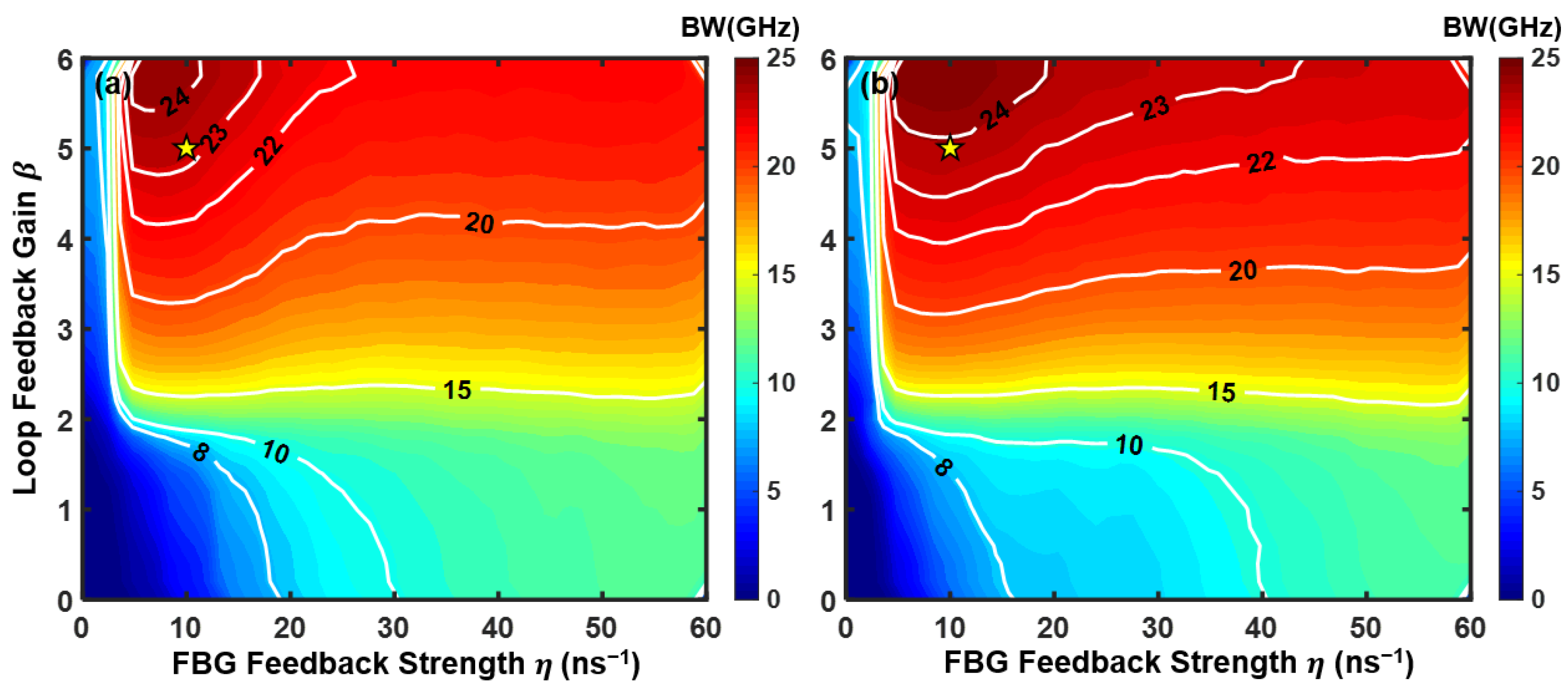
In Figure 5, for both polarization modes, the chaotic bandwidth of the response VCSEL gradually increases with the enhancement of the EO loop feedback gain β and the FBG feedback strength η. Compared with the increase in η, the increase in β results in a more pronounced expansion of the chaotic bandwidth, which indicates that the nonlinear phase modulation introduced by the EO loop plays a dominant role in the chaotic spectral broadening process. However, in the weak FBG feedback region approximately η < 5 ns−1, the bandwidth enhancement remains relatively limited despite the increase in β. Similarly, for low EO loop gain (β < 2), the chaotic bandwidth exhibits no significant improvement even when the feedback strength is increased. This behavior can be attributed to the failure to establish sufficient nonlinear coupling when either the EO loop feedback or the FBG feedback is weak, which results in laser dynamics dominated by low-dimensional chaotic oscillation or even quasi-periodic oscillation. As a result, the high-frequency chaotic components cannot be effectively excited, which restricts the expansion of the chaotic bandwidth. Therefore, jointly considering the TDS suppression, chaotic bandwidth, and practical device constraint [41,42], the operation point marked by the yellow stars at η = 10 ns−1 and β = 5 in the figure is selected as the optimal operating point for the driving VCSEL with the TSBC scheme. Under this condition, the ACF peak of the chaotic output remains stably below 0.03 for both polarization modes, while the driving VCSEL simultaneously achieves a relatively large chaotic bandwidth.
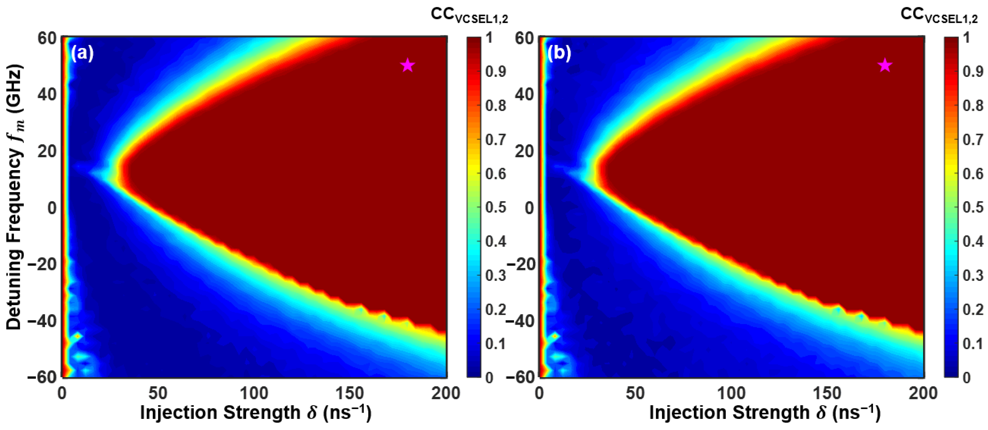
Following the optimization of the TSBC parameters, the synchronization performance as well as the chaotic carrier bandwidth under different optical injection parameters are studied next. Figure 6 shows the peak cross-correlation (CC) coefficients in the parameter space of injection strength δ and frequency detuning fm to quantitatively evaluate the synchronization performance between response VCSEL1 and VCSEL2, while Figure 7 presents the polarization-resolved chaotic carrier bandwidth of the response VCSEL1 in the parameter space of optical injection parameters. In Figure 6, it can be observed that, for weak injection strength, the CC coefficient remains low over nearly the entire frequency detuning range. When the injection strength exceeds approximately 30 ns−1, an obvious synchronization region is observed for sufficiently large injection strengths, where the CC coefficient remains close to 1 over a broad frequency detuning range. It should be noticed that the synchronization boundary is asymmetric; this is because of the amplitude-phase coupling characteristics of mutually coupled VCSEL dynamics, which have been observed in previous bidirectional chaotic communication systems [36]. XP and YP channels have very similar synchronization performance, which fundamentally enables dual-polarization channel chaotic communication.
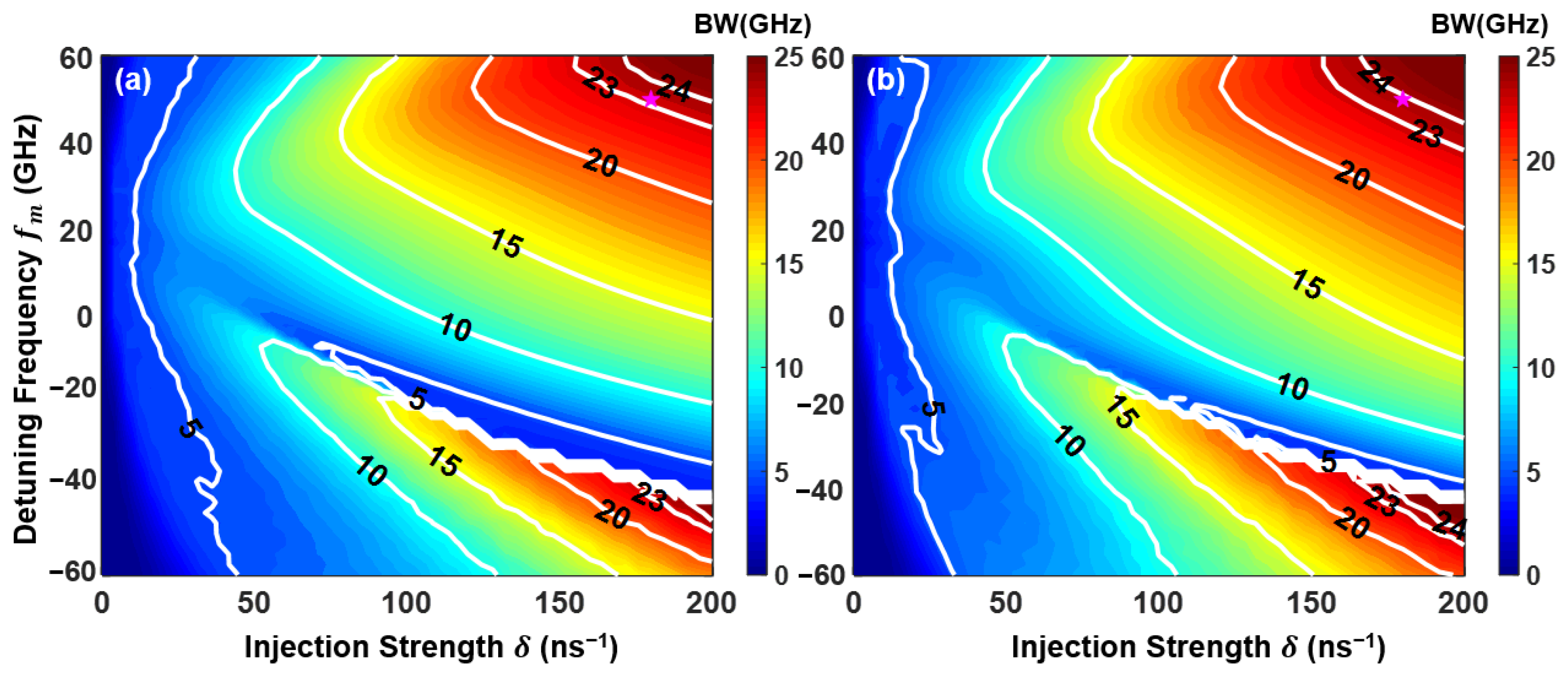
In Figure 7, under weak injection strengths below approximately 50 ns−1, the chaotic carrier effective bandwidth remains relatively limited, and the value stays below 10 GHz within almost the whole frequency detuning range. As the injection strength increases beyond 50 ns−1, a distinct high bandwidth region emerges, where the carrier bandwidth rises significantly to above 24 GHz across a broad range of frequency detuning. This high bandwidth region also exhibits an asymmetric distribution, which is similar to the asymmetry of the synchronization region induced by the α factor-induced shift in the Hopf and saddle-node bifurcation boundaries. Consequently, the optimized optical injection point is marked by the purple stars at δ = 180 ns−1 and fm = 50 GHz, where excellent synchronization performance with a CC coefficient close to 1 is achieved whilst the chaotic carrier bandwidth can be further extended to around 24 GHz.
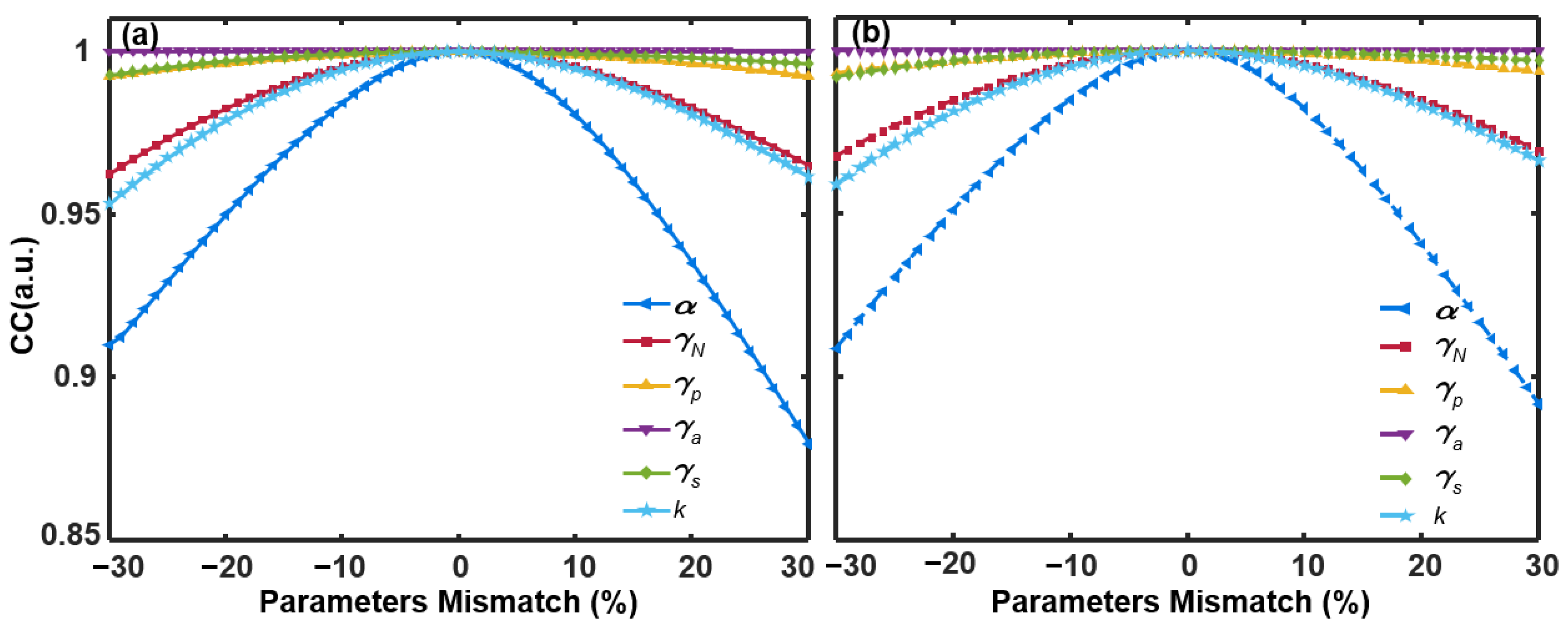
In practical semiconductor device fabrication, achieving an exact match of intrinsic parameters between the transmitter and the receiver is virtually impossible. Consequently, the evaluation of synchronization robustness under parameter mismatch is of paramount significance. In this work, the parameters of VCSEL1 are fixed, while the parameters of VCSEL2 are varied to simulate realistic deviations. The parameter mismatch rate is defined as the relative percentage deviation [43]. All results presented in Figure 8 are obtained at the optimal operating point determined in the preceding analysis, with η = 10 ns−1, β = 5, δ = 180 ns−1, and fm = 50 GHz. Figure 8 shows the peak CC coefficients for six intrinsic parameters within the mismatch range from −30% to 30%. It can be seen that the linewidth enhancement factor α performs the most significant influence on synchronization quality, which results from the phase-amplitude coupling effect and seriously affects the dynamics of VCSELs [43]. Nevertheless, the CC value stays above 0.9 for mismatches up to approximately 27%. Additionally, the system exhibits higher tolerance toward other parameters such as k and γN, where the peak CC coefficients remain consistently above 0.95 within the mismatch range. It should be noted that the aforementioned analysis considers individual parameter mismatches only. However, in practical applications, multiple parameters typically suffer from simultaneous variations and mismatches, which may further degrade the chaotic synchronization performance.
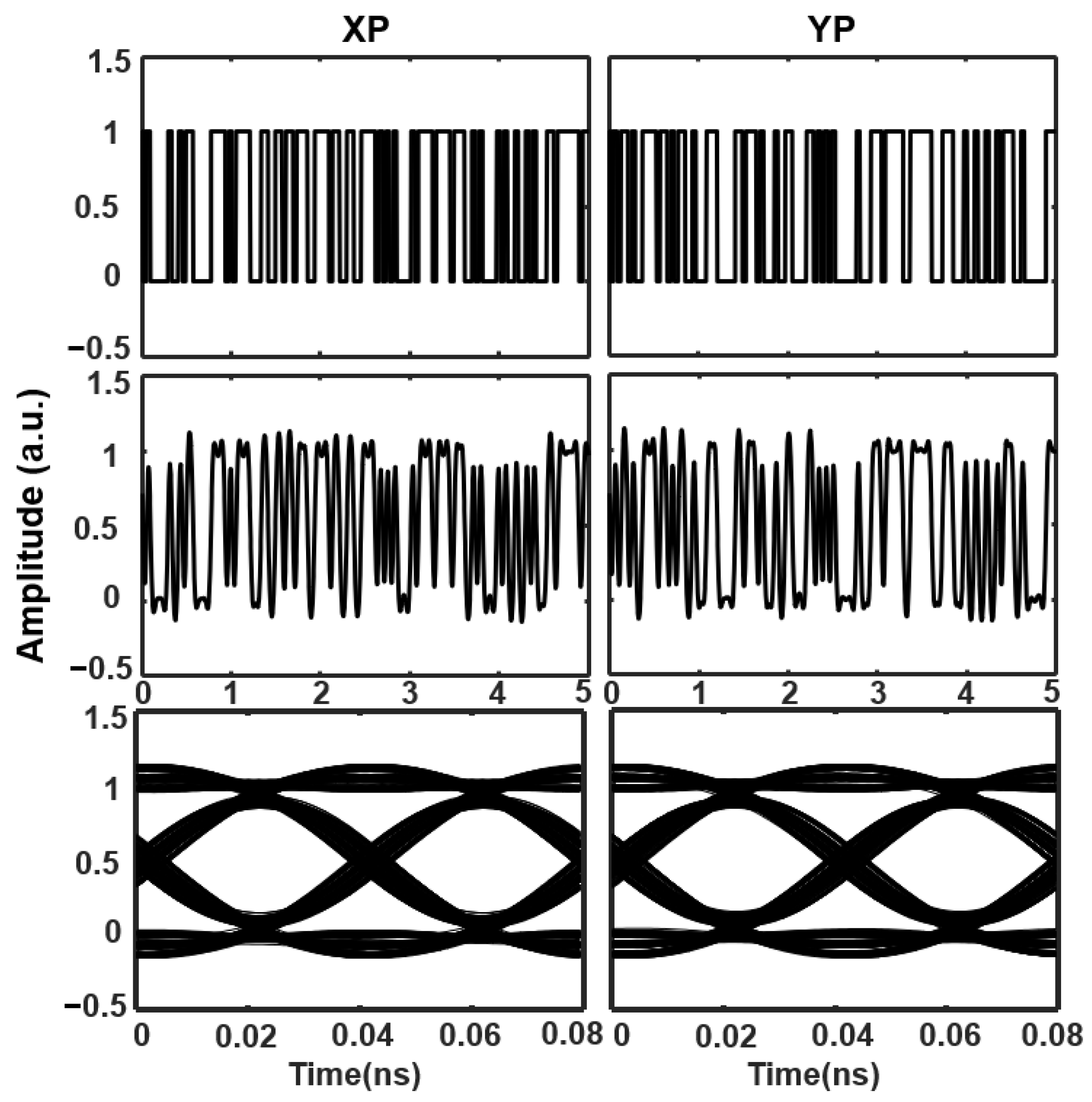
Based on the high-quality chaos synchronization as well as the TSBC carriers obtained from the above discussion, a chaos masking (CMS) scheme is employed to explore the chaotic transmission performance of the proposed TSBC dual-channel bidirectional secure communication system. Given the symmetrical response VCSEL configuration, we take the output from VCSEL1 as an example. During message loading, the modulation index is fixed at 0.05 with a bit rate of 23 Gbit/s, and the chaotic carriers from VCSEL1 are employed for the encoding of multiple messages E x , y 1 ( t ) = E x , y 1 ( t ) ( 1 + m M x , y ( t ) ) [43]. At the receiver, the synchronized chaotic carriers are subtracted from the received signal. A fourth-order Butterworth low-pass filter is adopted to suppress the residual high-frequency chaotic noise and recover the messages in both orthogonal polarization modes. As illustrated in Figure 9, the first row shows the original message sequences for the XP and YP channels, the second row presents the corresponding decoded messages, and the third row displays the eye diagrams of the decoded messages. The decoded temporal waveforms match the original digital sequences in both channels. Moreover, the eye diagrams exhibit wide and clear openings with high symmetry and low distortion, which indicates acceptable signal recovery performance.
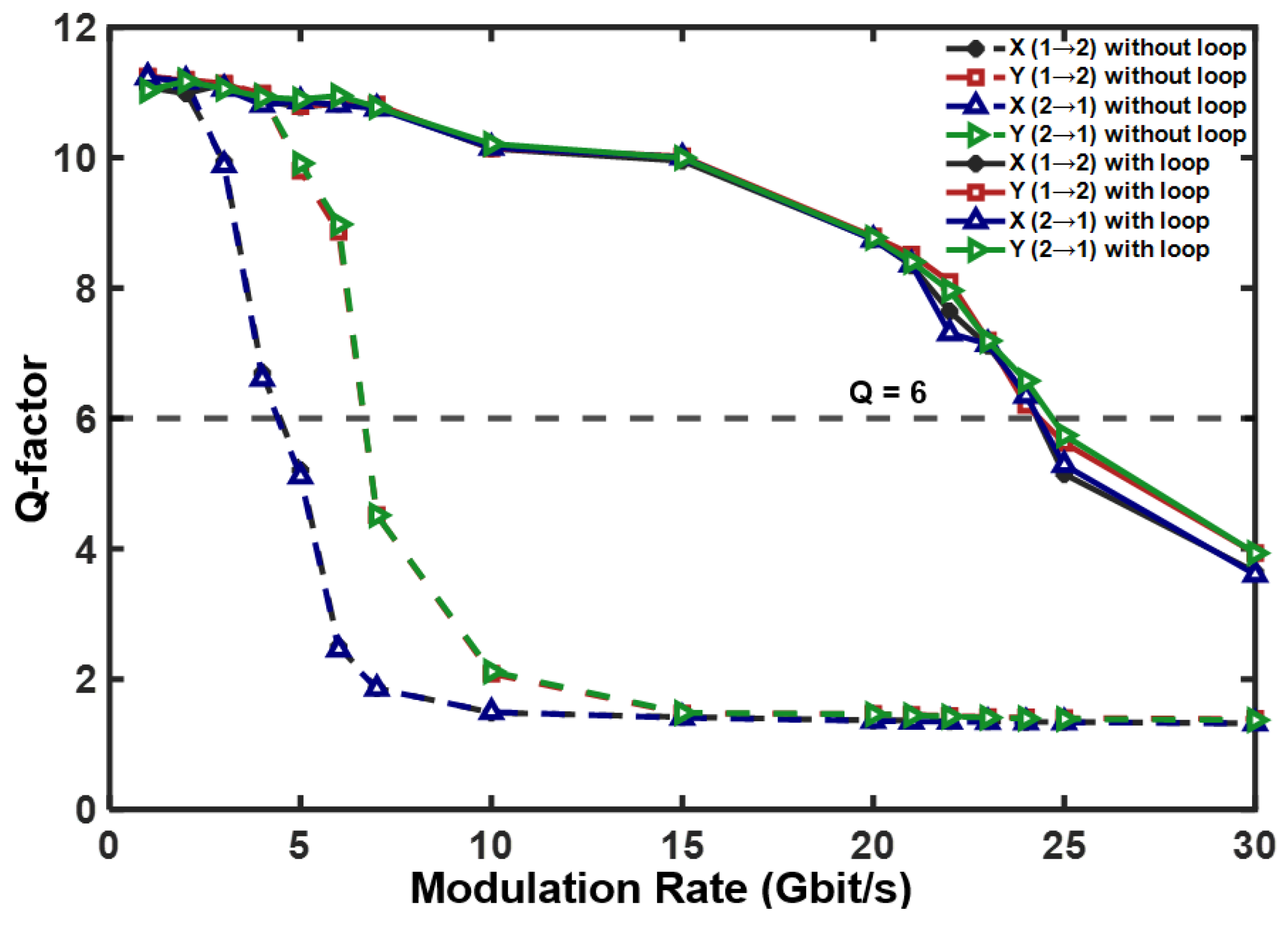
To quantitatively evaluate the transmission performance of the proposed TSBC dual-channel bidirectional chaotic secure communication system, the Q-factor is introduced, which has been widely adopted in chaotic secure communication systems for transmission performance evaluation [6]. Figure 10 compares the Q-factor versus modulation rate for bidirectional transmission between VCSEL1 and VCSEL2 with both polarization channels. As shown in Figure 10, without the external EO loop, the Q-factor decreases rapidly with increasing modulation rate due to the limited chaotic bandwidth under standalone FBG feedback and falls below the critical threshold of 6 at approximately 5 Gbit/s and 7 Gbit/s for the XP and YP channels, respectively. This behavior arises because the effective chaotic carrier bandwidth fundamentally constrains the achievable transmission rate in chaotic communication systems [44]. A broader chaotic spectrum provides a larger effective spectrum for message encoding and transmission, thereby supporting higher data rates. Also, the transmission performance is influenced by synchronization quality, noise, and detector bandwidth limitations [45]. And the chaotic carrier bandwidth of YP is slightly larger than that of XP without the EO loop, as shown in Figure 3(a1,a2). In contrast, when the TSBC scheme is introduced, the transmission performance of the system maintains the value of Q-factor above the critical threshold of 6 up to a modulation rate of 23 Gbit/s for each polarization channel. Moreover, the Q-factor curves between the response VCSELs have almost identical trend, which demonstrates the effectiveness of bidirectional chaotic transmission. As a result, an aggregated transmission rate of 46 Gbit/s is demonstrated for dual-polarization channel bidirectional chaotic communication.

4. Discussion

The proposed TSBC scheme simultaneously addresses TDS suppression and chaotic bandwidth enhancement in optical chaos communication. By combining FBG feedback with an EO phase modulation loop, the system effectively suppresses the time-delay signature (TDS) while significantly broadening the chaotic spectrum. Additionally, high-quality chaos synchronization is achieved under variations in injection parameters and internal parameter mismatches. Moreover, synchronized VCSELs are employed to construct a dual-polarization bidirectional chaotic communication system, which enables high-speed and secure transmission through two orthogonal polarization modes. Previous TDS-suppression methods [14,15,16,17,18] and bandwidth-enhancement schemes [19,20,21,22] have successfully achieved their respective objectives. However, the simultaneous realization of low TDS, broadband chaos, high-quality synchronization, and high-speed communication remains relatively underexplored. The proposed TSBC scheme provides a more balanced solution for simultaneously enhancing communication security and transmission capacity. The results indicate that the proposed scheme offers a feasible approach for achieving these objectives in a VCSEL-based chaotic communication system.
The proposed system is compatible with commercially available photonic and optoelectronic devices, facilitating its practical implementation. Nevertheless, its performance in practical applications may be influenced by factors such as EO-loop stability, device bandwidth limitations, polarization alignment errors, and parameter mismatches between system components. Consequently, future work will focus on the experimental realization of the proposed TSBC dual-polarization bidirectional chaotic communication system and a comprehensive evaluation of its performance under realistic operating conditions.

5. Conclusions

In summary, this study proposes and theoretically demonstrates a dual-polarization bidirectional chaotic communication system based on VCSELs synchronized using the TSBC scheme. The synergistic integration of frequency-selective FBG feedback and an external EO phase modulation loop applied to the driving VCSEL significantly enhances both the physical layer security and transmission capacity by suppressing the time-delay signature (TDS) and enhancing the chaotic bandwidth, respectively. The results show that, compared to traditional mirror feedback or standalone FBG feedback, the TSBC scheme further suppresses the TDS to 0.0267. This result ensures that the TDS is effectively concealed in the background of the autocorrelation functions (ACFs) and mutual information (MI) curves. Moreover, the TSBC scheme utilizes nonlinear phase-to-intensity mapping facilitated by an MZI to induce obvious spectral broadening. As a result, the chaotic carrier bandwidth increases from 3.97 GHz (6.13 GHz) under standalone FBG feedback to over 23.27 GHz (23.85 GHz) for XP (YP), which corresponds to an approximately fourfold enhancement. Through the optimization of the FBG feedback strength and the loop gain, a balance between physical layer security and transmission capacity has been established. Furthermore, analysis of the injection-locking dynamics reveals that the system exhibits a broader synchronization range and superior robustness in the positive frequency detuning region. With the selected injection parameters, the chaotic carrier bandwidth of the response laser exceeds 23 GHz. Finally, an aggregated 46 Gbit/s dual-polarization channel bidirectional chaotic communication is achieved. This work demonstrates the effectiveness and strong potential of the TSBC dual-polarization bidirectional scheme in secure optical communication systems.

Author Contributions

Conceptualization, writing—original draft, X.H.; data curation, Y.Z., J.X. and H.Y.; writing—review editing, J.C. and C.T.; project administration, funding acquisition, Z.Z.; supervision, writing—review editing, Z.Z. and Y.H. All authors have read and agreed to the published version of the manuscript.

Funding

This research was funded by the National Natural Science Foundation of China, grant number 62265016 and 62205040; Natural Science Foundation of Chongqing, grant number CSTB2025NSCQ-GPX0238; Shiji Elite Talent Program and the Research and Innovation Team Cultivation Program Foundation of Chongqing University of Technology, grant number 2023TDZ0073.

Institutional Review Board Statement

Not applicable.

Informed Consent Statement

Not applicable.

Data Availability Statement

Data underlying the results presented in this paper are not publicly available at this time but may be obtained from the authors upon reasonable request.

Conflicts of Interest

The authors declare no conflicts of interest.

References

  1. Alansary, S.A.; Ayyad, S.M.; Talaat, F.M.; Saafan, M.M. Emerging AI threats in cybercrime: A review of zero-day attacks via machine, deep, and federated learning. Knowl. Inf. Syst. 2025, 67, 10951–10987. [Google Scholar] [CrossRef]
  2. Al Siam, A.; Faruqui, N.; Azad, A.; Moni, M.A. Securing the Unseen: A Comprehensive Exploration Review of AI-Powered Models for Zero-Day Attack Detection. Expert Syst. 2026, 43, e70217. [Google Scholar] [CrossRef]
  3. Zhu, Y.; Kellermann, A.; Gupta, A.; Li, P.; Fang, R.; Bindu, R.; Kang, D. Teams of llm agents can exploit zero-day vulnerabilities. In Proceedings of the 19th Conference of the European Chapter of the Association for Computational Linguistics; Association for Computational Linguistics: Rabat, Morocco, 2026; Volume 1: Long Papers, pp. 23–35. [Google Scholar]
  4. Mucchi, L.; Jayousi, S.; Caputo, S.; Panayirci, E.; Shahabuddin, S.; Bechtold, J.; Morales, I.; Stoica, R.-A.; Abreu, G.; Haas, H. Physical-layer security in 6G networks. IEEE Open J. Commun. Soc. 2021, 2, 1901–1914. [Google Scholar] [CrossRef]
  5. He, J.; Giddings, R.P.; Jin, W.; Hao, M.; Tang, J. Chaotic digital filter-based physical layer security with data-assisted tri-level encryption for heterogeneous access networks. J. Opt. Commun. Netw. 2025, 17, 448–458. [Google Scholar] [CrossRef]
  6. Li, N.; Pan, W.; Xiang, S.; Luo, B.; Yan, L.; Zou, X. Hybrid chaos-based communication system consisting of three chaotic semiconductor ring lasers. Appl. Opt. 2013, 52, 1523–1530. [Google Scholar] [CrossRef] [PubMed]
  7. Sciamanna, M.; Shore, K.A. Physics and applications of laser diode chaos. Nat. Photonics 2015, 9, 151–162. [Google Scholar] [CrossRef]
  8. Hou, T.; Yi, L.; Yang, X.; Ke, J.; Hu, Y.; Yang, Q.; Zhou, P.; Hu, W. Maximizing the security of chaotic optical communications. Opt. Express 2016, 24, 23439–23449. [Google Scholar] [CrossRef] [PubMed]
  9. Yang, Z.; Yi, L.; Ke, J.; Zhuge, Q.; Yang, Y.; Hu, W. Chaotic optical communication over 1000 km transmission by coherent detection. J. Light. Technol. 2020, 38, 4648–4655. [Google Scholar] [CrossRef]
  10. Chen, W.; Mao, X.; Wang, J.; Zhang, R.; Wang, L.; Jia, Z.; Li, P.; Wang, A.; Wang, Y. Optical chaos generation and applications. Adv. Photonics Res. 2025, 6, 2500055. [Google Scholar] [CrossRef]
  11. Li, P.; Cai, Q.; Zhang, J.; Xu, B.; Liu, Y.; Bogris, A.; Shore, K.A.; Wang, Y. Observation of flat chaos generation using an optical feedback multi-mode laser with a band-pass filter. Opt. Express 2019, 27, 17859–17867. [Google Scholar] [CrossRef] [PubMed]
  12. Wei, X.; Qiao, L.; Guo, Z.; Wang, X.; Li, J.; Zhang, M. Broadband and time-delay signature suppressed chaos generation in semiconductor laser subjected to microring resonator combined with optical injection. Chaos Solitons Fractals 2025, 196, 116417. [Google Scholar] [CrossRef]
  13. Rontani, D.; Locquet, A.; Sciamanna, M.; Citrin, D.S.; Ortin, S. Time-delay identification in a chaotic semiconductor laser with optical feedback: A dynamical point of view. IEEE J. Quantum Electron. 2009, 45, 879–1891. [Google Scholar] [CrossRef]
  14. Wu, J.-G.; Xia, G.-Q.; Wu, Z.-M. Suppression of time delay signatures of chaotic output in a semiconductor laser with double optical feedback. Opt. Express 2009, 17, 20124–20133. [Google Scholar] [CrossRef] [PubMed]
  15. Xiang, S.; Pan, W.; Luo, B.; Yan, L.; Zou, X.; Jiang, N.; Yang, L.; Zhu, H. Conceal time-delay signature of chaotic vertical-cavity surface-emitting lasers by variable-polarization optical feedback. Opt. Commun. 2011, 284, 5758–5765. [Google Scholar] [CrossRef]
  16. Hong, Y. Experimental study of time-delay signature of chaos in mutually coupled vertical-cavity surface-emitting lasers subject to polarization optical injection. Opt. Express 2013, 21, 17894–17903. [Google Scholar] [CrossRef] [PubMed]
  17. Li, S.-S.; Liu, Q.; Chan, S.-C. Distributed feedbacks for time-delay signature suppression of chaos generated from a semiconductor laser. IEEE Photonics J. 2012, 4, 1930–1935. [Google Scholar] [CrossRef]
  18. Wang, D.; Wang, L.; Guo, Y.; Wang, Y.; Wang, A. Key space enhancement of optical chaos secure communication: Chirped FBG feedback semiconductor laser. Opt. Express 2019, 27, 3065–3073. [Google Scholar] [CrossRef] [PubMed]
  19. Wang, B.; Qiao, L.; Wei, X.; Chai, M.; Zhang, M. Evolution of the time delay signature of chaos generated in three types of optical injection systems. Appl. Opt. 2023, 62, 4899–4905. [Google Scholar] [CrossRef] [PubMed]
  20. Chen, R.; Cai, Q.; Guo, P.; Zhang, J.; Li, P.; Alan Shore, K.; Qin, Y.; Wang, Y. Wideband chaos generation using VCSELs with intensity-modulated chaotic optical injection. Opt. Express 2025, 33, 10599–10608. [Google Scholar] [CrossRef] [PubMed]
  21. Han, H.; Cheng, X.M.; Jia, Z.W.; Shore, K.A. Suppression of cavity time-delay signature using noise-phase-modulated feedback. IEEE Access 2020, 8, 35344–35349. [Google Scholar] [CrossRef]
  22. Jiang, N.; Wang, Y.; Zhao, A.; Liu, S.; Zhang, Y.; Chen, L.; Li, B.; Qiu, K. Simultaneous bandwidth-enhanced and time delay signature-suppressed chaos generation in semiconductor laser subject to feedback from parallel coupling ring resonators. Opt. Express 2020, 28, 1999–2009. [Google Scholar] [CrossRef] [PubMed]
  23. Zhong, D.; Zhang, J.; Deng, W.; Hou, P.; Wu, Q.; Chen, Y.; Wang, T.; Hu, Y.; Deng, F. Optical cascaded reservoir computing for realization of dual-channel high-speed OTDM chaotic secure communication via four optically pumped VCSEL. Opt. Express 2023, 31, 21367–21388. [Google Scholar] [CrossRef] [PubMed]
  24. Zhang, X.; Wang, A.; Xu, J.; Sun, Y.; Mo, L.; Zhang, Y.; Qin, Y.; Wang, Y. Chaos synchronization of VCSELs with common injection of polarization-random light. Opt. Express 2023, 31, 35720–35729. [Google Scholar] [CrossRef] [PubMed]
  25. Fu, J.; Mu, P. Research on secure communication technology based on phase conjugate feedback chaotic injection system. J. Opt. 2024, 26, 065704. [Google Scholar] [CrossRef]
  26. Zhao, A.; Jiang, N.; Liu, S.; Xue, C.; Tang, J.; Qiu, K. Wideband complex-enhanced chaos generation using a semiconductor laser subject to delay-interfered self-phase-modulated feedback. Opt. Express 2019, 27, 12336–12348. [Google Scholar] [CrossRef] [PubMed]
  27. Zhong, Z.-Q.; Li, S.-S.; Chan, S.-C.; Xia, G.-Q.; Wu, Z.-M. Polarization-resolved time-delay signatures of chaos induced by FBG-feedback in VCSEL. Opt. Express 2015, 23, 15459–15468. [Google Scholar] [CrossRef] [PubMed]
  28. Zhong, Z.-Q.; Wu, Z.-M.; Song, J.; Wang, L.-Y.; Deng, T.; Xia, G.-Q. Polarization dynamics of 1550-nm VCSELs subject to polarization-preserved FBG feedback. IEEE Photonics Technol. Lett. 2016, 28, 963–966. [Google Scholar] [CrossRef]
  29. Zhong, Z.-Q.; Wu, Z.-M.; Xia, G.-Q. Experimental investigation on the time-delay signature of chaotic output from a 1550 nm VCSEL subject to FBG feedback. Photonics Res. 2016, 5, 6–10. [Google Scholar] [CrossRef]
  30. Zhu, X.; Cheng, M.; Deng, L.; Jiang, X.; Ke, C.; Zhang, M.; Fu, S.; Tang, M.; Shum, P.; Liu, D. An optically coupled electro-optic chaos system with suppressed time-delay signature. IEEE Photonics J. 2017, 9, 6601009. [Google Scholar] [CrossRef]
  31. Li, Y.; Wu, Z.-M.; Zhong, Z.-Q.; Yang, X.-J.; Mao, S.; Xia, G.-Q. Time-delay signature of chaos in 1550 nm VCSELs with variable-polarization FBG feedback. Opt. Express 2014, 22, 19610–19620. [Google Scholar] [CrossRef] [PubMed]
  32. Erdogan, T. Fiber grating spectra. J. Light. Technol. 1997, 15, 1277–1294. [Google Scholar] [CrossRef]
  33. Chembo Kouomou, Y.; Colet, P.; Larger, L.; Gastaud, N. Chaotic breathers in delayed electro-optical systems. Phys. Rev. Lett. 2005, 95, 203903. [Google Scholar] [CrossRef] [PubMed]
  34. Deng, T.; Xia, G.; Wu, Z. Broadband chaos synchronization and communication based on mutually coupled VCSELs subject to a bandwidth-enhanced chaotic signal injection. Nonlinear Dyn. 2014, 76, 399–407. [Google Scholar]
  35. Cui, B.; Jiang, S.; Yang, W. Time delay signature concealment of chaotic output in a master-slave vertical-cavity surface-emitting lasers system. Opt. Express 2025, 33, 32130–32139. [Google Scholar] [CrossRef] [PubMed]
  36. Wang, H.; Lu, T.; Ji, Y. Key space enhancement of a chaos secure communication based on VCSELs with a common phase-modulated electro-optic feedback. Opt. Express 2020, 28, 23961–23977. [Google Scholar] [CrossRef] [PubMed]
  37. Su, B.-B.; Chen, J.-J.; Wu, Z.-M.; Xia, G.-Q. Performances of time-delay signature and bandwidth of the chaos generated by a vertical-cavity surface-emitting laser under chaotic optical injection. Acta Phys. Sin. 2017, 66, 244206. [Google Scholar] [CrossRef]
  38. Lin, F.-Y.; Chao, Y.-K.; Wu, T.-C. Effective bandwidths of broadband chaotic signals. IEEE J. Quantum Electron. 2012, 48, 1010–1014. [Google Scholar] [CrossRef]
  39. Lau, E.K.; Sung, H.-K.; Wu, M.C. Frequency response enhancement of optical injection-locked lasers. IEEE J. Quantum Electron. 2007, 44, 90–99. [Google Scholar] [CrossRef]
  40. Hong, Y. Flat broadband chaos in mutually coupled vertical-cavity surface-emitting lasers. IEEE J. Sel. Top. Quantum Electron. 2015, 21, 652–658. [Google Scholar] [CrossRef]
  41. Larger, L. Complexity in electro-optic delay dynamics: Modelling, design and applications. Philos. Trans. R. Soc. A Math. Phys. Eng. Sci. 2013, 371, 20120464. [Google Scholar] [CrossRef] [PubMed]
  42. Wang, C.; Ji, Y.; Wang, H.; Bai, L. Security-enhanced electro-optic feedback phase chaotic system based on nonlinear coupling of two delayed interfering branches. IEEE Photonics J. 2018, 10, 7203415. [Google Scholar] [CrossRef]
  43. Liu, J.; Wu, Z.-M.; Xia, G.-Q. Dual-channel chaos synchronization and communication based on unidirectionally coupled VCSELs with polarization-rotated optical feedback and polarization-rotated optical injection. Opt. Express 2009, 17, 12619–12626. [Google Scholar] [CrossRef] [PubMed]
  44. Argyris, A.; Syvridis, D.; Larger, L.; Annovazzi-Lodi, V.; Colet, P.; Fischer, I.; Garcia-Ojalvo, J.; Mirasso, C.R.; Pesquera, L.; Shore, K.A. Chaos-based communications at high bit rates using commercial fibre-optic links. Nature 2005, 438, 343–346. [Google Scholar] [CrossRef] [PubMed]
  45. Kanakidis, D.; Argyris, A.; Syvridis, D. Performance characterization of high-bit-rate optical chaotic communication systems in a back-to-back configuration. J. Light. Technol. 2003, 21, 750. [Google Scholar] [CrossRef]
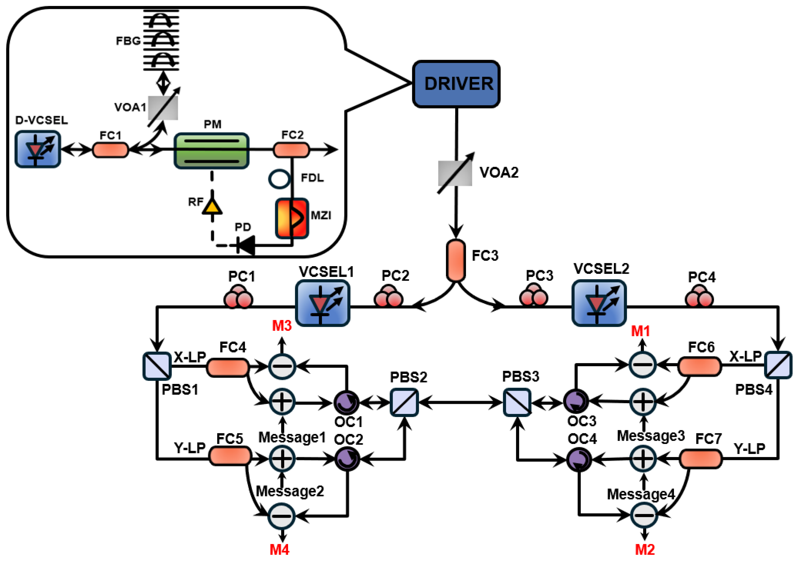
Figure 1. Setup of the proposed dual-polarization channel chaotic communication system with synchronized VCSELs driven by a TSBC scheme. D-VCSEL, driving VCSEL; FC, fiber coupler; FBG, fiber Bragg grating; PM, phase modulator; FDL, fiber delay line; MZI, Mach–Zehnder interferometer; PD, photodetector; RF, radio-frequency amplifier; VOA, variable optical attenuator; PC, polarization controller; PBS, polarization beam splitter; and OC, optical circulator.
Photonics 13 00592 g001
Figure 2. The ACF and MI of response laser chaotic carrier outputs from (a1a4) Mirror, (b1b4) Mirror + Loop, (c1c4) FBG, and (d1d4) the proposed TSBC scheme.
Photonics 13 00592 g002
Figure 3. The power spectra of response laser for (a1,a2) FBG and (b1,b2) the proposed TSBC scheme.
Photonics 13 00592 g003
Figure 4. The TDS evolution as a function of the EO loop feedback gain β under different FBG feedback strengths η: (a) XP and (b) YP.
Photonics 13 00592 g004
Figure 5. Two-dimensional evolution of the chaotic bandwidth of the response VCSEL in the parameter space of FBG feedback strength η and loop feedback gain β. The yellow stars denote the optimized operating point for the TSBC scheme. (a) XP and (b) YP.
Photonics 13 00592 g005
Figure 6. Two-dimensional evolution of the peak CC coefficients in the (a) XP and (b) YP in the parameter space of injection strength δ and frequency detuning fm. The purple stars indicate the optimized operating point.
Photonics 13 00592 g006
Figure 7. Two-dimensional evolution of the chaotic carrier bandwidth for (a) XP and (b) YP of VCSEL1 in the parameter space of injection strength δ and frequency detuning fm. The purple stars indicate the optimized operating point.
Photonics 13 00592 g007
Figure 8. Peak CC coefficients between VCSEL1 and VCSEL2 in both (a) XP and (b) YP versus six mismatched internal parameters.
Photonics 13 00592 g008
Figure 9. Original messages (first row), decoded messages (second row), and eye diagrams (third row) of decoded messages.
Photonics 13 00592 g009
Figure 10. Q-factor as a function of modulation rate for dual-channel bidirectional transmission with and without the external EO feedback loop. The dashed line indicates Q = 6.
Photonics 13 00592 g010
Table 1. The key parameters of the system.
ParmeterDescriptionValue
kfield decay rate300 ns−1
αlinewidth enhancement factor3
μnormalized injection current2.7
γalinear cavity dichroism0.1 ns−1
γplinear birefringence10 ns−1
γNtotal carrier decay rate1 ns−1
γsspin-flip rate50 ns−1
βspspontaneous emission factor1 × 10−6 GHz
κBcoupling coefficient of the FBG100 m−1
nggroup index of the fiber1.45
Llength of the FBG20 mm
θlow cut-off time5 μs
εhigh cut-off time18 ps
Ttotal loop delay time25 ns
Timbalanced delay time of the interferometer0.4 ns
Φ0offset interference phaseπ/4
Disclaimer/Publisher’s Note: The statements, opinions and data contained in all publications are solely those of the individual author(s) and contributor(s) and not of MDPI and/or the editor(s). MDPI and/or the editor(s) disclaim responsibility for any injury to people or property resulting from any ideas, methods, instructions or products referred to in the content.