1. Introduction
The light-emitting diode (LED) is a new generation of light source, with the advantages of energy saving, environmental protection, and high efficiency [
1,
2,
3,
4]. Without secondary light distribution, the lighting effects of LEDs cannot meet the requirements in certain lighting situations because of their Lambertian irradiation distribution. For instance, in industrial precision inspection scenarios (e.g., non-contact defect detection of PCB circuit boards, precision dimension measurement of micro-components), a uniform and compact illumination system is critically required; uneven illumination may cause missed detection or false alarms, and space constraints in automated production lines demand high compactness [
5]. Accordingly, to improve the lighting performance of LED, a secondary light distribution design is required.
In recent years, the research on LED lighting has made great progress, especially in the field of reflective and refractive lighting. The redistribution of emitted light by catadioptrics is an effective method for improving illumination performance. H. Ries and J. Muschaweck obtained a uniform energy or illuminance distribution by tailoring the surface of the reflectors or lens [
6]. Tsuei used the deflection characteristics to design an LED illumination system to reduce glare problems in indoor lighting [
7]. Therefore, in the practical application of LED lighting, a secondary light distribution design is essential to ensure that the light energy distribution meets practical lighting requirements [
8,
9]. In addition, Moiseev proposed a numerical direct optimization to directly optimize double freeform surfaces and concluded that a single freeform surface is more difficult to achieve high efficiency with than double-freeform-surface systems [
10]. Wu proposed a direct optimization of a rotation-symmetry, compact, double-freeform-surface illumination system that achieves very high lighting efficiency and performance [
11]. The above method improved the uniformity of the illumination system. However, traditional reflectors or refractive lenses have high requirements for processing precision and materials. In addition, in many cases, diffuse reflection must be used to improve the uniformity of an illumination system, such as in industrial inspections or real life [
12,
13,
14]. Usually, light diffusion leaves a surface in all directions rather than at an identical angle as with specular reflections, which makes the reflected light uniform at almost any angle [
14,
15,
16,
17]. Therefore, light diffusion is more suitable for industrial inspection than catadioptric systems. Therefore, it is necessary to improve the uniformity of a diffuse-reflection illumination system. In our previous work, the design method of a single freeform diffuse-reflection surface was applied to the illumination system, and the illumination uniformity was improved [
18,
19,
20]. However, in the above design method, the center beam of the illumination system was difficult to fully diffuse, which made it difficult to further increase the uniformity of the illumination. In addition, the thickness-to-diameter ratio of the illumination system obtained by applying these design methods to enhance uniformity was usually greater than 1:2, which does not reflect the advantages of the compactness of the LED illumination system.
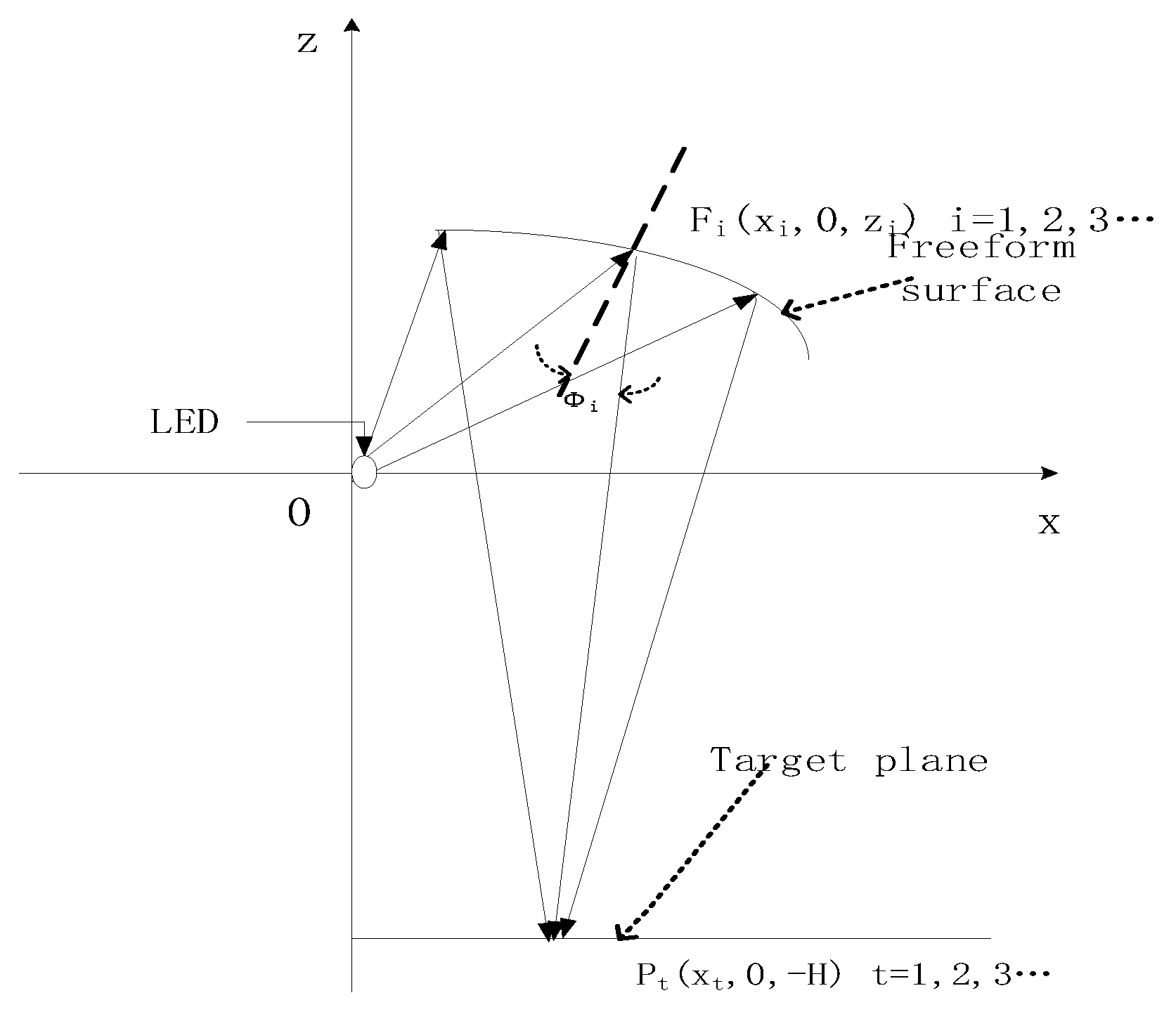
In summary, industrial production and testing have a certain demand for diffused light. Diffuse light is more friendly to the human eye than catadioptric light. However, diffuse light is less controllable than catadioptric light. To address the aforementioned shortcomings and limitations, this study proposes an LED illumination system based on combined freeform surfaces with specular and diffuse reflections. In contrast to display technologies, industrial inspection prioritizes the spatial uniformity of diffuse irradiance to distinguish subtle defects (e.g., scratches and bubbles) rather than absolute uniformity values. The proposed combined freeform surface system is tailored to these industrial needs, addressing the gap in compact, high-uniformity diffuse illumination for non-display applications, where traditional systems fall short. First, the surface of the specular reflection horizontally diffuses the center beam of the LED toward the diffuse-reflection surface, and the surface of the diffuse-reflection portion reassigns all the beams emitted by the LED to the target plane. As shown in
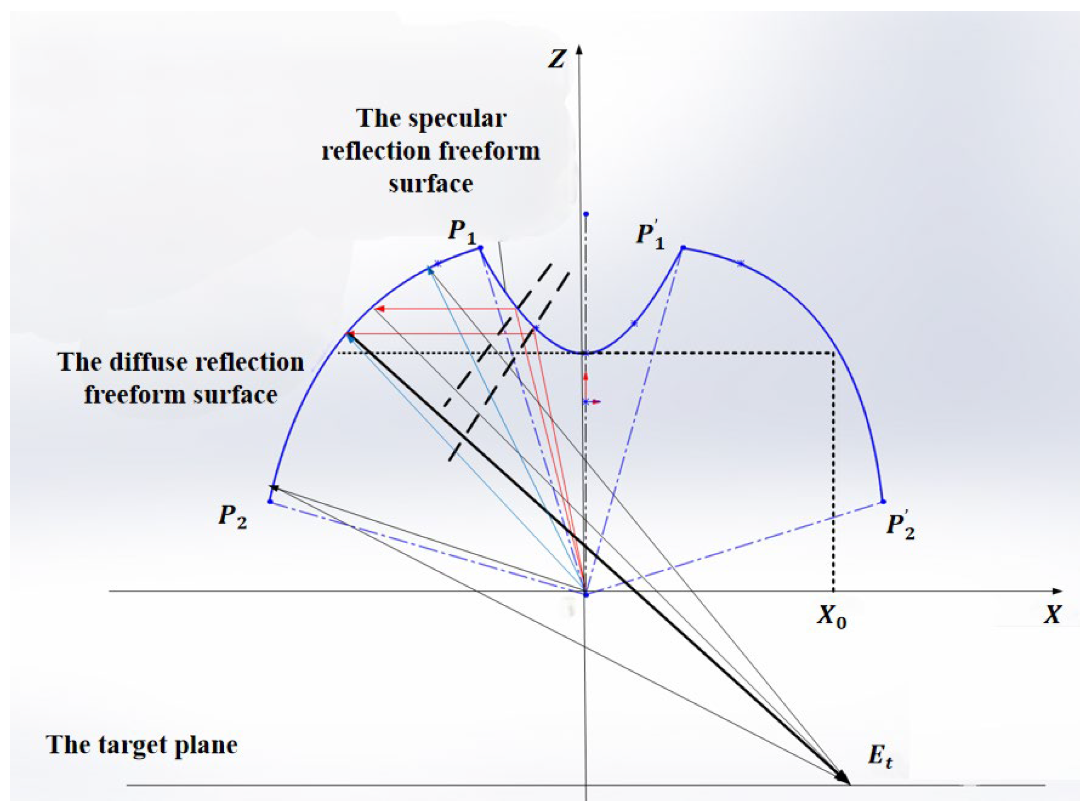
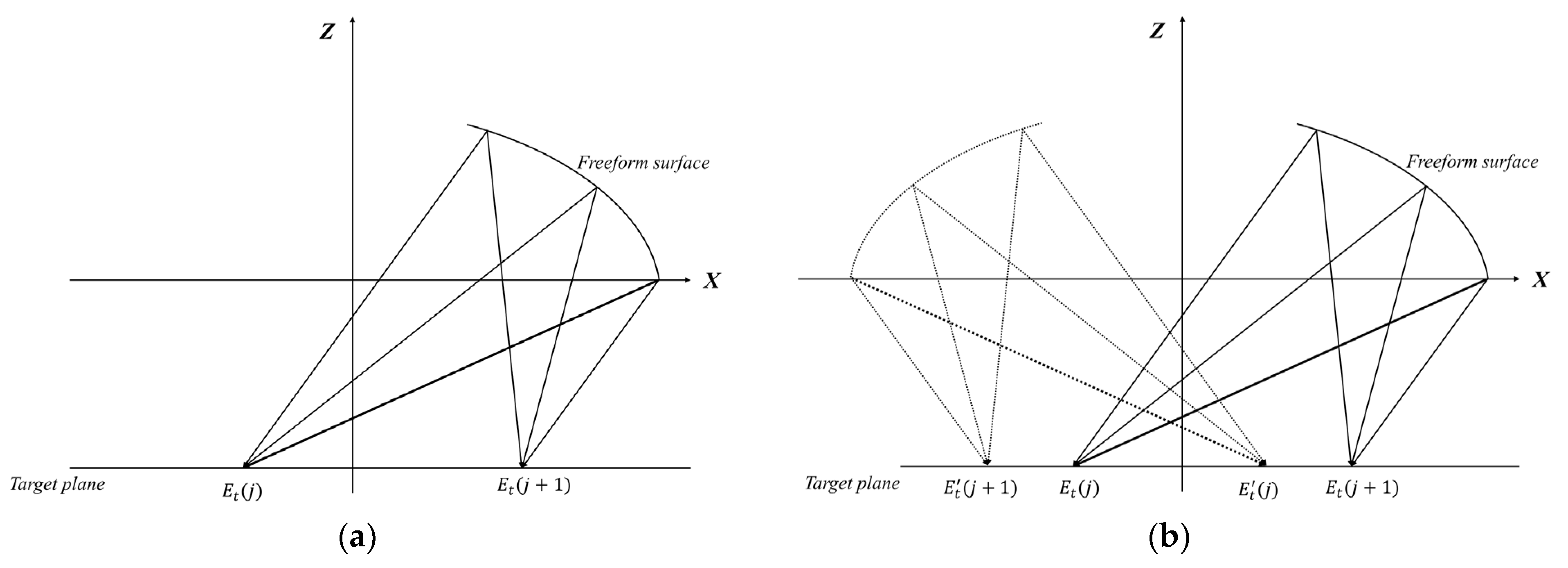
Figure 1, when designing a diffuse freeform surface, we use a constraint relationship that equals the sum of the irradiance values of a point on the target plane and its mirror point to establish a set of nonlinear equations. Solving this nonlinear equation yields the linear profile of the diffuse-deflection freeform surface, and the complete freeform surface is obtained by rotation about the
z-axis. Simulations show that the illumination system obtained using the proposed design method has a smaller size (diameter-to-thickness ratio > 6) and higher uniformity (>56%) than traditional diffuse-reflection illumination systems, making it well-suited for industrial precision inspection scenarios with strict requirements on uniformity and space.
2. Design of Combined Freeform Surfaces
Figure 2 shows the cross-sectional profile of the combined-freeform-surface illumination system with an LED at the origin. The rays emitted from the source are divided into two parts: one part, marked with a red line in
Figure 1, is reflected laterally by the specular-reflection freeform surface onto the diffuse-reflection freeform surface, and the other part, marked with a blue line, is reassigned to the target plane by the diffuse-reflection freeform surface along with the previous rays.
We will discuss the above two freeform surface design methods in the following two steps.
2.1. The Design of the Specular-Reflection Freeform Surface
The specular-reflection freeform surface is designed to precisely redirect the central beam of the LED (emission angle ≤ 40°) to the diffuse-reflection surface, ensuring that the central light (which is difficult to fully diffuse in single-freeform-surface designs) can be uniformly redistributed. The design follows the principle of ray tracing combined with the law of reflection. For each discrete point on the specular surface, we calculate the required tangent slope by establishing the relationship between the incident rays, reflected rays, and surface normal, thereby constructing the continuous contour of the freeform surface.
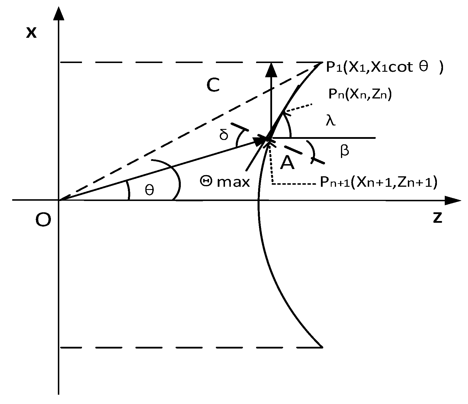
As shown in
Figure 3, we first derive the ray equation where the
point is located. The slope of the ray equation for the
is
. Therefore, the light equation passing through
is given by Equation (1).
The slope of the tangent equation of the curve set at
is
, and the curve passes
, so the tangent equation has the following form.
Since the sum of
β and
is equal to 2/pi,
is equal to
. From Snell’s law of reflection, it can be seen that the angle
is equal to
. Assuming that the slope of the normal vector at the
of the curve is
k, there is k equal to (−1)/
. As in Equation (3), according to the nip angle formula, the slope relationship between the tangent equation and the ray equation can be obtained.
According to Equation (3), can be obtained, and then the tangent equation can be obtained. It is considered that the neighbors () of the point are also on the same tangent. Discretization of yields a series of continuous nonlinear equations. Solve the equations and fit the aspheric coefficients of the specular freeform surface.
The specular-reflection freeform surface obtained through the above equations and solution process can redirect 100% of the LED central beam to the upper half of the diffuse-reflection surface (as shown in
Figure 2). This ensures that the central light, which was underutilized in traditional single-freeform-surface designs, is fully involved in the uniform redistribution of the diffuse surface, laying the foundation for improving the overall illumination uniformity of the system.
2.2. The Design of the Diffuse-Reflection Freeform Surface
We divided the second freeform surface into upper and lower parts and designed them separately. As shown in
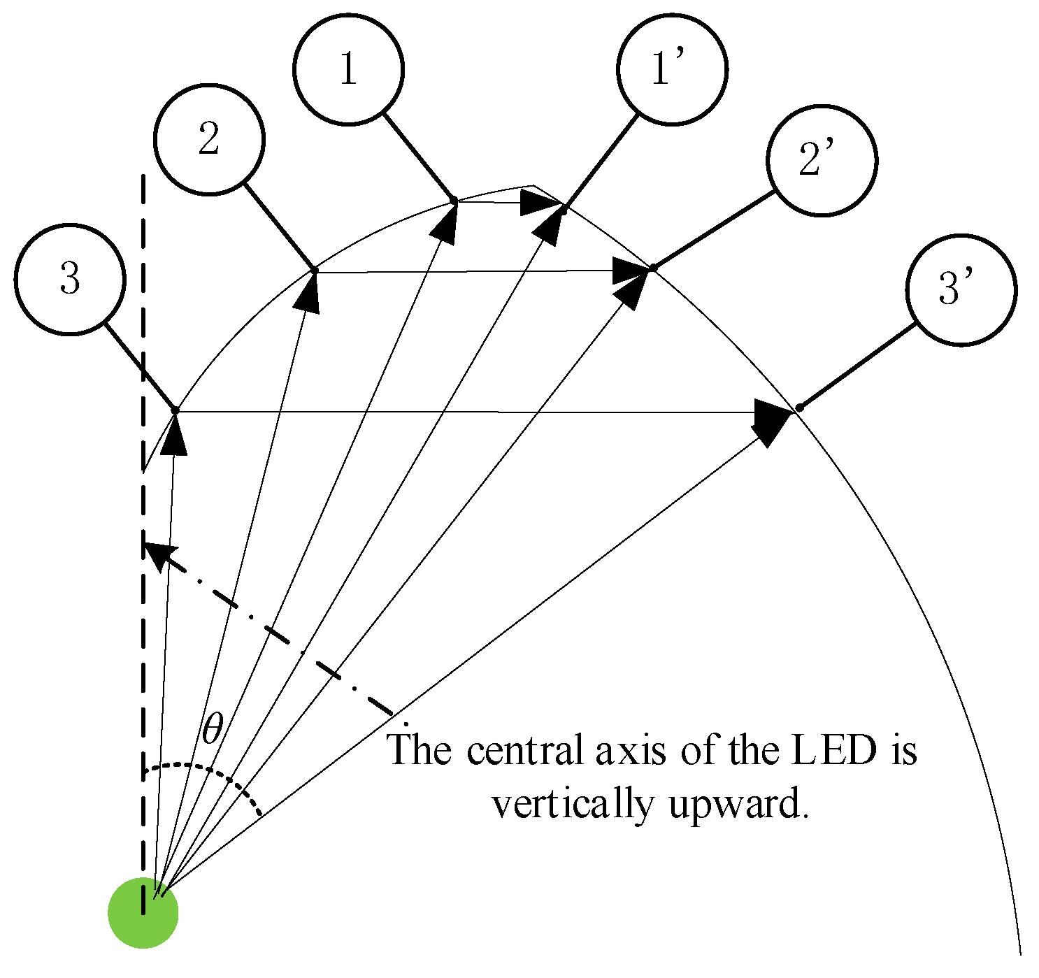
Figure 4, the expression of the irradiance on the freeform surface of the upper part is given by Equation (4). Divided by the blue dotted line, the left side is the outline of the specular component, and the right side is the outline of the diffuse component. The points marked 1, 2, and 3 are the radiation points that are directly projected from the center of the LED to the specular-reflection component. The points marked
are the superimposed radiant points of the specular-reflection component projecting light and the large-angle exiting rays of the LED on the diffuse-reflection component. The diffuse-reflection component is divided into upper and lower parts by a red dotted line in the figure. The illuminance of the upper part was the superimposed irradiance of the above, and the illuminance of the lower part was only the direct illuminance of the LED.
Here
is the distribution of reflected irradiance on the upper freeform surface,
is the distribution of direct irradiance of the LED on the upper freeform surface, and
is the total irradiance on the upper freeform surface.
indicates the irradiation intensity of the LED in the axial direction.
indicates the intersection angle between the direction of the light emission and the axial direction of the LED. The diffuse-reflection freeform surface is regarded as a series of continuously distributed secondary LED light sources. As shown in
Figure 5, it is assumed that the light vector emitted from the freeform surface is
and the normal vector on the surface is
. According to the space vector’s parameters, we can get the following expression:
where
dx and
dz represent the differential of
x and
z, respectively.
is the included angle between
and
.
is the coordinates on the target surface.
H is a constant that represents the distance between the target plane and the LED. In this paper, the freeform inner surface is defined as a Lambertian surface. It is also called an ideal diffuse-reflection surface with the cosine characteristic expressed as Equation (6). The reflected light emitted from this freeform inner surface is scattered equally in random directions.
where
is the emergent light intensity at a certain emitting angle and
is the maximum radiant intensity in the vertical direction of the freeform inner surface. Accordingly, the reflected irradiance distribution of the target plane can be expressed as Equation (7).
where
E is the received irradiance of the freeform inner surface given by Equation (4).
is the distance between the freeform surface and the target plane.
ds represents the area element on the freeform surface.
B represents the B-directional reflectance distribution function (BRDF), which is used to describe the uniformity of light with random direction in space. It can be given by the following [
5]:
Considering the practical condition, the diffuse-reflectance ratio
of the freeform inner surface is 0.85 in our calculations. The reflected irradiance distribution of the target plane, given by Equation (7) in complex integral form, is replaced by a simple irradiance superposition from all these secondary sources:
where
is the number of the discrete points that we sampled on the freeform surface. Discretize the target plane and get the irradiation value expression at any point on the target plane.
where
is the coordinate on the
-axis in the target plane and
is the number of discrete points. Assume that the mirror point of
is
. The expression of the mirror irradiation value of Equation (10) is obtained.
In accordance with the principle of illuminance uniformity, the sum of the irradiance values at any arbitrary point on the target plane and its corresponding mirror point is constant.
The above formula is integrated into Equation (12), and (13) can be obtained.
Here,
is equal to 1, 2, 3, …,
u − 1. Solving the series of nonlinear equations, we get the upper-half part of the linear contour of the diffuse-reflection freeform surface and rotate it around the
-axis to get the surface. Using a similar method, the expressions of the irradiation value and the mirror irradiation value of the freeform surface in the lower half on the target plane are Equation (14) and Equation (15), respectively.
where
is the irradiance distribution expression of the illumination system on the freeform surface of the lower half.
According to the principle of illuminance uniformity, the sum of the irradiation value of each point and its mirror point on the target plane is equal.
Used in the same introduction method as described above. Solving the series of nonlinear equations, we get the lower-half part of the linear contour of the freeform surface and rotate it around the -axis to get the surface.
2.3. Combined Expressions for the Combined Freeform Surfaces
2.3.1. Coordinate System Definition
The LED point source is located at the origin (0,0,0) of the Cartesian coordinate system. The target plane is parallel to the xz-plane and located at (where H denotes the distance between the LED and the target plane). The combined freeform surfaces are rotationally symmetric around the z-axis, so the 3D design can be simplified to a 2D profile in the xz-plane, with the full 3D surface obtained by rotating the 2D profile around the z-axis.
2.3.2. Combined Expression for the Specular-Reflection Freeform Surface
The specular-reflection freeform surface redirects the central beam of the LED (small emission angle
) to the diffuse-reflection surface. Its profile is derived based on the law of reflection and ray tracing, with the following combined expression:
where
and
are adjacent discrete points on the specular freeform surface;
is the angle between the tangent line at
and the
x-axis;
and
are the angles between the normal vector at
and the incident/reflected rays, respectively (satisfying the law of reflection
=
);
is the angle between the incident ray (from LED to
) and the
x-axis; and
is the slope of the normal vector at
.
2.3.3. Combined Expression for the Diffuse-Reflection Freeform Surface
The diffuse-reflection freeform surface is divided into upper () and lower (z > 0) halves, both designed based on the mirror-point irradiance constraint. The combined expression integrates the irradiance superposition principle, Lambertian reflection model, and uniformity constraint.
Upper half of diffuse surface (superimposed irradiance from specular-reflected beams and direct large-angle LED beams) can be expressed as Equation (4).
Lower half of diffuse surface (only direct irradiance from LED) can be expressed as Equation (16).
- 2.
Target Plane Irradiance and Uniformity Constraint
The target plane irradiance is the superposition of contributions from all discrete secondary sources on the diffuse surface. For any point on the target plane and its mirror point , the uniformity constraint requires:
The combined expression for the target plane irradiance and uniformity constraint is as follows:
where
(upper half) or
(lower half),
(diffuse reflectance of the inner surface),
(number of discrete points on the diffuse surface),
(differentials of discrete coordinates).
- 3.
Continuous Profile of the Diffuse Surface
Solving the above nonlinear system yields discrete points on the diffuse surface, which are fitted with aspheric equations.
3. Design Example
According to the above method, the LED was modeled as a point source for the initial mathematical derivation and system-level performance validation, as the system working distance (50–500 mm) was 22–221 times the LED chip size, satisfying the far-field condition for the point-source approximation. The short chip-to-freeform surface distance (2–3 mm) has a negligible impact on the final target plane illumination owing to the uniform redistribution effect of the diffuse-reflection freeform surface, and it has an analogous Lambertian radiation distribution, with a power of 1 w (a chip size of 1.6 mm × 1.6 mm (junction area ~2.56 mm2)). The radius of the target plane varied from to , and the distance between the corresponding illumination system and target plane varied from to . To prove the effectiveness of the proposed design method, we compared the illumination efficiency and illumination uniformity of three illumination systems: combined freeform diffuse-reflection surfaces, traditional single freeform diffuse-reflection surfaces, and traditional integrating sphere diffuse-reflection surfaces. To follow the single principle of variables, the transverse diameters of all comparative illumination systems in this study were equal to the lateral diameter of the designed illumination system. The illumination system at a relatively optimum height for this diameter was found by adjusting the radial height of the illumination system. Finally, the lighting performance of all lighting systems was compared.
The emission angle of the LED light source was divided into small and large angles. The small angle exiting light diffuses through the specular-reflection component onto the diffuse reflector component. Light emitted at a large angle is projected directly onto the diffuse reflector component. The final diffuse component redistributes all of the collected light to the target surface based on the principle of uniformity of illumination.
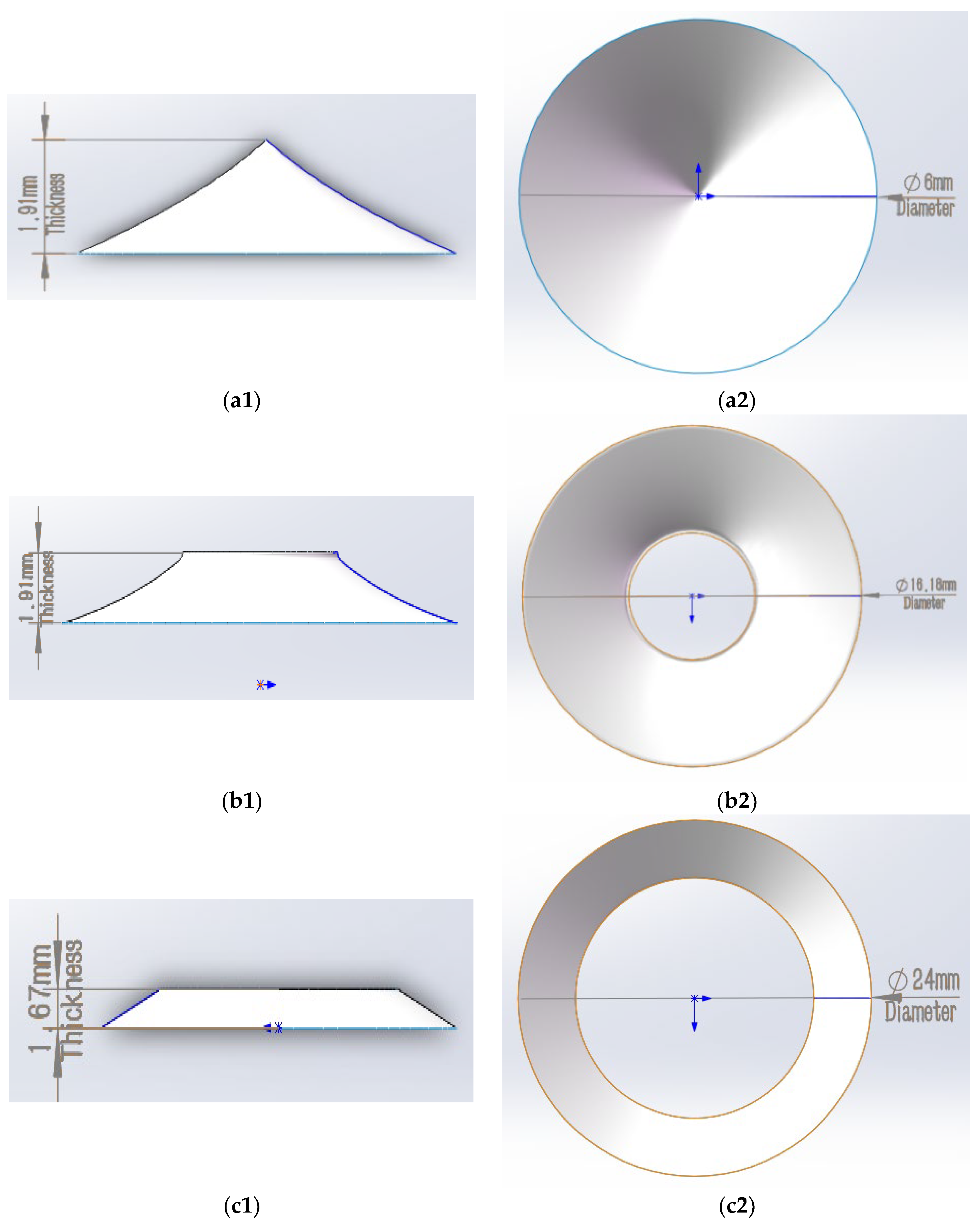
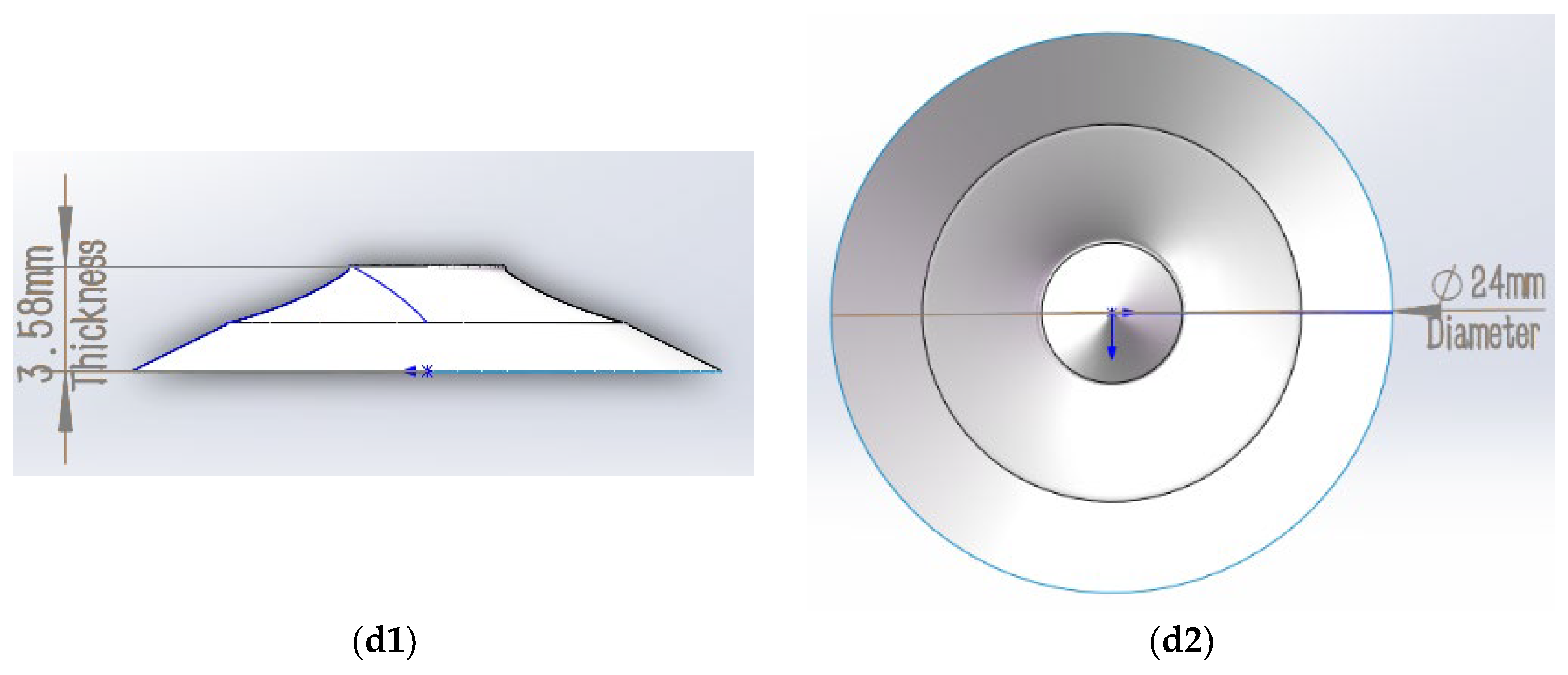
Figure 6 and
Table 1 show the outlines and dimensions used in this experiment. The split angle between the mirror and diffuse surfaces was
. The thickness and diameter of the specular-reflection surface are
and
, respectively. The thickness and diameter of the diffuse-reflection freeform surface’s upper half are
and
and those of the lower half are
and
, respectively. It integrates three core components: a specular-reflection freeform surface (
Section 2.1), an upper diffuse-reflection freeform surface, and a lower diffuse-reflection freeform surface (
Section 2.2). The specular-reflection surface is located at the inner center of the system, whereas the upper and lower diffuse-reflection surfaces form a continuous enclosure around it, with the upper surface overlapping and connecting to the specular surface at points
and
(as labeled in
Figure 2).
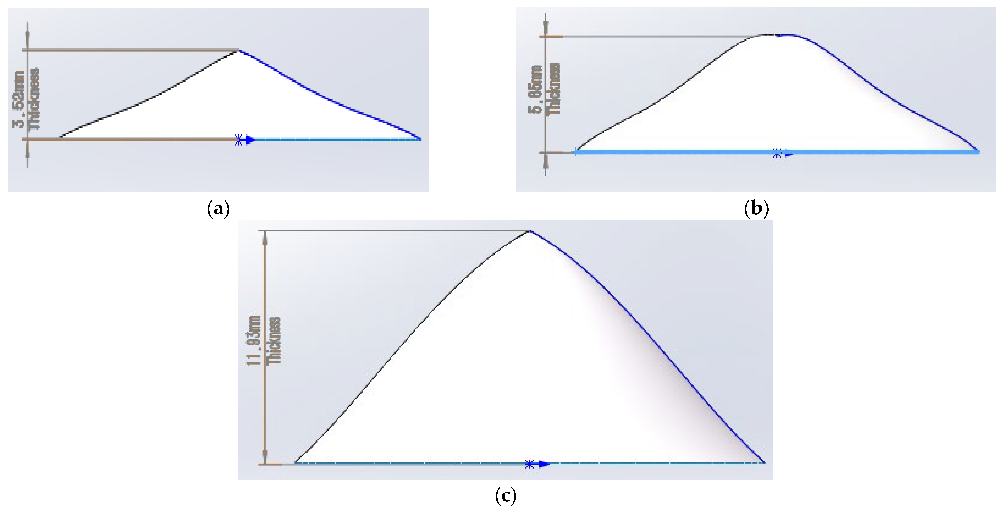
Figure 7 and
Table 2 show the outlines and dimensions of the corresponding traditional single freeform diffuse-reflection surface, and presents three traditional single freeform diffuse-reflection surfaces (labeled “a”, “b”, “c”) used for performance comparison with the proposed combined system. All three surfaces are rotationally symmetric around the z-axis, with the same diameter of 24 mm (consistent with the combined system to ensure fair comparison) but different axial thicknesses (3.52 mm, 5.85 mm, 11.93 mm) and average curvature radii (18.6 mm, 25.3 mm, 32.1 mm), respectively (
Table 2 and
Table 3). To verify the effectiveness of this design method, three illumination systems with different thicknesses of single freeform diffuse-reflection surfaces with the same diameter of
are selected for comparison.
To ensure transparency and reproducibility, we provide the complete parameters of the traditional single freeform diffuse-reflection surfaces used in the comparative simulations (
Table 2 in the original manuscript) in
Table 3.
We used the TracePro (version 7.8.3) software for the simulation tests to verify the system performance.
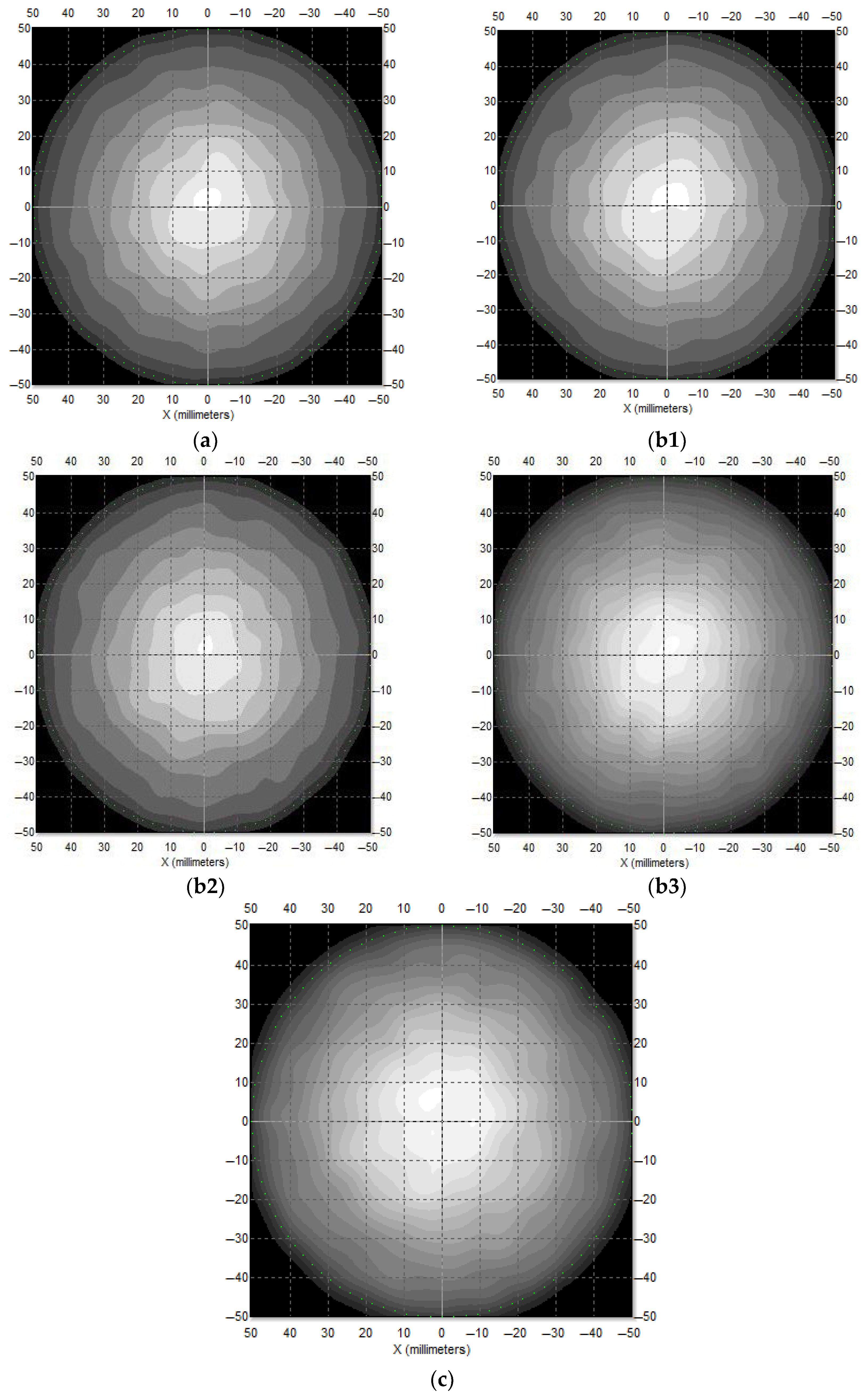
Figure 8 shows the circular spot patterns of the three illumination systems with a radius of
at the
distance. From left to right, the figure shows the traditional integrating sphere diffuse-reflection surface illumination system, traditional single-freeform-diffuse-reflection-surface illumination system with three different thicknesses, and combined-freeform-surface illumination system. It can be clearly seen from
Figure 8 that the illumination uniformity of the last two figures is higher than that of the above three figures. In addition, in this case, the uniformity of the single-freeform-diffuse-reflection-surface illumination system will be significantly improved only when the illumination system is relatively thick.
Table 4 and
Table 5 show the lighting performance of the three illumination systems under different lighting conditions. As shown in
Table 1, the illumination uniformity of the traditional integrating sphere diffuse-reflection-surface illumination system is the lowest, and the uniformity of the traditional diffuse-reflection single-freeform-surface illumination system increases with increasing system thickness. However, among the three different illumination systems, the uniformity of the combined-freeform-diffuse-reflection-surface illumination system was significantly enhanced. As shown in
Table 2, the three illumination systems had similar lighting efficiencies under the same lighting conditions. Among them, the illumination efficiency of the traditional integrating sphere (the standard commercial integrating sphere module and its material and structural parameters are consistent with the typical specifications of integrating spheres used in similar diffuse-illumination research) diffuse-reflection-surface illumination system was the lowest, and the efficiency of the traditional diffuse-reflection single-freeform-surface illumination system decreased slightly. Among the three different illumination systems, the combined-freeform-diffuse-reflection-surface illumination system was relatively moderate. According to
Table 1 and
Table 2, the combined-freeform-diffuse-reflection-surface illumination system has a more stable lighting performance than the traditional diffuse-reflection single-freeform-surface illumination system.
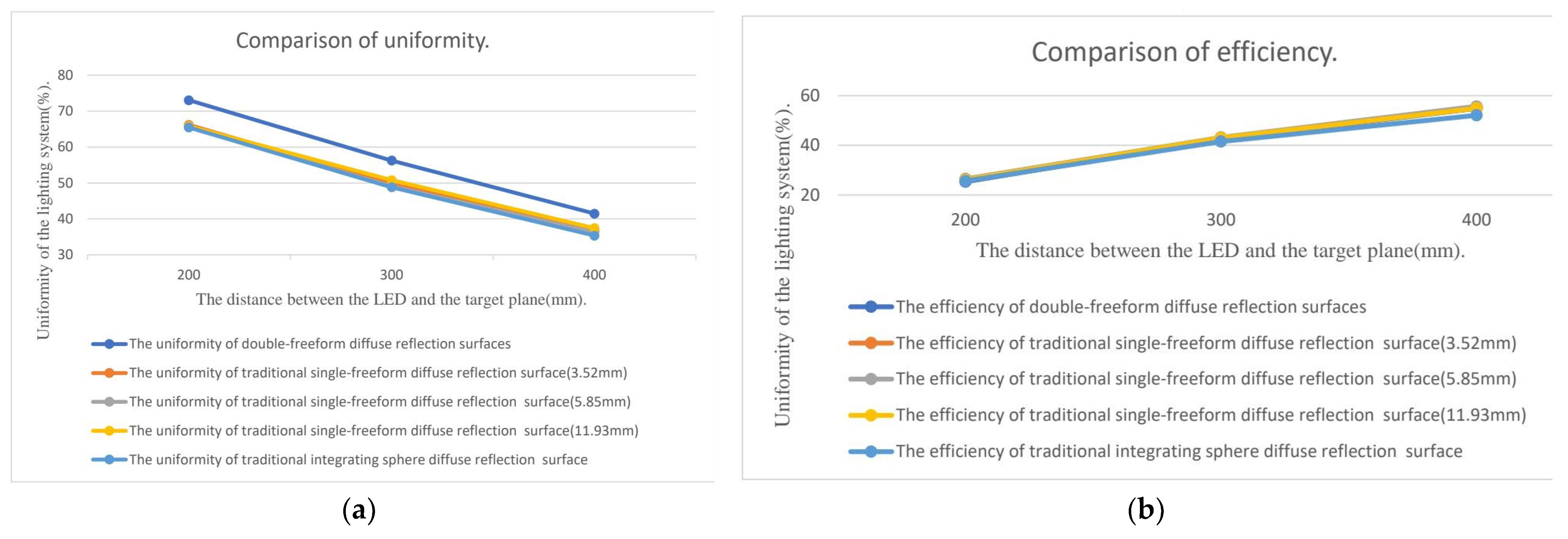
Figure 9 shows the lighting performance of the three illumination systems in different target lighting areas at the same lighting distance. As shown in the figure, the illumination uniformity of the designed combined-freeform-diffuse-reflection-surface illumination system is significantly and steadily improved compared with the other two conventional diffuse-illumination systems. Simultaneously, it can be seen from
Figure 9 that the illumination system designed in this paper improves the uniformity without sacrificing the efficiency.
4. Discussion
The design and simulation validation of the combined-freeform-surface diffuse-reflection illumination system addresses critical gaps in the current LED secondary optical design, particularly for high-uniformity and compact diffuse-illumination applications. In the domain of diffuse-reflection, our prior work [
18,
19,
20] introduced single freeform diffuse surfaces to improve uniformity; however, the central beam diffusion remained inadequate, and the thickness-to-diameter ratio (>1:2) failed to leverage the compactness of LEDs. The combined-freeform system proposed in this study resolves these issues by integrating the specular- and diffuse-reflection components. The specular freeform surface redirects the central LED beam to the diffuse component, ensuring full diffusion of all emitted light, which is an improvement over single-freeform designs, where the central beams are poorly controlled. This design choice aligns with the principle that the targeted redirection of light (via specular reflection) can enhance the controllability of diffuse light, which is inherently less manageable than collimated or specularly reflected light.
The proposed combined-freeform-surface illumination system is specifically designed for industrial inspection and precision measurement scenarios, where its balanced performance in uniformity, compactness, and diffuse light quality addresses unmet needs of conventional solutions. Concrete application cases include: (1) Inline defect detection for automotive components (e.g., plastic casings, metal surfaces), where the system’s long working distance (50–500 mm) and compact form factor enable integration into automated production lines, eliminating shadows and glare to identify micro-scratches and surface contamination; (2) portable electronic component testing (e.g., printed circuit boards, semiconductor wafers), where the diameter-to-thickness ratio (>6) facilitates handheld operation, and the soft diffuse light protects operators’ eyes during prolonged inspections; (3) dimensional measurement of non-planar parts (e.g., curved glass, injection-molded products), where uniform spatial irradiance ensures consistent imaging quality for machine vision algorithms. Compared to traditional industrial illumination systems: Integrating spheres (uniformity ≤ 50.88%) suffer from bulkiness and low efficiency, making them unsuitable for space-constrained setups; single-freeform-surface systems require excessive thickness (≥11.93 mm) to achieve moderate uniformity (≤53.76%), which conflicts with industrial compactness demands. The proposed system’s uniformity (56.06–57.52%) and compact design meet the practical requirements of most industrial inspection tasks, where the core goal is to enhance defect detection accuracy rather than pursue display-level uniformity.
While this work demonstrates significant advancements, several avenues for future research remain. First, the current design assumes a point light source; however, practical LEDs have extended emitting areas. Future studies should incorporate the finite size of LED chips into the mathematical model to account for the edge effects and improve the accuracy of the optical design. This could involve modifying the ray-tracing algorithm to simulate extended sources and optimizing the freeform surfaces. The combined system is currently designed for rotationally symmetric applications. Extending the design to asymmetric illumination patterns (e.g., rectangular or linear spots) would expand its applicability to various tasks.
In conclusion, this study presents a novel combined-freeform-surface diffuse-reflection illumination system that achieves high uniformity and compactness. The manufacturability of the combined freeform surfaces was fully considered. PMMA was selected as the base material owing to its excellent optical and processing properties. The smooth and continuous surface profiles are compatible with industrial processes, including diamond turning (for mold fabrication) and injection molding (for mass production). Tolerance analysis via TracePro confirmed that under industrial-grade deviations (surface roughness ≤ 0.02 μm, dimensional tolerance ± 0.05 mm), the uniformity and efficiency of the system decreased by less than 1.5%, which is acceptable for practical use. The Lambertian surface of the diffuse component can be achieved by sandblasting or chemical etching. The findings contribute to the field of LED secondary optical design and offer practical solutions for industrial and consumer applications in the future. By addressing the limitations of previous systems and providing a systematic design method, this study lays the foundation for future advancements in diffuse illumination technology.



 ,
,