Communication

Photonic-Assisted E-Band Millimeter-Wave 1 × 2 MIMO Near-Sea-Surface Long-Distance Communication

National Key Laboratory of Electromagnetic Effect and Security on Marine Equipment, China Ship Development and Design Center, Wuhan 430000, China
*
Author to whom correspondence should be addressed.
Photonics 2026, 13(2), 112; https://doi.org/10.3390/photonics13020112
Submission received: 18 December 2025 / Revised: 14 January 2026 / Accepted: 19 January 2026 / Published: 26 January 2026
(This article belongs to the Section Optical Communication and Network)

Abstract

E/W-band millimeter-wave signals are highly promising for long-distance offshore wireless communications. However, the high humidity over the sea surface, together with the continuous fluctuation of sea waves, gives rise to severe near-sea-surface channel impairments, such as strong atmospheric absorption and sea-surface-induced multipath, which significantly hampers long-range E-band transmission. This work proposes a photonic-assisted E-band millimeter-wave 1 × 2 MIMO communication system and conducts a 26 km near-sea-surface transmission experiment in the coastal area of Lianyungang, Jiangsu Province. A 73.5 GHz 5-Gbaud QPSK signal is transmitted, and spatial diversity reception followed by maximal ratio combining (MRC) is applied. Experimental results show that diversity reception improves system performance by about 4 dB, demonstrating that the proposed photonic-assisted E-band spatial diversity system and signal processing method can significantly extend the transmission distance.

1. Introduction

As demand for offshore wireless communications, including marine resource exploration and scientific observation, continues to grow, higher data rates and lower latency are urgently required [1,2,3,4,5]. Owing to limited spectrum availability and increasing spectrum congestion, frequencies below 40 GHz can no longer satisfy the bandwidth needs of high-capacity maritime communications. Therefore, expanding into higher-frequency bands has become indispensable. The E/W band (60–110 GHz) offers abundant spectrum resources and lies within an atmospheric transmission window. Its short wavelength enables higher antenna gain for a given aperture size [2,3,6]. Compared with optical beams, millimeter-wave beams remain relatively wide, making long-distance alignment easier while still maintaining directionality and robustness against interference. Thus, millimeter-waves hold significant potential for long-range terrestrial and maritime communication [6,7,8,9,10,11,12,13].
Although commercial E/W-band electronic components have matured, limitations remain in modulation and frequency conversion, including local oscillator leakage and harmonic distortion. Microwave photonic up/down-conversion techniques can directly convert baseband signals to millimeter-wave frequencies or down-convert millimeter-wave signals to baseband, leveraging the wide bandwidth and low loss of optical devices [14,15]. This reduces the complexity of high-frequency mixing and filtering and improves overall system performance [16,17,18,19]. In recent years, increasing attention has been given to experimental demonstrations of E/W-band millimeter-wave communication systems. For example, Ref. [20] reported a 4.6 km wireless transmission at a center frequency of 88.5 GHz using photonic-assisted generation, although the receiver still relied on a conventional electronic down-conversion architecture. The use of photonic techniques can effectively avoid the noise accumulation associated with electronic frequency multiplication when generating high-frequency millimeter-wave signals, while also overcoming the bandwidth limitations of electronic components, making photonic approaches more suitable for high-frequency and broadband systems. In addition, maximal ratio combining (MRC) technology can significantly enhance system performance [21]. In Ref. [22], the authors employed MRC-based diversity reception to achieve approximately 4.6 km of ground-level wireless transmission. However, compared with terrestrial environments, near-sea-surface propagation is subject to much more severe impairments, including high humidity, wave-induced fluctuations, and strong multipath effects, making long-distance communication far more challenging [23,24,25]. Overall, publicly reported photonic-assisted millimeter-wave experiments over sea surfaces remain limited, and studies involving SIMO architectures incorporating MRC processing are particularly scarce. Moreover, near-sea-surface environments impose severe challenges. High humidity, atmospheric absorption, and sea-wave-induced multipath cause pronounced frequency-selective fading, especially for signals with bandwidths exceeding several gigahertz, thereby limiting achievable transmission distance.
To overcome these challenges, this paper focuses on near-sea-surface millimeter-wave communications and develops an ultra-wideband photonic-assisted modulation and frequency-conversion system. Based on this platform, a 1 × 2 MIMO long-distance transmission scheme is proposed. A near-sea-surface 26 km 1 × 2 MIMO transmission experiment, the first in China to employ this specific architecture over such a long distance, is conducted in Lianyungang [25]. Employing MRC processing, a data rate of 10 Gb/s is achieved with a performance gain of about 4 dB, providing a new and highly valuable technological approach for long-range high-capacity maritime communication.

2. Principle

2.1. The Principle of Photonic Down-Conversion and Coherent Detection

We take one path of the 1 × 2 MIMO system as an example, as the principles of photonic down-conversion for the two paths at the receiver are identical. We assume that the received millimeter-wave signal is expressed as:
E M M W ( t ) = ( I ( t ) + j Q ( t ) ) exp ( j ω M W W t )
where I ( t ) + j Q ( t ) represents the transmitted baseband complex signal, and ω M W W denotes the carrier frequency of the millimeter-wave signal. At the receiver, a phase modulator (PM) is employed to modulate the millimeter-wave signal onto the optical carrier. The output of the PM can be given as:
E P M ( t ) = A s exp ( j ω s t ) exp ( j π ( E M M W ( t ) V π P M ) )
where A s , ω s are the amplitude and frequency of the optical carrier at the receiver, respectively, and V π P M is the half-wave voltage of the PM. Focusing on the -1st order sideband of the PM output, and according to the Jacobi–Anger expansion, it can be written as:
E P M ( 1 ) ( t ) = A s J 1 π V π P M S exp ( j ( ω s ω M M W ) t )
where S = I ( t ) + j Q ( t ) . The LO light is shown as:
E L O ( t ) = A L O exp ( j ω L O t )
where A L O , ω L O denote the amplitude and frequency of the LO at the receiver, respectively. When ω L O = ω s ω M M W is satisfied, homodyne coherent detection can be performed to recover the baseband signal. Furthermore, at the receiver, both the optical carrier and the LO are generated using an electro-optical frequency comb via electro-optic modulation. Since both tones are derived from the same master laser source, the system exhibits high frequency stability and low phase noise [26].

2.2. Link Budget Analysis

In high-frequency millimeter-wave long-distance transmission systems, the received power plays an indispensable role in system performance. Through comprehensive link budget analysis, we predict and ensure that the receiver obtains sufficient signal power to achieve stable and reliable data transmission, meeting the minimum required signal-to-noise ratio (SNR) constraint. The received power can be expressed as [25]:
P R = P T + G T + G R L s L a
where P T denotes the transmit power, while G T , G R represent the gains of the transmitting and receiving antennas. L s stands for the free-space path loss, which can be formulated as:
L s = 20 log 10 λ 4 π d
where d represents the distance between the transmitter and receiver, while λ is the wavelength of the millimeter-wave signal. Formula (6) characterizes the free-space path loss associated with direct line-of-sight transmission. However, actual signal propagation encounters interference from sea-surface reflection and refraction. Consequently, to account for multipath effects, we refined (6) to derive a two-ray path loss model as [25]:
L s 2 = 20 log 10 λ 4 π d 1 exp j α 2 π Δ d λ
where Δ d is the distance difference between two paths, and α is a parameter calculated from the frequency f as:
α = 1.091 exp ( 0.06256 f ) + 0.06382
Additionally, in contrast to the short-range terrestrial wireless communication systems, the wireless link investigated in this paper is situated near the sea surface and involves long-distance transmission, making it susceptible to maritime climates. High-frequency millimeter-wave primarily suffers from absorption by oxygen and water vapor, causing severe atmospheric gases attenuation L a determined by the carrier frequency, transmission distance, temperature, atmospheric pressure, and water vapor density, which can be calculated based on the ITU-R recommendation [27].
Specifically, to determine atmospheric gases attenuation, we derive the attenuation coefficients of dry air and water vapor. For the dry air (atmospheric pressure of 101.3 kPa, temperature of 15 °C), the oxygen attenuation coefficient γ 0 (dB/km) can be expressed as:
γ 0 = ( 7.19 × 10 3 + 6.09 f 2 + 0.227 + 4.18 ( f 57 ) 2 + 1.50 ) f 2 × 10 4 f 57 GHz 14.9 57   GHz < f 63 GHz ( 3.79 × 10 7 f + 0.265 ( f 63 ) 2 + 1.59 + 0.028 ( f 118 ) 2 + 1.47 ) ( f + 198 ) 2 × 10 3 63   GHz < f < 350 GHz
Conversely, for the frequency below 350 GHz, the expression for the water vapor attenuation coefficient is shown as:
γ w = ( 0.067 + 3 ( f 22.3 ) 2 + 7.3 + 9 ( f 183.3 ) 2 + 6 + 4.3 ( f 323.8 ) 2 + 10 ) f 2 ρ w × 10 4 f < 350 GHz
where ρ w denotes the local water vapor density. Formula (10) represents the characteristic attenuation assuming a temperature of 15 °C, which is accurate when the water vapor density remains below 12 g/m3. Conversely, when the water vapor density exceeds 12 g/m3, the characteristic attenuation is formulated as:
γ w = ( 0.050 + 0.0021 ρ w + 3.6 ( f 22.2 ) 2 + 8.5 + 10.6 ( f 183.3 ) 2 + 9.0 + 8.9 ( f 325.4 ) 2 + 26.3 ) f 2 ρ w × 10 4 f < 350 GHz
The total atmospheric attenuation coefficient γ t is the sum of the attenuation coefficients for oxygen and water vapor:
γ t = γ 0 + γ w
Assuming both γ 0 and γ w are constant along the entire integration path, the total atmospheric attenuation is given as:
L a = ( γ 0 + γ w ) d
Additionally, to enhance link reliability, a 1 × 2 MIMO architecture with the MRC algorithm is adopted. The MRC algorithm maximizes the SNR by performing phase alignment and amplitude weighting on the two branches signals:
s M R C = α M R C s 1 + ( 1 α M R C ) s 2
where α M R C = S N R s 1 S N R s 1 + S N R s 2 denotes the combining weight. s i ( i = 1 , 2 ) and S N R s i ( i = 1 , 2 ) represent the phase-aligned received signals and their SNR.

2.3. Simulation

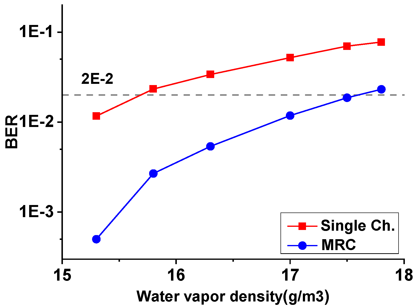
We investigate the bit-error-rate (BER) of 5-GBaud QPSK signals transmitted over a 26 km link under varying climatic conditions, which are attributed to differing water vapor density when near the sea surface. As illustrated in Figure 1, an increase in water vapor density leads to a degradation in the received SNR, thereby causing a deterioration in BER. Additionally, for a given SNR level, the reception performance with dual-branch MRC is superior to that of single-branch reception.
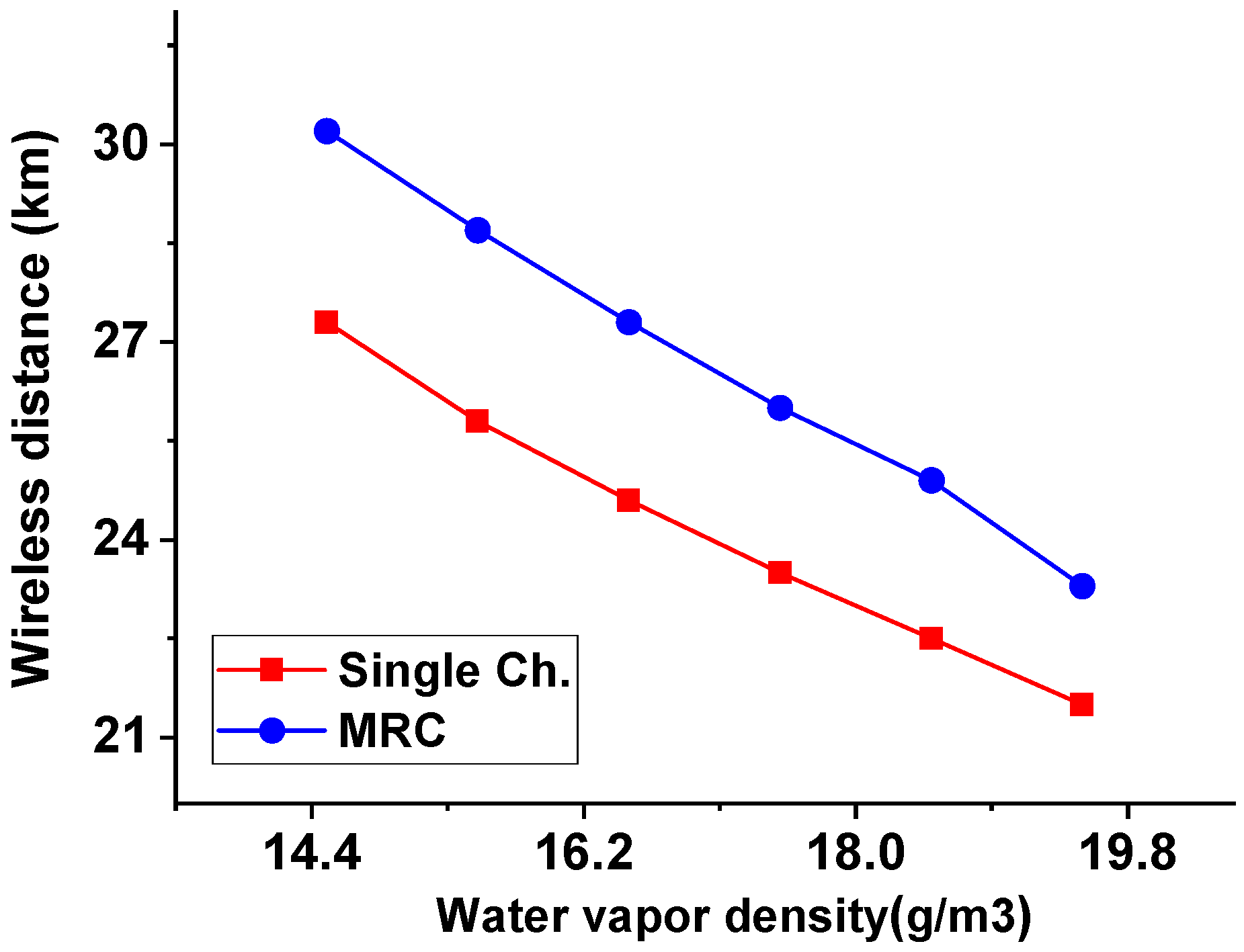
To evaluate the influence of water vapor density on transmission distance, simulations are conducted using 5-Gbaud QPSK signals at a BER threshold of 2 × 10⁻², corresponding to a soft-decision FEC with a 15% overhead. We determine the required SNR at the receiver to maintain the QPSK signal at this specific BER threshold by B E R = 1 2 e r f c ( E b N 0 ) , where the e r f c { } is the complementary error function and E b N 0 represents the bit SNR. Based on this required SNR, we back-calculate the allowable path loss with different water vapor densities and get the maximum achievable wireless transmission distance. It is observed in Figure 2 that the increasing water vapor density leads to higher atmospheric attenuation. Consequently, the achievable wireless distance is reduced to maintain constant received power.

3. Experiment Setup and Deployment

3.1. Transmitter Architecture

Figure 3 shows the transmitter block diagram. A multi-wavelength generation method is used to produce two frequency-locked optical carriers. The ECL linewidth used for the multi-wavelength generation structure is 100 kHz. A 36.75-GHz RF source drives a PM to generate multiple phase-locked subcarriers. The ±1st order sidebands are selected using an optical filter and then amplified by an erbium-doped fiber amplifier (EDFA), producing two optical carriers spaced by 73.5 GHz. One of the optical carriers is fed into an optical IQ modulator and modulated by a 5-Gbaud QPSK signal with a PRBS pattern of length 215–1. The modulated optical carrier is combined with the second carrier, and the two tones beat on a 90 GHz bandwidth photodiode (PD), generating a 73.5 GHz millimeter-wave signal. After the high-power solid-state amplifier, which has an output power of 26 dBm@P1dB and a bandwidth of 15 GHz (from 71 GHz to 86 GHz), the signal is fed into a waveguide and transmitted through a 48 dBi Cassegrain antenna.

3.2. Receiver Architecture

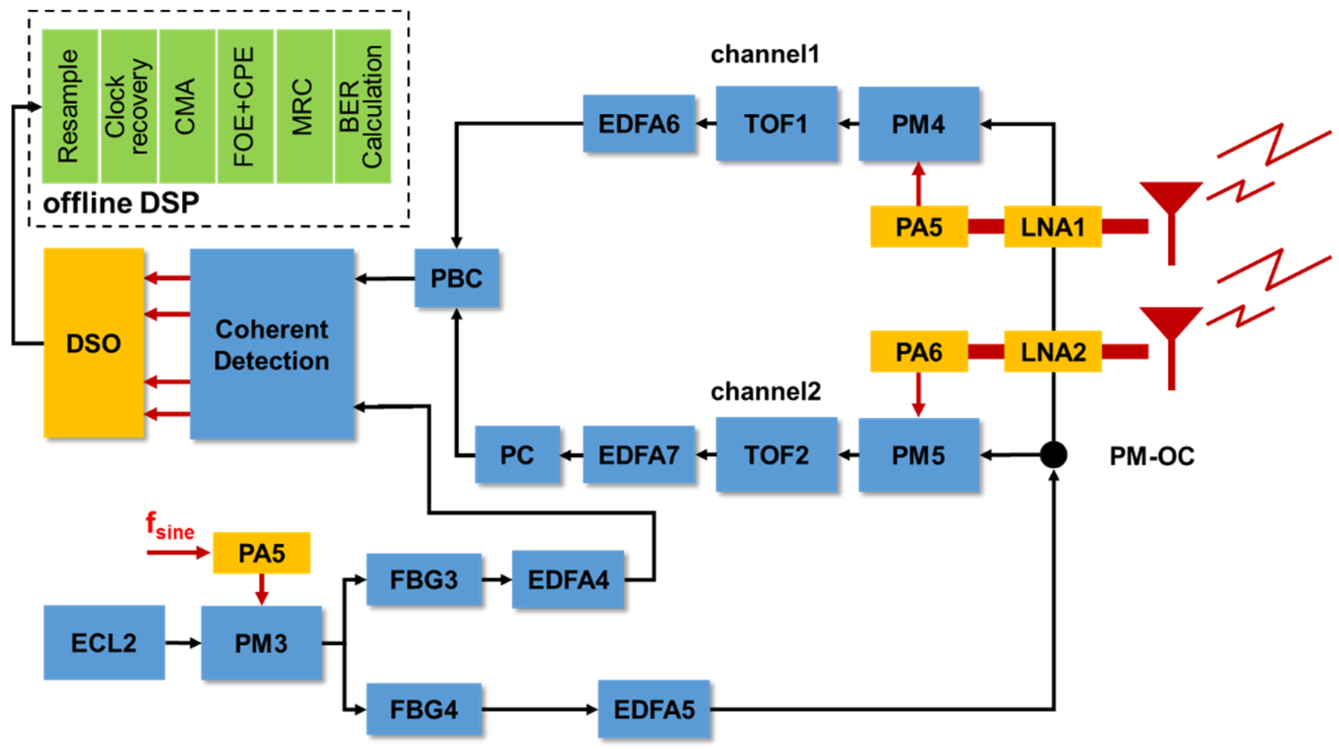
Figure 4 shows the receiver block diagram. Two 48 dBi Cassegrain antennas are used to receive the millimeter-wave signal. After the low-noise amplifier (LNA) with 23 dBi gain and the power amplifier, which is the same as that at the transmitter, the RF signal in each channel drives a 65 GHz bandwidth electro-optic phase modulator, modulating the RF signal onto an optical carrier. In channel 2, the modulated optical signal is filtered, amplified, and then polarization-adjusted to be orthogonal to channel 1. A polarization beam combiner merges the two signals, which then enter a coherent optical receiver. A high-speed oscilloscope samples the four baseband outputs, followed by digital signal processing including resampling, clock recovery, equalization, frequency-offset estimation, and phase-noise compensation. Finally, MRC is applied before the BER measurement.

3.3. Experimental Scenario

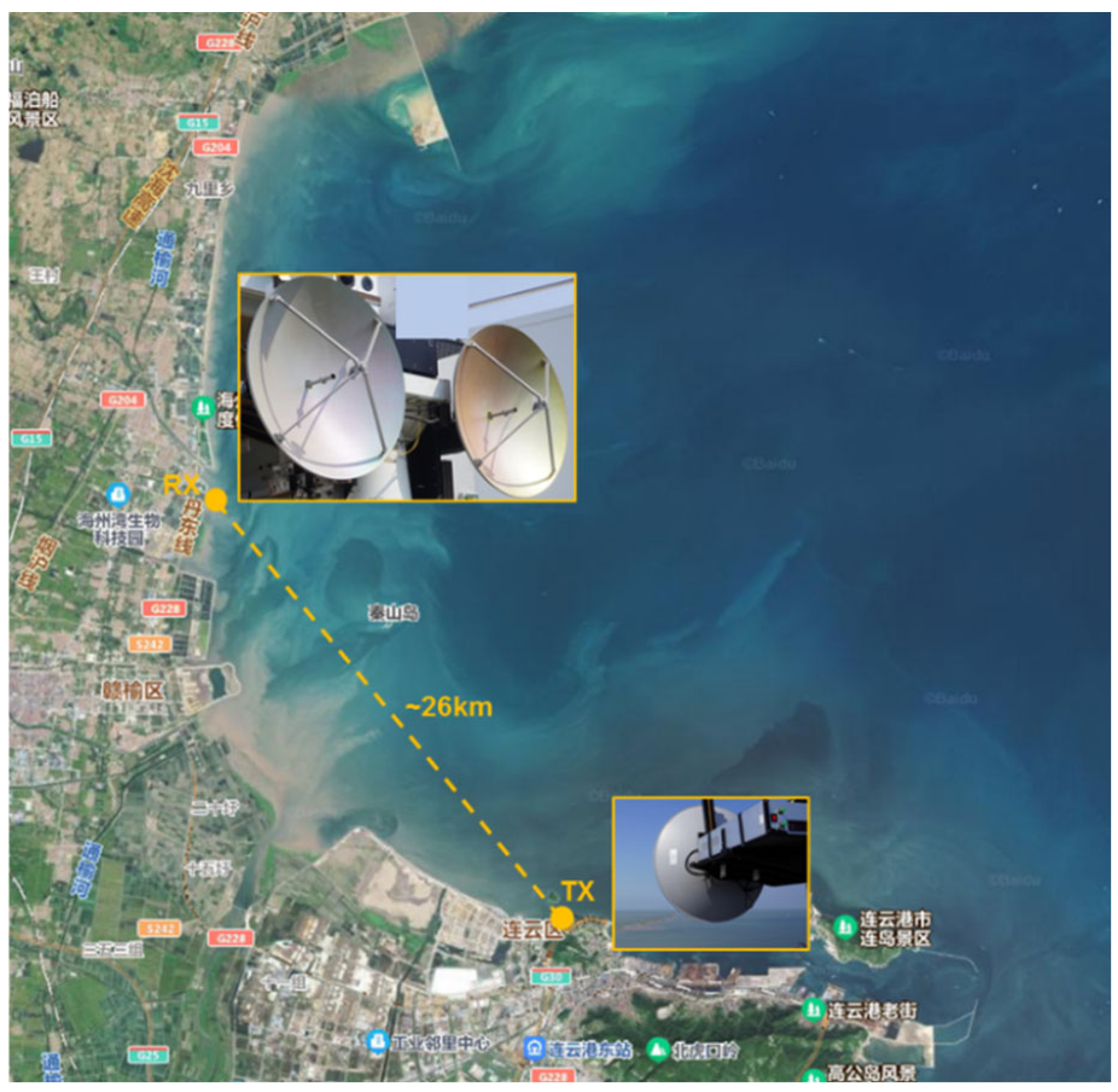
The transmitter is deployed on a seaside tower rooftop approximately 30 m above sea level. The receiver is positioned on a fixed platform about 26 km away. Figure 5 illustrates the experimental scenario of the near-sea-surface transmission setup located in the coastal area of Lianyungang, Jiangsu Province. Initial alignment is achieved using GPS coordinates, followed by fine alignment using received signal strength. Due to the lack of precise measuring instruments, based on the weather on the day of the experiment and the testing time, the temperature, air pressure, and water vapor concentration are 16 °C, 102.9 kpa, and 13.5 g/m3, respectively.

4. Experimental Results and Discussion

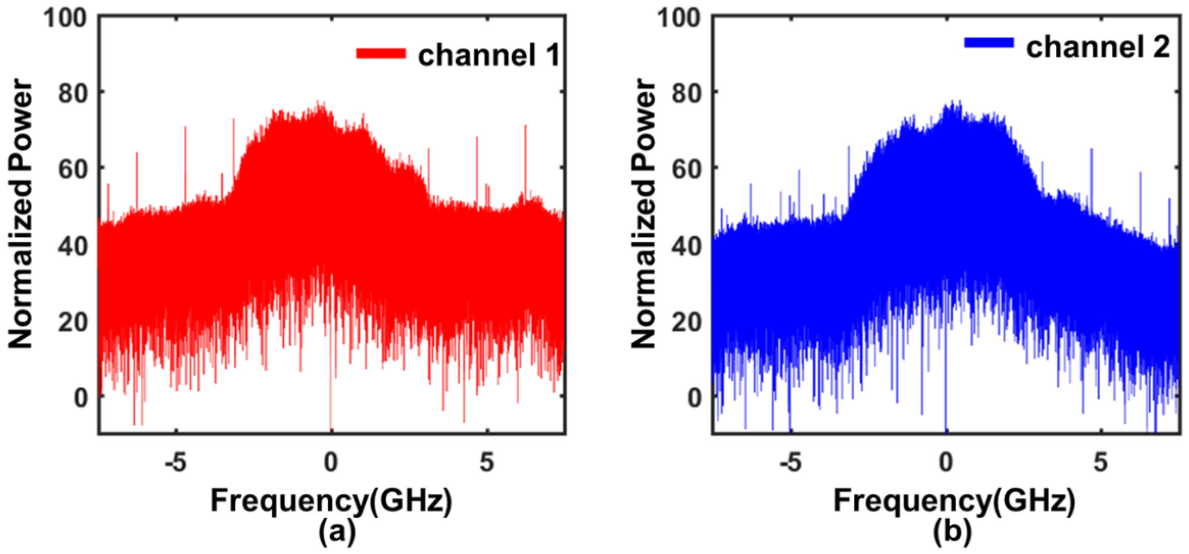
We first measure the electrical spectra of the two received signals after photonic down-conversion and coherent detection, as shown in Figure 6. Although both channels receive the same 5-Gbaud QPSK E-band signal, their spectral amplitudes exhibit observable differences across the 5-GHz bandwidth. These discrepancies may originate from two primary factors: the different broadband frequency responses of the antennas, LNAs, PAs, PMs, PDs, and other electronic and optical components in each channel, and the distinct sea-surface-induced multipath characteristics experienced by the two antennas. Detailed analysis and further investigation into the specific contributions of these factors will be conducted in our future research. At 73.5 GHz (λ ≈ 4 mm), the spacing between the two receive antennas is 85 cm, which corresponds to more than 200 wavelengths, resulting in different multipath fading patterns at each antenna. These observations confirm the necessity and effectiveness of maximal ratio combining at the receiver. The individual digital signal processing (DSP) processing—resampling, CMA equalization, carrier recovery, and phase-noise compensation—is conducted. For BER evaluation, the optical power entering the PMs is gradually reduced by adding an optical attenuator after EDFA5 to emulate increasing transmission distance and corresponding path loss.
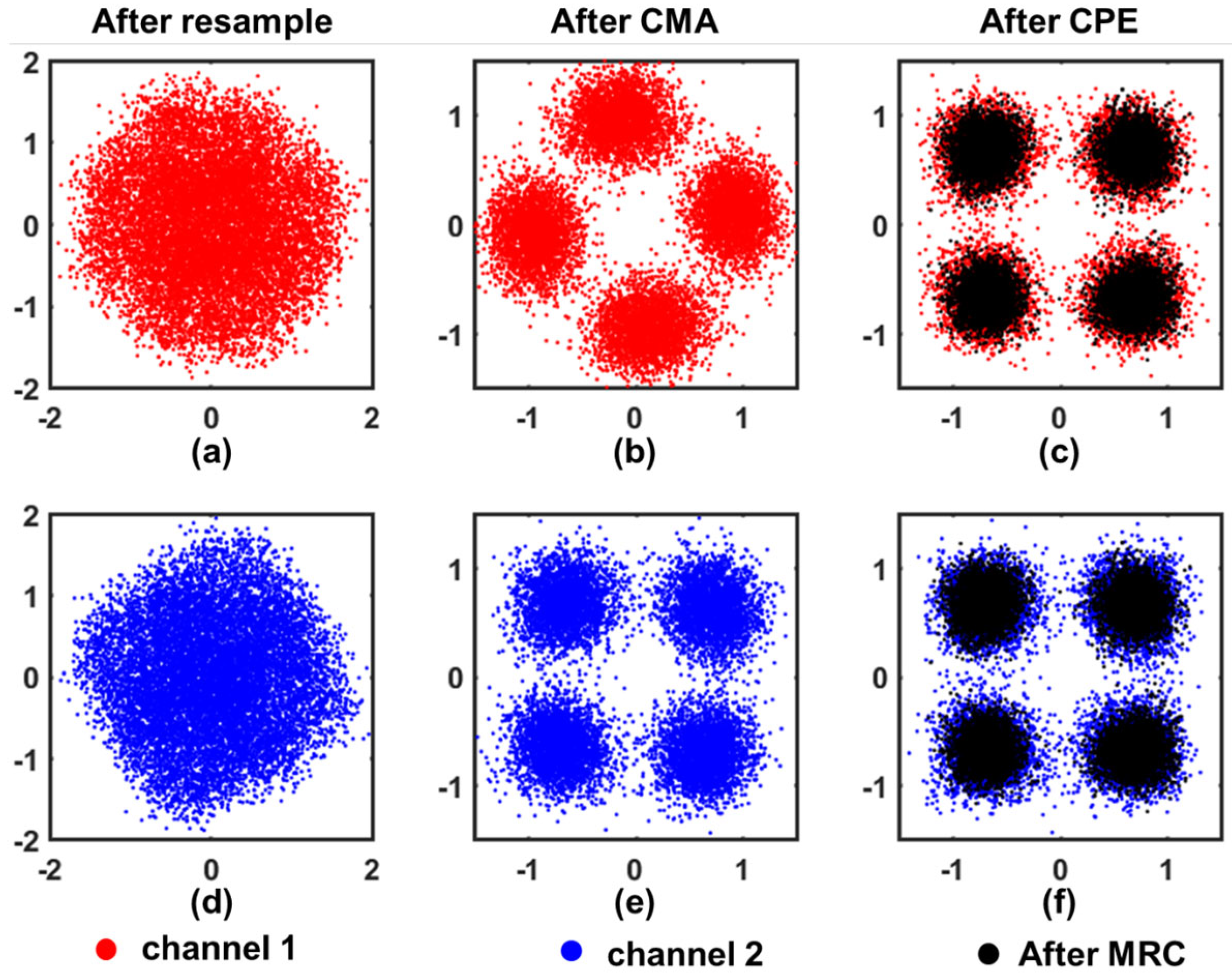
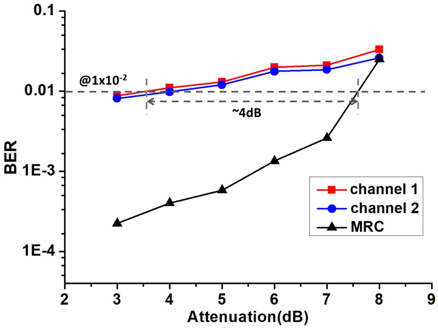
The constellation diagrams of the two channels are shown in Figure 7 with 7 dB optical power attenuation after EDFA 5, and the BER of channel 1 and channel 2 is 2.1 × 10⁻² and 1.9 × 10⁻², respectively. After applying MRC, the constellation points become significantly more concentrated and the BER is reduced to 2.6 × 10⁻³, indicating improved SNR. Figure 8 presents the BER performance after 26 km transmission. At the target BER of 1 × 10⁻², MRC achieves about 4 dB improvement. From the received electrical spectra of the two channels, some differences can be observed; however, the BER performance is found to be comparable, as shown in Figure 8. Therefore, when performing MRC processing, the weight differences between the two channels are not significant.

5. Conclusions

Near-sea-surface humidity and sea-wave-induced multipath severely degrade E-band millimeter-wave transmission. This work proposes a photonic-assisted 1 × 2 MIMO system for E-band long-distance maritime communication. A 26 km near-sea-surface experiment transmitting a 73.5-GHz 5-Gbaud QPSK signal demonstrates that spatial diversity combined with MRC yields about 4 dB performance improvement, which confirms the effectiveness of the proposed system for enabling high-capacity long-range maritime millimeter-wave communication.

Author Contributions

Conceptualization, S.W. and L.T.; Experiment, T.C., Q.L. and R.L. All authors have read and agreed to the published version of the manuscript.

Funding

This research received no external funding.

Data Availability Statement

The original contributions presented in this study are included in the article. Further inquiries can be directed to the corresponding author.

Conflicts of Interest

The authors declare no conflicts of interest.

References

  1. ElMossallamy, M.A.; Zhang, H.; Song, L.; Seddik, K.G.; Han, Z.; Li, G.Y. Reconfigurable Intelligent Surfaces for Wireless Communications: Principles, Challenges, and Opportunities. IEEE Trans. Cogn. Commun. Netw. 2020, 6, 990–1002. [Google Scholar] [CrossRef]
  2. Song, H.-J.; Nagatsuma, T. Present and Future of Terahertz Communications. IEEE Trans. Terahertz Sci. Technol. 2011, 1, 256–263. [Google Scholar] [CrossRef]
  3. Brown, K.; Brown, A.; Feenstra, T.; Gritters, D.; Ko, E.; O’Connor, S.; Sotelo, M.; Raytheon. Long-Range Wireless Link with Fiber-Equivalent Data Rate. In Proceedings of the 2017 IEEE MTT-S International Microwave Symposium (IMS), Honololu, HI, USA, 4–9 June 2017; pp. 809–811. [Google Scholar]
  4. Ping, D.; Lu, Q.; Zhao, J.; Tao, L.; Dong, B.; Liu, Y.; He, S.; Li, R.; Shi, J.; Chi, N.; et al. Full-Photonics up- and Downconversions for W-Band 16-QAM Signal Wireless Delivery over 30.4 Km with Advanced Equalizations. Opt. Lett. 2025, 50, 4314. [Google Scholar] [CrossRef] [PubMed]
  5. Bluemm, C.; Schaedler, M.; Kuschnerov, M.; Pittala, F.; Xie, C. Single Carrier vs. OFDM for Coherent 600Gb/s Data Centre Interconnects with Nonlinear Equalization. In Proceedings of the 2019 Optical Fiber Communications Conference and Exhibition (OFC), San Diego, CA, USA, 3–7 March 2019; pp. 1–3. [Google Scholar]
  6. Ping, D.; Liu, Y.; Dong, B.; Chen, L.; Wang, C.; Zhao, J.; Shi, J.; Shen, C.; Chi, N.; Zhang, J. Experimental Demonstration of a Photonics-Assisted Dual-Hop Radio-over-Fiber System for Routing and Relaying W-Band MMW Signals. Opt. Express 2025, 33, 53563. [Google Scholar] [CrossRef] [PubMed]
  7. Harter, T.; Muehlbrandt, S.; Ummethala, S.; Schmid, A.; Nellen, S.; Hahn, L.; Freude, W.; Koos, C. Silicon–Plasmonic Integrated Circuits for Terahertz Signal Generation and Coherent Detection. Nat. Photonics 2018, 12, 625–633. [Google Scholar] [CrossRef]
  8. Chen, H.; Sarieddeen, H.; Ballal, T.; Wymeersch, H.; Alouini, M.-S.; Al-Naffouri, T.Y. A Tutorial on Terahertz-Band Localization for 6G Communication Systems. IEEE Commun. Surv. Tutor. 2022, 24, 1780–1815. [Google Scholar] [CrossRef]
  9. Harati, P.; Rosello, E.; Dan, I.; Bammidi, E.R.; Eisenbeis, J.; Tessmann, A.; Schwantuschke, D.; Henneberger, R.; Kallfass, I. E-Band Downlink Wireless Data Transmission for Future Satellite Communication. In Proceedings of the 2017 Topical Workshop on Internet of Space (TWIOS), Phoenix, AZ, USA, 15–18 January 2017; pp. 1–4. [Google Scholar]
  10. Chowdhury, M.Z.; Shahjalal, M.; Ahmed, S.; Jang, Y.M. 6G Wireless Communication Systems: Applications, Requirements, Technologies, Challenges, and Research Directions. IEEE Open J. Commun. Soc. 2020, 1, 957–975. [Google Scholar] [CrossRef]
  11. Zhang, Q.; Yu, J.; Zhao, X.; Wang, M.; Lu, X.; Chen, J.; Jiang, L.; Li, Y.; Chen, Y.; Zhou, Y.; et al. 18 Gbps D-Band Wireless Signal Transmission over 30.2 km Land and Sea Surface Based on Photonics Aided Technology. Sci. China Technol. Sci. 2025, 68, 2280901. [Google Scholar] [CrossRef]
  12. Yu, J.; Wang, Y.; Ding, J.; Zhang, J.; Li, W.; Wang, F.; Wang, K.; Tan, Y.; Zhu, M.; Cai, Y.; et al. Broadband Photon-Assisted Terahertz Communication and Sensing. J. Light. Technol. 2023, 41, 3332–3349. [Google Scholar] [CrossRef]
  13. Li, W.; Yu, J.; Zhu, B.; Wang, F.; Ding, J.; Zhang, J.; Yu, J. Photonic Terahertz Wireless Communication: Towards the Goal of High-Speed Kilometer-Level Transmission. J. Light. Technol. 2024, 42, 1159–1172. [Google Scholar] [CrossRef]
  14. Li, L.; Long, T.; Yang, X.; Zhang, Z.; Wang, L.; Wang, J.; Wang, M.; Lu, J.; Yu, J.; Chen, B. Modified Uni-Travelling-Carrier Photodiodes with 206 GHz Bandwidth and 0.81 A W−1 External Responsivity. Nat. Photon. 2025, 19, 1301–1308. [Google Scholar] [CrossRef]
  15. Yu, J.; Jia, Z.; Yi, L.; Su, Y.; Chang, G.-K.; Wang, T. Optical Millimeter-Wave Generation or Up-Conversion Using External Modulators. IEEE Photon. Technol. Lett. 2006, 18, 265. [Google Scholar]
  16. Zhao, Y.; Jang, J.K.; Beals, G.J.; McNulty, K.J.; Ji, X.; Okawachi, Y.; Lipson, M.; Gaeta, A.L. All-Optical Frequency Division on-Chip Using a Single Laser. Nature 2024, 627, 546–552. [Google Scholar] [CrossRef] [PubMed]
  17. Dong, B.; Liu, Y.; Ping, D.; Zhao, J.; Li, Z.; Li, Y.; Huang, O.; Jia, J.; Shi, J.; Chi, N.; et al. Demonstration of Beyond 100G Fiber–Radio–Fiber Bridge at W-Band Based on Full Photonic Up- and Down-Conversions. In Proceedings of the ECOC 2024; 50th European Conference on Optical Communication, Frankfurt, Germany, 22–26 September 2024; pp. 1200–1203. [Google Scholar]
  18. Ping, D.; Gong, S.; Ding, K.; Zhang, Y.; Yang, Z. A 140GHz Terahertz Amplitude Direct Modulator Based on Schottky Diode. In Proceedings of the 2022 47th International Conference on Infrared, Millimeter and Terahertz Waves (IRMMW-THz), Delft, The Netherlands, 28 August–2 September 2022; pp. 1–2. [Google Scholar]
  19. Tian, Y.; Li, Y.; Dong, B.; Xiong, B.; Zhang, J.; Sun, C.; Hao, Z.; Wang, J.; Wang, L.; Han, Y.; et al. High-Power MUTC Photodiode Module for Photonics-Assisted Beyond 100 Gb/S Wireless Sub-THZ Communications in the F-Band. J. Light. Technol. 2024, 42, 5616–5623. [Google Scholar] [CrossRef]
  20. Li, W.; Yu, J.; Zhu, B.; Zhang, J.; Zhu, M.; Wang, C.; Zhou, W.; Xie, T.; Yu, J.; Zhao, F. Photonics 60 GBaud PDM-16QAM Fiber-Wireless 2 × 2 MIMO Delivery at THz-Band. Chin. Opt. Lett. 2023, 21, 073901. [Google Scholar] [CrossRef]
  21. Zhang, Q.; Yu, J.; Zhang, J.; Ding, J.; Li, W.; Wei, Y.; Wang, K.; Zhou, W. Exploiting Polarization Isolation for High Diversity Gain in a THz MIMO System. Sci. China Inf. Sci. 2025, 68, 220310. [Google Scholar] [CrossRef]
  22. Zhang, Q.; Yu, J.; Zhao, X.; Li, W.; Wei, Y.; Yang, X.; Tan, J.; Zhang, B.; Wang, K.; Zhang, Y.; et al. 4.6-Km D-Band Photonic-Assisted Terahertz Wireless Communication Employing SIMO and MRC Technology. IEEE Trans. Microw. Theory Tech. 2024, 72, 6657–6668. [Google Scholar] [CrossRef]
  23. Ping, D.; Liu, Y.; Zhang, H.; Luo, P.; Dong, B.; Chen, L.; Wei, Y.; Shi, J.; Chi, N.; Zhang, J. 54-Gb/s Photonics-Assisted Routing and Relaying W-Band Millimeter-Wave Signals over 4.3-Kilometer Wireless Distance Transmission. In Proceedings of the 2025 23rd International Conference on Optical Communications and Networks (ICOCN), Zhangjiajie, China, 28–31 July 2025; pp. 1–3. [Google Scholar]
  24. Dong, B.; Jia, J.; Li, Z.; Li, G.; Shi, J.; Wang, H. Photonic-Based Flexible Integrated Sensing and Communication with Multiple Targets Detection Capability for W -Band Fiber-Wireless Network. IEEE Trans. Microw. Theory Tech. 2024, 72, 4878–4891. [Google Scholar] [CrossRef]
  25. Liu, Y.; Tao, L.; Dong, B.; Ping, D.; Zhao, J.; He, S.; Lu, Q.; Cheng, T.; Li, Y.; Li, R.; et al. Long-Distance Field Trial of E/W-Band Signal Wireless Delivery Based on Full Photonic Up- and Down-Conversions. J. Light. Technol. 2024, 43, 1794–1805. [Google Scholar] [CrossRef]
  26. Nopchinda, D.; Zhou, Z.; Liu, Z.; Darwazeh, I. Experimental Demonstration of Multiband Comb-Enabled Mm-Wave Transmission. IEEE Microw. Wirel. Technol. Lett. 2023, 33, 919–922. [Google Scholar] [CrossRef]
  27. International Telecommunications Union. Attenuation by Atmospheric Gases and Related Effects, Rec. ITU-R, P.67613; International Telecommunications Union: Geneva, Switzerland, 2022. [Google Scholar]
Figure 1. BER versus different water vapor densities of 5-GBaud QPSK w/wo MRC.
Photonics 13 00112 g001
Figure 2. Wireless distances versus different water vapor densities of 5-GBaud QPSK w/wo MRC.
Photonics 13 00112 g002
Figure 3. Transmitter schematic diagram of the E-band millimeter-wave 1 × 2 MIMO near-sea-surface long-distance transmission system. ECL: external cavity laser; Optical IQ Mod.: optical IQ modulator; PM: phase modulator; EDFA: erbium-doped fiber amplifier; PM-OC: polarization-maintaining optical coupler; TWT PA: traveling-wave tube power amplifier; PD: photodetector; LNA: low-noise amplifier; PA: power amplifier; FBG: fiber Bragg grating.
Photonics 13 00112 g003
Figure 4. Receiver schematic diagram of the E-band millimeter-wave 1 × 2 MIMO near-sea-surface long-distance transmission system. ECL: external cavity laser; TOF: tunable optical filter; PM: phase modulator; EDFA: erbium-doped fiber amplifier; PD: photodetector; LNA: low-noise amplifier; PA: power amplifier; FBG: fiber Bragg grating; PC: polarization controller; PBC: polarization beam combiner.
Photonics 13 00112 g004
Figure 5. Experimental scenario of the near-sea-surface transmission setup in the coastal area of Lianyungang, Jiangsu Province.
Photonics 13 00112 g005
Figure 6. Electrical spectra of the two received signals after photonic down-conversion and coherent detection. (a) channel 1; (b) channel 2.
Photonics 13 00112 g006
Figure 7. Constellation diagrams of the received 5-Gbaud QPSK signals for channel 1 and channel 2. Channel 1: (a) after down-sampling, (b) after CMA equalization, (c) after phase-noise compensation (red) and after MRC (black). Channel 2: (d) after down-sampling, (e) after CMA equalization, (f) after phase-noise compensation (blue) and after MRC (black).
Photonics 13 00112 g007
Figure 8. BER performance of the 5-Gbaud QPSK signal after 26 km near-sea-surface transmission with dual-channel reception and MRC processing.
Photonics 13 00112 g008
Disclaimer/Publisher’s Note: The statements, opinions and data contained in all publications are solely those of the individual author(s) and contributor(s) and not of MDPI and/or the editor(s). MDPI and/or the editor(s) disclaim responsibility for any injury to people or property resulting from any ideas, methods, instructions or products referred to in the content.