Article

A Transformer-Based Approach to Facilitate Inverse Design of Achromatic Metasurfaces

1
College of Advanced Interdisciplinary Studies, National University of Defense Technology, Changsha 410073, China
2
Nanhu Laser Laboratory, National University of Defense Technology, Changsha 410073, China
3
Hunan Provincial Key Laboratory of High Energy Laser Technology, National University of Defense Technology, Changsha 410073, China
*
Authors to whom correspondence should be addressed.
Photonics 2025, 12(9), 913; https://doi.org/10.3390/photonics12090913
Submission received: 23 August 2025 / Revised: 6 September 2025 / Accepted: 9 September 2025 / Published: 11 September 2025
(This article belongs to the Special Issue Optical Metasurfaces: Applications and Trends)

Abstract

Accurate and efficient prediction of the spectral responses of metasurface unit cells is key to intelligent metasurface design. Here, we propose a Shape-integrated Dual-Spectrum-aware transformer (SiDSaT) for forward prediction of metasurface responses. Trained on a large-scale simulation dataset, SiDSaT achieves a phase mean absolute error (MAE) below 0.05 across both cylindrical and cuboidal unit cells, demonstrating strong prediction accuracy and generalization. We further embedded SiDSaT into an inverse design framework and applied it to the design of single-wavelength and broadband achromatic metalenses. Results of focusing performance and dispersion control confirm the effectiveness and versatility of SiDSaT in supporting the high-precision inverse design of metasurface optical devices. This work offers a scalable and accurate approach for intelligent metasurface design across diverse shape configurations and broadband spectral ranges.

1. Introduction

Metasurfaces are composed of sub-wavelength-scale nanostructures and enable precise control of the phase, amplitude, and polarization of light on a planar platform, thereby supporting the development of multifunctional integrated optical devices such as metalenses, holographic elements, and beam shaping systems [1,2,3,4,5,6,7,8,9,10,11,12,13,14]. Despite their significant potential in micro–nano optics, metasurfaces still face critical challenges under broadband conditions due to inherent dispersion issues. Traditional single-layer metasurfaces based on linear phase compensation can correct chromatic aberration within narrow or moderately wide spectral ranges [15,16]. However, these approaches fundamentally rely on linear approximations of monotonic dispersion, which fail to accurately capture the nonlinear dispersion behaviors of materials and nanostructures. As a result, such mismatch leads to wavefront distortions and degraded focusing performance in ultra-broadband scenarios, thus limiting their applicability in wide-spectrum optical systems [17].
To overcome this limitation, Hu et al. proposed a generalized asymptotic phase compensation strategy [18,19], which introduces tunable phase shifts along the wavelength dimension to asymptotically match the nonlinear structural dispersion. This approach expands the degree of freedom for chromatic aberration correction beyond linear approximations. However, it also significantly increases the design complexity, as it requires establishing high-dimensional mappings between desired phase profiles and structural parameters across multiple wavelengths. While traditional full-wave simulation methods (e.g., finite-difference time-domain, FDTD [10,20,21]) can provide accurate predictions, their iterative optimization process is computationally expensive and time-consuming.
Deep learning techniques have been widely integrated into the design workflow of metastructured devices in recent years to improve the simulation efficiency [22,23,24,25,26,27,28,29,30,31,32,33]. These techniques using deep neural networks (DNNs) can efficiently learn the complex mappings between structural parameters and electromagnetic (EM) responses, enabling millisecond-level forward prediction and accelerating the inverse reasoning process from target spectra to structural configurations. Previous studies have explored architectures such as fully connected networks (FCNs) [19,34,35,36], generative adversarial networks (GANs) [37], bidirectional neural networks (BNNs) [28], and neural tensor networks (NTNs) [23,30,38,39]. However, most of these methods either fail to capture long-range dependencies within spectral sequences or rely on downsampling strategies that overlook critical sharp features in the spectra, thereby compromising prediction accuracy. The transformer architecture has recently gained popularity in photonic tasks due to its powerful sequence modeling capabilities [24,40,41], which allow it to attend to global spectral features and capture long-range correlations more effectively. However, existing transformer-based approaches in this domain typically rely on deeply stacked self-attention layers to reach high accuracy, resulting in very large models and increased computational complexity. At the same time, most current deep learning frameworks do not support training on multiple heterogeneous structural types within a single model, which limits scalability and applicability in multi-shape design tasks.
In this work, we propose a transformer-enhanced deep learning framework for efficient and accurate inverse design of broadband achromatic metasurfaces. First, we designed a lightweight and extensible forward prediction network, Shape-integrated Dual-Spectrum-aware transformer (SiDSaT), for highly accurate prediction of the spectrum. SiDSaT introduces a dual-branch spectral-modeling mechanism that concurrently captures long-range dependencies and resolves sharp spectral features, thereby sustaining high prediction accuracy across wide bandwidths and overcoming the limitations of single-branch models. In addition, the shape-integration module enables a single unified model to be trained on and used for inference across multiple nanostructure geometries, eliminating the need for separate networks for each shape. Unlike prior transformer-based approaches that rely on heavy layer stacking, SiDSaT adopts a shallow, lightweight architecture that markedly reduces parameter count and computational overhead while preserving predictive accuracy. We train and evaluate SiDSaT on extensive FDTD-simulated datasets, confirming precise spectral predictions across broad wavelength ranges and multiple shape categories. We then integrate SiDSaT with a hybrid inverse design algorithm combining Particle Swarm Optimization and a Genetic Algorithm (PSO-GA), demonstrating its feasibility for both single-wavelength designs and broadband asymptotic phase-compensated metalens applications. We expect that SiDSaT can be readily extended to a wider range of practical metasurface design scenarios.

2. Theory and Methodology

To construct a unified inverse design framework for metalenses, we developed a high-precision and lightweight transformer-based forward prediction model, SiDSaT, and integrated it with an evolutionary optimization strategy, PSO-GA, as illustrated in Figure 1.
Figure 1a shows the focusing mechanism of achromatic metalenses realized by modulating the phase of incident wavefronts through a sub-wavelength nanostructure array. Figure 1b depicts the workflow of SiDSaT, which takes the structural parameters and shape type of the unit cell as inputs. After preprocessing, the Shape-integrated module extracts shape-specific features via a gated fusion mechanism. Next, the Dual-Spectrum-aware transformer performs spectral sequence modeling through two parallel branches: the Global Perception transformer (GPT) and the Local Perception transformer (LPT). The network outputs the predicted spectral response through a multi-head output module. Figure 1c illustrates the PSO-GA-based optimization framework, which embeds the pre-trained SiDSaT model to obtain the corresponding predicted phases. The predicted phases are compared with the ideal phases using a loss function that quantifies focusing performance. The result is fed back into the PSO and GA modules to jointly update the structural parameters and reference phase r λ . Through this process, optimal parameters are obtained and validated by FDTD simulations, demonstrating effective focusing and dispersion control.

2.1. Forward Prediction

2.1.1. Architecture of SiDSaT

Figure 2 shows the architecture of the forward prediction network, SiDSaT. It utilizes a combination of inter-fragment cross-attention and intra-fragment self-attention mechanisms to extract a rich set of spectral features. As shown in Figure 2a, the network is composed of four main components: a preprocessing and fully connected layer (FCL) for dimensional expansion, a Shape-integrated module for handling diverse shape types, a Dual-Spectrum-aware transformer for spectral modeling, and an output head for final prediction.
The preprocessing module includes two linear layers, each tailored for a specific shape type. These modules map geometric parameters with differing semantics (e.g., radius and height for cylinders, or side length and height for squares) into a unified vector representation of size D   ×   1 , resolving inconsistencies across shape formats. After normalization and mapping, the unified features are fed into a shared three-layer residual block (FCL), expanding the embedding to a higher-dimensional representation of size T   ×   1 .
Simultaneously, as shown in Figure 2b, the Shape-integrated module encodes the shape type label using a three-layer linear embedding, producing a shape vector of the same dimension T   ×   1 . A gating mechanism then learns soft fusion weights to adaptively combine the shape prior with the geometric features. This flexible fusion strategy maintains the continuity of geometric input while integrating discrete shape information, thereby enhancing the adaptability of the model to multiple shape types. This design allows SiDSaT to be trained on and make predictions for heterogeneous structures using a single model, improving training efficiency and structural generalization compared to traditional approaches requiring separate networks per shape.
The fused features are then passed to the Dual-Spectrum-aware transformer module. The features are first normalized and reshaped into an n   ×   T n segment format. Based on the idea that different heads focus on different spectral segments, we propose a two-stage global–local spectral attention mechanism, comprising a Global Perception transformer (GPT) and a Local Perception transformer (LPT). The GPT uses a cross-attention mechanism to capture long-range dependencies between spectral fragments, while the LPT applies self-attention within each segment to refine local detail modeling.
As illustrated in Figure 2c, the Global Perception transformer operates on the matrix formed by all spectral fragments. Through linear projections, it generates the query (Q), key (K), and value (V) matrices of identical shape n   × T n , which are subsequently reshaped into a multi-head attention format with dimensions h d × n h d × T n , where h d denotes the dimension per attention head and m   = n h d is the total number of heads.
This setup employs a cross-fragment attention mechanism to capture dependencies among different spectral fragments, thereby enabling effective extraction of global spectral features. The attention weights W G ( Q , K ) and the multi-head attention output M G ( Q , K , V ) are computed as follows:
W G Q , K = S o f t m a x Q K h d
M G Q , K , V = W G V
Q = ( Q 1 , Q 2 , . . . , Q m ) T , K = ( K 1 , K 2 , . . . , K m ) T , V = ( V 1 , V 2 , . . . , V m ) T
Here, the attention weights are calculated by performing scaled dot-product between the projected Q and K, followed by a softmax operation. Each query head Q i interacts exclusively with its corresponding key head K i , and the outputs from all heads are concatenated to produce the final multi-head attention result M G ( Q , K , V ) . This mechanism effectively captures the global spectral dependencies, facilitating coarse-level global spectrum modeling.
As shown in Figure 2d, the Local Perception transformer processes each spectral fragment independently. For each fragment, linear projections generate their own Q, K, and V matrices of shape h d × n h d , where h d and m = n h d retain their definitions. This mechanism focuses on capturing intra-fragment (local) spectral relationships.
As described in Equations (4) and (5), the attention weights W L Q , K are computed similarly to the global transformer, but with two key differences: all Q, K, and V come from the same spectral fragment, and a sigmoid activation is applied instead of softmax:
W L = W 1 L , W 2 L , . . . W n L ,   W i L Q , K = S i g m o i d Q i K i h d
M L Q , K , V = W L V , M i L Q i , K i , V i = W i L V i
The attention output M L ( Q , K , V ) is obtained via element-wise (Hadamard) multiplication between the weight matrix W L and the value matrix V . Notably, each W i L is computed using only the corresponding fragment’s own Q i and K i , ensuring strict local context modeling. By aggregating outputs from all attention heads and fragments, the final output is constructed.
This dual-branch module separates global and local spectral modeling. The Global Perception transformer (GPT) performs cross-fragment multi-head attention over the full wavelength grid; because scaled dot-product attention links distant spectral segments, its output is most responsive where the spectrum–wavelength curve exhibits pronounced curvature (i.e., where long-range correlations across segments are strongest). By contrast, the Local Perception transformer (LPT) applies self-attention within each segment and thus acts as a local refiner, emphasizing steep slopes and narrow features that would otherwise be smeared by downsampling. This division of labor provides a physics-aligned representation: GPT targets wavelength regions pivotal for dispersion control, whereas LPT preserves sharp features relevant to fabrication-sensitive spectrum behavior.
After attention, the outputs are reshaped and projected back to the original segment format. A first residual connection is applied, followed by flattening to size T   ×   1 , then passed through a Norm and Feed Forward (NFF) layer and a second residual connection. The resulting attention-enhanced representation is sent to the output head for final spectral prediction.
Since metasurface lens design focuses primarily on phase information, the loss function for SiDSaT uses trigonometric error to mitigate the impact of phase discontinuities (see Equation (6)). The performance of the model is quantitatively evaluated using the mean absolute error (MAE) of phase on the validation set (see Equation (7)).
L S i D S a T = 1 N i = 1,2 , , N [ ( c o s ( P h a s e p r e ) c o s ( P h a s e s i m ) ) 2 + ( s i n ( P h a s e p r e ) s i n ( P h a s e s i m ) ) 2 ]
E S i D S a T = 1 N i = 1,2 , , N P h a s e p r e P h a s e s i m
Here, P h a s e p r e denotes the phase predicted by SiDSaT, while P h a s e s i m represents the reference phase obtained from FDTD simulations.

2.1.2. Dataset Generation

To train and validate the SiDSaT model, we constructed a dataset comprising geometric parameters of metasurface unit cells and their corresponding spectral responses. The target of our metalens design is to achieve efficient focusing and broadband achromatic performance in the near-infrared regime. Titanium dioxide (TiO2) is selected as the structural material due to its high refractive index and low absorption loss, while silicon dioxide (SiO2) serves as the substrate owing to its high transparency and material compatibility, making it a common choice for waveguide-type structures.
The unit cell period is set to 500 nm to satisfy the zero-order diffraction condition within the 800–1600 nm wavelength range, suppress higher-order diffraction, and strike a balance between fabrication resolution and optical performance. The geometric parameters include primary scalar values such as radius (r) and width (d), along with a shape type indicator (e.g., cylindrical or cuboidal).
The spectral responses of each structure are computed using FDTD simulations across 81 discrete wavelength points in the 800–1600 nm range. To eliminate the ambiguity caused by phase wrapping, the corresponding phase responses are encoded using sine and cosine representations.
To ensure balanced sampling during training, we employ stratified splitting based on compound labels formed by grouping geometric parameters and shape types. This approach guarantees fair representation of all unit types in both the training and validation sets.

2.2. Inverse Design

The purpose of inverse design is to iteratively search for optimal nanostructure parameters that yield the desired spectral phase response across a wide wavelength range. To achieve this goal, we integrate the proposed SiDSaT forward prediction network with a hybrid optimization framework that combines Particle Swarm Optimization (PSO) and Genetic Algorithm (GA).
However, in the conducted constraint analysis, the inverse design of metasurfaces is not a purely mathematical optimization problem but is inherently constrained by the physical realizability of the phase profile and its dispersion. In broadband achromatic focusing, the target phase distribution should not only satisfy wavelength-dependent focusing conditions but also remain consistent with the nonlinear phase dispersion of nanostructured meta-units. By rigorously analyzing the compatibility between ideal phase requirements and the dispersion capacity of the meta-unit library, we delineate the feasible design space, which provides the physical foundation for the optimization framework described in the following subsection.

2.2.1. The Principle of Achromatic Metalens

When treating each metasurface unit cell as a vertical waveguide, its phase response can be expressed as follows [42]:
φ m e t a = 2 π λ n e f f
In previous studies, the structural dispersion of unit cells was often assumed to be linear, which neglected the wavelength dependence of the effective refractive index [16]. As shown in Figure 3a, the phase profile of linear dispersion is typically constructed as
φ l i n e a r r , λ = 2 π λ r 2 + f 2 r 0 2 + f 2
where f is the focal length, and r 0 is the radial position at which the wavefront intersects the lens surface.
In achromatic design, when r   <   r 0 , this approach allows approximate linear fitting of the structural dispersion, enabling compensation for chromatic aberration within a limited bandwidth. However, under one-dimensional effective medium theory, the effective refractive index generally varies with wavelength. As such, the linear compensation method becomes insufficient for broadband control of focusing dispersion. Moreover, it is nearly impossible to design a broadband focal dispersion control lens (i.e., with wavelength-dependent focal length f λ ) using this approach.
To better align with the nonlinear structural dispersion of metasurface units and enable arbitrary dispersion engineering across ultra-broadbands, Hu et al. introduced the asymptotic phase compensation method [18]:
φ a s y m p t r , λ = 2 π λ r 2 + f 2 r λ 2 + f 2
As illustrated in Figure 3b, this method introduces a wavelength-dependent shift variable r λ . Thus, the local phase relations can be freely constructed to asymptotically match nonlinear dispersion characteristics, enabling arbitrary dispersion control across broadband spectra.
Notably, Equation (10) can be decomposed as
φ a s y m p t r , λ = 2 π λ r 2 + f 2 f + φ s h i f t λ
where
φ s h i f t λ = 2 π λ r λ 2 + f 2 f
Here, φ s h i f t λ represents a phase shift term dependent only on the wavelength.

2.2.2. Constraint Analysis for Metalens Design

In practice, the phase response of each unit cell is constrained within a finite range, which directly impacts whether a target phase profile can be realized across the entire wavelength band. Thus, to ensure broadband feasibility of the desired phase distribution, the relationship between the achievable phase dispersion of the structure library and the required bandwidth must be rigorously evaluated.
For Equation (10), the required phase difference between the lens center and edge at a fixed wavelength (independent of φ s h i f t ) is
φ a s y m p t λ = φ a s y m p t 0 , λ φ a s y m p t R m a x , λ = 2 π λ R m a x 2 + f 2 f
Therefore, for two wavelengths λ 1 > λ 2 , the phase difference gap is
φ 0 λ 1 , λ 2 = φ a s y m p t λ 2 φ a s y m p t λ 1 = 2 π 1 λ 2 1 λ 1 R m a x 2 + f 2 f
To ensure the unit cell library covers the required phase dispersion range between two wavelengths, the following condition must hold (see Figure 3c):
φ a s y m p t R m a x , λ 2 φ a s y m p t R m a x , λ 1 φ u n i t m i n λ 1 , λ 2 φ u n i t m a x λ 1 , λ 2 φ a s y m p t 0 , λ 2 φ a s y m p t 0 , λ 1
Here, φ u n i t m i n and φ u n i t m a x denote the minimum and maximum achievable phase variation in the meta-units between two wavelengths.
Summing both inequalities, we obtain
φ u n i t m a x λ 1 , λ 2 φ u n i t m i n λ 1 , λ 2 φ 0 λ 1 , λ 2
Rewriting the right-hand side as a bandwidth-dependent parameter χ , this yields
R m a x 2 + f 2 f φ u n i t m a x λ 1 , λ 2 φ u n i t m i n λ 1 , λ 2 2 π 1 λ 2 1 λ 1 = χ
Thus, to ensure sufficient phase coverage across all wavelength pairs in the design bandwidth, the constraint becomes
R m a x 2 + f 2 f χ m i n
This leads to the following constraints on focal length and lens radius:
0 < f   , 0 < R m a x χ m i n R m a x 2 χ m i n 2 2 χ m i n   f , R m a x > χ m i n
And similarly for numerical aperture (NA):
0 < N A < 1   , 0 <   R m a x χ m i n 0 < N A < 2 χ m i n R m a x 2 + χ m i n 2   , R m a x > χ m i n
These derivations reveal that large-scale, high-NA, or broadband metasurfaces require a unit cell library with a sufficiently wide dispersion range χ . If the library lacks adequate coverage (e.g., with a single-type structure), a trade-off between lens size, NA, and bandwidth becomes inevitable.
Since the variable r λ is wavelength-dependent and unconstrained, its range is difficult to define. However, the associated phase shift φ s h i f t λ remains bounded between π and π . Therefore, we introduce a wavelength-specific compensation term:
φ s h i f t λ = C λ ,
and directly optimize it in the inverse design process.

2.2.3. PSO-GA-Based Inverse Design Strategy

The primary objective of metalens inverse design is to minimize the discrepancy between the ideal phase profile and the actual phase wavefront produced by the structural configuration at each wavelength. In this study, we adopt a phase-matching loss based on sine and cosine representations, consistent with outputs of the forward model, to avoid ambiguities caused by phase wrapping. The triangle-based error function ε t r i is defined as
ε t r i = i = 1 n λ r = 1 r m a x ( s i n ( Δ φ i d e a l ) s i n ( Δ φ u n i t ) ) 2 + ( c o s ( Δ φ i d e a l ) c o s ( Δ φ u n i t ) ) 2 )
To solve the inverse design problem, we employ a hybrid optimization strategy that integrates Particle Swarm Optimization (PSO) and Genetic Algorithm (GA), referred to as PSO-GA, as shown in Figure 4. This approach combines the rapid local search ability of PSO with the global exploration capability of GA. The inclusion of crossover and mutation operations helps prevent PSO from falling into local minima, while the swarm’s dynamic update mechanism accelerates the convergence of GA.
The PSO component performs local search in the parameter space through iterative updates of particle velocity and position, defined as
v i t + 1 = w v i t + c 1 r 1 ( p b e s t i t x i t ) + c 2 r 2 ( g b e s t t x i t ) ) x i t + 1 = x i t + v i t + 1
where r 1 , r 2 U 0,1 are random coefficients, p b e s t i is the best-known position of particle i , and g b e s t is the global best position found so far. The velocity is constrained by a maximum threshold v m a x = 0.1 d m a x d m i n to prevent divergence. The inertia weight w regulates memory of past velocities, while cognitive ( c 1 ) and social ( c 2 ) coefficients control convergence toward individual and global optima, respectively.
The GA component enhances population diversity via tournament selection, uniform crossover, and Gaussian mutation. GA is periodically invoked to intervene in the PSO process, facilitating population migration and promoting bidirectional information flow between modules.
During the optimization, the pre-trained SiDSaT forward model is utilized as a physics-aware surrogate to predict the phase response of candidate unit structures. Since the objective function is defined by the trigonometric phase error ε t r i , the model’s outputs (i.e., predicted sine and cosine of phase) can be directly used in the evaluation without requiring explicit phase reconstruction, thereby avoiding phase discontinuity artifacts.

3. Results and Discussion

3.1. Evaluation of SiDSaT

3.1.1. Predicted Results of Our Dataset

To evaluate the prediction accuracy of the fully trained SiDSaT model, we tested it on all samples in the dataset, as well as on additional samples randomly selected from the parameter space that were not included in the training set. The predicted and simulated spectral responses are compared, and their discrepancies are quantified using the mean absolute error (MAE).
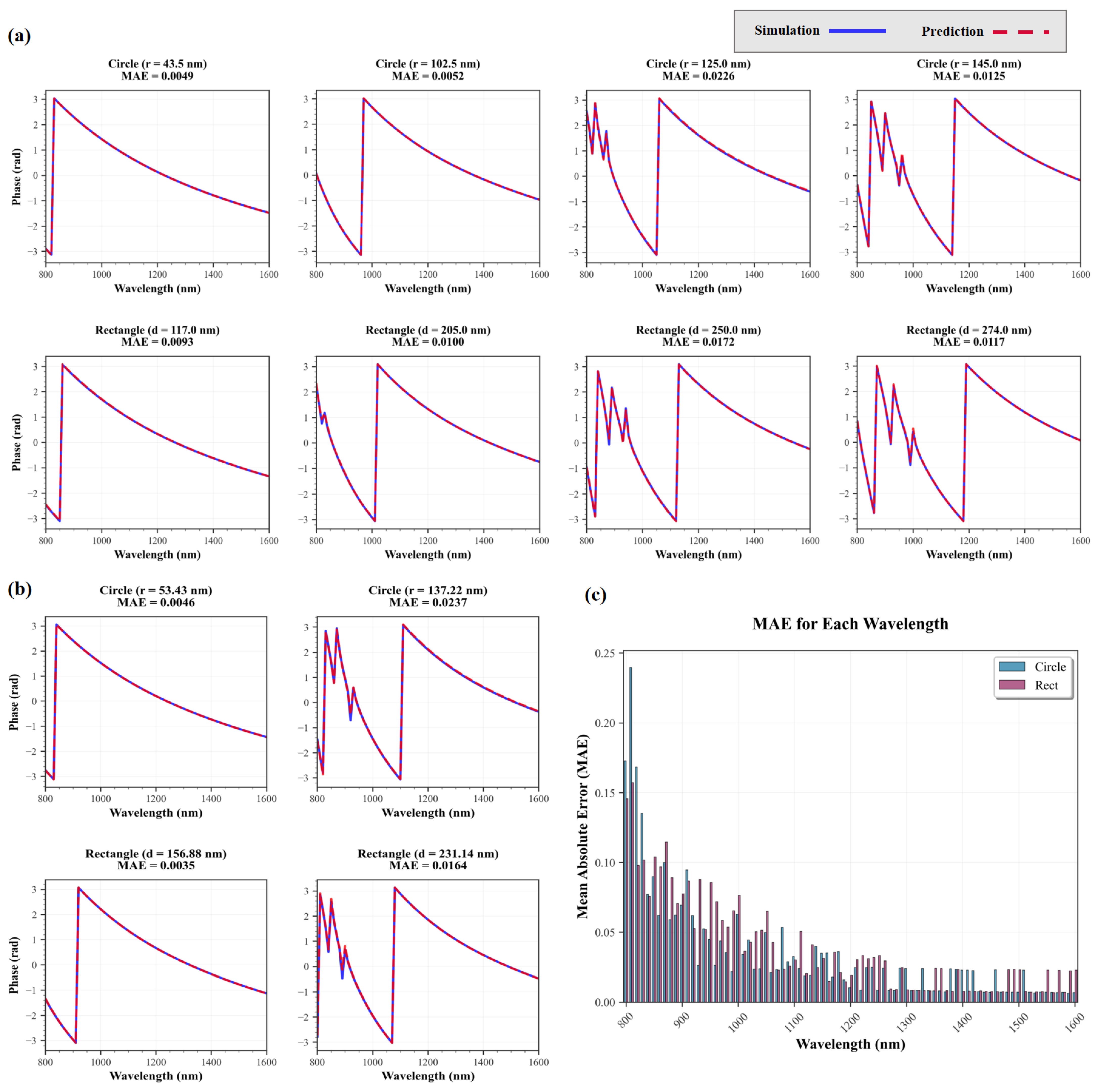
Figure 5a,b show examples of prediction results for samples within the dataset and the predictions for unseen samples outside the dataset, respectively. Figure 5c presents the MAE of predicted phase values at each sampled wavelength from 800 nm to 1600 nm across the entire dataset. The overall MAEs for cylindrical and rectangular metasurface units are 0.0473 and 0.0446, respectively.
The proposed SiDSaT model demonstrates excellent predictive capability across varying geometric parameters (e.g., radius, width) and structural shapes (circular and rectangular). Even for unseen samples, the predicted phase spectra remain highly consistent with FDTD simulation results across the entire wavelength range, showing near-perfect overlap in the long-wavelength region. For structures with strong dispersive behavior, including those exhibiting phase discontinuities, SiDSaT still accurately captures the spectral trends, with only minor deviations near the spectral boundaries.
The MAE statistics for each wavelength point in Figure 5c reveal that prediction errors are generally low throughout the spectrum. Higher errors are mainly concentrated in the short-wavelength region (800–950 nm), which may be attributed to stronger material dispersion and rapid changes in phase response. As the wavelength increases, the MAE quickly decreases and stabilizes, indicating better generalization performance in the mid-to-long wavelength range.
In summary, SiDSaT achieves low phase prediction error across the entire wavelength range for metasurface units with various shapes and geometries. Additionally, validation on more complex and heterogeneous datasets is provided in Appendix A.1 (Figure A1) and Appendix A.2 (Figure A2). These results verify the model’s capability in learning complex high-dimensional structural relationships and accurately modeling spectral responses, providing a robust and reliable foundation for subsequent inverse design.

3.1.2. Ablation Study

To systematically evaluate the contribution of each key module in the proposed SiDSaT model to the prediction performance, we conducted ablation studies by comparing the full SiDSaT architecture against several variant models with specific components removed, as illustrated in Figure 6. Specifically, we performed ablation by individually removing the following modules: the Shape-integrated module (denoted as without Si), the Global Perception transformer (without GPT), the Local Perception transformer (without LPT), and the entire dual-transformer structure (without transformer). In addition, we included a baseline FCN model, which lacks both shape-awareness and attention mechanisms, for comparative analysis.
From Figure 6, we observe that the complete SiDSaT model (red curve) consistently achieves the lowest validation loss throughout the training process, demonstrating faster convergence and lower variance. This highlights its superior capability in learning spectral responses. In contrast, the baseline FCN (sky blue curve) exhibits significantly higher error and oscillation across the entire training trajectory, indicating that traditional fully connected architectures struggle to effectively model spectral sequences.
Notably, the inset in the upper-right corner of Figure 6 shows a magnified view of the final training stage (Epochs 3000–4000). The full model not only attains the lowest final validation loss but also maintains the smallest fluctuation range, demonstrating excellent long-term stability and robustness. Among the variant models, removing either transformer sub-module (GPT or LPT) leads to noticeable performance degradation, which confirms that global and local spectral-modeling strategies are complementary: GPT captures cross-fragment dependencies, while LPT characterizes intra-fragment variations. Together, they enhance both modeling depth and precision.
Eliminating the Shape-integrated module also causes a significant increase in prediction error, underscoring the importance of structural shape information in accurate spectral response modeling. Moreover, the model without any transformer components exhibits saturated performance in later training stages, suggesting the essential role of attention mechanisms in modeling high-dimensional structure-to-spectrum mappings.
In summary, the ablation study clearly demonstrates that each module in SiDSaT plays a critical role in performance enhancement. The full architecture surpasses all simplified variants in terms of accuracy, convergence speed, and training stability, validating the effectiveness of its overall design.

3.2. Evaluation of PSO-GA

3.2.1. Application in Single-Wavelength Metalenses

To validate the effectiveness of our SiDSaT-based inverse design framework, we performed single-wavelength metalens design experiments at key wavelengths: 850 nm, 1064 nm, and 1310 nm, corresponding to standard bands used in biological imaging, optical communication, and LiDAR systems. These wavelengths were selected due to their widespread practical applications and distinct dispersion characteristics in the near-infrared range.
The proposed metalens is constructed from a combination of multiple structural geometries. The lens diameters and focal lengths were carefully chosen to balance diffraction performance and fabrication feasibility. Specifically, lenses with 60 μm or 40 μm diameters and 50–200 μm focal lengths were used to satisfy zero-order diffraction conditions while allowing sub-wavelength resolution under fabrication constraints.
The focusing performance of the four designs is illustrated in Figure 7a–d, showing both the electric field intensity distribution and the corresponding focal plane profiles. Table 1 summarizes the key metrics, including designed and actual focal length, numerical aperture (NA), full width at half maximum (FWHM), depth of focus (DOF), transmittance η t r a n s , focusing efficiency η f o c u s | t r a n s , and focus ratio.
Notably, the focus ratio is defined as
F o c u s   R a t i o = F W H M a c t u a l F W H M d i f f r a c t i o n l i m i t e d = F W H M a c t u a l 0.514 λ N A
This metric quantifies the closeness of the focal spot to the diffraction limit, where a value close to 1 indicates near-diffraction-limited focusing. We also use two efficiency metrics for subsequent analyses: transmittance η t r a n s , the ratio of power transmitted through the metalens aperture to the incident power, and focusing efficiency η f o c u s | t r a n s , the ratio of power within FWHM at f a c t u a l to transmitted power.
As shown in Table 1, the achieved focal lengths closely match the targets (e.g., 199.2 µm vs. 200 µm; <0.5% error across cases). The NAs span 0.15–0.37, with measured focal spot FWHM values of 1.64–3.06 µm. All four metalenses achieve focus ratios in the range of 1.04–1.21, indicating near-diffraction-limited focusing and high-fidelity phase reconstruction. The efficiency metrics η t r a n s and η f o c u s | t r a n s are uniformly high across cases, while the wavefront quality is further supported by Strehl ratios of ~0.63–0.91. The depth of focus (DOF) ranges from ~7.5 to 35.8 µm, providing axial tolerance to minor defocus and fabrication variations.
Collectively, these metrics indicate that the SiDSaT-PSO-GA framework yields high-efficiency, near-diffraction-limited single-band metalenses with tightly focused beams. The close agreement between actual and target focal lengths, along with narrow focal spot sizes, further corroborates the accuracy of the SiDSaT forward model in forward prediction and the reliability of the PSO-GA optimizer in converging to physically valid geometries that reconstruct the intended phase profile.

3.2.2. Application in Broadband Metalenses

To verify the applicability of the proposed inverse design framework in broadband scenarios, we further designed an achromatic metalens capable of operating across the 1000–1400 nm spectral range. The proposed metalens is also constructed from a combination of multiple structural geometries. The design objective was to maintain an approximately constant focal length across the working bandwidth while minimizing chromatic focal shift and preserving stable focusing performance. The metalens diameter was set to 60 μm with a target focal length of 400 μm, meeting the structural requirements of typical near-infrared optical communication and imaging systems.
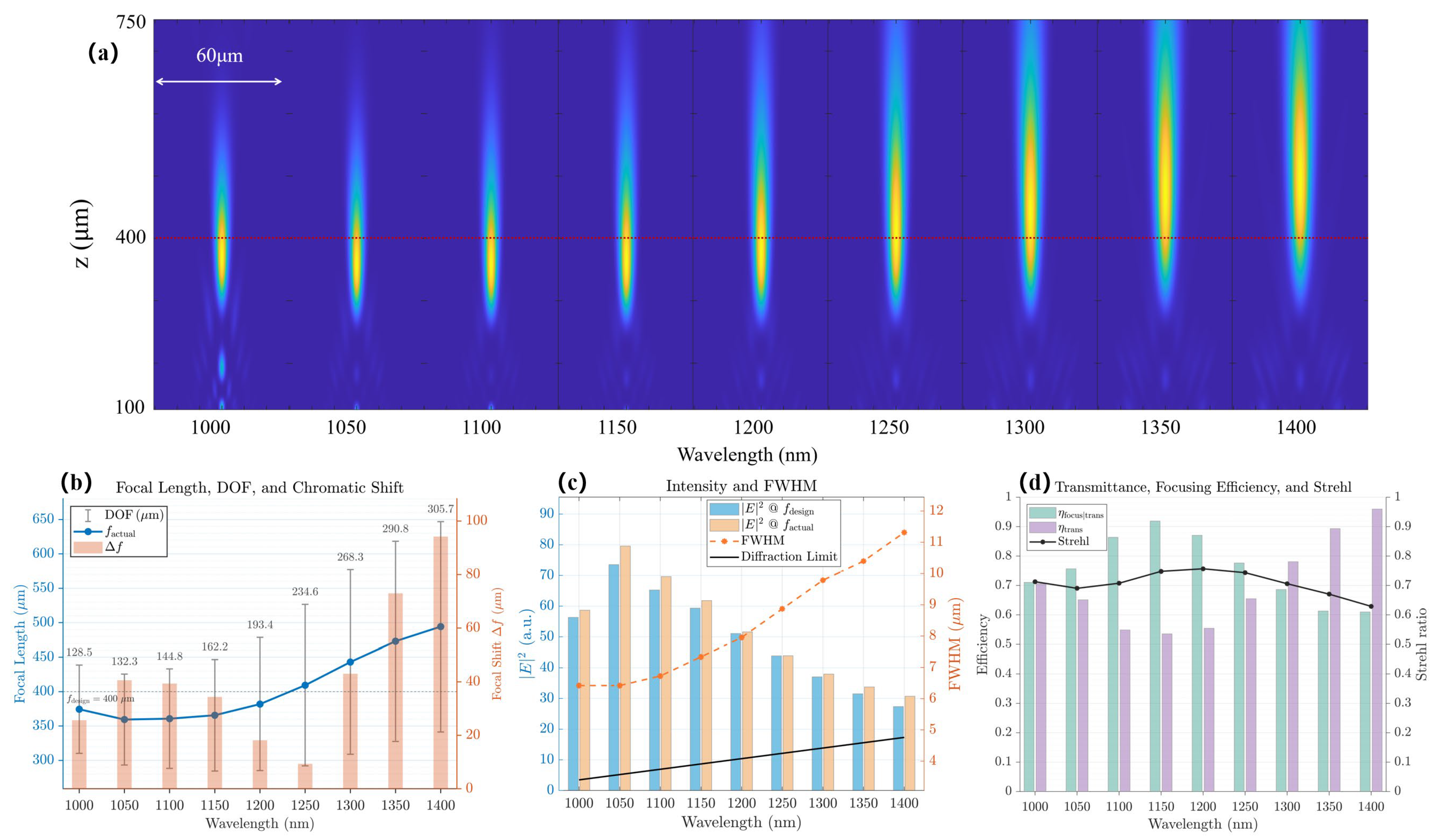
The designed metalens was simulated using FDTD methods. Figure 8a shows the x-z plane intensity distributions at multiple discrete wavelengths. It can be observed that the focal spot consistently remains near the target focal length across the full spectral range, exhibiting symmetric and well-confined focal profiles. This indicates that the structure achieves effective phase modulation across multiple wavelengths.
To quantitatively analyze focal length dispersion, Figure 8b plots the deviation Δ f between the actual focal length ( f a c t u a l ) and the target focal length ( f d e s i g n   =   400   μ m ) for each wavelength. In the 1000–1200 nm range, the focal length remains relatively stable with minimal shift. As the wavelength increases beyond 1250 nm, a moderate focal regression is observed, yet the maximum deviation remains below 100 μm. Notably, the depth of focus (gray error bars) increases with wavelength, providing axial tolerance and mitigating the performance impact of focus shifts. This demonstrates the design’s strong capability in maintaining focal consistency, achieving quasi-achromatic behavior across the target band.
Figure 8c further analyzes the intensity at the focal plane and the variation in the full width at half maximum (FWHM) with respect to wavelength. Both at f d e s i g n and f a c t u a l , the focal intensity remains high, indicating good focusing efficiency and depth-of-focus tolerance. However, the FWHM curve (orange dashed line) deviates from the theoretical diffraction limit (black solid line), suggesting that although the resolution does not fully reach the diffraction limit, it remains within an acceptable range with consistent broadband-focusing trends.
System-level metrics in Figure 8d reinforce these observations: the transmittance η t r a n s is consistently high with modest variation, the focusing efficiency referenced to transmitted power η f o c u s | t r a n s remains elevated, and the Strehl ratio is near-flat and high across the band. Together, the small f , near-limit FWHM, and stable efficiency/quality metrics demonstrate quasi-achromatic behavior of metalens over 1000–1400 nm. Additional quantitative comparison with previously reported achromatic metalenses and concise manufacturability assessment are provided in Appendix B and Table A1.
In summary, the broadband simulation results validate the feasibility of the proposed design framework for multi-wavelength focusing tasks, highlighting its potential in broadband achromatic metalens applications.

4. Conclusions

In conclusion, we have proposed a transformer-based deep learning forward prediction network, SiDSaT, and demonstrated its feasibility for efficient and effective inverse design of achromatic metalenses. Incorporating a Shape-integrated module and dual attention mechanisms (GPT and LPT), SiDSaT can accommodate various geometric types and wavelength regimes in a single training session. We utilized SiDSaT to predict the phase for cylindrical and rectangular meta-atoms over wavelengths from 800 nm to 1600 nm, achieving mean absolute errors of 0.0473 and 0.0446, respectively. This shows that SiDSaT achieves highly accurate phase prediction across the full spectral range for various structural types. Furthermore, we conducted ablation studies to validate the proposed model’s architecture.
To verify the adaptability of SiDSaT, we integrated it into an inverse design framework (PSO-GA) and accomplished metalens designs for both single-wavelength and broadband applications. Particularly, based on the asymptotic phase compensation method, we performed a constraint analysis for the achromatic metalens design, which lowered the algorithm’s computational cost. Using the SiDSaT-embedded PSO-GA strategy, we obtained four single-wavelength metalens designs at 850 nm, 1064 nm, and 1310 nm. The resulting focal spots have FWHM values approaching the diffraction limit, confirming the framework’s high accuracy and reliability in narrowband design tasks. Moreover, we applied the framework to the design of an achromatic metalens for the 1000–1400 nm wavelength range. Simulation results show an approximately constant focal length across this operating band, demonstrating the framework’s effectiveness even when nonlinear dispersion compensation is required.
Above all, the proposed SiDSaT-embedded inverse design framework not only exhibits highly accurate modeling and efficient structure-search capabilities but also demonstrates strong adaptability and generalization in practical design tasks. In addition, by replacing traditional FDTD simulations with SiDSaT for phase prediction, the overall computational efficiency of the design pipeline improves by approximately two orders of magnitude, significantly accelerating the design process without compromising accuracy. This approach provides a powerful solution for the intelligent design of complex metasurface optical devices across multiple wavelengths and target specifications.

Author Contributions

Conceptualization, X.B., X.C. and Z.X. (Zhongyang Xing); methodology, X.B., J.L. and Z.H.; software, X.B., J.L. and Z.H.; validation, X.B.; investigation, J.Z. and Z.X. (Zhongjie Xu); data curation, X.B.; writing—original draft preparation, X.B.; writing—review and editing, J.Z. and Z.X. (Zhongyang Xing); supervision, X.C., Z.X. (Zhongjie Xu) and Z.X. (Zhongyang Xing); funding acquisition, Z.X. (Zhongyang Xing). All authors have read and agreed to the published version of the manuscript.

Funding

This research was supported by the National Natural Science Foundation of China (12204541).

Institutional Review Board Statement

Not applicable.

Informed Consent Statement

Not applicable.

Data Availability Statement

Data will be made available on request.

Acknowledgments

We thank Yueqiang Hu and Yuting Jiang from Hunan University, and Research Fellow Haoqian Wang from National University of Defense Technology for the useful discussions.

Conflicts of Interest

The authors declare no conflicts of interest.

Abbreviations

The following abbreviations are used in this manuscript:
BNNsBidirectional Neural Networks
BAMLsComparison of Broadband Achromatic Metalenses
DNNsDeep Neural Networks
DOFDepth of Focus
EMElectromagnetic
FCNsFully Connected Networks
FCLFully Connected Layer
FDTDFinite-Difference Time-Domain
FWHMFull Width at Half Maximum
GPTGlobal Perception Transformer
LPTLocal Perception Transformer
MAEMean Absolute Error
NANumerical Aperture
NFFNorm and Feed Forward
NTNsNeural Tensor Networks
PSOParticle Swarm Optimization
GAGenetic Algorithm
SiDSaTShape-integrated Dual-Spectrum-aware Transformer

Appendix A

Appendix A.1. Additional Validation on an All-Silicon Multi-Geometry Dataset
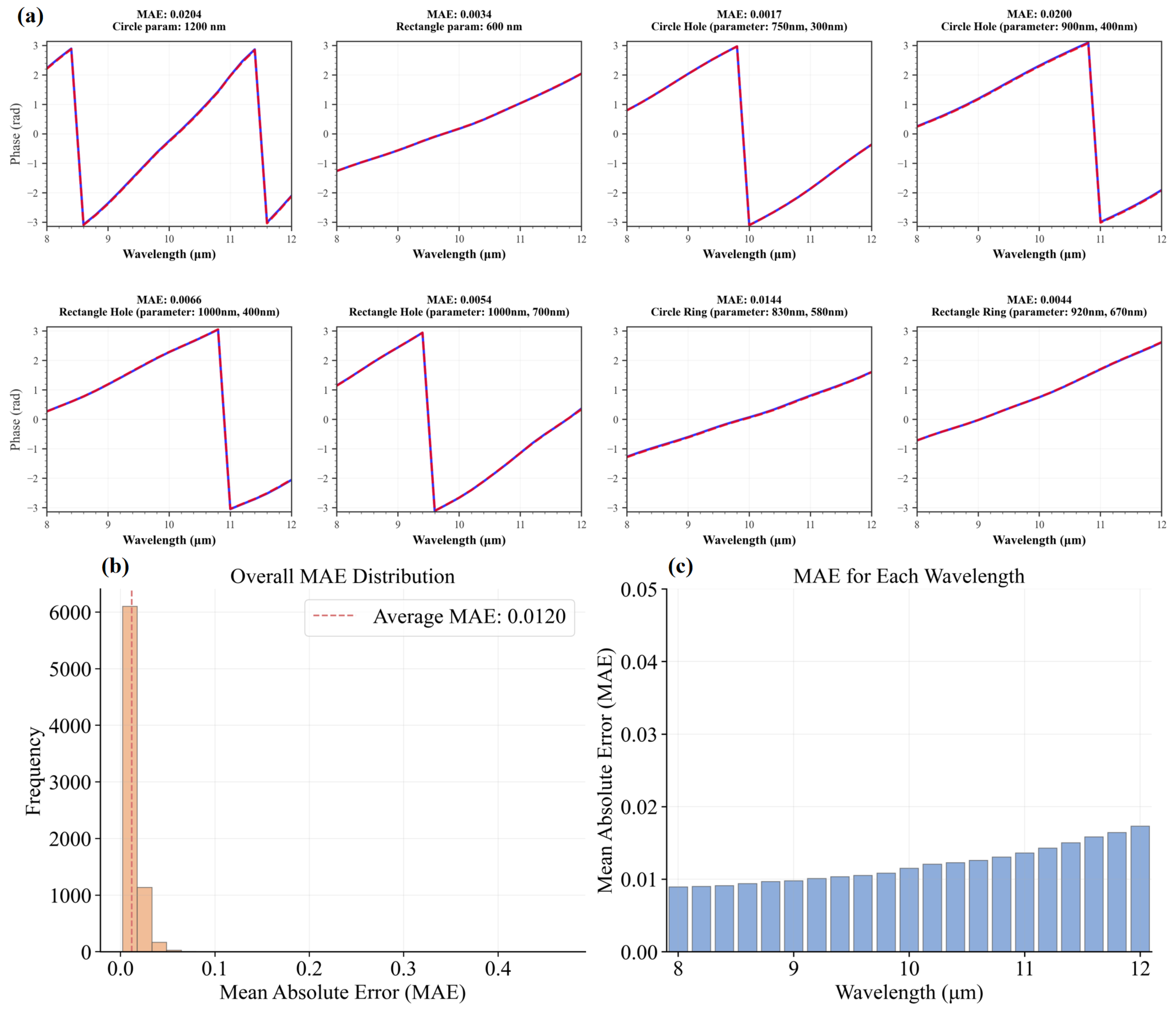
Figure A1. SiDSaT performance on the all-silicon dataset. (a) Examples of phase spectra: FDTD (blue) versus SiDSaT prediction (red) for six different shapes. (b) Histogram of sample-wise phase MAE across all 7456 samples. (c) Wavelength-wise phase MAE from 8 to 12 µm.
Photonics 12 00913 g0a1
To further demonstrate the applicability and robustness of SiDSaT beyond the main TiO2/SiO2 study, we trained and evaluated the model on a new dataset composed of all-silicon micro-pillar units [43] (period 3 μm, height 8 μm) with six different top motifs: solid circle (circle), ring (circle ring), concentric ring with central disk (circle hole), solid square (rectangle), square frame (rectangle ring), and square frame with central square (rectangle hole). The dataset contains 7456 samples spanning the 8–12 µm spectral window at 21 wavelength points. Except for the material/geometry change, the training pipeline followed the main text (same trigonometric phase loss and evaluation metrics).
Figure A1a shows a representative case with near-perfect overlap between the SiDSaT-predicted and FDTD reference phase spectra, including regions with steep spectral slopes and phase-wrapping discontinuities. The overall MAE distribution is sharply concentrated at small errors with a mean of 0.0120 rad (Figure A1b). The wavelength-wise MAE remains low across 8–12 µm with only a mild upward trend toward the band edge (Figure A1c), consistent with stronger dispersion at longer wavelengths. These results verify that SiDSaT generalizes well to different materials, larger feature sizes, and richer geometry families without architectural modification, supporting its use as a Shape-integrated, spectrum-aware surrogate across heterogeneous metasurface libraries.

Appendix A.2. Additional Validation on a Tandem Solar Cell (TSC) Transmittance Dataset

Figure A2. SiDSaT performance on the dataset of transmittance spectra for tandem solar cell (TSC) meta-units. (a) Examples of phase spectra: FDTD (blue) versus SiDSaT prediction (red) for six different shapes. (b) Histogram of sample-wise phase MAE across all 7456 samples. (c) Wavelength-wise phase MAE from 8 to 12 µm.
Photonics 12 00913 g0a2
To further assess the applicability and extensibility of SiDSaT to materials, shapes, and scales beyond metalenses, we trained the model on a transmission–spectrum dataset of tandem solar cell (TSC) meta-units [44]. Each unit is a three-layer stack with fixed thicknesses (top to bottom): 100 nm ZnO (optical resonator), 250 nm CH3NH3PbBr3 (perovskite absorber), and 100 nm TiO2 (carrier-transport layer). The top resonator spans nine pattern classes, including cross, square, L-shaped plates, square apertures (“window” patterns), and their inverted counterparts (plate↔aperture), covering a wide morphological variety. Unlike the metalens library, the unit cell lateral dimension is variable in the range 100–3200 nm. Spectra are sampled from 400 to 1200 nm at 80 wavelength points, yielding 10,578 labeled samples.
Because the target is transmittance T ( λ ) [ 0 ,   1 ] rather than phase, we replaced the sine–cosine output heads with a single transmittance head and trained SiDSaT with a mean-squared-error (MSE) loss on T ( λ ) ; all other architectural components (Shape-integrated module; Global/Local Perception transformers) were unchanged.
Trained on this dataset, SiDSaT attains an average MAE of 0.0110 and an average MSE of 0.0013 over the entire dataset, outperforming a CNN baseline reported in the original study (MSE = 0.00375). Representative predictions in Figure A2a show close overlap between the SiDSaT-predicted and FDTD transmittance spectra across diverse patterns and resonant behaviors (sharp peaks and broadband plateaus). The overall MAE distribution is tightly concentrated near zero with the mean indicated at 0.0110 (Figure A2b). The wavelength-wise MAE (Figure A2c) remains low across 400–1200 nm, with slightly higher errors around short-wavelength resonances. These results confirm that SiDSaT generalizes effectively to heterogeneous multilayer materials, mixed pattern families, and variable unit cell dimensions, requiring only a task-level change in the output head and loss. The Shape-integrated priors and global–local spectral attention enable accurate modeling of both narrow resonances and broadband backgrounds, supporting SiDSaT as a versatile surrogate for metasurface-related transmission problems beyond phase-only tasks.

Appendix B

Table A1. Comparison of Broadband Achromatic Metalenses (BAMLs).
ReferenceOperating Band (nm)Focal LengthMax Focal ShiftNAMaterialsAchromatization StrategyOperation Mode and Polarization
Our work1000–1400400 μm≈90 μm (22.5%)0.080TiO2 nanopillars on SiO2 substrateAsymptotic phase compensation; Primitive meta-atom; SiDSaT-embedded PSO-GA strategyTransmission;
Polarization insensitive
1000–1300≈40 μm (10%)
Wang et al. [45] (2017)1200–1680100 μm≈20 μm (20%)0.268Au multi-nanorods/SiO2 spacer/Au back reflector (on Si substrate)Integrated Resonant UnitReflection;
Polarization selective
Hsiao et al. [46] (2018)420–650150 μm≈30 μm (20%)0.124Al multi-nanorods/SiO2 spacer/Al back reflector (on Si substrate)Integrated Resonant UnitReflection;
Polarization selective
Shrestha et al. [16] (2018)1200–1650200 μm≈30 μm (15%)0.24a-Si nanopillars on fused silicaComplex meta-atomTransmission;
Polarization insensitive
Sun et al. [47] (2022)450–1400214 μm≈25 μm (12%)0.107Si3N4 nanopillars on fused silicaAperture Partition and Phase Coordination Method (APPCM, dual-lens-zone design)Transmission;
Polarization selective
Hu et al. [18] (2023)400–1000150 μm≈32 μm (21%)0.164TiO2 nanopillars on SiO2 substrateAsymptotic phase compensation; Complex meta-atomTransmission;
Polarization insensitive
Li & Lv [48] (2024)1000–12506.5 μm≈0 μm0.5Si nanopillars on SiO2 substratePSO-GA hybrid optimizationTransmission;
Polarization selective
Song et al. [49] (2024)430–75050 μm≈6 μm (12%)0.255LNOI thin film on LNOI substrateMulti-Zone Taylor Expansion Method (MZTEM)Transmission;
Polarization insensitive
Hou et al. [42] (2025)450–65060 μm≈3 μm (5%)0.164TiO2 anisotropic nanopillars on SiO2 substrateAnisotropic nanofin phase control with PSOTransmission;
Polarization selective
Table A1 compares our broadband design against representative published BAMLs across the visible to NIR. Over 1000–1400 nm, our lens (D = 60 µm, f = 400 µm, NA ≈ 0.08) exhibits a maximum focal shift of ≈90 µm (22.5%), which improves to ≈40 µm (10%) when restricted to 1000–1300 nm. These values are comparable to prior transmission-mode reports: Sun [47] (2022) ≈ 12% at NA = 0.107 (450–1400 nm), Shrestha [16] (2018) ≈ 15% at NA = 0.24 (1200–1650 nm), and Hu [18] (2023) ≈ 21% at NA = 0.164 (400–1000 nm). Some reflection-mode or visible-band designs report ≤ 5–12% focal shift, but they often operate under different regimes—namely, polarization-selective metalenses that work only for LCP/RCP incidence, and devices with very short focal lengths and tiny apertures—both of which limit generality and practical utility. For our design, even the worst-case Δf at 1400 nm remains well within the depth of focus DOF, consistent with the stable peak-intensity and FWHM trends in Figure 8c.
From a fabrication standpoint, our design avoids multilayer metal back reflectors, anisotropic nanofins, multi-stack alignments, and other similar approaches that generally require additional deposition/etch steps, tighter CD/overlay control, and higher aspect ratios. By using simple-geometry TiO2 pillars on SiO2 (single-layer dielectric patterning and one etch) and a minimum pillar diameter > 200 nm, the required aspect ratio remains within standard EBL/DUV + hard-mask ICP-RIE capability, widening the process window and improving manufacturability without sacrificing broadband achromatic performance.

References

  1. Chen, W.T.; Zhu, A.Y.; Capasso, F. Flat Optics with Dispersion-Engineered Metasurfaces. Nat. Rev. Mater. 2020, 5, 604–620. [Google Scholar] [CrossRef]
  2. Liu, Y.; Zhang, X. Metamaterials: A New Frontier of Science and Technology. Chem. Soc. Rev. 2011, 40, 2494–2507. [Google Scholar] [CrossRef] [PubMed]
  3. Yuan, Q.; Ge, Q.; Chen, L.; Zhang, Y.; Yang, Y.; Cao, X.; Wang, S.; Zhu, S.; Wang, Z. Recent Advanced Applications of Metasurfaces in Multi-Dimensions. Nanophotonics 2023, 12, 2295–2315. [Google Scholar] [CrossRef] [PubMed]
  4. Zhang, L.; Zhou, C.; Liu, B.; Ding, Y.; Ahn, H.-J.; Chang, S.; Duan, Y.; Rahman, M.T.; Xia, T.; Chen, X.; et al. Real-Time Machine Learning–Enhanced Hyperspectro-Polarimetric Imaging via an Encoding Metasurface. Sci. Adv. 2024, 10, eadp5192. [Google Scholar] [CrossRef]
  5. Faraon, A.; Arbabi, A.; Kamali, S.M.; Arbabi, E.; Majumdar, A. Applications of Wavefront Control Using Nano-Post-Based Dielectric Metasurfaces. In Dielectric Metamaterials; Woodhead Publishing: Duxford, UK, 2020; pp. 175–194. [Google Scholar] [CrossRef]
  6. Mo, H.; Ji, Z.; Zheng, Y.; Liang, W.; Yu, H.; Li, Z. Broadband Achromatic Imaging of Metasurface Lenses (Invited). Infrared Laser Eng. 2021, 50, 40–49. [Google Scholar]
  7. Zhou, Y.; Liang, G.; Wen, Z.; Zhang, Z.; Shang, Z.; Chen, G. Research Progress on Optical Super-Resolution Planar Metasurface Lenses. Opto-Electron. Eng. 2021, 48, 13–31. [Google Scholar]
  8. Zheng, Y.; Qin, F.; Li, X. Research Progress on Super-Diffraction-Limit Light Field Manipulation of Supercritical Lenses (Invited). Acta Photonica Sin. 2022, 51, 174–186. [Google Scholar]
  9. Tang, J.; Gong, Y.; Pang, K. Two-Dimensional Metasurfaces: Applications and Research Progress in Metalenses. Laser Optoelectron. Prog. 2023, 60, 43–57. [Google Scholar]
  10. Khorasaninejad, M.; Chen, W.T.; Devlin, R.C.; Oh, J.; Zhu, A.Y.; Capasso, F. Metalenses at Visible Wavelengths: Diffraction-Limited Focusing and Subwavelength Resolution Imaging. Science 2016, 352, 1190–1194. [Google Scholar] [CrossRef]
  11. Hu, Y.; Ou, X.; Zeng, T.; Lai, J.; Zhang, J.; Li, X.; Luo, X.; Li, L.; Fan, F.; Duan, H. Electrically Tunable Multifunctional Polarization-Dependent Metasurfaces Integrated with Liquid Crystals in the Visible Region. Nano Lett. 2021, 21, 4554–4562. [Google Scholar] [CrossRef]
  12. Li, L.; Zhang, J.; Hu, Y.; Lai, J.; Wang, S.; Yang, P.; Li, X.; Duan, H. Broadband Polarization-switchable Multi-focal Noninterleaved Metalenses in the Visible. Laser Photonics Rev. 2021, 15, 2100198. [Google Scholar] [CrossRef]
  13. Khorasaninejad, M.; Zhu, A.Y.; Roques-Carmes, C.; Chen, W.T.; Oh, J.; Mishra, I.; Devlin, R.C.; Capasso, F. Polarization-Insensitive Metalenses at Visible Wavelengths. Nano Lett. 2016, 16, 7229–7234. [Google Scholar] [CrossRef] [PubMed]
  14. Xing, Z.; Liao, J.; Xu, Z.; Cheng, X.; Zhang, J. The Design of Highly Reflective All-Dielectric Metasurfaces Based on Diamond Resonators. Photonics 2024, 11, 1015. [Google Scholar] [CrossRef]
  15. Khorasaninejad, M.; Shi, Z.; Zhu, A.Y.; Chen, W.T.; Sanjeev, V.; Zaidi, A.; Capasso, F. Achromatic Metalens over 60 Nm Bandwidth in the Visible and Metalens with Reverse Chromatic Dispersion. Nano Lett. 2017, 17, 1819–1824. [Google Scholar] [CrossRef]
  16. Shrestha, S.; Overvig, A.C.; Lu, M.; Stein, A.; Yu, N. Broadband Achromatic Dielectric Metalenses. Light Sci. Appl. 2018, 7, 85. [Google Scholar] [CrossRef]
  17. Chen, W.T.; Zhu, A.Y.; Sanjeev, V.; Khorasaninejad, M.; Shi, Z.; Lee, E.; Capasso, F. A Broadband Achromatic Metalens for Focusing and Imaging in the Visible. Nat. Nanotechnol. 2018, 13, 220–226. [Google Scholar] [CrossRef]
  18. Hu, Y.; Jiang, Y.; Zhang, Y.; Yang, X.; Ou, X.; Li, L.; Kong, X.; Liu, X.; Qiu, C.-W.; Duan, H. Asymptotic Dispersion Engineering for Ultra-Broadband Meta-Optics. Nat. Commun. 2023, 14, 6649. [Google Scholar] [CrossRef]
  19. Cano-Renteria, F.; Tegmark, M.; Soljacic, M.; Joannopoulos, J.D.; Peurifoy, J.; Shen, Y.; Jing, L.; Yang, Y.; DeLacy, B.G. Nanophotonic Particle Simulation and Inverse Design Using Artificial Neural Networks. In Proceedings of the Physics and Simulation of Optoelectronic Devices XXVI, San Francisco, CA, USA, 29 January–1 February 2018; Osiński, M., Arakawa, Y., Witzigmann, B., Eds.; SPIE: San Francisco, CA, USA, 2018; p. 6. [Google Scholar]
  20. Yu, N.; Genevet, P.; Kats, M.A.; Aieta, F.; Tetienne, J.-P.; Capasso, F.; Gaburro, Z. Light Propagation with Phase Discontinuities: Generalized Laws of Reflection and Refraction. Science 2011, 334, 333–337. [Google Scholar] [CrossRef]
  21. Huang, H.; Overvig, A.C.; Xu, Y.; Malek, S.C.; Tsai, C.-C.; Alù, A.; Yu, N. Leaky-Wave Metasurfaces for Integrated Photonics. Nat. Nanotechnol. 2023, 18, 580–588. [Google Scholar] [CrossRef]
  22. Jiang, X.; Yuan, H.; Chen, D.; Zhang, Z.; Du, T.; Ma, H.; Yang, J. Metasurface Based on Inverse Design for Maximizing Solar Spectral Absorption. Adv. Opt. Mater. 2021, 9, 2100575. [Google Scholar] [CrossRef]
  23. An, S.; Fowler, C.; Zheng, B.; Shalaginov, M.Y.; Tang, H.; Li, H.; Zhou, L.; Ding, J.; Agarwal, A.M.; Rivero-Baleine, C.; et al. A Deep Learning Approach for Objective-Driven All-Dielectric Metasurface Design. ACS Photonics 2019, 6, 3196–3207. [Google Scholar] [CrossRef]
  24. Gao, Y.; Chen, W.; Li, F.; Zhuang, M.; Yan, Y.; Wang, J.; Wang, X.; Dong, Z.; Ma, W.; Zhu, J. Meta-attention Deep Learning for Smart Development of Metasurface Sensors. Adv. Sci. 2024, 11, 2405750. [Google Scholar] [CrossRef]
  25. Lv, J.; Zhang, R.; Liu, C.; Ge, Z.; Gu, Q.; Feng, F.; Si, G. Polarization-Controlled Metasurface Design Based on Deep ResNet. Opt. Laser Technol. 2024, 179, 111396. [Google Scholar] [CrossRef]
  26. Ji, W.; Chang, J.; Xu, H.-X.; Gao, J.R.; Gröblacher, S.; Urbach, H.P.; Adam, A.J.L. Recent Advances in Metasurface Design and Quantum Optics Applications with Machine Learning, Physics-Informed Neural Networks, and Topology Optimization Methods. Light Sci. Appl. 2023, 12, 169. [Google Scholar] [CrossRef]
  27. Ma, W.; Liu, Z.; Kudyshev, Z.A.; Boltasseva, A.; Cai, W.; Liu, Y. Deep Learning for the Design of Photonic Structures. Nat. Photonics 2021, 15, 77–90. [Google Scholar] [CrossRef]
  28. Kanmaz, T.B.; Ozturk, E.; Demir, H.V.; Gunduz-Demir, C. Deep-Learning-Enabled Electromagnetic near-Field Prediction and Inverse Design of Metasurfaces. Optica 2023, 10, 1373. [Google Scholar] [CrossRef]
  29. Ma, T.; Wang, H.; Guo, L.J. OptoGPT: A Foundation Model for Inverse Design in Optical Multilayer Thin Film Structures. Opto-Electron. Adv. 2024, 7, 240062. [Google Scholar] [CrossRef]
  30. An, S.; Zheng, B.; Shalaginov, M.Y.; Tang, H.; Li, H.; Zhou, L.; Ding, J.; Agarwal, A.M.; Rivero-Baleine, C.; Kang, M.; et al. Deep Learning Modeling Approach for Metasurfaces with High Degrees of Freedom. Opt. Express 2020, 28, 31932. [Google Scholar] [CrossRef] [PubMed]
  31. Hong, P.; Hu, L.; Zhou, Z.; Qin, H.; Chen, J.; Fan, Y.; Yin, T.; Kou, J.; Lu, Y. Recent Advances in Inverse Design for Photonics (Invited). Acta Photonica Sin. 2023, 52, 9–32. [Google Scholar]
  32. Madina; Cheng, H.; Tian, J.; Chen, S. Inverse Design Methods and Applications for Artificial Photonic Devices (Invited). Acta Photonica Sin. 2022, 51, 174–195. [Google Scholar]
  33. An, X. Design of Broadband Achromatic Metalens Based on Deep Learning. Master’s Thesis, Huazhong University of Science and Technology, Wuhan, China, 2021. [Google Scholar]
  34. Malkiel, I.; Mrejen, M.; Nagler, A.; Arieli, U.; Wolf, L.; Suchowski, H. Plasmonic Nanostructure Design and Characterization via Deep Learning. Light Sci. Appl. 2018, 7, 60. [Google Scholar] [CrossRef]
  35. Gao, L.; Li, X.; Liu, D.; Wang, L.; Yu, Z. A Bidirectional Deep Neural Network for Accurate Silicon Color Design. Adv. Mater. 2019, 31, 1905467. [Google Scholar] [CrossRef] [PubMed]
  36. Nadell, C.C.; Huang, B.; Malof, J.M.; Padilla, W.J. Deep Learning for Accelerated All-Dielectric Metasurface Design. Opt. Express 2019, 27, 27523. [Google Scholar] [CrossRef] [PubMed]
  37. Liu, Z.; Zhu, D.; Rodrigues, S.P.; Lee, K.-T.; Cai, W. Generative Model for the Inverse Design of Metasurfaces. Nano Lett. 2018, 18, 6570–6576. [Google Scholar] [CrossRef]
  38. Gu, Y.; Harlim, J.; Liang, S.; Yang, H. Stationary Density Estimation of Itô Diffusions Using Deep Learning. SIAM J. Numer. Anal. 2023, 61, 45–82. [Google Scholar] [CrossRef]
  39. An, S.; Zheng, B.; Julian, M.; Williams, C.; Tang, H.; Gu, T.; Zhang, H.; Kim, H.J.; Hu, J. Deep Neural Network Enabled Active Metasurface Embedded Design. Nanophotonics 2022, 11, 4149–4158. [Google Scholar] [CrossRef]
  40. Chen, W.; Gao, Y.; Li, Y.; Yan, Y.; Ou, J.-Y.; Ma, W.; Zhu, J. Broadband Solar Metamaterial Absorbers Empowered by Transformer-Based Deep Learning. Adv. Sci. Weinh. Baden-Wurtt. Ger. 2023, 10, e2206718. [Google Scholar] [CrossRef]
  41. Yu, Q.; Shen, X.; Yi, L.; Liang, M.; Li, G.; Guan, Z.; Wu, X.; Castel, H.; Hu, B.; Yin, P.; et al. Fragment-Fusion Transformer: Deep Learning-Based Discretization Method for Continuous Single-Cell Raman Spectral Analysis. ACS Sens. 2024, 9, 3907–3920. [Google Scholar] [CrossRef]
  42. Hou, L.; Zhou, H.; Zhang, D.; Lu, G.; Zhang, D.; Liu, T.; Xiao, S.; Yu, T. High-Efficiency Broadband Achromatic Metalens in the Visible. Appl. Phys. Lett. 2025, 126, 101704. [Google Scholar] [CrossRef]
  43. Wu, H. Research on Long-Wave Infrared Broadband Achromatic Metalens. Master’s Thesis, Huazhong University of Science and Technology, Wuhan, China, 2021. [Google Scholar]
  44. Razi, A.; Safdar, A.; Irfan, R. Enhancing Tandem Solar Cell’s Efficiency through Convolutional Neural Network-Based Optimization of Metasurfaces. Mater. Des. 2023, 236, 112475. [Google Scholar] [CrossRef]
  45. Wang, S.; Wu, P.C.; Su, V.-C.; Lai, Y.-C.; Hung Chu, C.; Chen, J.-W.; Lu, S.-H.; Chen, J.; Xu, B.; Kuan, C.-H.; et al. Broadband Achromatic Optical Metasurface Devices. Nat. Commun. 2017, 8, 187. [Google Scholar] [CrossRef]
  46. Hsiao, H.; Chen, Y.H.; Lin, R.J.; Wu, P.C.; Wang, S.; Chen, B.H.; Tsai, D.P. Integrated Resonant Unit of Metasurfaces for Broadband Efficiency and Phase Manipulation. Adv. Opt. Mater. 2018, 6, 1800031. [Google Scholar] [CrossRef]
  47. Sun, P.; Zhang, M.; Dong, F.; Feng, L.; Chu, W. Broadband Achromatic Polarization Insensitive Metalens over 950 Nm Bandwidth in the Visible and Near-Infrared. Chin. Opt. Lett. 2022, 20, 13601. [Google Scholar] [CrossRef]
  48. Li, Z.; Lv, Y. Optimization for Si Nano-Pillar-Based Broadband Achromatic Metalens. IEEE Photonics J. 2024, 16, 5000307. [Google Scholar] [CrossRef]
  49. Song, R.; Lu, X.; Wang, F.; Song, X.; Chen, Z.; Li, Y. Multi-Zone Taylor Expansion Method for Broadband Achromatic Polarization-Insensitive Metalens Design. Phys. Scr. 2024, 99, 25530. [Google Scholar] [CrossRef]
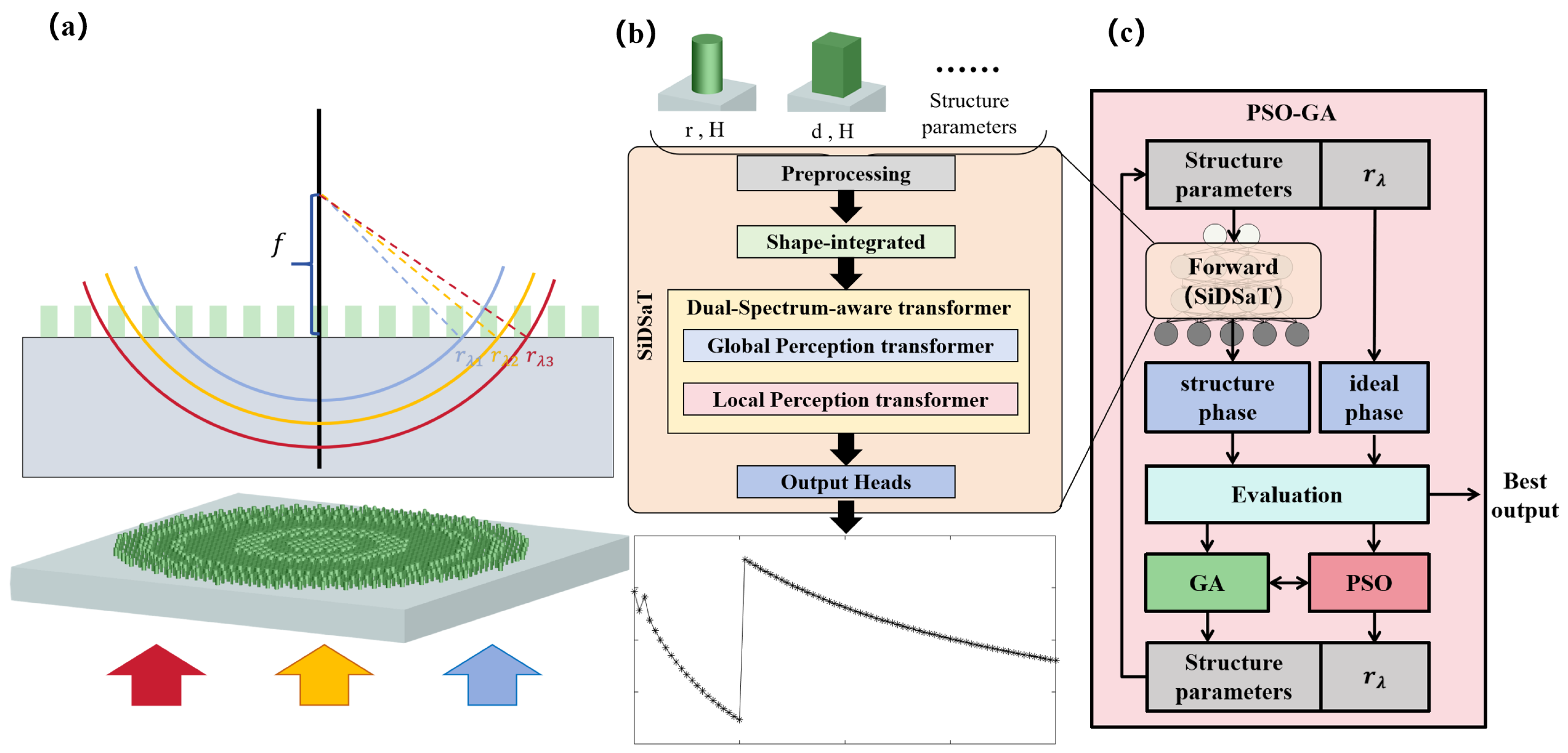
Figure 1. Intelligent design methodology for metalenses based on SiDSaT forward modeling and PSO-GA optimization. (a) Schematic of the metalens-focusing principle, where multi-wavelength light is brought to a common focal point through structural dispersion engineering; (b) workflow of the proposed forward prediction network SiDSaT, which integrates structural information and Shape-integrated modules, and performs spectral modeling via Dual-Spectrum-aware transformer branches; (c) inverse design framework based on PSO-GA, where SiDSaT provides fast and accurate phase predictions for candidate structures, enabling iterative comparison with the target phase profile and efficient search for optimal structural parameters.
Photonics 12 00913 g001
Figure 2. The architecture of the forward prediction network SiDSaT. (a) Overall network pipeline: starting from input structural parameters and shape type, the data passes through a preprocessing module, fully connected mapping, the Shape-integrated module, and the dual-transformer module (composed of GPT and LPT), ultimately producing the predicted spectral response; (b) structure and gating mechanism of the Shape-integrated module, which performs weighted enhancement of geometric and shape features; (c) the details of cross-attention mechanism in GPT for inter-fragment multi-head attention; (d) the details of self-attention mechanism in LPT for intra-fragment multi-head attention.
Photonics 12 00913 g002
Figure 3. (a) Schematic of linear phase compensation. The wavefront for each wavelength is centered at a fixed position, resulting in limited achromatic performance; (b) schematic of asymptotic phase compensation. Each wavelength is assigned a shiftable wavefront center r λ , enabling nonlinear phase dispersion control; (c) geometric constraints derived from the bandwidth coverage condition of the phase dispersion range χ.
Photonics 12 00913 g003
Figure 4. PSO-GA optimization framework. PSO performs local structural parameter search guided by SiDSaT predictions, while GA handles global crossover and mutation. The best individual is selected based on the phase fitness function.
Photonics 12 00913 g004
Figure 5. Prediction performance and error analysis of the SiDSaT model on in-distribution and out-of-distribution samples. (a) Predicted phase responses of cylindrical and rectangular metasurface units within the dataset, compared against FDTD simulations; (b) generalization predictions on unseen unit cell geometries, demonstrating robustness across shape and parameter variations; (c) wavelength-wise mean absolute error (MAE) of SiDSaT predictions across the test set, comparing error trends for circular and rectangular unit cells.
Photonics 12 00913 g005
Figure 6. Validation loss comparison in ablation study of SiDSaT model modules. The inset in the upper-right corner shows a magnified view of the late training stage (Epochs 3000–4000).
Photonics 12 00913 g006
Figure 7. Simulated focusing performance of single-wavelength metalenses designed via the SiDSaT-PSO-GA framework. (ad) Simulated optical intensity distributions (top) and focal plane intensity profiles (bottom) for four single-wavelength metalenses (Metalens 1–4).
Photonics 12 00913 g007
Figure 8. Evaluation of broadband achromatic metalens-focusing performance. (a) Simulated electric field intensity distributions in the x–z plane for wavelengths ranging from 1000 to 1400 nm, showing consistent focusing positions near the design focal length of 400 μm; (b) chromatic dispersion analysis by comparing the actual focal length f a c t u a l   (blue line) with the design target f d e s i g n   =   400   μ m , and plotting the corresponding focal shift f   (orange bars) and depth of focus (gray error bars); (c) wavelength-dependent trends of peak focal intensity and FWHM at both f d e s i g n (blue bars) and f a c t u a l (yellow bars), with the FWHM (orange dashed line) compared against the theoretical diffraction limit (solid line), F W H M D L   =   0.514 λ f a c t u a l / D . (d) Transmittance efficiency η t r a n s (teal bars), focusing efficiency η f o c u s | t r a n s (purple bars), and Strehl ratio (black line).
Photonics 12 00913 g008
Table 1. Geometric specifications and focusing performance of designed single-wavelength metalenses for inverse design validation.
Metalens 1Metalens 2Metalens 3Metalens 4
Wavelength850 nm850 nm1064 nm1310 nm
Diameter60 μm60 μm40 μm40 μm
Target Focal Length200 μm100 μm50 μm50 μm
Actual Focal Length199.2 μm101.0 μm48.7 μm50.0 μm
NA0.14830.28730.37140.3714
FWHM3.058 μm1.834 μm1.644 μm2.060 μm
Focus Ratio1.041.211.121.14
DOF35.760 μm10.835 μm7.504 μm8.109 μm
η t r a n s 0.60410.87980.81160.8428
η f o c u s | t r a n s 0.76440.74090.69210.6289
Strehl Ratio0.91080.71940.74980.6314
Disclaimer/Publisher’s Note: The statements, opinions and data contained in all publications are solely those of the individual author(s) and contributor(s) and not of MDPI and/or the editor(s). MDPI and/or the editor(s) disclaim responsibility for any injury to people or property resulting from any ideas, methods, instructions or products referred to in the content.