Article

Reinforcement Learning Compensatory-Based Fully Actuated Control Method for Risley Prisms

1
Xi’an Institute of Optics and Precision Mechanics, Chinese Academy of Sciences, Xi’an 710119, China
2
University of Chinese Academy of Sciences, Beijing 100049, China
3
Key Laboratory of Space Precision Measurement Technology, Chinese Academy of Sciences, Xi’an 710119, China
4
Pilot National Laboratory for Marine Science and Technology, Qingdao 266237, China
5
Laoshan Laboratory, Laoshan 266100, China
*
Author to whom correspondence should be addressed.
Photonics 2025, 12(9), 885; https://doi.org/10.3390/photonics12090885
Submission received: 2 August 2025 / Revised: 27 August 2025 / Accepted: 28 August 2025 / Published: 2 September 2025
(This article belongs to the Special Issue Laser Communication Systems and Related Technologies)

Abstract

Beam pointing control based on Risley prisms is of great significance in wide-angle, high-precision application scenarios, such as laser communication, but its inherent nonlinear system characteristics seriously restrict the performance of beam pointing control, such as accuracy. For this reason, this paper combines the theory of fully actuated control with reinforcement learning methods and designs a fully actuated control method based on reinforcement learning compensation: suppressing the influence of system nonlinearity through fully actuated control, using reinforcement learning to estimate system perturbations and nonlinearities, and then outputting a compensated control quantity using the low-dimensional output of fully actuated control as the reference input of reinforcement learning reduces the complexity of learning and realises the end-to-end uncertainty estimation. Finally, the stability of the method is theoretically analyzed, and the effectiveness of the method is verified by experimental analysis, which can further improve the beam pointing accuracy of the Risley prism system.

1. Introduction

Beam control technology as the core link to realize high-bandwidth and low-latency space information transmission plays a crucial role in the field of laser communication. In order to establish and maintain a stable and reliable optical communication connection in dynamically changing interstellar or space–ground links, high-precision and wide-angle pointing control of laser beams is an indispensable key technology [1,2]. There are currently many beam control methods, such as Liquid Crystal Phase Arrays, Fast Steering Mirror Compensation, and Risley prisms. Liquid Crystal Phase Arrays are a programmable, non-mechanical beam deflection technology that uses electrical signals to control the phase of each unit in a liquid crystal spatial light modulator array, enabling inertia-free beam scanning [3]. They offer advantages such as compact size, lightweight design, and low power consumption, but their deflection range is limited, and they are susceptible to temperature fluctuations. Fast Steering Mirror Compensation is based on high-bandwidth closed-loop feedback control, using position detectors to monitor spot deviation in real time and driving fast steering mirrors for high-precision, high-speed compensation and correction [4,5,6,7]. While it offers high precision and a fast response, this method uses a large number of components, resulting in a bulky system and high power consumption. The Risley prism method, which is the focus of this paper, utilizes the optical principle of prism refraction to change the direction of light beams by controlling the rotation of two prisms with a motor. This technology plays a crucial role in applications requiring both a wide range and high precision [8]. However, this system has multiple error sources and exhibits significant nonlinearity.
The complex nonlinear relationship between the beam pointing and the prism rotation angle in Risley prism systems can lead to challenges such as the complex mapping relationship between beam deflection rate and prism rotation speed. This nonlinear mapping causes slight fluctuations in the prism rotation speed to be significantly amplified into macroscopic deviations or jitter in the beam pointing. Therefore, in high-precision applications such as laser communication and target tracking, precise and stable control of the prism rotation speed is key to overcoming system nonlinear effects and ensuring beam pointing accuracy. To solve the nonlinearity problem in the Risley prism and improve control accuracy, Ball Aerospace and Technologies Corp. introduced a third prism to enable smooth movement of the beam within the pointing range. However, this method increased the weight and complexity of the system structure, making it more difficult to calculate and control and limiting its feasibility in practical applications [9]. Sun J used a lookup table method to replace complex solutions and combined genetic algorithms with PID control algorithms to improve the control accuracy and stability of the rotating Risley prism [10]. Li A studied a cam-mechanism-based drive method to reduce the error sources caused by nonlinear motor control through physical structure, optimize system performance, and improve tracking accuracy [11]. Shen Y used a particle swarm algorithm to improve the pointing accuracy when the prism apex angle increased [12]. Li Y, Li J, Zhou Y, et al. analyzed the nonlinearity and singularity of the rotating Risley prism, explained the internal mechanism of the double prism scan in principle, and provided a theoretical basis for the nonlinear control of the double prism [13,14,15,16,17,18,19,20,21,22,23]. Ma R et al. designed a robust control algorithm based on interference observers to improve control performance [24]. Yuan L et al. improved pointing accuracy through system identification and error correction [25].
With the development of artificial intelligence technology, Yuan L et al. used a double BP neural network to alleviate the contradiction between speed and accuracy in traditional inverse solutions [26]. Torales et al. combined neural networks with PID and applied them to a Risley prism control system [27]. Yao Y conducted partial research on Risley prism control based on deep reinforcement learning [28]. However, there are still difficulties in directly applying neural-network-based artificial intelligence methods to control systems, such as high training costs and convergence difficulties [29].
The inherent nonlinear characteristics of the Risley prism system also depend on factors such as system structure [30], prism material, parameters, and environment, making it difficult to design a relatively general high-precision robust control method. At the same time, there has been little research on high-precision control algorithms for the Risley prism itself. Therefore, research on the nonlinearity and high-precision control of the Risley prism system remains important.
Fully actuated control is a control system framework that has been proposed in recent years [31,32,33]. This method has great advantages in handling complex nonlinear systems, but its control capabilities are still limited for highly uncertain or time-varying disturbance nonlinear systems. Reinforcement learning has robust nonlinear learning and adaptive capabilities and does not rely on system models, but its learning and training complexity is relatively high [34,35,36]. In response to the above issues, this paper combines reinforcement learning methods with fully actuated control. A fully actuated control method based on reinforcement learning for Risley prisms is designed to further solve the nonlinearity issues in Risley prism control and improve control accuracy. The main methods and innovations are as follows.
(1) Design of the main controller: A robust, fully actuated control model is designed for the motor control of the Risley prism. This controller overcomes the nonlinearity in some systems through full state feedback and achieves good control results.
(2) Design of reinforcement learning compensators: By using system control errors, error change rates, main controller outputs, and other factors such as reinforcement learning observations, Actor-Critic networks and reward functions are designed to further learn and estimate modeling uncertainties, such as disturbances and nonlinearities in the system, and output control compensation amounts to improve system control accuracy.
Part of the fully actuated control information is used as a reinforcement learning reference to estimate system disturbances and uncertainties end-to-end with low-dimensional information and learn the output control compensation amount. This improves the control performance of the system and reduces the complexity of reinforcement learning. At the same time, this paper also theoretically proves the stability and superiority of the method and finally verifies the effectiveness of the method through experimental analysis.

2. System Module

2.1. Risley Prism Beam Pointing Model

Figure 1 shows a schematic diagram of the Risley prism beam pointing. Prism 1 and Prism 2 are placed coaxially and can rotate independently around the Z-axis driven by a motor. The right angles of the two prisms are parallel and perpendicular to the Z-axis. The refractive indices and apex angles of the two prisms are n 1 , n 2 , α 1 and α 2 .
The rotation angles of the prisms are θ M 1 and θ M 2 , the azimuth angle of the beam is θ , defined within the range [ 0 , 2 π ] , and the deflection angle is Φ . The distance between Prism 2 and the right-side observation screen is P.
When the incident light is directed along the Z-axis in the opposite direction, the cosine of the direction of the emerging light can be obtained using the classical forward non-paraxial ray-tracing method:
K = a 1 cos θ M 1 + a 3 sin α 2 cos θ M 2 L = a 1 sin θ M 1 + a 3 sin α 2 sin θ M 2 M = a 2 a 3 cos α 2
where
a 1 = n 2 n 1 sin α 1 cos α 1 n 1 2 sin 2 α 1
a 2 = n 2 n 1 n 1 2 sin 2 α 1 cos α 1 + sin 2 α 1
a 3 = ( a 1 sin α 2 cos Δ θ a 2 cos α 2 ) + 1 n 2 2 + ( a 1 sin α 2 cos Δ θ a 2 cos α 2 ) 2
Δ θ = θ M 2 θ M 1
The deflection angle Φ and azimuth angle θ of the emitted beam are, respectively:
Φ = arccos ( M )
θ = arctan L K ; when K 0 and L 0 arctan L K + 2 π ; when K 0 and L < 0 arctan L K + π ; when K < 0
From Equation (1) ∼ Equation (6), it can be seen that the deflection angle Φ depends only on the orientation angle between the two prisms | Δ θ | . Given the deflection angle Φ of the beam target position, the following can be obtained from Equation (1) ∼ Equation (6):
| Δ θ | = arccos 1 a 1 tan α 2 a 2 + 1 2 ( a 2 + cos Φ ) × 1 n 2 2 a 2 + cos Φ cos α 2 2
Subsequently, the classic two-step method can be used to obtain two sets of solutions for the prism rotation angle.
First solution:
θ 0 = arctan L K θ M 1 = 0 , θ M 2 = | Δ θ | , K > 0 , L 0 arctan L K θ M 1 = 0 , θ M 2 = | Δ θ | + 2 π , K 0 , L 0 arctan L K θ M 1 = 0 , θ M 2 = | Δ θ | + π , K < 0
Then, synchronously rotate the two prisms to make the beam reach the specified azimuth angle θ . The synchronous rotation angle is
θ M 1 = θ θ 0
The rotation angles of prism 1 and prism 2 are, respectively,
θ 1 n = θ M 1 , θ 2 n = θ M 1 + | Δ θ |
Second solution:
θ 0 = arctan L K θ M 1 = | Δ θ | , θ M 2 = 0 , K 0 , L 0 arctan L K θ M 1 = | Δ θ | , θ M 2 = 0 + 2 π , K 0 , L < 0 arctan L K θ M 1 = | Δ θ | , θ M 2 = 0 + π , K < 0
Then, synchronously rotate the two prisms to make the beam reach the specified azimuth angle θ . The synchronous rotation angle is
θ M 1 = θ θ 0
The rotation angles of prism 1 and prism 2 are, respectively,
θ 1 n = θ M 1 + | Δ θ | , θ 2 n = θ M 1

2.2. Motor Control Models

In a rotating double prism system, the optical wedge can be rotated by a DC torque motor and bearings. The motor is fixed to the housing, and the double prism and the motor rotor are fixedly connected. Therefore, the motor and the load are rigidly connected. This method makes the system structure more compact and ensures the accuracy and stability of the control system.
In the system, the coupling effects between armature inductance, rotational inertia, and damping are fully considered. The transfer function of the load angular velocity and armature control voltage is modeled as
ω ( s ) E a ( s ) = K t L a J s 2 + ( L a B + R a J ) s + R a B + K t K e
where ω (rad/s) is the load angular velocity, L a ( H ) is the armature inductance, J ( kg · m 2 ) is the total rotational inertia of the motor shaft, R a ( Ω ) is the armature resistance, B ( N · m · s / rad ) is the equivalent viscous damping coefficient of the motor shaft, K T ( N · m / A ) is the motor torque constant, K e ( V · s / rad ) is the motor back-EMF coefficient, and E a ( V ) is the control voltage of the armature.
Set the system input voltage to u and the output angular velocity to y, and introduce a disturbance d to the system input. Then, the differential equation of the system can be expressed as
y ¨ + L a B + R a J L a J y ˙ + R a B + K T K e L a J y = K T L a J u + d
Since d θ M d t = ω , θ M is the rotation angle of the motor, which is also the rotation angle of the prism. The transfer function of the load angle and the armature control voltage is modeled as
θ M ( s ) E a ( s ) = K T L a J s 3 + ( L a B + R a J ) s 2 + ( R a B + K T K e ) s
Models can be simplified for specific engineering applications. The armature inductance L a is usually small and can be ignored. The equation is simplified to
R a J d 2 θ M d t 2 + ( R a B + K T K e ) d θ M d t = K T e a
Set the input voltage of the system to u and the angular displacement of the output to y, and introduce a disturbance d in the input of the system. The system can be expressed as
y ¨ + R a B + K T K e R a J y ˙ = K T R a J u + d
Therefore, the differential equations between the load angle, the load angular velocity, and the control voltage of the armature can be uniformly expressed as
y ¨ + η 1 y ˙ + η 0 y = b u + d
where η 1 , η 0 , b are system parameters.

2.3. Risley Prism Beam Control Model

The overall Risley prism beam pointing control system is shown in Figure 2. Based on the required beam pointing information, the target azimuth angle θ and the deviation angle Φ are input into the inverse solution model to solve for the target angle θ M that the two prisms need to rotate to. Then, the motor control model controls the two prisms to rotate to the target angle, while the regular solution model calculates the actual deviation angle and azimuth angle of the beam based on the rotation angles of the two prisms. Under the control of the controller, the actual deviation angle and azimuth angle of the beam tend to the target angle, ultimately achieving accurate pointing.

3. Methods

The fully actuated control method based on reinforcement learning mainly consists of two parts. The first part is a fully actuated controller established based on the motor model, which serves as the main controller. The second part is a reinforcement-learning-based compensation control item, which uses system errors and error change rates as reinforcement learning agent observation inputs. Through the design of a suitable Actor–Critic network, the reinforcement learning agent estimates system disturbances and nonlinear modeling uncertainties, and finally outputs a compensation value. The control amount of the fully actuated controller and the reinforcement learning compensation amount are used as the final control input amount.

3.1. Fully Actuated Controller Design

The fully actuated control system method is a general framework for the analysis and design of control systems proposed in recent years [37]. It can effectively solve nonlinear control problems, including robust control, adaptive control, disturbance suppression, optimal control, and tracking control.
A robust fully actuated control system was designed for the motor system model constructed above. It consists of two parts. The first part compensates for nonlinear terms in the system other than interference and then configures a linear system with the desired characteristic structure. The second part is a robust stabilization term to deal with the effects of system disturbances.
The first part can be designed as follows [38]:
u 1 = y ¨ ^ + η 1 y ˙ + η 0 y + ( y ¨ d y ¨ ^ ) + a 1 ( y ˙ d y ˙ ) + a 0 ( y d y )
where y d is the target speed to be achieved, a 0 and a 1 are the parameters to be designed to configure the system characteristics, y ¨ ^ is the observed estimate of y ¨ , and in actual practice, the value of y ¨ is difficult to measure directly, so an observer needs to be designed to estimate it:
z ˙ = L ( y , y ˙ ) z L ( y , y ˙ ) p ( y , y ˙ ) y ¨ ^ = z p ( y , y ˙ )
where p ( y , y ˙ ) R 2 is the vector to be designed and z R 2 is the internal variable of the acceleration observer.
L ( y , y ˙ ) = p ( y , y ˙ ) y ˙ , L 1 ( y , y ˙ ) R 2 × 2
Set an appropriate p ( y , y ˙ ) such that L ( y , y ˙ ) is symmetric and negative definite; then, y ¨ ^ can accurately estimate y ¨ .
The second part is designed as follows [38]:
u 2 = 1 4 ε θ 2 P L T ( a ) e
where | θ | | d | , ε is the accuracy parameter, P L T ( a ) is the parameter matrix, and e = y d y is the error. It should be noted that the error does not need to be concerned with the positive or negative sign, nor does it need to be squared or taken as an absolute value, as it does not affect subsequent analysis and calculation in this paper.
In summary, the fully actuated control law of the system is u FAC = b 1 ( u 1 + u 2 ) , and, with Equations (8) and (9), we obtain
u FAC = b 1 ( u 1 + u 2 ) = b 1 y ¨ ^ + η 1 y ˙ + η 0 y + ( y ¨ d y ¨ ^ ) + a 1 ( y ˙ d y ˙ ) + a 0 ( y d y ) + 1 4 ε θ 2 P L T ( a ) e

3.2. Reinforcement Learning Compensator Design

This paper employs the deep deterministic policy gradient (DDPG) algorithm to design a compensation controller. DDPG effectively addresses continuous control problems [39], enabling precise output of the compensation quantity U comp R , thus overcoming the quantization error issues associated with discrete action algorithms. Additionally, by learning end-to-end disturbance estimation strategies, explicit modeling of system uncertainties such as nonlinear friction and complex disturbances is unnecessary. The temporal difference learning mechanism of the critic network effectively links long-term performance with immediate compensation actions, addressing strategy optimization issues under sparse rewards. Furthermore, the algorithm uses delayed updates of the target networks μ and Q to effectively alleviate the problem of overestimation of Q values caused by correlations of time series data. The overall implementation process of the reinforcement-learning-based compensation fully actuated control (RL+FAC) method proposed in this paper is shown in Figure 3. Its core consists of a high-performance fully actuated main controller (FAC) and a reinforcement learning (RL) compensator based on the DDPG algorithm connected in parallel. The process begins with the real-time acquisition of the system tracking error e and its rate of change e ˙ , which together form the observation state of the reinforcement learning agent. The latest output of the fully actuated controller is introduced as a key reference information. This observation state is simultaneously fed into the Actor network and the Critic network: the Actor network acts as a policy function, mapping the current state to an optimal compensation control quantity, while the Critic network acts as a value function, evaluating the long-term expected return of executing this action under a specific state. Reinforcement learning outputs control compensation quantities through exploratory strategies, which are then added to the main controller’s output to form the final system control command. This command drives the controlled Risley prism system and obtains new system states to calculate the reward value r. The experience tuples generated from each interaction are stored in the experience replay buffer for subsequent random sampling from a large amount of historical data and batch learning. The learning process is achieved by minimizing the temporal difference error of the Critic network and updating parameters along the policy gradient direction of the Actor network, while synchronizing target network parameters using a soft update strategy to ensure training stability. Through this end-to-end learning mechanism, the RL compensator can adaptively estimate and offset unmodeled dynamics and disturbances within the system, thereby achieving higher-precision optimization on top of the robust foundation provided by the fully actuated controller.

3.2.1. Actor–Critic Network Design

Define the observation state of the reinforcement learning agent as
s = [ e t , e ˙ t , u F A C ] T
The reward function is designed as
r = e F A C e R L + F A C e F A C + ϵ
where e t = y d y is the tracking error, y d is the desired trajectory, e ˙ t = d e t d t is the error change rate, u F A C is the current output of the fully actuated controller, e F A C is the error of the fully actuated controller, e R L + F A C is the error after reinforcement learning compensation, and ϵ is set to a very small positive number to ensure that the denominator is not 0.
The Actor network uses a deep feedforward architecture to process three-dimensional state inputs. Features are extracted through two fully connected layers, each followed by ReLU activation and batch normalization operations to enhance generalization capabilities. Finally, a linear output layer with t a n h activation generates a bounded compensation quantity u comp [ min , max ] .
The design of the Critic network is based on a dual-stream architecture. The state branch and action branch process input features through independent fully connected layers, which are then concatenated and fused after ReLU activation. Finally, the joint layer regresses the action value function Q ( s , a | θ Q ) . Parameter updates are based on minimizing the temporal difference objective, and the chain rule drives the network to accurately evaluate the long-term benefits of compensation strategies.

3.2.2. Algorithm Implementation

The DDPG algorithm breaks sample correlation through experience replay to improve data utilization efficiency. Meanwhile, it uses a target network to calculate benchmark values to solve temporal difference instability. The Critic network is updated by minimizing temporal difference errors, and the Actor network optimizes strategy parameters using the policy gradient theorem. The target network uses soft updates to achieve gradual synchronization. During the learning process, it combines exponentially decaying Gaussian noise to dynamically balance exploration and exploitation, ensuring stable convergence of training.
The Experience Replay mechanism solves the problem of sequence sample relevance by storing and reusing historical experience data. In the specific implementation of this paper, the reinforcement learning agent generates a transition tuple at each step of the interaction process:
τ t = ( s t , a t , r t , s t + 1 )
where s t denotes the current state vector, a t is the action selected by the agent, r t is the immediate reward, and s t + 1 is the new state after the transition. These transferred samples are stored in an orderly manner in a circular buffer B , whose capacity is set to | B | = 10 7 . This design enables the algorithm to learn from a large number of independent and identically distributed samples, breaking time correlation and improving data utilization efficiency. When the network is updated, the system uniformly and randomly samples batch data from the buffer to ensure the stability of the training process.
Target value calculation is a core component of temporal difference learning, with the aim of providing reliable learning targets for the Critic network. The calculation formula is
y i = r i + γ Q ( s i + 1 , μ ( s i + 1 | θ μ ) | θ Q )
where γ = 0.99 is the discount factor, Q is the target Critic network, and μ is the target Actor network. Both use a delayed update mechanism to solve the instability problem of the bootstrapping method by separating the target network from the online network. The target value y i quantifies the immediate reward r i and the expected cumulative return of the next state, providing a benchmark reference for updating the Critic network.
The Critic network acts as an evaluator of system value, updating by minimizing the temporal difference error:
L ( θ Q ) = 1 N b i = 1 N b y i Q ( s i , a i | θ Q ) 2
where N b = 512 is the batch size, ensuring that each update has sufficient samples.
Update parameters using gradient descent:
θ Q θ Q α c θ Q L ( θ Q )
The learning rate is set to α c = 10 4 , and gradient clipping constraints θ Q L 2 1 are implemented to prevent gradient explosion during backpropagation. The accurate evaluation of value by the Critic network is key to the strategy optimization and algorithm convergence of the Actor network.
The Actor network is a policy generator, and its optimization objective is to maximize the expected cumulative return. The policy gradient calculation uses the deterministic policy gradient theorem:
θ μ J 1 N b i = 1 N b a Q s , a | θ Q | a = μ ( s i ) θ μ μ ( s i | θ μ )
The parameters are updated to
θ μ θ μ + α a θ μ J
where α a = 10 5 is the learning rate of the Actor network, which maintains a ratio of α a / α c = 0.1 with the learning rate of the Critic network. This method ensures that the Critic network converges first, providing a more accurate value assessment for the policy gradient.
The target network adopts a soft update strategy:
θ Q τ θ Q + ( 1 τ ) θ Q
θ μ τ θ μ + ( 1 τ ) θ μ
The update coefficient τ controls the update speed of the target network, allowing the target parameters to slowly track the online network parameters. This process is performed at each training step to maintain synchronization between the target network and the online network. The soft update mechanism introduces an inertial effect to improve the stability of the learning process and avoid problems such as policy oscillation and Q-value divergence.
In exploring strategy design, a time-decaying Gaussian noise injection mechanism is used to balance the conflict between exploration and exploitation in the reinforcement learning process:
a t = μ ( s t | θ μ ) + N ( 0 , σ t )
where σ t = σ 0 exp ( β t ) is the adaptive noise standard deviation, the initial value σ 0 = 0.1 ensures that the state space can be fully explored during the early stages of training, and the decay coefficient β = 10 4 achieves exponential decay of the noise amplitude. As the number of training steps increases, the noise intensity σ t gradually approaches 0, causing the strategy to gradually shift from exploration to exploitation. This method effectively solves the problem of insufficient exploration in deterministic strategies while ensuring control accuracy in the later stages of training.

3.3. Stability Analysis

The second-order nonlinear system with uncertainty disturbances in Section 2.2 is represented as a fully driven system model:
y ¨ = f ( y , y ˙ ) + Δ f ( y , y ˙ ) + b u
where f ( y , y ˙ ) is a continuous vector function of the system, Δ f ( y , y ˙ ) is the uncertain disturbance to the system, b is the input gain of the system, y is the state of the system, and u R is the input of the system. Assume the existence of a non-negative continuous function ρ ( x , x ˙ ) such that Δ f ( y , y ˙ ) ) ρ ( y , y ˙ ) .
The following important lemmas will be used in this proof [38]:
Lemma 1.
There exist two real numbers, x and y, with y > 0 . Then the following relation holds:
y x x 2 4 y
Lemma 2.
Suppose that A R n × n satisfies Re λ i ( A ) μ 2 , i = 1 , 2 , , n , where μ > 0 . Then there exists a positive definite matrix P R n × n satisfying
A T P + P A μ P
Lemma 3.
When (11) holds, for any μ > 0 , there exists a positive definite matrix P ( A 0 n 1 ) = [ P 1 P 2 P n ] , P i R n r × r satisfying
Φ T ( A 0 n 1 ) P ( A 0 n 1 ) + P ( A 0 n 1 ) Φ ( A 0 n 1 ) μ P ( A 0 n 1 )
For the sake of simplicity, introduce
P L ( A 0 n 1 ) = P ( A 0 n 1 ) 0 I r = P n
This paper uses the reinforcement learning DDPG algorithm to estimate system disturbances and modeling uncertainties Δ f , with the estimated value as Δ f ^ .
The convergence of the algorithm can be ensured by rationally designing the network parameters and reward functions [40].
Assuming that the final convergence error is
Δ f Δ f ^ = δ f < Δ f ( x , x ˙ ) ρ
The fully actuated control design based on reinforcement learning compensation is as follows:
u = b 1 u 1 + u 2 u 1 = f ( y , y ˙ ) + A 0 1 y ( 0 1 ) u 2 = Δ f ^ + 1 4 ε ρ 2 ( y , y ˙ ) P L T ( A 0 1 ) y ( 0 1 )
Substituting Equation (13) into Equation (10), the closed-loop system is obtained as follows:
y ¨ + A 1 y ˙ + A 0 y = Δ f ( y , y ˙ ) Δ f ^ 1 4 ε ρ 2 ( y , y ˙ ) P L T ( A 0 1 ) y ( 0 1 )
Convert the closed-loop system in Equation (14) to state-space equation form:
y ˙ y ¨ = Φ ( A 0 1 ) y y ˙ + 0 Δ f ( y , y ˙ ) Δ f ^ 1 4 ε ρ 2 ( y , y ˙ ) P L T ( A 0 1 ) y ( 0 1 )
where Φ ( A 0 1 ) is the parameter matrix designed to give the system the desired feature structure. When Equation (11) is satisfied, there exists a positive definite matrix P such that Equation (6) holds. Then, construct the Lyapunov function:
V ( y ( 0 1 ) ) = 1 2 ( y ( 0 1 ) ) T P y ( 0 1 )
Substituting Equations (11) and (15) into Equation (16), the result is
V ˙ ( y ( 0 1 ) ) = 1 2 y ˙ ( 0 1 ) T P y ( 0 1 ) + 1 2 y ( 0 1 ) T P y ˙ ( 0 1 ) = 1 2 Φ ( A 0 1 ) y ( 0 1 ) + Δ f ( y , y ˙ ) Δ f ^ 1 4 ε ρ 2 ( y , y ˙ ) P L T ( A 0 1 ) y ( 0 1 ) T P y ( 0 1 ) + 1 2 y ( 0 1 ) T P Φ ( A 0 1 ) y ( 0 1 ) + 0 δ f ( y , y ˙ ) 1 4 ε ρ 2 ( y , y ˙ ) P L T ( A 0 1 ) y ( 0 1 ) = 1 2 y ( 0 1 ) T Φ T ( A 0 1 ) P + P Φ ( A 0 1 ) y ( 0 1 ) + y ( 0 1 ) T P δ f ( y , y ˙ ) 1 4 ε ρ 2 ( y , y ˙ ) P L T ( A 0 1 ) y ( 0 1 )
V ˙ ( y ( 0 1 ) ) = 1 2 y ( 0 1 ) T μ P y ( 0 1 ) + y ( 0 1 ) T P L δ f ( y , y ˙ ) 1 4 ε ρ 2 ( y , y ˙ ) P L T ( A 0 1 ) y ( 0 1 ) 1 2 y ( 0 1 ) T μ P y ( 0 1 ) + y ( 0 1 ) T P L ( A 0 n 1 ) δ f ( y , y ˙ ) 1 4 ε ρ 2 ( y , y ˙ ) P L T ( A 0 1 ) y ( 0 1 ) μ V + y ( 0 1 ) T P L ( A 0 n 1 ) δ f ( y , y ˙ ) ρ 2 ( y , y ˙ ) 4 ε y ( 0 1 ) T P L ( A 0 n 1 ) P L T ( A 0 n 1 ) y ( 0 1 ) μ V + y ( 0 1 ) T P L ( A 0 n 1 ) δ f ( y , y ˙ ) ρ 2 4 ε y ( 0 1 ) T P L ( A 0 n 1 ) 2
From Lemma 1, it follows that
y ( 0 1 ) T P L ( A 0 n 1 ) ρ ρ 2 4 ε y ( 0 1 ) T P L ( A 0 n 1 ) 2 ε
Because δ f < ρ , therefore,
y ( 0 1 ) T P L ( A 0 n 1 ) δ f ( y , y ˙ ) ρ 2 4 ε y ( 0 1 ) T P L ( A 0 n 1 ) 2 < x ( 0 1 ) T P L ( A 0 n 1 ) ρ ρ 2 4 ε x ( 0 1 ) T P L ( A 0 n 1 ) 2
y ( 0 1 ) T P L ( A 0 n 1 ) δ f ( y , y ˙ ) ρ 2 4 ε y ( 0 1 ) T P L ( A 0 n 1 ) 2 < ε
Let
y ( 0 1 ) T P L ( A 0 n 1 ) δ f ( y , y ˙ ) ρ 2 4 ε y ( 0 1 ) T P L ( A 0 n 1 ) 2 = η
then the Lyapunov derivative satisfies
V ˙ ( x ( 0 1 ) ) μ V + η
Solve the differential inequality:
V ( t ) η μ η μ e μ t + V ( 0 ) e μ t
which ultimately converges to
V ( t ) η μ η μ e μ t + V ( 0 ) e μ t η μ , t
In the original robust fully actuated control method, when the robust control term is u 2 = 1 4 ε ρ 2 ( y , y ˙ ) P L T ( A 0 1 ) y ( 0 1 ) , it can only converge to ε μ . However, the robust control term u 2 = Δ f ^ 1 4 ε ρ 2 ( y , y ˙ ) P L T ( A 0 1 ) y ( 0 1 ) after reinforcement learning compensation can allow the system to ultimately converge to η μ < ε μ .

4. Results and Discussion

This section verifies the effectiveness of the method described in this paper through experimental design. The fully actuated control and compensator are designed according to the method described in Section 3. In practical applications, there is usually a requirement for no blind spots near the optical axis, so this paper selects two prisms with the same wedge angles and index of refraction for testing. The model parameters are shown in Table 1.
In the control of the Risley prism system, the prism rotation angle is obtained by integrating the angular velocity of the motor. In many beam scanning and tracking tasks, high-speed prism rotation is required. This section first tests the angular velocity control performance of the motor model.
Figure 4 shows the results of the high-speed angular velocity signal tracking 1000 s i n ( π t + π 2 ) , and Figure 5 shows the results of the low-speed angular velocity signal tracking 5 s i n ( π t + π 2 ) . The beam pointing accuracy of the Risley prism system is extremely sensitive to motor speed fluctuations, as even small speed fluctuations are amplified by nonlinear refraction geometry into macroscopic beam jitter. The RL compensator uses an Actor–Critic network to estimate unmodeled disturbances in real time, dynamically compensating the output of the FAC controller to reduce angular velocity tracking error and cumulative absolute error. This demonstrates that the method effectively suppresses nonlinear factors in motor dynamics, laying the foundation for high-precision beam control.
The Risley prism beam control system is then tested. Six sets of tests are designed based on several different movements of the beam deviation angle and azimuth angle, which are shown in Table 2:
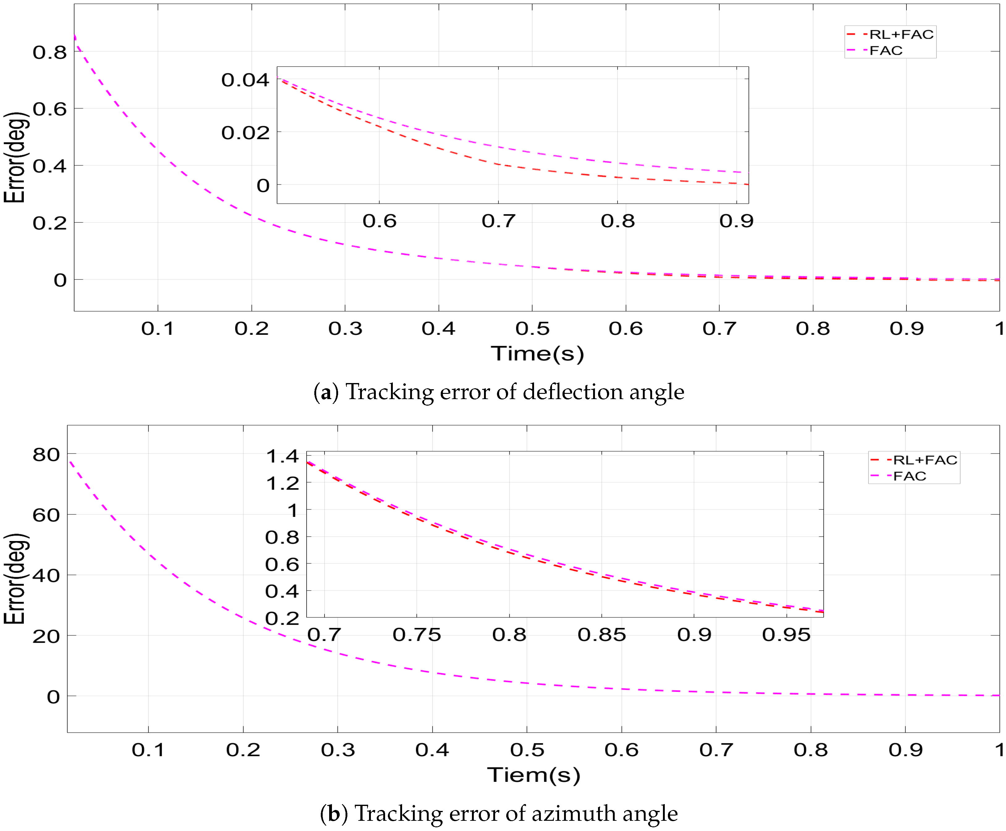
Test 1: The target deviation angle and target azimuth angle are constant. Figure 6 shows the error in tracking the target pointing angle, and Figure 7 shows the absolute error integral during the tracking process. Both methods can converge the root error to near zero and remain stable in a short time. However, RL+FAC converges faster because the reinforcement learning compensator can quickly identify and compensate for static errors in the system, thereby stabilizing the beam at the target position in a short period of time. The reduction in cumulative absolute error indicates that this method can reduce long-term drift, which is critical for maintaining a stable optical link in laser communications. In addition, the FAC method can converge the tracking error of the deflection angle to within 1.00 × 10 4 , while the FAC+RL method can converge the error to within 1.00 × 10 5 , reducing the steady-state error by 90 % . For azimuth, both methods can converge the error to within 1.00 × 10 6 .
Test 2 ∼ Test 3: Figure 8 and Figure 9 show the results of the target azimuth angle remaining constant while the deviation angle deviates within 0 ° 16 ° . The deviation angle tracking signal is 8 s i n ( 2 π t ) + 8 . Figure 10 and Figure 11 show the results of the target deviation angle remaining constant while the azimuth angle deviates within 0 ° 360 ° . The azimuth tracking signal is 360 s i n ( π t ) . In Test 2, for the deflection angle, the FAC method can converge the tracking error to within 1.00 × 10 2 , while the FAC+RL method can converge the tracking error to within 1.00 × 10 4 , representing a two-order-of-magnitude improvement. For the azimuth angle, the FAC method converges the tracking error to within 0.21 , while the FAC+RL method converges the tracking error to within 0.19 , reducing the steady-state error by 9.52 % . In Test 3, for the deflection angle, the FAC method can converge the tracking error to within 8.00 × 10 7 , while the FAC+RL method can converge the tracking error to within 5.00 × 10 7 , reducing the steady-state error by 37.5 % . For the azimuth angle, the FAC method converges the tracking error to within 3.00 × 10 2 , while the FAC+RL method converges the tracking error to within 2.00 × 10 2 , reducing the steady-state error by 33.3 % . The results show that when the azimuth angle or deflection angle changes independently, the cumulative error of RL+FAC is smaller. This is due to the real-time learning of the compensator for nonlinear mapping: there is a complex trigonometric relationship between the prism rotation angle and the beam direction (Equations (1)–(7)). RL learns and compensates through low-dimensional FAC output, effectively suppressing the nonlinearity of the system.
Test 4 ∼ Test 5: The target deviation angle and azimuth angle move within a certain range. Figure 12 and Figure 13 show the effect of the azimuth angle moving within 20 ° 220 ° and the deviation angle moving within 0 ° 16 ° . The azimuth angle tracking signal is 100 s i n ( π t ) + 120 , and the deviation angle tracking signal is 8 s i n ( 2 π t ) + 8 . Figure 14 and Figure 15 show the effect of the azimuth angle and the deviation angle simultaneously moving near the limit range. The azimuth angle moves within 0 ° 360 ° , while the deviation angle moves within 0 ° 16 ° . The azimuth angle tracking signal is 360 s i n ( π t ) , and the deviation angle tracking signal is 8 s i n ( 2 π t ) + 8 . In Test 4, for the deflection angle, the FAC method can converge the tracking error to within 4.00 × 10 6 , while the FAC+RL method can converge the tracking error to within 3.00 × 10 6 , reducing the steady-state error by 25 % . For the azimuth angle, the FAC method converges the tracking error to within 0.15 , while the FAC+RL method converges the tracking error to within 0.1 , reducing the steady-state error by 33.3 % . In Test 5, for the deflection angle, the FAC method can converge the tracking error to within 0.01 , while the FAC+RL method can converge the tracking error to within 1.00 × 10 3 , reducing the steady-state error by 90 % . For the azimuth angle, the FAC method converges the tracking error to within 0.03 , while the FAC+RL method converges the tracking error to within 0.01 , reducing the steady-state error by 66.67 % . From the results, it can be seen that reinforcement learning can effectively compensate for the controller, enabling the compensated RL+FAC method to maintain faster convergence speed, higher control accuracy and smaller cumulative error, both within a certain range of deflection and near the limit angle range. It is noted that the enlarged illustration in Figure 12a shows some transient rises or falls, which occur when the tracking trajectory reaches the maximum deflection angle. Taking the deflection angle as an example, the target signal is 8 s i n ( 2 π t ) + 8 , which reaches a maximum value at t = 1.75 s. This position corresponds to the region where the Risley prism system exhibits its strongest nonlinearity, making control more challenging. This jitter arises from the interaction between the FAC controller and the inherent strong nonlinearity of the Risley prism system, akin to introducing a significant internal disturbance into the control loop. This is precisely the manifestation of the FAC’s ability to suppress nonlinearity.
Test 6: Change the prism parameters for the experiment, change the index of refraction to n = 1.78 , and change the prism wedge angle to α = 10 ° . The azimuth angle moves within 0 ° 360 ° , and the deviation angle moves within 0 ° 12 ° . Figure 16 and Figure 17 show the experimental results. In Test 6, for the deflection angle, the FAC method converges the tracking error to within 3.00 × 10 6 , while the FAC+RL method converges the tracking error to within 2.00 × 10 6 , reducing the steady-state error by 33.3 % . For the azimuth angle, the FAC method converges the tracking error to within 0.04 , while the FAC+RL method converges the tracking error to within 0.02 , reducing the steady-state error by 50 % . The results show that even when the prism parameters are changed, causing changes in the system parameters, reinforcement learning can still effectively compensate for the control system, and RL+FAC still has a smaller overall error. This proves that the method is robust and does not rely on accurate models and can compensate for changes in optical characteristics caused by differences in prism manufacturing through online learning.
Regarding the stability and convergence analysis of the proposed FAC+RL method, a detailed theoretical proof based on Lyapunov stability theory has been provided in Section 3.3. To further evaluate the practical repeatability and robustness of the algorithm, we conducted 10 repeated tracking experiments under the same conditions. The average value of the integrated absolute error (IAE) was calculated, with the results shown in Table 3. The statistical results indicate that the FAC+RL method exhibits lower cumulative error in all tests. This not only demonstrates that the method can improve the control accuracy of the system but also highlights the excellent repeatability and reliability of the proposed method.
Based on the above experiments, the fully actuated control method based on reinforcement learning outperformed ordinary fully actuated control in all tests. The reinforcement learning compensator designed in this paper uses the error and the FAC control amount before compensation as observations and uses the relative error with FAC as the reward function for strategy learning. Through the Actor–Critic network, the control strategy is dynamically adjusted, and dynamic compensation is performed based on the FAC method to predictively suppress nonlinear coupling effects, which can further reduce model errors. It also has a good compensation effect at positions where the beam deviation angle is large, which is where the nonlinearity is most significant. At the same time, the fully actuated controller output can be used as a low-dimensional observation signal to a certain extent as prior knowledge for reinforcement learning, alleviating the problem of high convergence training complexity.
There are also other control studies based on the Risley prism, such as the robust control method proposed by Ma et al. [24] based on an extended state observer. This method is fundamentally model-driven, with its core lying in precisely estimating and real-time compensating for total disturbances in the system through a linear observer. This is an efficient and mature reactive compensation scheme that can effectively reduce peak errors. However, its performance ceiling is limited by the accuracy of the offline-established mathematical model and the inherent strong nonlinearity exhibited by the Risley prism near its maximum deflection angle. The method proposed in this paper adopts a data-driven reinforcement learning (RL) architecture that does not rely on precise prior models. Instead, it actively learns the system’s nonlinear dynamics and disturbance patterns through online interaction, thereby generating predictive feedforward compensation signals. This means that for regular nonlinear behavior, the RL agent can learn and anticipate its impact rather than suppressing it after it causes errors. The goal is to optimize accuracy based on high-performance fully actuated control. The composite axis control system proposed by Xia et al. [41], based on the Risley prism and fast control mirror (FSM), provides an efficient solution to the contradiction between tracking accuracy and response speed from a system architecture perspective. It uses the FSM’s high bandwidth to suppress high-frequency disturbances and feeds the FSM deflection angle back to the Risley prism for collaborative compensation, ultimately achieving ultra-high tracking accuracy at the sub-arcsecond level. Unlike the core approach of this study, this work represents an increase in system performance through increased hardware. In contrast, the RL+FAC control strategy studied in this paper deeply explores the performance potential of the existing single Risley prism hardware architecture through data-driven reinforcement learning algorithms without altering the hardware architecture. The former demonstrates significant advantages in terms of absolute accuracy metrics but introduces higher system complexity and cost; the latter focuses on enhancing system performance by intelligently compensating for nonlinearities and disturbances within a single Risley system architecture.

5. Conclusions

High-precision pointing control of the beam is one of the key technologies in fields such as laser communication. This paper proposes a fully actuated control method based on reinforcement learning compensation for nonlinear control problems in Risley prism systems. This method combines fully actuated control theory with reinforcement learning methods: reinforcement learning methods are based on Actor–Critic networks, which further estimate model nonlinearity and uncertainty to compensate for the controller and improve control performance. At the same time, the output and error information of the fully actuated controller are used as reinforcement learning observations to reduce learning complexity. This method takes advantage of the strengths of both methods in dealing with nonlinear problems while alleviating the difficulties of insufficient control accuracy and complex convergence of reinforcement learning in fully actuated control methods. The stability of the method is verified through detailed theoretical analysis. Finally, the fully actuated control method based on reinforcement learning compensation is verified experimentally to have smaller cumulative error, faster convergence speed, and higher accuracy.

Author Contributions

Conceptualization, M.X. and J.W.; Methodology, R.X.; Software, H.X.; Validation, F.W.; Investigation, J.W.; Writing—original draft, R.X. and H.X.; Writing—review & editing, R.X.; Supervision, F.W.; Project administration, M.X. All authors have read and agreed to the published version of the manuscript.

Funding

This research was funded by the Leading Talent Project of the Sanqin Scholars Special Support Program of Shaanxi Province.

Data Availability Statement

Data are contained within the article.

Conflicts of Interest

The authors declare no conflicts of interest.

References

  1. Wang, X.; Han, J.; Wang, C.; Xie, M.; Liu, P.; Cao, Y.; Jing, F.; Wang, F.; Su, Y.; Meng, X. Beam Scanning and Capture of Micro Laser Communication Terminal Based on MEMS Micromirrors. Micromachines 2023, 14, 1317. [Google Scholar] [CrossRef] [PubMed]
  2. Gao, D.; Sun, M.; He, M.; Jia, S.; Xie, Z.; Yao, B.; Wang, W. Development current status and trends analysis of deep space laser communication (cover paper·invited). Hongwai Yu Jiguang Gongcheng/Infrared Laser Eng. 2024, 53, 20240247. [Google Scholar]
  3. Xu, X.; Xu, L.; Liang, X.; Dai, J. Multi-Beam Focusing and Deflecting Characteristics of Liquid Crystal Optical Phased Array. Photonics 2025, 12, 181. [Google Scholar] [CrossRef]
  4. Galaktionov, I.; Toporovsky, V.; Nikitin, A.; Rukosuev, A.; Alexandrov, A.; Sheldakova, J.; Laskin, A.; Kudryashov, A. Software and hardware implementation of the algorithm for 2-mirrors automatic laser beam alignment system. In Laser Beam Shaping XXIII; The Society of Photo–Optical Instrumentation Engineers (SPIE): San Diego, CA, USA, 2023; Volume 12667, pp. 111–115. [Google Scholar]
  5. Zhang, X.; Dai, W.J.; Wang, Y.C.; Lian, B.; Yang, Y.; Yuan, Q.; Deng, X.W.; Zhao, J.P.; Zhou, W. Automatic alignment technology in high power laser system. In Proceedings of the XX International Symposium on High-Power Laser Systems and Applications 2014, Chengdu, China, 25–29 August 2014; Volume 9255, pp. 862–865. [Google Scholar]
  6. Burkhart, S.C.; Bliss, E.; Nicola, P.D.; Kalantar, D.; Lowe-Webb, R.; McCarville, T.; Nelson, D.; Salmon, T.; Schindler, T.; Villanueva, J.; et al. National Ignition Facility system alignment. Appl. Opt. 2011, 50, 1136–1157. [Google Scholar] [CrossRef]
  7. Lahari, S.A.; Raj, A.; Soumya, S. Control of fast steering mirror for accurate beam positioning in FSO communication system. In Proceedings of the 2021 International Conference on System, Computation, Automation and Networking (ICSCAN), Puducherry, India, 30–31 July 2021. [Google Scholar]
  8. Garcia-Torales, G. Risley prisms applications: An overview. Adv. 3OM Opto-Mechatronics Opto-Mech. Opt. Metrol. 2021, 12170, 136–146. [Google Scholar] [CrossRef]
  9. Ostaszewski, M.; Harford, S.; Doughty, N.; Huffman, C.; Sanchez, M.; Gutow, D.; Pierce, R. Risley prism beam pointer. In Free-Space Laser Communications VI; SPIE: Denver, CO, USA, 2006; Volume 6304. [Google Scholar] [CrossRef]
  10. Sun, J.; Liu, L.; Yun, M.; Wang, L.; Xu, N. Double prisms for two-dimensional optical satellite relative-trajectory simulator. In Free-Space Laser Communications IV; SPIE: Denver, CO, USA, 2004; Volume 5550, pp. 411–418. [Google Scholar]
  11. Li, A.; Yi, W.; Sun, W.; Liu, L. Tilting double-prism scanner driven by cam-based mechanism. Appl. Opt. 2015, 54, 5788–5796. [Google Scholar] [CrossRef]
  12. Shen, Y.; Li, L.; Huang, F.; Ren, H.; Liu, J. Pointing Error Correction of Risley-Prism System Based onParticle Swarm Algorithm. Acta Opt. Sin. 2021, 41, 139–148. [Google Scholar]
  13. Li, Y. Third-order theory of the Risley-prism-based beam steering system. Appl. Opt. 2011, 50, 679–686. [Google Scholar] [CrossRef]
  14. Li, Y. Ruled surfaces generated by Risley prism pointers: I. Pointing accuracy evaluation and enhancement based on a structural analysis of the scan field inside the pointer. J. Opt. Soc. Am. A 2021, 38, 1884–1892. [Google Scholar] [CrossRef]
  15. Li, Y. Risley prisms as a conformal transformation device. I. Complex and graphic analyses of mapping images conformality. J. Opt. Soc. Am. A 2022, 39, 1540–1548. [Google Scholar] [CrossRef] [PubMed]
  16. Li, Y. Risley prisms as a conformal transformation device: II. Derivatives of the absolute functions and an attributive analysis of the control singularities. J. Opt. Soc. Am. A 2022, 39, 1549–1557. [Google Scholar] [CrossRef] [PubMed]
  17. Li, J.; Chen, K.; Peng, Q.; Wang, Z.; Jiang, Y.; Fu, C.; Ren, G.; Li, A.; Sun, W.; Liu, X.; et al. Improvement of pointing accuracy for Risley prisms by parameter identification. Appl. Opt. 2017, 56, 7358–7366. [Google Scholar] [CrossRef]
  18. Li, J.Y.; Peng, Q.; Chen, K.; Fu, C.Y. High precision pointing system based on Risley prism: Analysis and simulation. In Proceedings of the XX International Symposium on High-Power Laser Systems and Applications 2014, Chengdu, China, 25–29 August 2015; Volume 9255, pp. 323–329. [Google Scholar]
  19. Zhou, Y.; Lu, Y.; Hei, M.; Liu, G.; Fan, D. Motion control of the wedge prisms in Risley-prism-based beam steering system for precise target tracking. Appl. Opt. 2013, 52, 2849–2857. [Google Scholar] [CrossRef]
  20. Zhou, Y.; Lu, Y.; Hei, M.; Liu, G.; Fan, D. Pointing error analysis of Risley-prism-based beam steering system. Appl. Opt. 2014, 53, 5775–5783. [Google Scholar] [CrossRef]
  21. Zhou, Y.; Fan, S.; Chen, Y.; Zhou, X.; Liu, G. Beam steering limitation of a Risley prism system due to total internal reflection. Appl. Opt. 2017, 56, 6079–6086. [Google Scholar] [CrossRef]
  22. Zhou, Y.; Chen, Y.; Zhu, P.; Jiang, G.; Hu, F.; Fan, S. Limits on field of view for Risley prisms. Appl. Opt. 2018, 57, 9114–9122. [Google Scholar] [CrossRef]
  23. Zhou, Y.; Chen, Y.; Sun, L.; Zou, Z.; Zou, Y.; Chen, X.; Fan, S.; Fan, D. Singularity Problem Analysis of Target Tracking Based on Risley Prisms. Acta Opt. Sin. 2025, 45, 133–143. [Google Scholar]
  24. Ma, R.; Wang, Q.; Li, J.; Xia, Y.; Yuan, L.; Yuan, J.; Shi, J.; Liu, X.; Tu, Q.; Tang, T.; et al. Robust Risley prism control based on disturbance observer for system line-of-sight stabilization. Appl. Opt. 2022, 61, 3463–3472. [Google Scholar] [CrossRef]
  25. Yuan, L.; Li, J.; Fan, Y.; Shi, J.; Huang, Y. Enhancing pointing accuracy in Risley prisms through error calibration and stochastic parallel gradient descent inverse solution method. Precis. Eng. 2025, 93, 37–45. [Google Scholar] [CrossRef]
  26. Yuan, L.; Huang, Y.; Fan, Y.; Shi, J.; Xia, H.; Li, J. Rotational Risley prisms: Fast and high-accuracy inverse solution and application based on back propagation neural networks. Measurement 2025, 242, 116007. [Google Scholar] [CrossRef]
  27. Garcia-Torales, G.; Flores, J.L.; Munoz, R.X. High precision prism scanning system. In Sixth Symposium: Optics in Industry; SPIE: Monterrey, Mexico, 2007; Volume 6422. [Google Scholar] [CrossRef]
  28. Yuxiang, Y.; Ke, C.; Jinying, L.; Congming, Q. Closed-Loop Control of Risley Prism Based on Deep Reinforcement Learning. In Proceedings of the 2020 International Conference on Computer Engineering and Application, Guangzhou, China, 27–29 March 2020; pp. 481–488. [Google Scholar]
  29. Gu, S.; Holly, E.; Lillicrap, T.; Levine, S. Deep reinforcement learning for robotic manipulation with asynchronous off-policy updates. In Proceedings of the 2017 IEEE International Conference on Robotics and Automation (ICRA), Singapore, 29 May–3 June 2017; pp. 3389–3396. [Google Scholar] [CrossRef]
  30. Li, Y. Closed form analytical inverse solutions for Risley-prism-based beam steering systems in different configurations. Appl. Opt. 2011, 50, 4302–4309. [Google Scholar] [CrossRef] [PubMed]
  31. Duan, G.; Zhou, B.; Yang, X. Fully actuated system theory and applications: New developments in 2023. Int. J. Syst. Sci. 2024, 55, 2419–2420. [Google Scholar] [CrossRef]
  32. Duan, G. High-order fully actuated system approaches: Part I. Models and basic procedure. Int. J. Syst. Sci. 2021, 52, 422–435. [Google Scholar] [CrossRef]
  33. Duan, G. High-order fully actuated system approaches: Part II. Generalized strict-feedback systems. Int. J. Syst. Sci. 2021, 52, 437–454. [Google Scholar] [CrossRef]
  34. Agostinelli, F.; Hocquet, G.; Singh, S.; Baldi, P. From Reinforcement Learning to Deep Reinforcement Learning: An Overview. In Braverman Readings in Machine Learning: Key Ideas from Inception to Current State; Lecture Notes in Artificial, Intelligence; Rozonoer, L., Mirkin, B., Muchnik, I., Eds.; Springer: Cham, Switzerland, 2018; Volume 11100, pp. 298–328. [Google Scholar] [CrossRef]
  35. Tan, F.; Yan, P.; Guan, X. Deep Reinforcement Learning: From Q-Learning to Deep Q-Learning. In Proceedings of the Neural Information Processing (ICONIP 2017), PT IV, Guangzhou, China, 14–18 November 2017; Liu, D., Xie, S., Li, Y., Zhao, D., ElAlfy, E., Eds.; Volume 10637, pp. 475–483. [Google Scholar] [CrossRef]
  36. Lyu, L.; Shen, Y.; Zhang, S. The Advance of Reinforcement Learning and Deep Reinforcement Learning. In Proceedings of the 2022 IEEE International Conference on Electrical Engineering, Big Data and Algorithms (EEBDA), Changchun, China, 25–27 February 2022; pp. 644–648. [Google Scholar] [CrossRef]
  37. Duan, G.R. Fully Actuated System Approach for Control: An Overview. IEEE Trans. Cybern. 2024, 54, 7285–7306. [Google Scholar] [CrossRef] [PubMed]
  38. Duan, G. High-order fully actuated system approaches: Part III. Robust control and high-order backstepping. Int. J. Syst. Sci. 2021, 52, 952–971. [Google Scholar] [CrossRef]
  39. Xu, J.; Zhang, H.; Qiu, J. A deep deterministic policy gradient algorithm based on averaged state-action estimation. Comput. Electr. Eng. 2022, 101, 108015. [Google Scholar] [CrossRef]
  40. Tsitsiklis, J.; Van Roy, B. An analysis of temporal-difference learning with function approximation. IEEE Trans. Autom. Control 1997, 42, 674–690. [Google Scholar] [CrossRef]
  41. Xia, H.; Xia, Y.; Yuan, L.; Wen, P.; Zhang, W.; Ding, K.; Fan, Y.; Ma, H.; Li, J. Fast and high-precision tracking technology for image-based closed-loop cascaded control system with a Risley prism and fast steering mirror. Opt. Express 2024, 32, 8555–8571. [Google Scholar] [CrossRef] [PubMed]
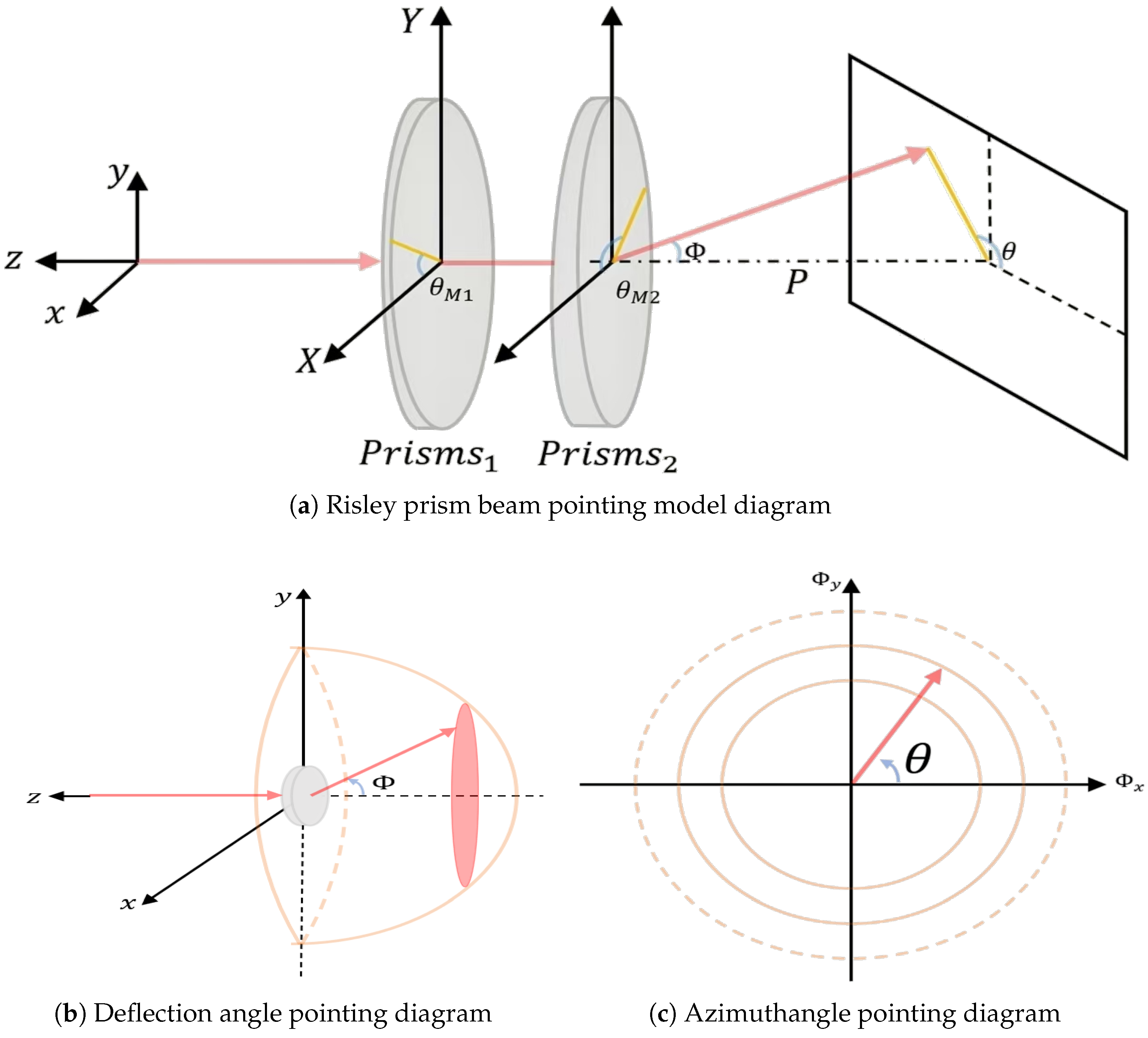
Figure 1. Schematic diagram of the Risley prism beam pointing.
Photonics 12 00885 g001
Figure 2. Risley prism beam control model system block Diagram.
Photonics 12 00885 g002
Figure 3. Overall block diagram of reinforcement learning compensatory-based fully actuated control method for a Risley prism.
Photonics 12 00885 g003
Figure 4. Angular velocity tracking results for high-speed signals. The main image is in the upper right corner, surrounded by sub-images that are enlarged sections of the main image. It is important to note that, in order to keep the overall image simple, the coordinate axis information has been removed from the sub-images, but the coordinate axis information of the sub-images is completely consistent with that of the main image.
Photonics 12 00885 g004
Figure 5. Angular velocity tracking results for low-speed signals. The main image is in the upper right corner, surrounded by sub-images that are enlarged sections of the main image. It is important to note that, in order to keep the overall image simple, the coordinate axis information has been removed from the sub-images, but the coordinate axis information of the sub-images is completely consistent with that of the main image.
Photonics 12 00885 g005
Figure 6. Error results for deflection and azimuth angles in Test 1.
Photonics 12 00885 g006
Figure 7. Integrated absolute error results for deflection and azimuth angles in Test 1.
Photonics 12 00885 g007
Figure 8. Error results for deflection and azimuth angles in Test 2.
Photonics 12 00885 g008
Figure 9. Integrated absolute error results for deflection and azimuth angles in Test 2.
Photonics 12 00885 g009
Figure 10. Error results for deflection and azimuth angles in Test 3.
Photonics 12 00885 g010
Figure 11. Integrated absolute error results for deflection and azimuth angles in Test 3.
Photonics 12 00885 g011
Figure 12. Error results for deflection and azimuth angles in Test 4.
Photonics 12 00885 g012
Figure 13. Integrated Absolute error results for deflection and azimuth angles in Test 4.
Photonics 12 00885 g013
Figure 14. Error results for deflection and azimuth angles in Test 5.
Photonics 12 00885 g014
Figure 15. Integrated absolute error results for deflection and azimuth angles in Test 5.
Photonics 12 00885 g015
Figure 16. Error results for deflection and azimuth angles in Test 6.
Photonics 12 00885 g016
Figure 17. Integrated absolute error results for deflection and azimuth angles in Test 6.
Photonics 12 00885 g017
Table 1. System model parameters.
ParametersMeaningValue
B D a m p i n g   c o e f f i c i e n t  (N·m·s/rad) 6.5 × 10 4
R a A r m a t u r e   r e s i s t a n c e   ( Ω ) 1
J T o t a l   m o m e n t   o f   i n e r t i a  (kg·m2) 4.5 × 10 4
K e D a m p i n g   c o e f f i c i e n t  (N·m·s/rad) 0.12
K t B a c k   E M F   c o n s t a n t  (V·s/rad) 0.12
n I n d e x   o f   R e f r a c t i o n 1.51
α W e d g e   A n g l e   ( deg ) 16
Table 2. Risley prism control test information.
TestDeviation Deflection RangeAzimuthal Deflection Range
Test 1 ( n = 1.51 , α = 16 ) 10 ° 100 °
Test 2 ( n = 1.51 , α = 16 ) 0 ° –16°80°
Test 3 ( n = 1.51 , α = 16 ) 8 ° 0 ° –360°
Test 4 ( n = 1.51 , α = 16 ) 0 ° –16° 20 ° –220°
Test 5 ( n = 1.51 , α = 16 ) 0 ° –16° 0 ° –360°
Test 6 ( n = 1.78 , α = 10 ) 0 ° –12° 0 ° –360°
Table 3. The average value of the integrated absolute error of 10 repeated experiments.
IAE of Deflection Angle (deg)IAE of Azimuth Angle (deg)
TestFACFAC+RLFACFAC+RL
Test 10.37430.342916.953415.8186
Test 20.12900.116113.684013.1700
Test 30.04360.03852.13701.9340
Test 40.14230.138321.209320.1940
Test 50.13080.12142.13941.9322
Test 60.08440.07362.51332.3081
Disclaimer/Publisher’s Note: The statements, opinions and data contained in all publications are solely those of the individual author(s) and contributor(s) and not of MDPI and/or the editor(s). MDPI and/or the editor(s) disclaim responsibility for any injury to people or property resulting from any ideas, methods, instructions or products referred to in the content.