Article

Reconfigurable All-Optical Synapse Based on Photonic Crystal Nanobeam Cavities with Ferroelectric Carrier Injection Valve

1
State Key Laboratory of Wide-Bandgap Semiconductor Devices and Integrated Technology, Faculty of Integrated Circuits, Xidian University, Xi’an 710071, China
2
Research Institute of Sun Yat-sen University in Huizhou, Huizhou 516081, China
3
Beijing Smartchip Microelectronics Technology Co., Ltd., Beijing 102299, China
*
Author to whom correspondence should be addressed.
Photonics 2025, 12(9), 871; https://doi.org/10.3390/photonics12090871
Submission received: 23 July 2025 / Revised: 24 August 2025 / Accepted: 27 August 2025 / Published: 29 August 2025
(This article belongs to the Special Issue Silicon Photonics: From Fundamentals to Future Directions)

Abstract

Synaptic activity is fundamental to memory and learning in the nervous system. However, most artificial synaptic devices are limited to mimicking static plasticity, and tunable plasticity has not been achieved at the device level. Here, we introduce a dynamic all-optical synapse based on photonic crystal nanobeam cavities with a ferroelectric carrier injection valve. By leveraging the nonlinear and ferroelectric electrostatic doping effects in silicon, integrated with Hf0.5Zr0.5O2 (HZO) film as the ferroelectric layer and indium tin oxide (ITO) as the top electrode, we enhance linearity and reduce power consumption. Increasing the bias voltage further improves linearity while decreasing power consumption. This innovation offers a promising pathway for developing energy-efficient nanophotonic devices in neuromorphic computing.

1. Introduction

In recent years, neuromorphic computing has received a lot of interest for its potential to overcome the limitations of traditional von Neumann architectures, particularly in artificial intelligence (AI) applications involving deep learning algorithms [1]. Synapses are fundamental to brain computation and memory, supporting cognitive functions such as consciousness, emotions, and behavior [2,3,4]. The rapid advancement of AI has outpaced the capabilities of electronic processors in terms of computational throughput, information capacity, and processing speed [5]. Optical processors, which use photons for computation, offer advantages such as high bandwidth, connectivity, low power consumption, and low latency, making them suitable for addressing these challenges [6]. However, photonic synaptic devices face issues with non-linear weight updates and higher power consumption compared to electrically stimulated synapses [7]. Traditional photonic synapses based on micro-ring resonator (MRR) are limited by channel count and device size [8]. In contrast, photonic crystals provide advantages such as strong optical confinement, small mode volume, and small footprint, making them applicable in many areas of physics and engineering [9]. Based on 2D photonic crystal resonators, such as photonic crystal cavities and ring resonators, re-locatable photonic crystal resonators [10] have been applied in all-optical decoders [11], modulators [12], and other related fields. One-dimensional photonic crystal nanobeam cavity (PCNBC) offer advantages such as increased channel capacity, efficient coupling with optical waveguides, enhanced light-matter interaction, and compatibility with CMOS processes [13,14]. Most importantly, compared to 2D photonic crystal resonators, it has a smaller footprint, making it ideal for on-chip integration. PCNBC-based devices have been used as electro-optic modulators [15] and wavelength filters [16]. For photonic synapses, device size significantly impacts energy consumption for weight adjustments and computing density, with smaller devices offering higher efficiency [17]. Recently, nonlinear phenomena such as two-photon absorption (TPA), TPA-induced free carrier absorption (FCA), and the Kerr effect have been extensively studied in silicon high-Q PCNBC [18]. Our group has previously reported related achievements in this area [19]. However, the nonlinear effects in Si-based nanobeam cavities can be detrimental to synapses requiring linear weighting functions.
Ferroelectrics have been considered as candidates for performing neural network operations and simulating artificial synaptic devices due to their nonvolatile multilevel memory effects. Ferroelectric neuron utilizes electric field to control ferroelectric polarization, which greatly reduces the energy consumption and modulation time, so that it can be used in efficient neural networks [20,21]. By using electric fields to control ferroelectric polarization, these materials enable low-energy and fast modulation, suitable for efficient neural networks. Through the integration of ferroelectrics with PCNBC, a new type of optoelectronic synaptic device can be achieved.
In this work, we introduce a ferroelectric-integrated optical neural device within a PCNBC architecture. The structure employs low-doped silicon as the cavity material with Hf0.5Zr0.5O2 (HZO) serving as the ferroelectric doping layer and indium tin oxide (ITO) as the top electrode. We develop a prediction method combining finite element simulations and analytical calculations, demonstrating enhanced linearity in synaptic weighting. By adjusting the applied writing voltage, we optimize linearity that directly improves neural network recognition accuracy. This ferroelectric optical synapse represents a compelling platform for energy-efficient neuromorphic photonics.

2. Device Design and Prediction Methodology

2.1. Device Design

The ferroelectric optical synaptic device, depicted in Figure 1a, consists of a silicon bus waveguide, a silicon nanobeam cavity, a ferroelectric layer, ITO electrodes, and a bottom electrode. To minimize optical losses, the p-type silicon is lightly doped at 1014 cm−3, while the ITO layer is heavily doped at 1018 cm−3 to function as a conductive layer. The ITO electrodes are positioned at the second resonance peaks of the nanobeam cavity for optimal ferroelectric modulation. The bottom electrodes are placed at the two extremities of the top surface of nanobeam cavity to prevent overlap with the optical mode. The fabrication process is designed for compatibility with standard semiconductor processes. It begins with patterning and etching a silicon waveguide into a silicon-on-insulator (SOI) substrate, followed by the deposition of an HZO ferroelectric film using atomic layer deposition (ALD). ALD faces several challenges as: a rough silicon surface can create an interface defect, increasing optical loss and weakening HZO’s ferroelectric property. Moreover, HZO requires annealing for crystallization, and high temperatures may damage the silicon waveguide, while low temperatures yield small grains and more amorphous phase, reducing ferroelectric performance. Non-uniform film thickness can lead to inconsistent ferroelectric performance. The top ITO layer is added through magnetron sputtering, and the structure is completed by patterning the photonic crystal holes and waveguides. The x-z cross-section, shown in Figure 1b, illustrates the vertical stacking of the polysilicon nanobeam cavity, HZO layer, and ITO layer. The HZO and ITO layers, each with a thickness of 10 nm, a length of 500 nm, and a width of 600 nm, are positioned on both sides of the silicon. The coupling gap between the waveguide and nanobeam cavity is optimized at 150 nm to maximize energy transfer while avoiding over-coupling. The silicon waveguide has a thickness of 220 nm and a width of 500 nm. The electrode configuration is consistent with previous work [22].
To achieve a high quality factor (Q) to mode volume (V) ratio, the bandgap-tapering technique is employed [23]. The nanobeam design includes three-hole mirror sections at both ends and a seven-segment tapered section with 14 holes at the center. The hole-to-hole distance, denoted as period a, and the filling ratio f, defined as the ratio of hole radius R to a, are carefully controlled. The mirror segments have a period of 420 nm and a filling ratio of 0.28. In the tapered region, the filling ratio R/a is fixed, while the period decreases linearly from a to 0.72a. The nanobeam cavity, with a width of 500 nm, is designed with minimal length to reduce scattering losses. The optimal values of above parameters were obtained by means of simulations, in which their respective effects on the Q were carefully analyzed and used as the basis for structural optimization. Employing high accuracy techniques, such as electron-beam lithography (EBL), can reduce the effects of fabrication tolerances arising from the extremely small structural dimensions, thereby reducing spectral shifts caused by it.
The signal and pump lights are axially incident into the mode field converter (MFC) through a standard single-mode fiber (SFC). And the incident wavelength is determined by the resonance wavelength of the PCNBC, while the power is adjusted according to simulation requirements. As butt coupling is adopted, the incidence angle of the light source approaches 0°. Subsequently, light at specific wavelengths is coupled from the bus waveguide into the PCNBC evanescently, and finally light exits from the other end of the bus waveguide. Similarly to a micro-ring resonator, the transmission spectrum of our device exhibits a resonance dip. The electric field distributions of the fundamental and second-order modes are shown in Figure 1d,e, respectively, with the first mode serving as the signal channel and the second as the pump channel, consistent with prior research.
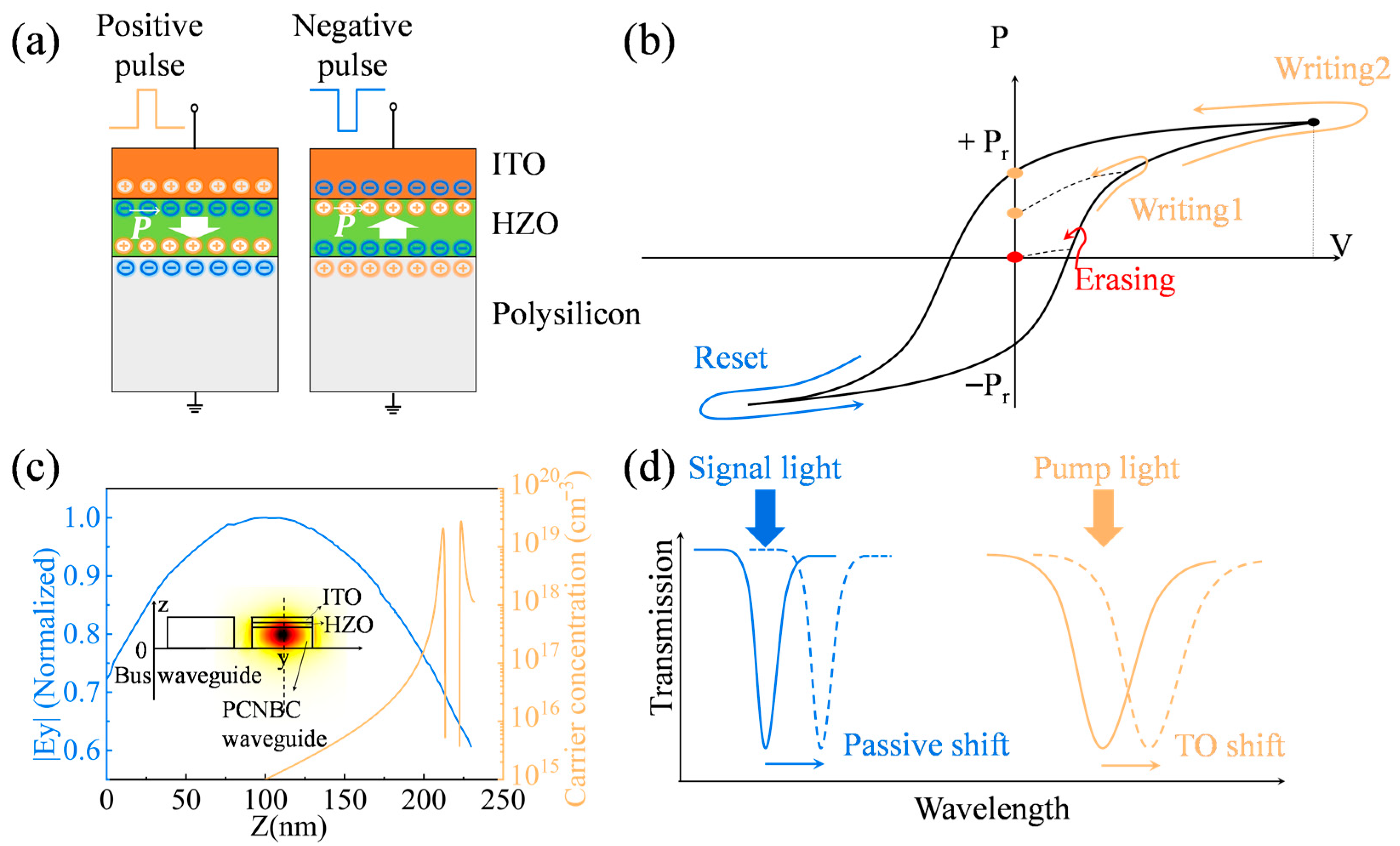
The device utilizes ferroelectric doping to change its optical properties, with HZO selected as the ferroelectric material due to its compatibility with silicon-based integrated circuit technology [24]. The principle of adjusting linearity by ferroelectric doping is shown in Figure 2. In the synaptic unit, the carrier distribution in silicon at reset is uniform along the z-axis. As illustrated in Figure 2a, a voltage pulse generates residual polarization charges that induce carrier aggregation at the HZO-silicon interface, persisting even after the voltage is removed. This enables a tunable residual charge range from 0 to Pr in both silicon and ITO, with a dynamic range of ∆Pr, as depicted in Figure 2b [25].
This ferroelectric doping mechanism is critical for non-volatile tuning of the optical properties of photonic crystal cavity, enabling synaptic weight adjustments in neuromorphic optical computing systems. Simulations using the semiconductor modules of COMSOL 6.0 reveal the carrier distribution in silicon. Figure 2c shows the electric field components |Ey| and carrier concentration along the dotted line of the first mode at a 4 V bias. The bias voltage redistributes the carrier concentration, separating the peak carrier density from the region of maximum optical field intensity, thus minimizing the impact on the signal light.
The plasma dispersion effect governs the changes in the optical refractive index (∆n) and extinction coefficient (∆k) of silicon, driven by the spatial redistribution of electrons and holes. The nonvolatile nature of the residual polarized charge ensures persistent modulation after power-down, enabling energy-efficient operation. Ferroelectric doping thus facilitates carrier redistribution, modulating the refractive index of the nanobeam cavity.
When pump light is coupled into the nanobeam cavity, it induces nonlinear spectral shifts due to optical nonlinear effects, including TPA, FCA, and the Kerr effect in high-Q silicon nanocavities. However, applying an appropriate voltage causes carriers in polysilicon to accumulate at the polysilicon-HZO interface due to ferroelectric doping, enhancing the thermo-optic (TO) effect. Previous studies indicate that the TO effect dominates spectral drift [20]. Consequently, carrier redistribution induced by polarized charges enables a linear spectral shift, critical for synaptic functionality.

2.2. Establishing a Prediction Methodology

In this section, we present a comprehensive prediction methodology that integrates finite element method (FEM) simulations with theoretical modeling to analyze and predict spectral drift in a nanobeam cavity. The spectral drift is primarily attributed to the TO effects and other nonlinear optical phenomena, including free carrier dispersion (FCD) and kerr effect both due to the photocarrier generated by TPA effect. The FEM simulation results were used to extract key parameters required for fitting theoretical prediction model. By substituting the extracted parameters into the temperature-dependent and wavelength-shift equations, we can establish the theoretical prediction model. Ultimately, the comparison between the simulation and theoretical results served to validate the accuracy of the proposed theory and demonstrate the feasibility of the overall scheme. The material parameters of ITO and HZO for constructing the finite element model are the same as the previous work.
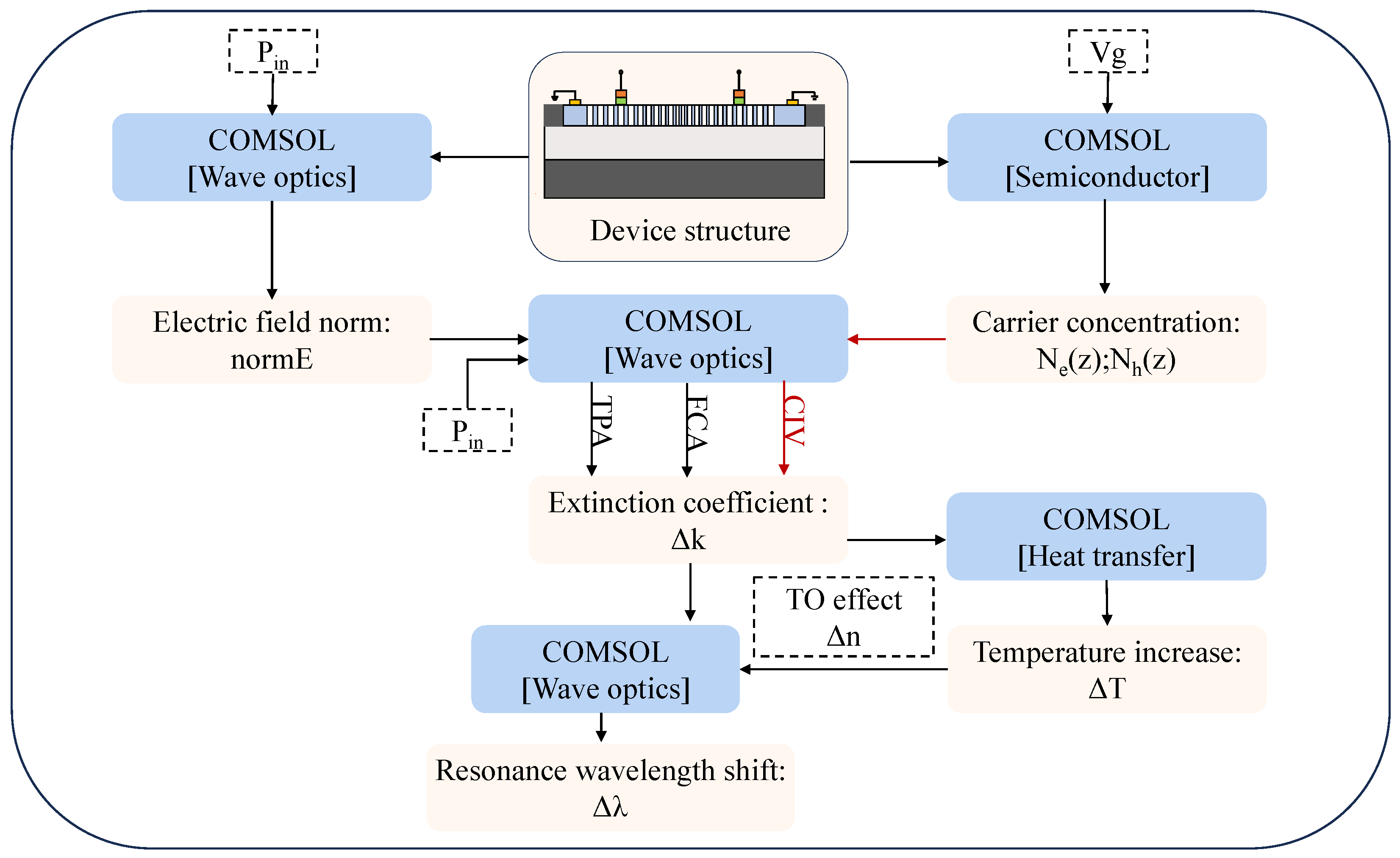
In order to present and validate our conjecture, multiple physical modules are involved, including solid state heat transfer, semiconductor, and wave optics modules. The workflow of our FEM simulation is illustrated in Figure 3. Initially, the nanobeam cavity structure is modeled in COMSOL. Subsequently, carrier concentration distributions under various applied bias voltages are simulated, and the electric field norm normE is calculated at the same time. Both of them are then used to compute the ∆k caused by carrier injection, TPA effect and the induced FCA effect. Due to the relatively large effective thermal resistance of the proposed PCNBC structure (calculated later in the article), the ∆n induced by the TO effect is much larger than that caused by FCD or the Kerr effect [19]. Therefore, their contributions were not considered in the simulations. In the experiments, a broadband light source can ensure the redshift caused by the TO effect does not alter normE. Moreover, the carrier concentration excited by thermal effect is negligible compared with that in doped silicon. Therefore, the thermo-optic effect has no significant impact on normE, carrier concentration, or ∆k in the simulations. Ultimately, combining the ∆k with the ∆n caused by TO effect, we can obtain the drift of the wavelength. In this simulation, environmental parameters were set to idealized values to focus on the device’s intrinsic performance.
The material parameters for ITO and HZO used in our FEM model are consistent with those reported in previous studies. Additionally, we use a verified domain wall model to fit the hysteresis property of HZO thin films, and the HZO thin films used this time are the same as the previous work [23]. The surface charge of the ferroelectric HZO is modeled as
Q F e = P F e + ε F e V a / t F e
where QFe is the total charge, PFe is the polarization charge, εFe and tFe are the permittivity and thickness of the ferroelectric film, respectively, and Va is the applied voltage. A stable voltage ensures complete polarization with residual charge PFe retained after voltage removal, varying with the applied voltage amplitude.
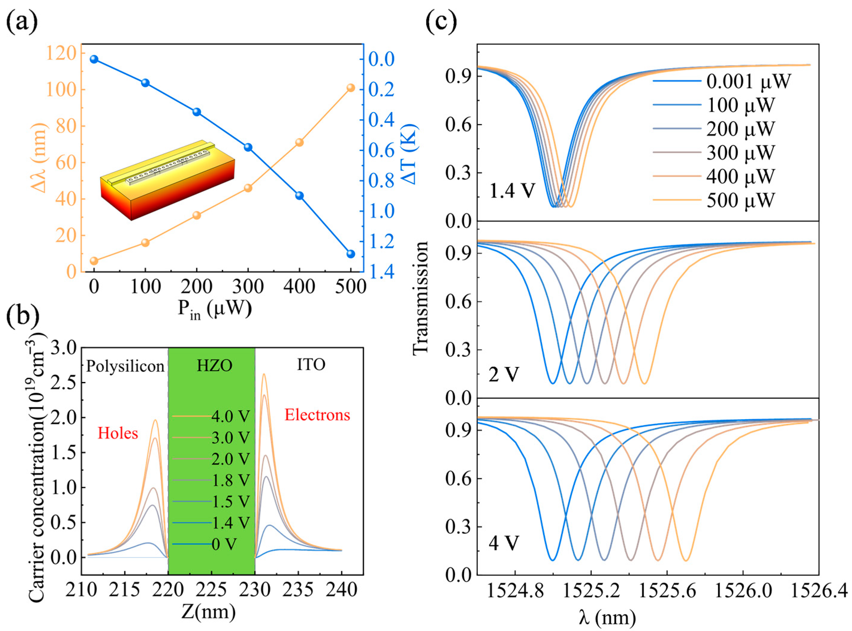
Our FEM simulations reveal that both the temperature increase and the resonance wavelength shift in the nanobeam cavity exhibit non-linear dependencies on the pump power, as depicted in Figure 4a for the reset state. Specifically, at a pump power of 500 μW, the temperature in the resonance region rises by 1.3 K, accompanied by a spectral drift. The application of bias voltages enhances the FCA effect at the silicon/HZO interface, leading to more pronounced TO effects and larger spectral shifts. As illustrated in Figure 4b, higher bias voltages result in increased carrier concentrations at the interface, thereby inducing greater spectral redshifts. Figure 4c presents the spectral drift as a function of pump power ranging from 0.001 μW to 500 μW, yielding drifts of 0.101 nm at reset, 0.49 nm at 2 V, and 0.68 nm at 4 V. Under both 2 V and 4 V biases, a good linear relationship is preserved as the power approaches zero. At 2 V, the effective upper limit of the linearity is 250 µW, and this limit increases with increasing bias. Since the linearity of the spectral drift improves with increasing bias voltage, suggesting that electrostatic doping can be leveraged to tune the device’s linearity.
To complement our simulation results, we develop a theoretical prediction model that accounts for the contributions of TPA, FCA, and TO effects to the spectral drift. The key parameters for this model are extracted from our FEM simulations. The main parameters used to build the analytical model are shown in Table 1. The temperature difference inside the cavity, ΔT, is modeled as
Δ T = R e f f ( τ T P A + τ F C A + τ C I V ) Q ( 1 K ) 1 2 P i n
where Reff is the effective thermal resistance, 1/τTPA, 1/τFCA and 1/τCIV are the decay times associated with TPA, FCA, and carrier injection, respectively, Q is the quality factor of the resonant mode, K is the transmission, and Pin is the input pump power. The spectral shifts due to TPA and FCA are both proportional to the square of the input power as
Δ λ T P A = P i n 2
Δ λ F C A = P i n 2
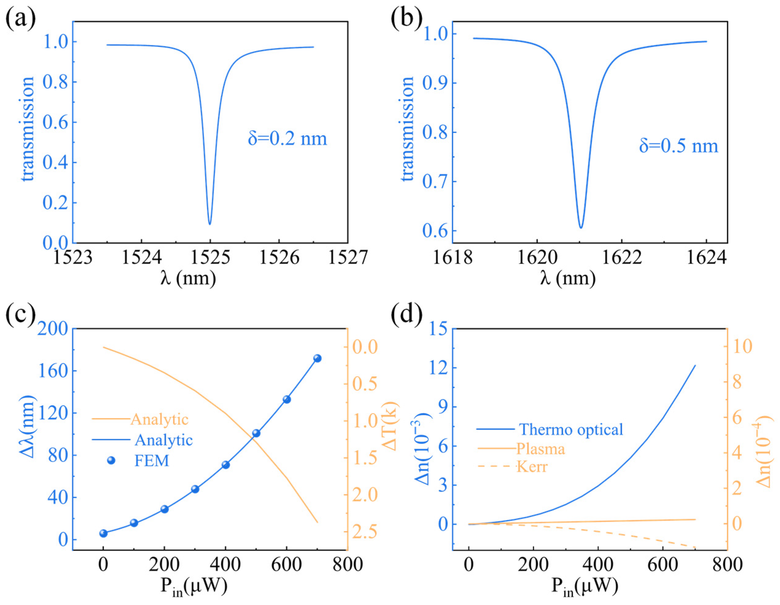
From our FEM simulations, we extract resonance wavelength 1525.00 nm of the first mode and the Q = 3217 and K = 0.61 for the second mode at 1621.06 nm in the reset state, as shown in Figure 5a,b. The energy decay rate for carrier injection is given by 1/τCIV = 4πkc/nsiλ, where c is the speed of light, nsi is the refractive index of silicon, λ is the resonant wavelength, and k is the change in the imaginary part of the refractive index due to carrier injection. Using these values, along with the resonance wavelength shift ∆λ and temperature difference ∆T as functions of pump power, we estimate the effective thermal resistance Reff to be 3880 K·mW−1, as shown in Figure 5c. Figure 5d illustrates the variation in the refractive index due to various effects, highlighting the dominance of TO effects.
Our theoretical model demonstrates that TO effects dominate the spectral drift, converting the energy absorbed via TPA, FCA and electrostatic doping into heat. By modulating the electrostatic doping through applied bias voltages, we can effectively control the TO response, thereby achieving tunable linearity in the spectral drift.

3. Results and Discussion

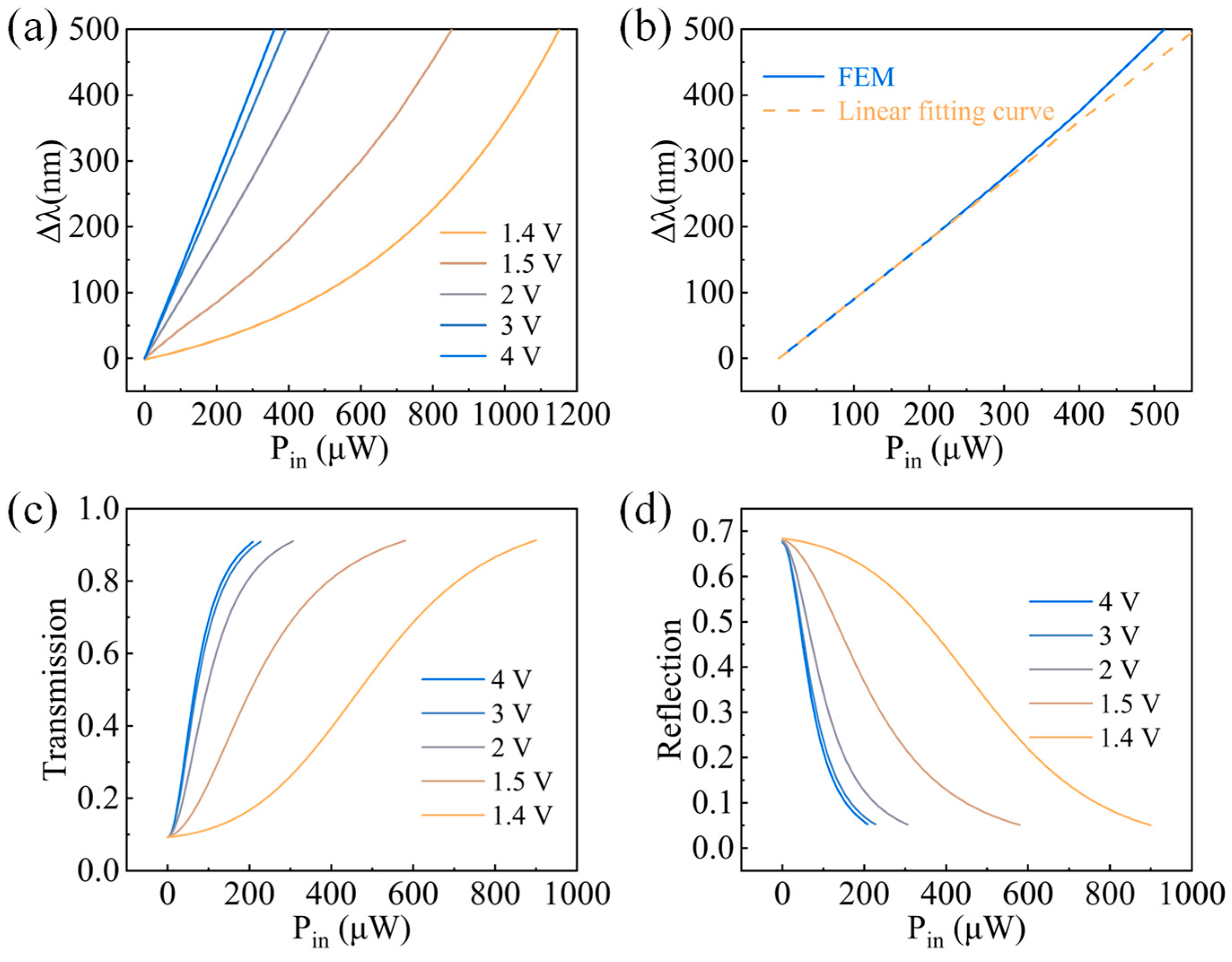
In this section, the previous finite element simulation model and the analytically predicted model are used to corroborate the improved linearity of the modulation by the ferroelectric doping principle. Figure 6a illustrates the resonance wavelength shift as a function of pump power. Applying a 2 V bias voltage significantly improves the linearity of the resonance displacement relative to the injection pump power. As shown in Figure 6b, under a 2 V bias, the response remains linear up to a pump power of 250 μW, beyond which nonlinear effects due to the TO response become significant. At lower pump powers, the TO effect, driven by ferroelectrically injected carriers, ensures a linear response. Notably, since the ferroelectric injection carriers contribute to the spectral shift, the power consumption of the device can be reduced after their injection, and tuning efficiency increased from 0.2 pm/μW to 1.36 pm/μW. Figure 6c,d depict the variations in transmittance and reflectance, respectively, at different bias voltages. Increased carrier concentration with applied voltage enhances light absorption, resulting in reduced oscillations in both transmittance and reflectance as the voltage rises.
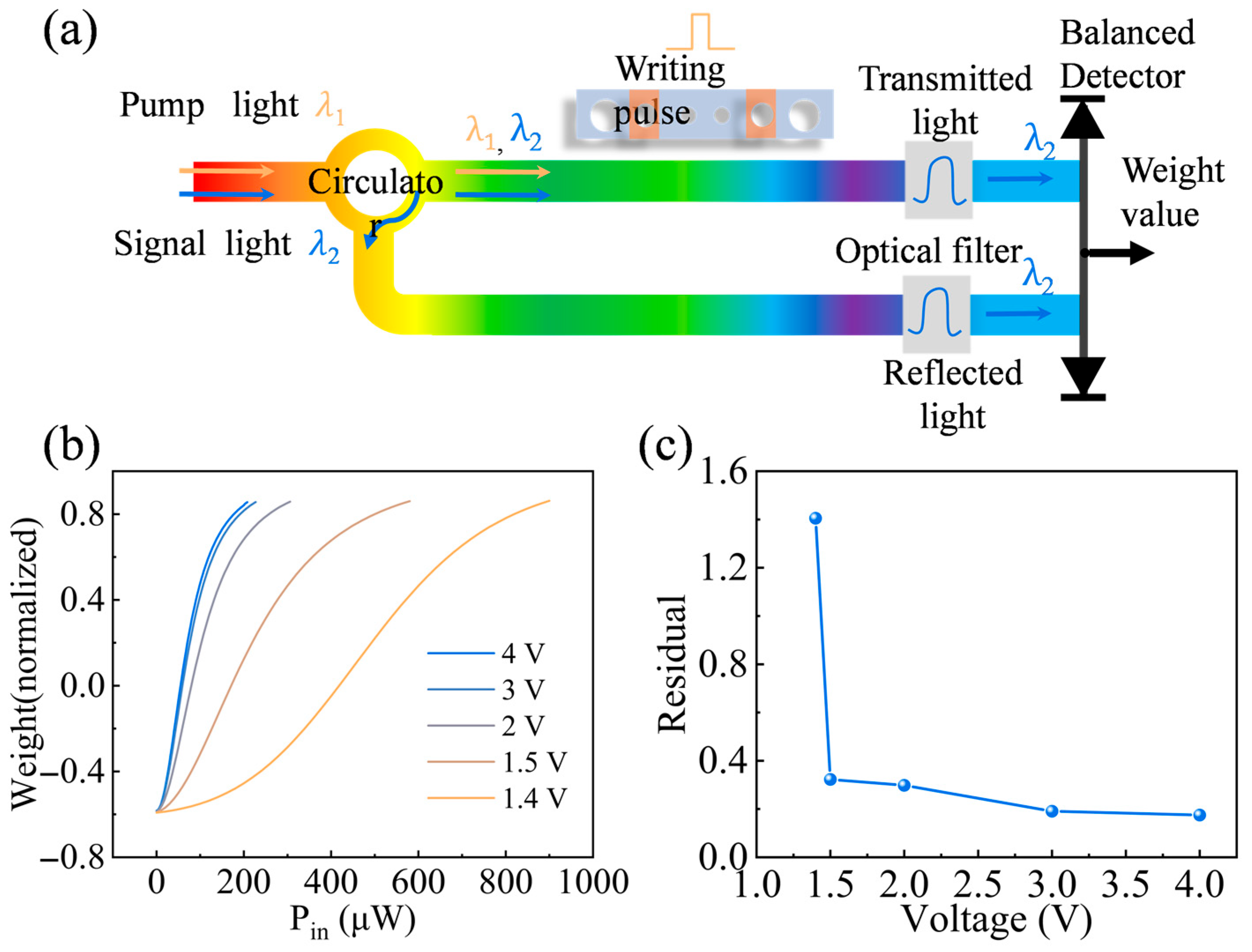
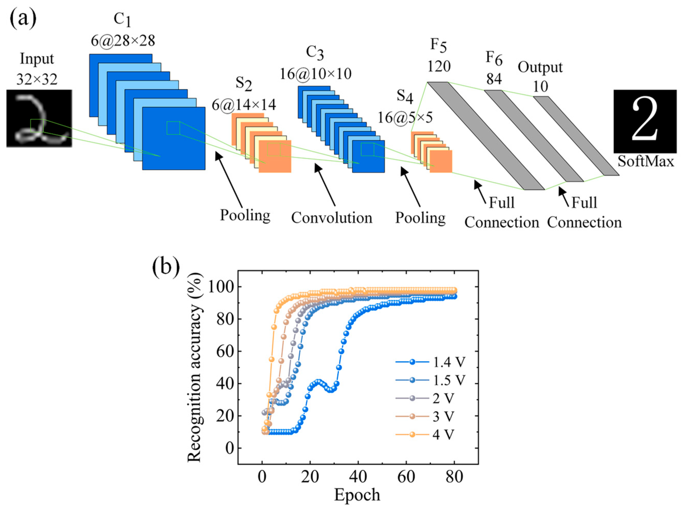
The filtering properties of the PCNBC enable weighted intensity of the input signal. As shown in Figure 7a, signals from the Through and Drop waveguides are filtered and directed to a balance detector for differential detection, allowing positive and negative weighting to distinguish excitatory and inhibitory stimulus responses. Figure 7b,c present the output of the photonic weight library architecture at various biases, along with the residuals and variations in the weights, respectively. The residual decreases from 1.4 to 0.17 with increasing voltage, indicating improved device linearity. To evaluate the performance of the all-optical synaptic device, we integrated it into Lenet5, a seven-layer convolutional neural network comprising two convolutional layers, two pooling layers, two fully connected layers, and one SoftMax layer, as illustrated in Figure 8a. Figure 8b shows the learning accuracy over 80 epochs, demonstrating that the learning speed and accuracy can be modulated by adjusting the bias voltage. The training accuracy exceeds 90% in all cases, improving from 94% to 99% with increasing voltage, underscoring the potential of our designed devices for efficient neural network training. Table 2 presents a comparison of our work with the most recent studies. Compared with other devices, our device demonstrates a certain advantage in recognition accuracy, and can be further enhanced by increasing the bias voltage. Notably, owing to the compact footprint of the PCNBC, our device achieves a significant reduction in dimension relative to other reported devices, highlighting its potential for high-density integration. These calculation results are based merely on simulations rather than experimental measurements, potential impacts arising from environmental conditions and manufacturing tolerances were not taken into account, thus these results are indicative rather than definitive.

4. Conclusions

In conclusion, we propose a dynamic all-optical synapse utilizing a HZO ferroelectric film combined with an ITO layer for nonvolatile modulation. Finite element simulations and analytical models confirm that electrostatic doping via ferroelectric materials significantly enhances device linearity. By employing the PCNBC architecture our synapse achieves an estimated footprint of 7 µm2, representing a substantial improvement over previously reported works and highlighting its potential for high-density integration. In addition, through validation with the LeNet-5 network, the device enables the realization of dynamic synaptic behavior, yielding a training accuracy exceeding 94%, which is superior to most related studies. Moreover, by tuning the bias voltage, the network achieves a training accuracy of up to 99%, improving the learning speeds. This work advances photonic neuromorphic computing by demonstrating a scalable approach to efficient, dynamic synaptic devices through the synergy of nonlinear and ferroelectric electrostatic doping effects. The improvements in linearity, reduced power consumption, and compatibility with neural network architectures position this technology as a promising candidate for next-generation neuromorphic systems.

Author Contributions

Conceptualization, D.Y.; methodology, D.Y., D.L. and H.X.; validation and formal analysis, D.L., E.Z. and J.S.; investigation, Y.W., Y.Z. and X.R.; writing—original draft preparation D.L. and H.X.; writing—review and editing, D.Y.; supervision, X.L., X.M. and Y.H.; funding acquisition, D.Y. and D.F. All authors have read and agreed to the published version of the manuscript.

Funding

This work was supported by the Natural Science Basic Research Program of Shaanxi (Program No. 2025JC-YBMS-666), CIE-Smartchip research fund No. 2024-11, and the Fundamental Research Funds for the Central Universities Grant No. YJSJ25013.

Data Availability Statement

The original contributions presented in this study are included in the article. Further inquiries can be directed to the corresponding author.

Conflicts of Interest

Author Dongming Fang was employed by the Beijing Smartchip Microelectronics Technology Company Limited. The remaining authors declare that the research was conducted in the absence of any commercial or financial relationships that could be construed as a potential conflict of interest.

References

  1. Kim, S.Y.; Yu, J.M.; Lee, G.S.; Yun, D.H.; Kim, M.S.; Kim, J.K.; Kim, D.J.; Lee, G.B.; Kim, M.S.; Han, J.K.; et al. Synaptic Segmented Transistor with Improved Linearity by Schottky Junctions and Accelerated Speed by Double-Layered Nitride. ACS Appl. Mater. Interfaces 2022, 14, 32261–32269. [Google Scholar] [CrossRef]
  2. Lisman, J. A mechanism for the Hebb and the anti-Hebb processes underlying learning and memory. Proc. Natl. Acad. Sci. USA 1989, 86, 9574–9578. [Google Scholar] [CrossRef] [PubMed]
  3. Churchland, M.M.; Cunningham, J.P.; Kaufman, M.T.; Foster, J.D.; Nuyujukian, P.; Ryu, S.I.; Shenoy, K.V. Neural population dynamics during reaching. Nature 2012, 487, 51–56. [Google Scholar] [CrossRef] [PubMed]
  4. Wen, Z.; Nguyen, H.N.; Guo, Z.; Lalli, M.A.; Wang, X.; Su, Y.; Kim, N.S.; Yoon, K.J.; Shin, J.; Zhang, C.; et al. Synaptic dysregulation in a human iPS cell model of mental disorders. Nature 2014, 515, 414–418. [Google Scholar] [CrossRef] [PubMed]
  5. Zhou, T.; Lin, X.; Wu, J.; Chen, Y.; Xie, H.; Li, Y.; Fan, J.; Wu, H.; Fang, L.; Dai, Q. Large-scale neuromorphic optoelectronic computing with a reconfigurable diffractive processing unit. Nat. Photonics 2021, 15, 367–373. [Google Scholar] [CrossRef]
  6. Prucnal, P.R.; Shastri, B.J. Neuromorphic Photonics, 1st ed.; CRC Press: Boca Raton, FL, USA, 2017. [Google Scholar]
  7. Zhang, J.; Dai, S.; Zhao, Y.; Zhang, J.; Huang, J. Recent progress in photonic synapses for neuromorphic systems. Adv. Intell. Syst. 2020, 2, 1900136. [Google Scholar] [CrossRef]
  8. Jha, A.; Huang, C.; Delima, T.F.; Peng, H.-T.; Shastri, B.; Prucnal, P.R. Nanophotonic cavity based synapse for scalable photonic neural networks. IEEE J. Sel. Top. Quantum Electron. 2022, 28, 6100908. [Google Scholar] [CrossRef]
  9. Zhang, Y.; Zeng, C.; Li, D.; Gao, G.; Huang, Z.; Yu, J.; Xia, J. High-quality-factor photonic crystal ring resonator. Opt. Lett. 2014, 39, 1282–1285. [Google Scholar] [CrossRef]
  10. Kim, M.K.; Kim, J.Y.; Kang, J.H.; Ahn, B.H.; Lee, Y.H. On-demand photonic crystal resonators. Laser Photonics Rev. 2011, 5, 479–495. [Google Scholar] [CrossRef]
  11. Maleki, M.J.; Soroosh, M.; Akbarizadeh, G.; Parandin, F.; Haddadan, F. Photonic crystal resonators in designing optical decoders. J. Optoelectron. Nanostructures 2023, 8, 1–24. [Google Scholar]
  12. Qiang, Z.; Soref, R.A.; Zhou, W. Photonic crystal ring resonators: Characteristics and applications. J. Nanosci. Nanotechnol. 2010, 10, 1495–1507. [Google Scholar] [CrossRef]
  13. Deotare, P.B.; McCutcheon, M.W.; Frank, I.W.; Khan, M.; Lončar, M. High quality factor photonic crystal nanobeam cavities. Appl. Phys. Lett. 2009, 94, 121106. [Google Scholar] [CrossRef]
  14. Quan, Q.; Deotare, P.B.; Loncar, M. Photonic crystal nanobeam cavity strongly coupled to the feeding waveguide. Appl. Phys. Lett. 2010, 96, 203102. [Google Scholar] [CrossRef]
  15. Shakoor, A.; Nozaki, K.; Kuramochi, E.; Nishiguchi, K.; Shinya, A.; Notomi, M. Compact 1D-silicon photonic crystal electro-optic modulator operating with ultra-low switching voltage and energy. Opt. Express 2014, 22, 28623–28634. [Google Scholar] [CrossRef]
  16. Zhou, H.; Qiu, C.; Jiang, X.; Zhu, Q.; He, Y.; Zhang, Y.; Su, Y.; Soref, R. Compact, submilliwatt, 2× 2 silicon thermo-optic switch based on photonic crystal nanobeam cavities. Photonics Res. 2017, 5, 108–112. [Google Scholar] [CrossRef]
  17. Nahmias, M.A.; De Lima, T.F.; Tait, A.N.; Peng, H.-T.; Shastri, B.J.; Prucnal, P.R. Photonic multiply-accumulate operations for neural networks. IEEE J. Sel. Top. Quant. Electron. 2019, 26, 7701518. [Google Scholar] [CrossRef]
  18. Uesugi, T.; Song, B.-S.; Asano, T.; Noda, S. Investigation of optical nonlinearities in an ultra-high-Q Si nanocavity in a two-dimensional photonic crystal slab. Opt. Express 2006, 14, 377–386. [Google Scholar] [CrossRef]
  19. Yao, D.; Jiang, Z.; Zhang, Y.; Xie, H.; Wang, T.; Wang, J.; Gan, X.; Han, G.; Liu, Y.; Hao, Y. Ultrahigh thermal-efficient all-optical silicon photonic crystal nanobeam cavity modulator with TPA-induced thermo-optic effect. Opt. Lett. 2023, 48, 2325–2328. [Google Scholar] [CrossRef]
  20. Chanthbouala, A.; Garcia, V.; Cherifi, R.O.; Bouzehouane, K.; Fusil, S.; Moya, X.; Xavier, S.; Yamada, H.; Deranlot, C.; Mathur, N.D. A ferroelectric memristor. Nat. Mater. 2012, 11, 860–864. [Google Scholar] [CrossRef]
  21. Tian, B.-B.; Zhong, N.; Duan, C.-G. Recent advances, perspectives, and challenges in ferroelectric synapses. Chin. Phys. B. 2020, 29, 097701. [Google Scholar] [CrossRef]
  22. Yao, D.; Li, L.; Zhang, Y.; Peng, Y.; Zhou, J.; Han, G.; Liu, Y.; Hao, Y. Energy-efficient non-volatile ferroelectric based electrostatic doping multilevel optical readout memory. Opt. Express 2022, 30, 13572–13582. [Google Scholar] [CrossRef] [PubMed]
  23. Zhang, Y.; McCutcheon, M.W.; Burgess, I.B.; Loncar, M. Ultra-high-Q TE/TM dual-polarized photonic crystal nanocavities. Opt. Lett. 2009, 34, 2694–2696. [Google Scholar] [CrossRef]
  24. Ancona, M. Density-gradient theory: A macroscopic approach to quantum confinement and tunneling in semiconductor devices. J. Comput. Electron. 2011, 10, 65–97. [Google Scholar] [CrossRef]
  25. Smith, R.C.; Ounaies, Z. A domain wall model for hysteresis in piezoelectric materials. J. Intell. Mater. Syst. Struct. 2000, 11, 62–79. [Google Scholar] [CrossRef]
  26. Kim, S.J.; Mohan, J.; Summerfelt, S.R.; Kim, J. Ferroelectric Hf0.5Zr0.5O2 thin films: A review of recent advances. JOM 2019, 71, 246–255. [Google Scholar] [CrossRef]
  27. Barclay, P.E.; Srinivasan, K.; Painter, O. Nonlinear response of silicon photonic crystal microresonators excited via an integrated waveguide and fiber taper. Opt. Express 2005, 13, 801–820. [Google Scholar] [CrossRef]
  28. Reggiani, S.; Valdinoci, M.; Colalongo, L.; Rudan, M.; Baccarani, G.; Stricker, A.D.; Illien, F.; Felber, N.; Fichtner, W.; Zullino, L. Electron and hole mobility in silicon at large operating temperatures. I. Bulk mobility. IEEE Trans. Electron. Devices 2002, 49, 490–499. [Google Scholar] [CrossRef]
  29. Hook, J.R.; Hall, H.E. Solid State Physics, 2nd ed.; John Wiley & Sons: Hoboken, NJ, USA, 2013. [Google Scholar]
  30. Zhang, Y.; Li, L.; Xie, H.; Jiang, Z.; Li, Y.; Wang, T.; Yao, D.; Liu, Y.; Han, G.; Hao, Y. Compact non-volatile ferroelectric electrostatic doping optical memory based on the epsilon-near-zero effect. Appl. Opt. 2023, 62, 950–955. [Google Scholar] [CrossRef] [PubMed]
  31. Dinu, M.; Quochi, F.; Garcia, H. Third-order nonlinearities in silicon at telecom wavelengths. Appl. Phys. Lett. 2003, 82, 2954–2956. [Google Scholar] [CrossRef]
  32. Yang, R.; Wang, Y.; Li, S.; Hu, D.; Chen, Q.; Zhuge, F.; Ye, Z.; Pi, X.; Lu, J. All-optically controlled artificial synapse based on full oxides for low-power visible neural network computing. Adv. Funct. Mater. 2024, 34, 2312444. [Google Scholar] [CrossRef]
  33. Li, Y.T.; Li, J.Z.; Ren, L.; Xu, K.; Chen, S.; Han, L.; Liu, H.; Guo, X.L.; Yu, D.L.; Li, D.H.; et al. Light-controlled reconfigurable optical synapse based on carbon nanotubes/2D perovskite heterostructure for image recognition. ACS Appl. Mater. Interfaces 2022, 14, 28221–28229. [Google Scholar] [CrossRef] [PubMed]
  34. Chen, K.; Hu, H.; Song, I.; Gobeze, H.B.; Lee, W.J.; Abtahi, A.; Schanze, K.S.; Mei, J. Organic optoelectronic synapse based on photon-modulated electrochemical doping. Nat. Photonics 2023, 17, 629–637. [Google Scholar] [CrossRef]
  35. Shrivastava, S.; Keong, L.B.; Pratik, S.; Lin, A.S.; Tseng, T.Y. Fully photon controlled synaptic memristor for neuro-inspired computing. Adv. Electron. Mater. 2023, 9, 2201093. [Google Scholar] [CrossRef]
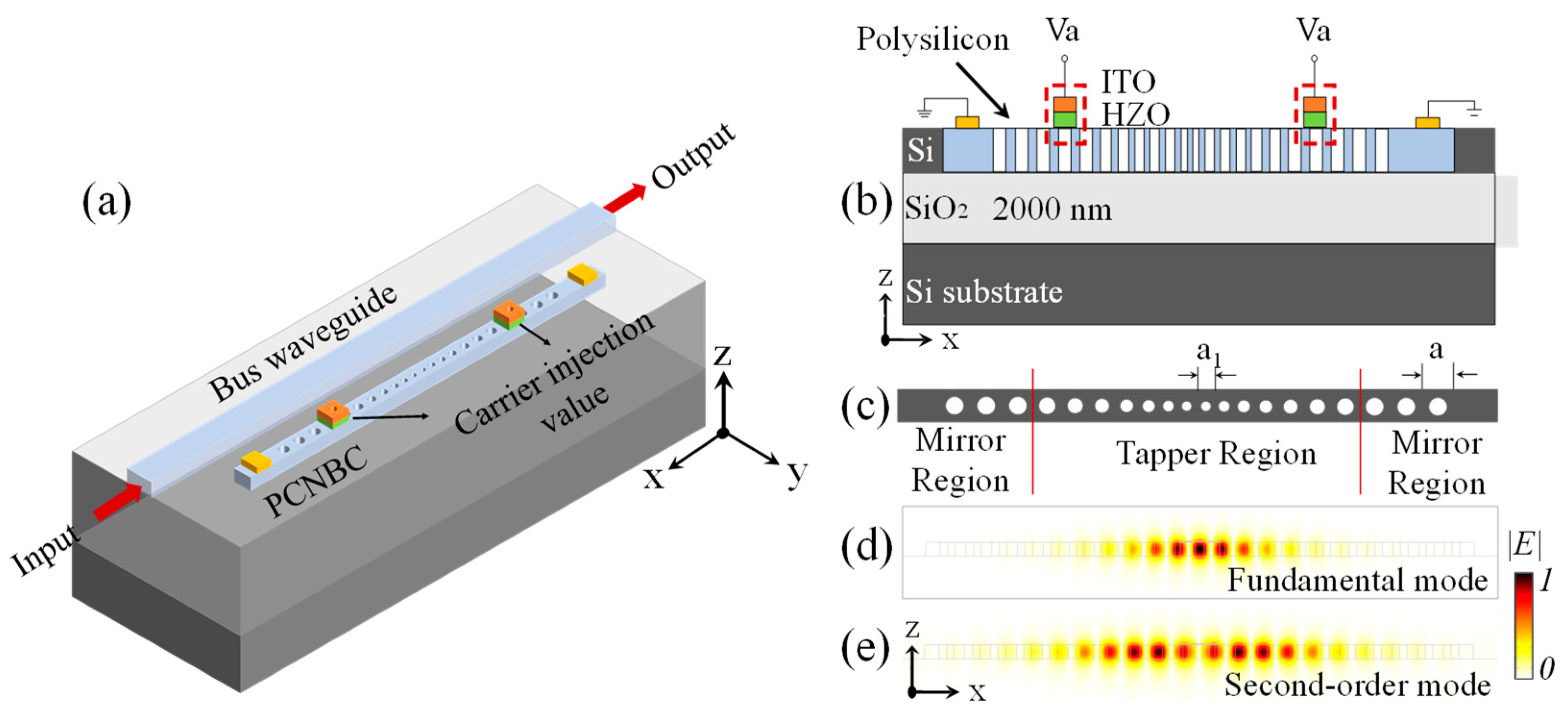
Figure 1. Schematic illustration of the proposed all-optical PCNBC synapse with ferroelectric carrier injection valve. (a) Three-dimensional view of the device. (b) Cross-sectional view of the coupled region. (c) Depiction of the 1D PCNBC design with tapered region and Bragg mirror region. Electric field distribution of fundamental mode in (d) and second-order mode in (e).
Photonics 12 00871 g001
Figure 2. (a) Non-volatile multilevel writing of the carrier injection valve. (b) Ferroelectric hysteresis loop. (c) Electric field components |Ey| and injected carrier concentration along the dotted line. (d) Principle of the optical weight tuning.
Photonics 12 00871 g002
Figure 3. Workflow of the FEM simulation process.
Photonics 12 00871 g003
Figure 4. (a) The resonance wavelength shift and the temperature increase in the central region of the nanobeam cavity in the reset state. (b) The carrier concentration distribution of polycrystalline silicon and ITO at the HZO interface. (c) The spectral drift results of the finite element calculations at 2 V, 4 V and reset.
Photonics 12 00871 g004
Figure 5. (a) and (b) are the fitted 1st mode and 2nd mode spectra with line widths of 0.228 nm and 0.498 nm, corresponding to Q factors of 5500 and 3300, respectively. (c) is a fit of the finite element calculation results and the analytical model. (d) is the change in refractive index of nanobeam cavities upon shifting of resonance wavelengths calculated by analytical models.
Photonics 12 00871 g005
Figure 6. (a) Fitting curves of the FEM under different bias pressures. (b) The FEM result curve and the linear fitting curve under 2 V bias. The transmissivity (c) and reflectivity (d) curves are simulated by FEM under different biases.
Photonics 12 00871 g006
Figure 7. (a) PCNBC-based photonic weight library architecture. (b) Weights output by photon weight library architectures at different bias voltage. (c) Residual of weight functions for different bias voltage.
Photonics 12 00871 g007
Figure 8. (a) Convolutional neural network based on Lenet5. (b) Simulating the accuracy evolution of convolutional neural network learning based on all-optical synaptic devices under five biases.
Photonics 12 00871 g008
Table 1. Parameters used for the analytical model.
ParameterDescriptionValueSource
βTPA coefficient0.83 cm·GW−1[26]
nsiThe refractive index of silicon3.48
VTPACavity volume for TPA2.325 V0 (mode 1)FEM
VFCACavity volume for free carriers1.686 V0 ( mode 1)FEM
V0Mode volume(λ/nsi)3
τreconCarrier recombination time0.5 ns[27]
RThermal resistance3880 K·mW−1FEM
μeElectron mobility80 cm·(V·s)−1[28]
μhHole mobility40 cm/V·s[28]
me *Electron effective mass0.3 m0[29]
mh *Hole effective mass0.45 m0[29]
m0Effective mass9.109 × 10−31 kg[29]
TOCThermal optic coefficient1.85 × 10−4 K−1[30]
n2Kerr coefficient0.45 × 10−13 cm2·W[31]
τCIVEnergy decay rate corresponding to ferroelectric doping0 V = 3.85 ns
2 V = 0.95 ns
4 V = 0.27 ns
FEM
* is a specific symbol for the effective mass of electrons and holes.
Table 2. Comparison of Device Performance.
TypeDimensionModulation SchemeRecognition AccuracyReconfigurable
Heterojunction [32]≥200 µm2All-optical≥93%No
Heterostructure [33]≥10 µm2Optoelectronic≥77%Yes
Electrochemical transistors [34]≥20 µm2Optoelectronic-No
Memristor [35]-Optoelectronic≥93%No
Ferroelectric injection valve [This work]7 µm2All-optical≥94%Yes
Disclaimer/Publisher’s Note: The statements, opinions and data contained in all publications are solely those of the individual author(s) and contributor(s) and not of MDPI and/or the editor(s). MDPI and/or the editor(s) disclaim responsibility for any injury to people or property resulting from any ideas, methods, instructions or products referred to in the content.