Article

Accurate, Extended-Range Indoor Visible Light Positioning via High-Efficiency MPPM Modulation with Smartphone Multi-Sensor Fusion

by
Dinh Quan Nguyen
1,2 and
Hoang Nam Nguyen
2,*
1
Department of Automation, School of Electrical and Electronic Engineering, Hanoi University of Science and Technology (HUST), Hanoi 100000, Vietnam
2
Industry 4.0 Convergence Bionics Engineering, Department of Biomedical Engineering, Pukyong National University, Busan 48513, Republic of Korea
*
Author to whom correspondence should be addressed.
Photonics 2025, 12(9), 859; https://doi.org/10.3390/photonics12090859
Submission received: 5 May 2025 / Revised: 26 May 2025 / Accepted: 30 May 2025 / Published: 27 August 2025

Abstract

Visible Light Positioning (VLP), leveraging Light-Emitting Diodes (LEDs) and smartphone CMOS cameras, provides a high-precision solution for indoor localization. However, existing systems face challenges in accuracy, latency, and robustness due to line-of-sight (LOS) limitations and inefficient signal encoding. To overcome these constraints, this paper introduces a real-time VLP framework that integrates Multi-Pulse Position Modulation (MPPM) with smartphone multi-sensor fusion. By employing MPPM, a high-efficiency encoding scheme, the proposed system transmits LED identifiers (LED-IDs) with reduced inter-symbol interference, enabling robust signal detection even under dynamic lighting conditions and at extended distances. The smartphone’s camera is a receiver that decodes the MPPM-encoded LED-ID, while accelerometer and magnetometer data compensate for device orientation and motion-induced errors. Experimental results demonstrate that the MPPM-driven approach achieves a decoding success rate of over 97% at distances up to 2.4 m, while maintaining a frame processing rate of 30 FPS and sub-35 ms latency. Furthermore, the method reduces angular errors through sensor fusion, yielding 2D positioning accuracy below 10 cm and vertical errors under 16 cm across diverse smartphone orientations. The synergy of MPPM’s spectral efficiency and multi-sensor correction establishes a new benchmark for VLP systems, enabling scalable deployment in real-world environments without requiring complex infrastructure.

Graphical Abstract

1. Introduction

Indoor positioning systems leveraging visible light communication (VLC) technology have garnered significant interest in recent years due to their potential to offer high-accuracy location-based services [1,2]. The demand for real-time indoor navigation continues to rise across various mobile applications, such as indoor service robots, hospital patient monitoring, personal shopping, and other services based on indoor location. In particular, the coronavirus disease 2019 (COVID-19) outbreak had a major global societal impact, where social distancing, surveillance, and monitoring became effective in monitoring and reducing the spread of viruses [3]. Precise tracking and positioning technologies are crucial for future pandemic responses and deploying IoT and 5G/6G networks, necessitating robust indoor–outdoor compatibility. While radio-frequency (RF) systems such as GPS and Wi-Fi struggle with accuracy indoors [4,5], VLC has emerged as a promising alternative for high-precision indoor positioning and navigation [6]. This makes VLC a key component in next-generation connectivity frameworks, particularly for applications requiring fine-grained indoor localization. VLC technology provides several advantages, including high data rates, environmental friendliness, and robust security. By leveraging the existing and ever-growing lighting infrastructure, LEDs are deployed not only for illumination but also as transmitters for data transmission, thanks to their high efficiency, energy savings, and fast response. Furthermore, VLC systems mainly utilize photodiodes (PDs) or image sensors for the receiver; these devices achieve high accuracy, up to several centimeters, making them suitable for many indoor positioning applications [7]. For PD-based positioning systems, methods such as received signal strength (RSS) and angle of arrival (AOA) are commonly employed [8,9]. In a previous study [10], the utilization of a PD as the receiver was investigated; however, integrating this into a VLC system capable of accommodating receiver tilt poses challenges. Moreover, such a system necessitates additional hardware, increasing complexity and cost. Another study [11] introduced a large-scale VLC system with a receiver orientation mechanism and accounted for tilting effects. The researchers utilized a PD receiver and employed a conventional modulation scheme in the transmitter. Additionally, a VLC positioning system considering receiver tilt angle for position estimation was discussed in [12]. However, the specific receiver device utilized remains unspecified, and the study presented simulation-based performance within a limited positioning area.
Recent studies [13,14] have delved into visible light positioning (VLP) by leveraging smartphone inertial sensors, magnetic sensors, accelerometers, and other compatible devices to improve positioning accuracy. Furthermore, inquiries have been made into three-dimensional indoor positioning systems based on VLC, which consider receiver tilt and utilize received signal strength [10]. In addition, due to advancements in smartphone technology, particularly the integration of high-resolution Complementary Metal–Oxide–Semiconductor (CMOS) sensor cameras, the adoption of VLC for indoor positioning has been facilitated. Smartphones equipped with built-in cameras provide an ideal platform to integrate VLC-guided indoor navigation with various mobile applications. The CMOS image sensors in these cameras enable smartphones to detect and decode data transmitted by VLC-enabled light sources, such as LED lamps, in a manner that is imperceptible to human vision [15]. This integration enhances the versatility and accessibility of indoor positioning systems, allowing users to leverage their smartphones for accurate and efficient navigation in indoor environments.
Existing VLP systems face persistent challenges in accuracy and robustness, particularly under dynamic smartphone orientations or partial occlusions. To overcome these limitations, we propose a sensor fusion framework that synergizes smartphone cameras, inertial sensors, and LED-based VLC, as shown in Figure 1. Leveraging multi-pulse position modulation (MPPM) for high-speed LED-ID encoding, our system achieves real-time 3D positioning with horizontal errors below 10 cm, a significant improvement over the conventional single-sensor approach. Furthermore, by integrating accelerometer and magnetometer data, the design dynamically compensates for orientation shifts, enabling reliable performance even in non-ideal lighting conditions. Compliance with IEEE 802.15.7 standards [16] ensures compatibility with existing LED infrastructure, while experimental validation confirms scalability across large indoor environments.
The remainder of this paper is structured as follows: Section 2 reviews the literature on existing VLP systems and presents a comparative analysis between our results and previous studies. Section 3 presents a comprehensive overview of our VLP system for indoor positioning, with particular emphasis on optimal modulation technique. Section 4 elaborates on the mathematical modeling and algorithmic framework of our proposed VLP system. Section 5 details the experimental setup and presents a thorough analysis of the empirical results. Finally, Section 6 summarizes our conclusions based on the experimental findings and identifies promising directions for future research and development.

2. Related Work

In recent years, indoor positioning methods have attracted considerable attention and have become a topic of considerable interest. Several popular technologies have been proposed for indoor positioning applications, such as radio-frequency identification (RFID), ultra-wideband (UWB), Wi-Fi, and Bluetooth [17]. Many RF positioning systems rely on received signal strength (RSS) to estimate the distance between transmitter and receiver, but they are susceptible to electromagnetic interference and multipath reflections in indoor environments. In contrast, visible light positioning (VLP) typically operates with the line of sight (LOS) between the transmitter and receiver, allowing precise positioning through methods such as time of arrival (TOA), angle of arrival (AoA), or visibility analysis [18]. VLP using smartphones has been an active area of research in recent years, with several systems proposed to address indoor localization challenges. ALiSA [19], LiDR [20], Amari and Keche’s method [21], Luxapose [22], and PIXEL [23] are notable examples that leverage smartphone sensors for VLP. For instance, ALiSA [19] utilizes the ambient light sensor (ALS) in smartphones to achieve sub-meter accuracy (<0.21 m at the 90th percentile) with low power consumption, but it is limited by low sampling rates and offline processing. LiDR [20] combines VLP with Pedestrian Dead Reckoning (PDR) using smartphone cameras and inertial sensors, achieving real-time positioning with a mean error of <0.7 m over long tracks, though it relies on specific LED geometries for heading correction. Similarly, Amari and Keche [21] propose a camera-based VLP system with high accuracy (<2 cm), but it requires complex image processing and is sensitive to phone tilt angles. However, these systems often face limitations in terms of latency, accuracy, and robustness due to factors such as line-of-sight constraints and single-sensor dependency. To provide a comprehensive comparison, Table 1 summarizes the performance of these existing smartphone-based VLP systems alongside our proposed system. As shown, our approach significantly improves processing time and accuracy, achieving a latency of 30 ms and an accuracy of approximately 10 cm, outperforming previous methods. This comparison highlights the advancements of our system, upon which we will further elaborate in the subsequent sections.

3. Overview of the Proposed VLC System for Indoor Positioning

3.1. Proposed Modulation Scheme for Multi-LED ID Encoding

The design of efficient modulation schemes is critical for VLC systems, particularly in applications requiring simultaneous data transmission and illumination control. Traditional pulse-position modulation (PPM) techniques, while effective in optimizing bandwidth, often neglect the dynamic brightness requirements inherent in LED-based systems. This limitation becomes pronounced in optical camera communication (OCC), where maintaining consistent illumination levels while ensuring high-speed data transmission is essential for user comfort and system reliability [24,25,26]. Existing approaches, such as those prioritizing bandwidth efficiency [27,28], fail to address the dual challenges of adaptive brightness adjustment and robust data encoding—a gap that undermines their practicality in real-world smartphone-based positioning systems. For instance, conventional On–Off Keying (OOK), which modulates data by switching LEDs between fully ON (“1”) and OFF (“0”) states, suffers from poor bandwidth efficiency (1 bit/symbol) and frequent brightness fluctuations, rendering it unsuitable for illumination-centric VLC systems [15]. To bridge this gap, we propose a multi-pulse position modulation (MPPM) scheme tailored for VLC systems utilizing smartphone cameras as receivers. Unlike PPM and OOK, MPPM encodes information through the positions of multiple pulses within a fixed time slot, ensuring stable illumination levels by maintaining a constant number of active pulses per symbol [29].
In MPPM, multiple pulses are embedded within a fixed-duration signal block, where information is encoded through the unique spatiotemporal arrangement of active pulses. The information-carrying capacity of MPPM is governed by two key parameters: the total number of temporal positions within a signal block (n) and the number of active pulse slots (r), as illustrated in Figure 2. The maximum number of different characters (symbols) that can be encoded is calculated as C n r = n ! r ! ( n r ) ! , with r { 1 , 2 , , n 1 } . A codeword is defined as a sequence of characters (bits) used to represent a unit of information. The maximum number of information bits (codewords) transmitted per signal block is given by log 2 ( C n r ) , whereas conventional PPM transmits log 2 ( n ) bits/symbols. This results in the same bandwidth for MPPM with the same transmission performance. With r being the number of pulses in each signal block, the bandwidth is reduced to 1 r compared to PPM [30]. Beyond its spectral efficiency, MPPM also provides a flexible means of brightness control, which is particularly useful in OCC systems. For a fixed n, the perceived brightness of the transmitted signal can be adjusted by varying the value of r. Specifically, smaller values of r yield dimmer light emissions (e.g., r = 1 produces minimum brightness), whereas larger values (e.g., r = n 1 ) correspond to higher brightness levels. This tunability enables dynamic adaptation to ambient lighting conditions or energy-saving requirements without altering the overall communication structure. Table 2 summarizes various MPPM configurations with n = 8 , highlighting the trade-offs between brightness, encoding capacity, and symbol representation.
To illustrate the encoding/decoding process, a previous study constructed a matrix [30] where each row corresponds to a specific value (pvi) of the parameter r. For the r th row and i th column with r { 1 , 2 , , n 1 } and i { 1 , 2 , , n } , the corresponding value ( r , i ) is obtained as (1):
( r , i ) = C n 1 r 1 r ( n i ) 0 r > ( n i )
Algorithm 1 presents the pseudo-code for the data encoding process. The proposed encoding algorithm performs a unique mapping of a given luminosity index from its decimal representation to a binary sequence of length n, where r represents the number of bits set to 1 within the sequence.
Algorithm 1 Encoding elgorithm
1:
Input: Variables n , r , s y
2:
Output: Encoded Codeword c w
3:
while  n > 0   do
4:
    if  0 < r < n  then
5:
         y = C n 1 r
6:
    else
7:
         y = 0
8:
    end if
9:
    if  y s y  and  r > 0  then
10:
         s k = s k + 1
11:
         c w [ n ] = 1
12:
         r = r 1
13:
    else
14:
         c w [ n ] = 0
15:
    end if
16:
     n = n 1
17:
end while
The decoding algorithm, as outlined in Algorithm 2, processes the codeword sequentially from the most significant bit (MSB) to the least significant bit (LSB), based on the bit position in the codeword with a value of 1 and parameter r. The codeword is analyzed in reverse order to ensure error detection, beginning at the last position ( n 1 ) and progressing to the first position ( 0 ) . This approach effectively identifies all bit errors except in cases where the number of errors is even, with half resulting from bits with a value of 1 being incorrectly decoded as 0 and the other half from bits with a value of 0 being decoded as 1. Additionally, the symbol boundaries remain unaffected in the presence of bit errors, as the number of decoded bits consistently equals the number of transmitted bits.
Algorithm 2 Decoding algorithm
1:
Input: Codeword c w of length n
2:
Output: Data symbol s k , r
3:
for  i n to 1 do
4:
    if  c w [ i ] = = 1  then
5:
        if  i > r  then
6:
            s k s k + C r i 1
7:
            r r 1
8:
        end if
9:
    end if
10:
end for

3.2. Parameter Optimization Analysis

3.2.1. Frame Rate and Frequency Flicker

In OCC systems, an LED flickering at frequency f LED generates alternating light/dark stripes in the captured sensor image as shown in Figure 3. The stripe width (in pixels) is determined by (2):
S = 1 f LED × t rowReadout
where t rowReadout is the time to read each pixel row (vertically) of an image. The practical frame rate is reduced by the inter-frame gap (IFG) [31], as defined in Equation (3). To mitigate data loss caused by IFG, error correction codes or repeated transmissions are required, rather than guard intervals or adaptive modulation.
Frame rate = 1 t f = 1 n × t rowReadout + t IFG
where n is the width of the image (pixels), t frameReadout = n × t rowReadout is the total time to read each pixel row, and t f is the time including both t frameReadout and synthesizing time.

3.2.2. Transmission Distance and Dimension of LED

In the VLP system, both the distance from the LED to the smartphone and the size of the are factors that directly influence the width of the bright/dark stripes and overall transceiver performance. As the captured LED image size increases, the width of the bright/dark stripes also increases, which reduces errors in position determination within the data decoding algorithm. Additionally, maintaining reliable performance is possible even at higher transmission frequencies. The relationship between the size of the captured LED image and the real LED size is determined by the camera’s field of view, as in (4):
d = D × f H
where d is the dimension of an LED in the image, D is the diameter of a real LED, H is the distance between the LED and the smartphone, and f is the focal length. In Formula (3), assume t f = h × t rowReadout , with t IFG having a negligible impact (h is the vertical pixel count (height) of the image), and assume the data frame containing k bits ( S Data ); the size of the LED in pixels ( S LED ) will be given by (5) and (6):
S Data = k × h f LED × t f
S LED = h S Sensor × d = h × D S Sensor × H × f
where S Sensor is the vertical dimension according to the sensor size. From (5) and (6), the maximum number of transmitted bits per LED is given by (7):
k 1 H × D × f S Sensor × f LED × t f

4. Proposed Visible Light Positioning System Architecture

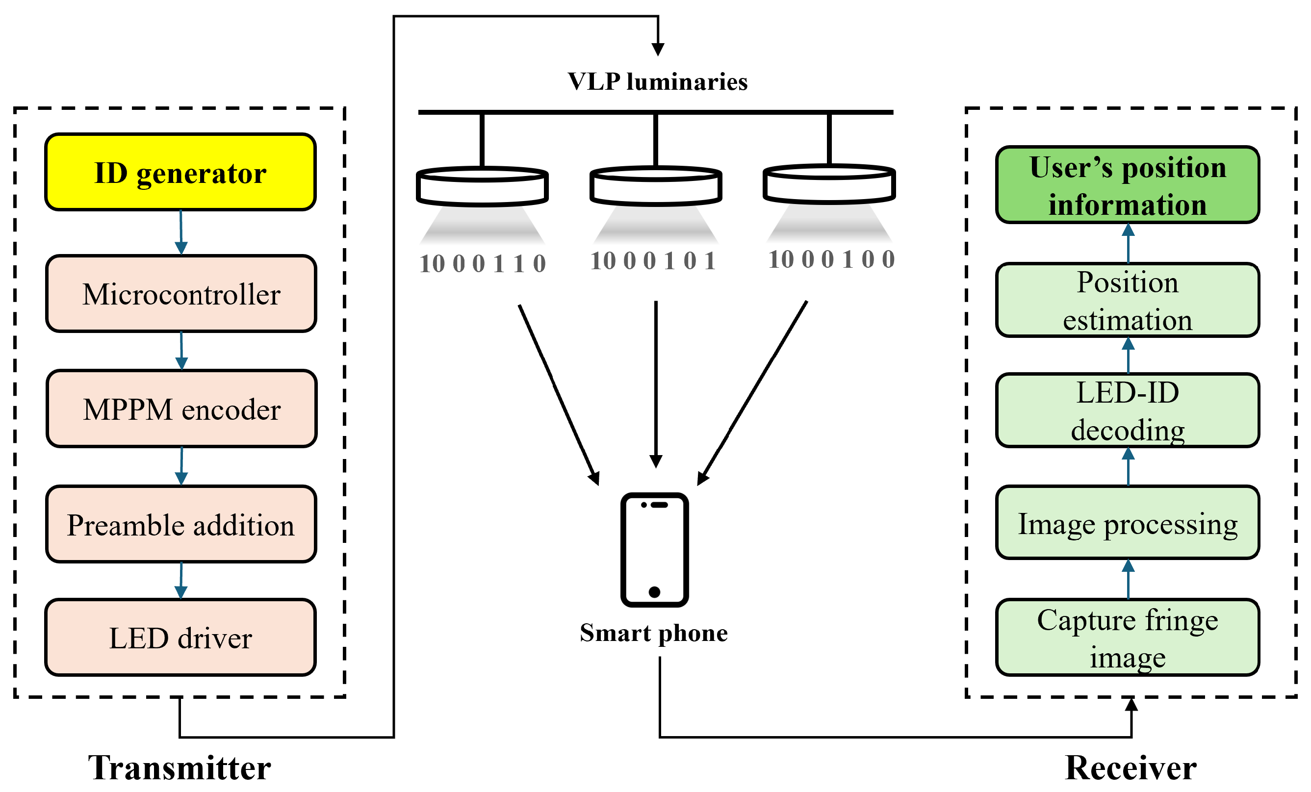
The proposed system primarily consists of two hardware components: LED luminaires and an off-the-shelf smartphone, as illustrated in Figure 4. Each luminaire is assigned to a unique identifier (ID), which is generated through the modulation process. Meanwhile, the smartphone performs a dual function: it decodes the data containing the LED-ID and estimates its position relative to each individual LED luminaire.

4.1. Transmitter Section

4.1.1. Transmitter Design

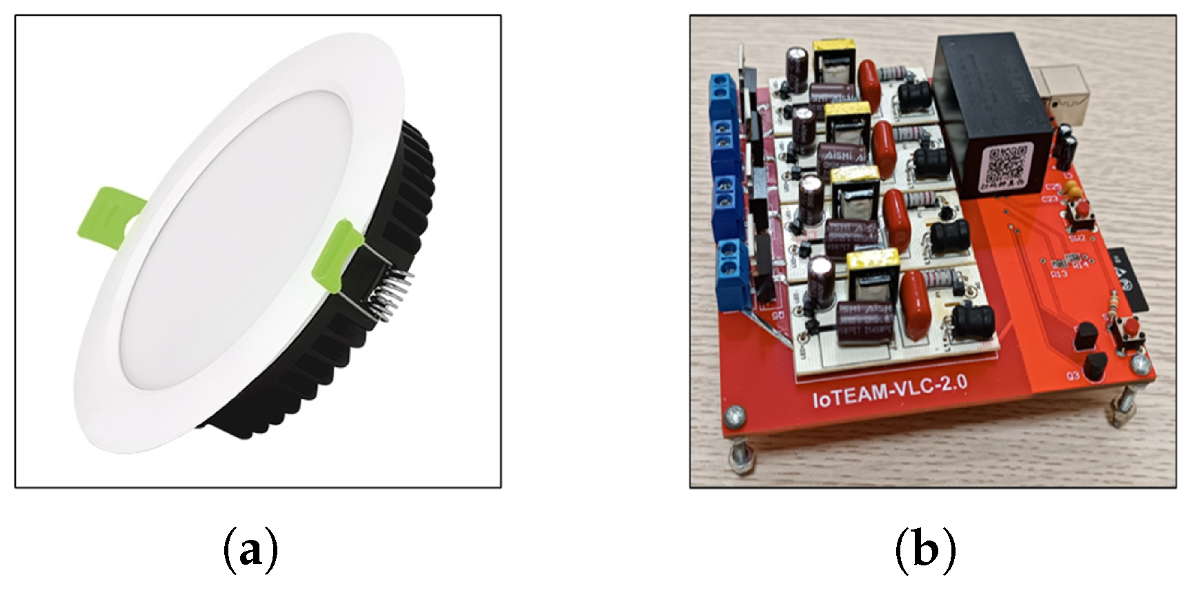
We design a transmitter system using hardware that includes commercial LED ceiling lights and an ESP32–WROVER microcontroller as shown in Figure 5 and  Figure 6. Each LED illuminator is embedded with an 8/16/32-bit microcontroller (MCU) that encodes the unique ID into a codeword suitable for not only optical transmission but also flicker reduction. The LED controller is responsible for converting this codeword into a modulated digital signal and controlling the LED illuminator to transmit the signal.

4.1.2. Transmitter LED Modulation

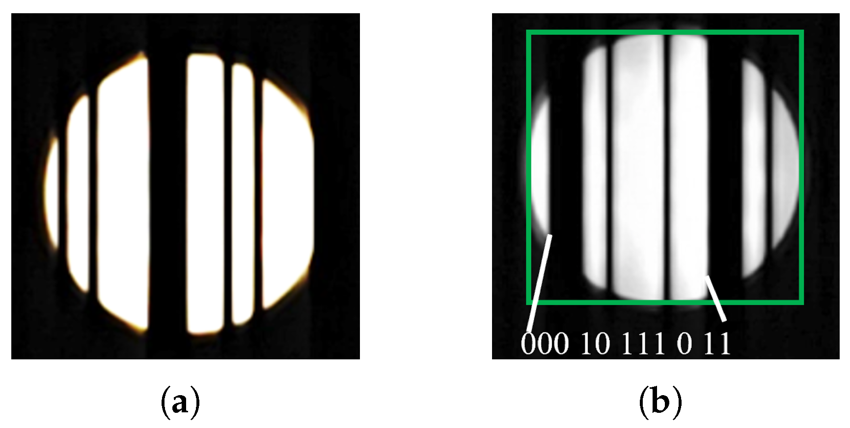
Based on the advantages of the proposed MPPM scheme, we propose using this technique to enhance transmission efficiency, particularly by increasing data decoding speed and transmission distance in practical applications. This method of signal generation leverages the rolling shutter mechanism of the CMOS image sensor. The encoding algorithm specifies the content and the number of signal bits in each data frame corresponding to each packet. The structure of a data frame includes a preamble (5 bits) and payload (n bits) as illustrated in Figure 7, and the results of encoding are shown in Table 3. Notably, the core principle of these data frames is that they are transmitted and repeated sufficiently to avoid data loss, as shown in Figure 8a.
The experimental configuration comprises an indoor LED system mounted at a height of 3   m , with the smartphone-to-LED distance constrained within 1   m H 2.4   m . To ensure the acquisition of a complete k-bit data frame as shown in Figure 8b and minimize decoding errors, the transmission frame should adhere to the condition S data s LED 3 while maintaining continuous repetition. The transmitter employs LED bulbs of diameter D = 0.1   m , and the receiver utilizes the front camera of a Vsmart Aris smartphone characterized by an exposure time t f = 1 30   s , a focal length f = 2.82   mm , a pixel size of 0.001   mm , and an image resolution of 3840 × 2160   pixels . As derived from Formula (7), the maximum permissible bit count per frame is 11 bits. The frame structure incorporates a 5-bit preamble code [ 1 , 0 , 0 , 0 , 1 ] followed by a 6-bit data segment encoded via a modified MPPM scheme, denoted as MPPM (6,4). To preclude ambiguity between the preamble’s dark stripes and those of the data segment, the post-modulation data segment is restricted to a maximum of two “0” bits, thereby limiting the number of “1” bits to r 4 . The theoretical data capacity, calculated as log 2 C n r (where r = 4 ), yields approximately 3.9   bits . However, the aggregate frame length—comprising both preamble and data—remains 11   bits , with the preamble’s two prominent dark stripes demarcating the frame boundaries

4.2. Image Processing Algorithm for LED–ID Feature Extraction

We developed a camera-based software module to continuously capture images of data-carrying light sources. Image processing is performed locally on the device, utilizing both the CPU and the GPU to enable real-time decoding of each frame and extraction of LED-ID information. This on-device processing eliminates the need for external servers, thereby reducing latency and improving system efficiency in decoding visible light communication signals. The receiver’s primary task is to decode the transmitted message frame, represented by alternating light and dark stripes captured by the CMOS image sensor. As illustrated in Figure 9, the decoding process follows a structured pipeline comprising nine sequential steps, ensuring accurate and reliable data extraction from each captured frame.
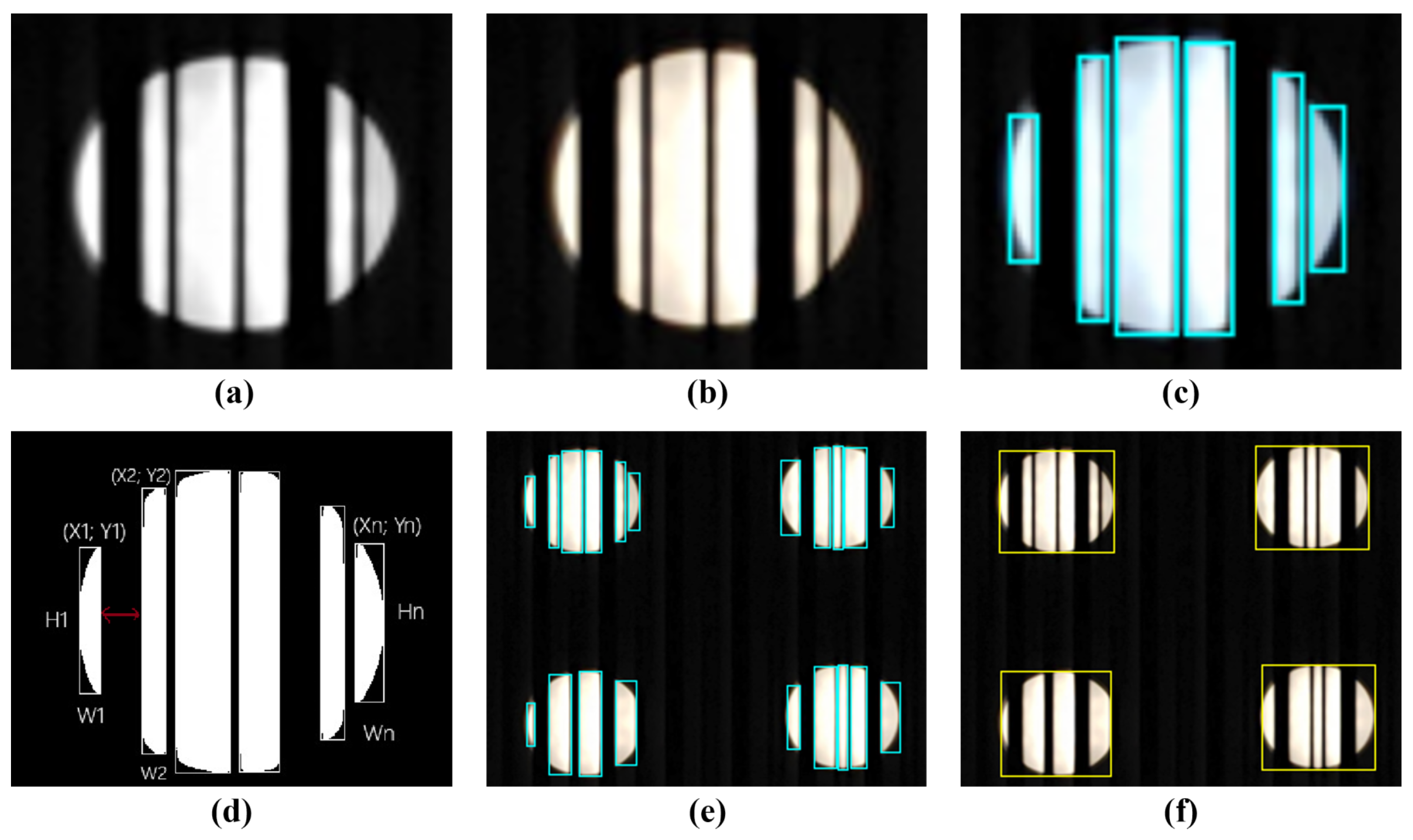
Initially, the image captured by the smartphone’s CMOS sensor as in Figure 10a is converted into grayscale as in Figure 10b and binarized using the Otsu algorithm, which determines an optimal threshold by minimizing intra-class variance. Pixels above this threshold are set to 255, and those below it are set to 0. A contour-finding method is then applied to detect white stripe objects as in Figure 10c, and their bounding boxes are extracted as in Figure 10d, providing coordinates and dimensions for LED localization.
As contour detection is stochastic, contours must be clustered into distinct LED groups. This is achieved using DBSCAN (Density-Based Spatial Clustering of Applications with Noise), which clusters contour centers within a radius ε (epsilon) as shown in Figure 10f. DBSCAN handles variations in LED projections due to viewing angles and distance. According to Formula (6), the LED lights are at least 0.1   m apart, and the distance from the LED light to the device is at most 2   m . We derive the minimum distance of the LED lights in the image as d LED = w × 0.1 × f S sensor × 2 , where w is the horizontal pixel count (width) of the image sensor. Once clusters are identified, each LED’s bright stripes are located, and dark stripe widths are calculated as: d a r k s i z e i = x i + 1 x i w i . The width between the two widest dark stripes corresponds to an 11-bit data frame (5-bit preamble and 6-bit payload). By averaging this width, the bit width is derived, enabling the reconstruction of the binary data sequence. Finally, after removing the preamble, the payload is passed to the decoding algorithm.

4.3. Position Estimation Algorithm

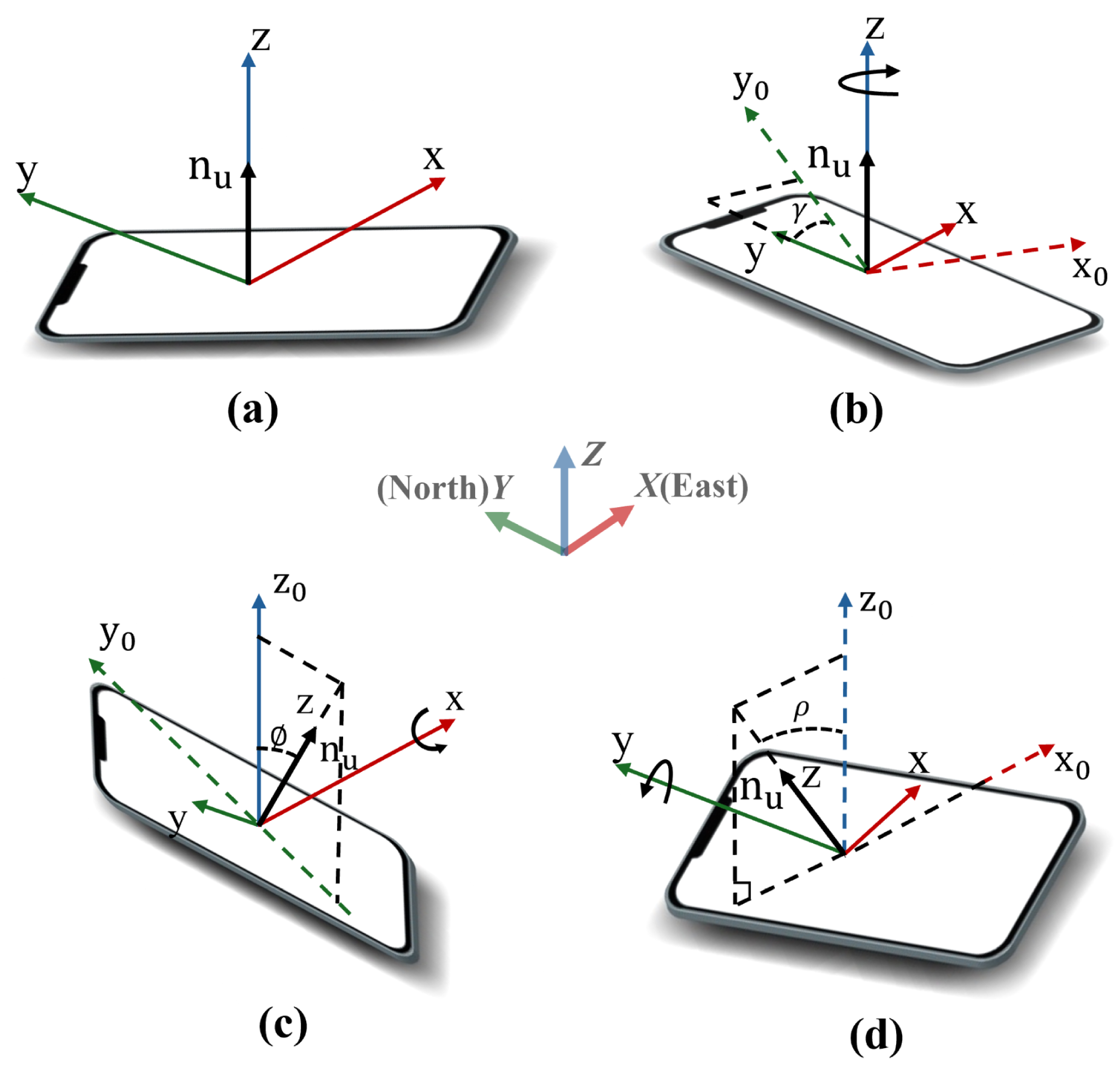
Recent VLP schemes usually require two to three LEDs [24,32] which complicates luminaire layout and increases processing time. In contrast, we combine a single LED with the smartphone’s inertial/magnetic sensors to obtain both absolute and orientation-corrected coordinates in real time. Figure 11 illustrates the device attitudes (roll, pitch, and yaw) considered.

Basic Position of the Receiver

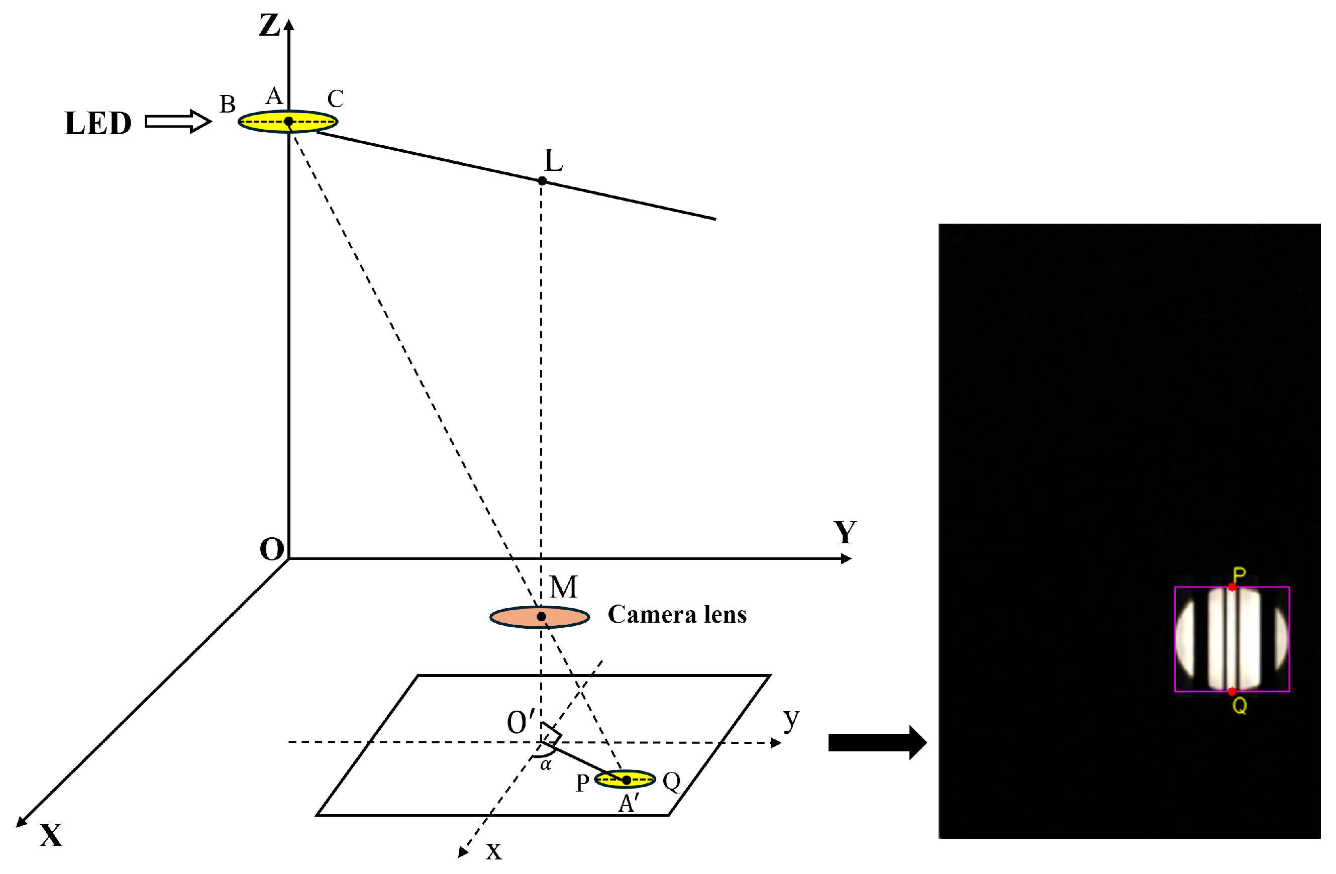
First, in this study, we define the basic position of the receiving device as the state where the phone’s plane is parallel to the lamp (or the floor plane), as shown in Figure 11a. This means that we do not consider the influence of tilt angles caused by user behavior. To estimate the phone’s position, two coordinate systems are assigned: the world coordinate system O X Y Z , whose origin O is the LED’s floor projection, and the image coordinate system O x y , centered on the smartphone screen, as shown in Figure 12. Let us assume that the receiver is at a position A ( x , y , z ) in the real coordinate system O X Y Z and that the LED projects to A ( x 0 , y 0 ) in O x y . Let P and Q denote the uppermost and lowermost LED pixels, respectively. The LED image diameter and the distance from O to the LED center are calculated in Equations (8) and (9).
d = ( x P x Q ) 2 + ( y P y Q ) 2
O A = x 0 2 + y 0 2
Applying the same ratio formula as in (4), the distance from the origin of the real coordinate system to the phone position is computed as in (10):
O A = D × O A d
where D is the LED diameter. According to the original design, the height of the lamp above the ground is a known value, denoted as L. Thus, the z coordinate of the phone along the vertical axis O Z in real space can be calculated by (11):
z = L H
By determining the center of the LED image in the image coordinate system, A ( x 0 , y 0 ) , we can express the phone’s horizontal bearing as in (12):
α = a r c t a n ( y 0 x 0 ) + 180 °
where the additional 180 ° term expands the angle from the ( 90 ° , 90 ° ) output of arctan to the full 0– 360 ° range used in the word coordinate. Finally, the phone’s x and y coordinates in the real coordinate system are calculated as in (13) to obtain the 3D position estimate ( x , y , z ).
x = O A × c o s ( α ) ; y = O A × s i n ( α )

4.4. Estimating Position with Rotation Angles

In practical scenarios, where the smartphone is subject to unintentional tilting due to human handling, the resulting distortion in the captured LED image necessitates the correction of the base case coordinates by accounting for the three intrinsic rotation angles: yaw ( γ ), pitch ( ϕ ), and roll ( ρ ), as depicted in Figure 11b–d. Specifically, the yaw angle is computed through the utilization of the mobile device’s magnetic field sensor, which measures the magnetic field intensity along the x- and y-axes, thereby enabling estimation of the device’s directional deviation relative to geomagnetic north [34]. In parallel, the pitch and roll angles are inferred from the readings of the embedded accelerometer, which senses linear acceleration along all three axes (x, y, and z); under static or uniformly linear motion conditions, such readings predominantly reflect the gravitational component, facilitating the estimation of device orientation. These angular corrections are defined with respect to two coordinate systems: the Earth-fixed world coordinate frame O X Y Z , where O X points east, O Y points north, and O Z points upward, and the device-bound body frame O x y z . According to the right-hand rule, yaw corresponds to a rotation about the O z -axis, pitch about the O x -axis, and roll about the O y -axis.
Assuming that the gravitational acceleration acting along the x, y, and z axes is denoted as A x , A y , and A z , respectively, with the unit m / s 2 , the pitch angle and roll angle of the device are computed as in (14) and (15):
ϕ = arctan A x A y 2 + A z 2
ρ = arctan A y A x 2 + A z 2
Instead of adjusting pixel coordinates separately, a single right-handed, intrinsic rotation brings the phone (body) coordinate system O x y z into the Earth-fixed coordinate system O X Y Z is calculated by (16):
R cam = R z ( γ ) R x ( ϕ ) R y ( ρ ) = cos γ sin γ 0 sin γ cos γ 0 0 0 1 × 1 0 0 0 cos ϕ sin ϕ 0 sin ϕ cos ϕ × cos ρ 0 sin ρ 0 1 0 sin ρ 0 cos ρ = C γ C ϕ C γ S ϕ S ρ S γ C ρ C γ S ϕ C ρ + S γ S ρ S γ C ϕ S γ S ϕ S ρ + C γ C ρ S γ S ϕ C ρ C γ S ρ S ϕ C ϕ S ρ C ϕ C ρ
This yaw/pitch/roll angle is supported by Android/iOS orientation APIs; hence, ϕ , ρ , and γ can be substituted directly without axis mapping. Let p = [ x , y , z ] T be the position obtained in the non-tilted case. The world coordinates are computed as in (17):
p 0 = R cam × p
The vector P 0 = ( X 0 , Y 0 , Z 0 ) therefore yields the phone’s 3D location under arbitrary orientations while still relying on a single ceiling-mounted LED.

5. Experiment and Results

5.1. Experimental Setup

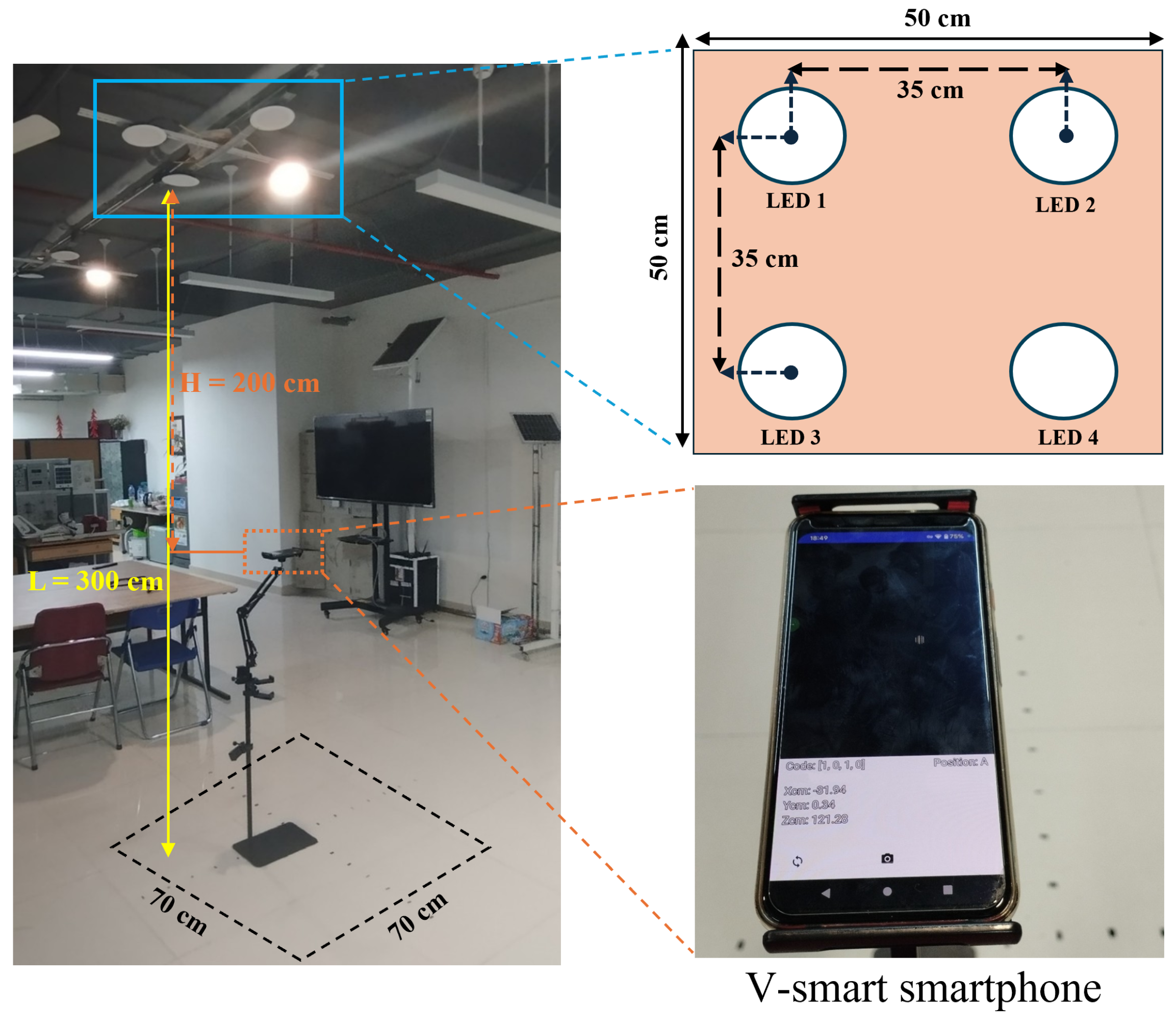
The experimental configuration was established within a controlled laboratory setting, employing a downlight LED cluster as the transmitter and a V-smart smartphone integrated with a CMOS image sensor as the receiver. As shown in Figure 13, the system was evaluated across a 70   cm × 70   cm floor area, with the transmitter array mounted at a vertical height of 300   cm . A critical objective of this study involved optimizing the inter-LED spacing within the parallel cluster configuration to maximize data transmission accuracy under ceiling heights spanning 300–400 cm. Prior investigations by Nam et al. [35] demonstrated that inter-LED distances of 35–50 cm yield peak transmission efficiency for ceiling elevations between 200   cm and 300   cm , offering foundational guidelines for designing LED clusters in indoor positioning systems. Building upon these findings, the present study implemented clusters comprising multiple LEDs arranged with uniform center-to-center spacing of 35   cm . This configuration was engineered to concurrently fulfill dual objectives: maintaining adequate illumination and enabling high-fidelity data transmission. The selected spacing aligns with empirical thresholds identified in prior work while addressing scalability for environments with elevated ceilings.

5.2. Experimental Results

5.2.1. Decoding Error Rate

In the transmission experiment, the system’s transmission–reception performance was evaluated through LED-ID data transmission, with a focus on two critical metrics: the decodable frame rate (DFR) and the bit error rate (BER). To assess robustness under varying conditions, the distance between the LED and the smartphone was systematically adjusted from 150 cm to 240 cm. As established in prior analysis, LED flicker frequency significantly influences transmission distance, efficiency, and decoding success rates. Consequently, experiments were designed to investigate the effects of varying flicker frequencies, aiming to identify the optimal frequency for reliable LED-ID transmission.
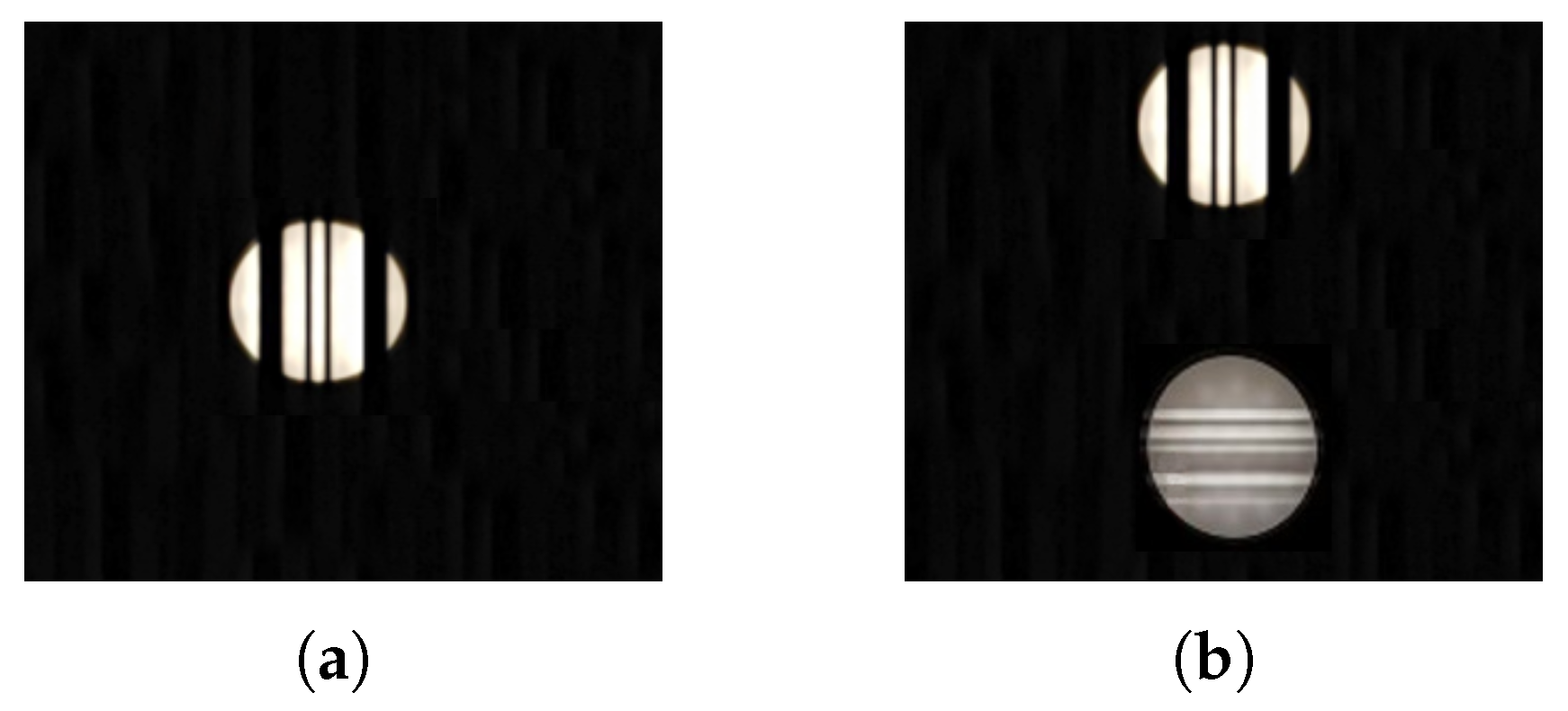
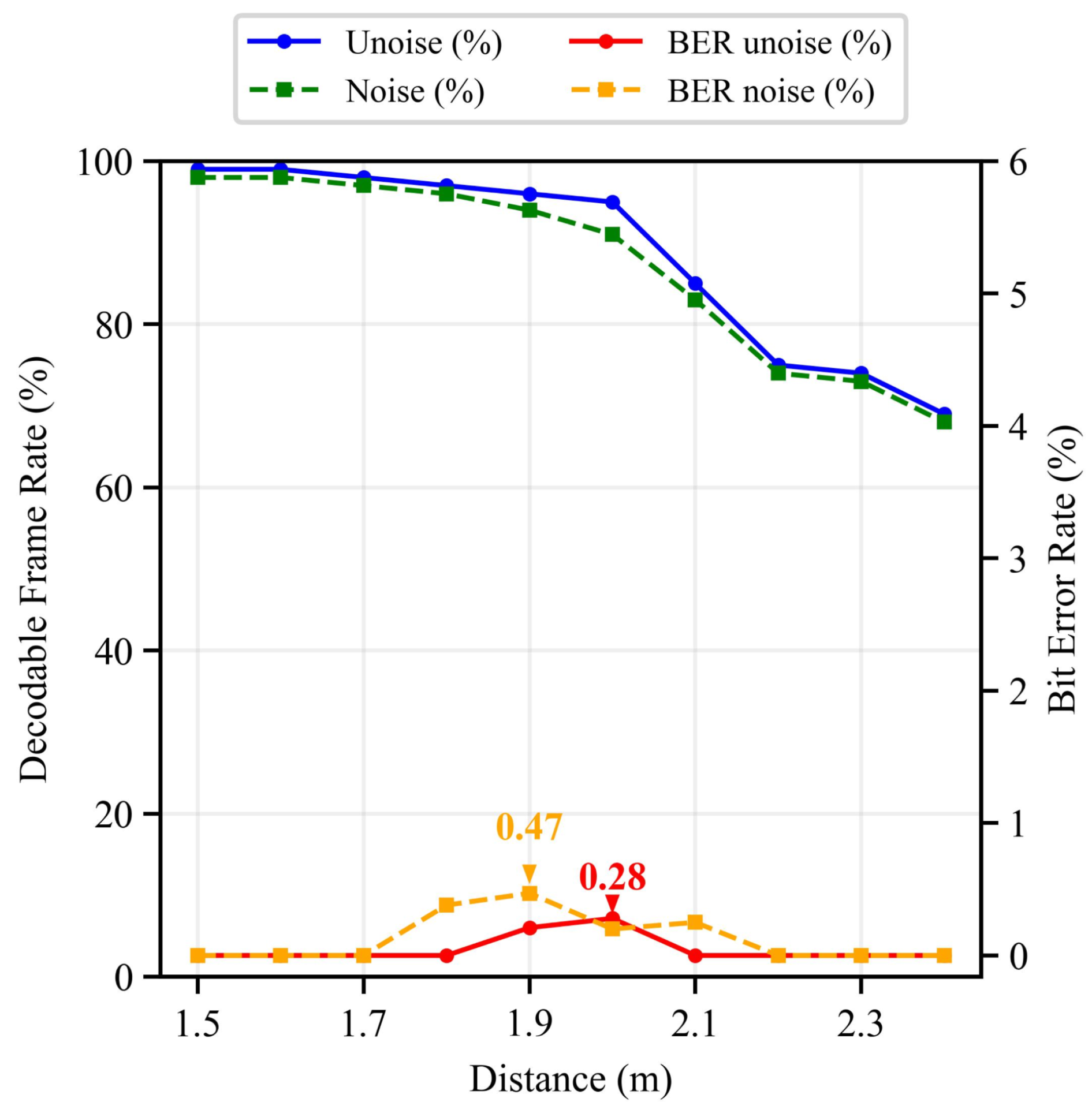
First, we conducted measurements to assess the BER and DFR under two scenarios: Scenario 1.1, where a single LED functioned as both illumination source and data transmitter, as shown in Figure 14a, and Scenario 1.2, where an additional uncoded LED was introduced as an interfering light source to simulate noise (Figure 14b). The LED transmitted a data bit sequence at 16 kHz, corresponding to the LED-ID1 code outlined in Table 2. As illustrated in Figure 15, the BER for both scenarios exhibited a linear correlation with transmission distance. Within the 1.5–2.0 m range, the DFR exceeded 90% in both cases, whereas the BER remained negligible (<1%). However, beyond 2.1 m, the DFR declined markedly to below 80%, although the BER remained at low levels. This deterioration can be attributed to the increased distance, causing the LED’s projected image to diminish in size, thereby compromising the consistent inclusion of the data frame within the captured image and impeding data readability. Notably, although ambient light interference was present, its negative impact on the DFR and BER was insignificant.
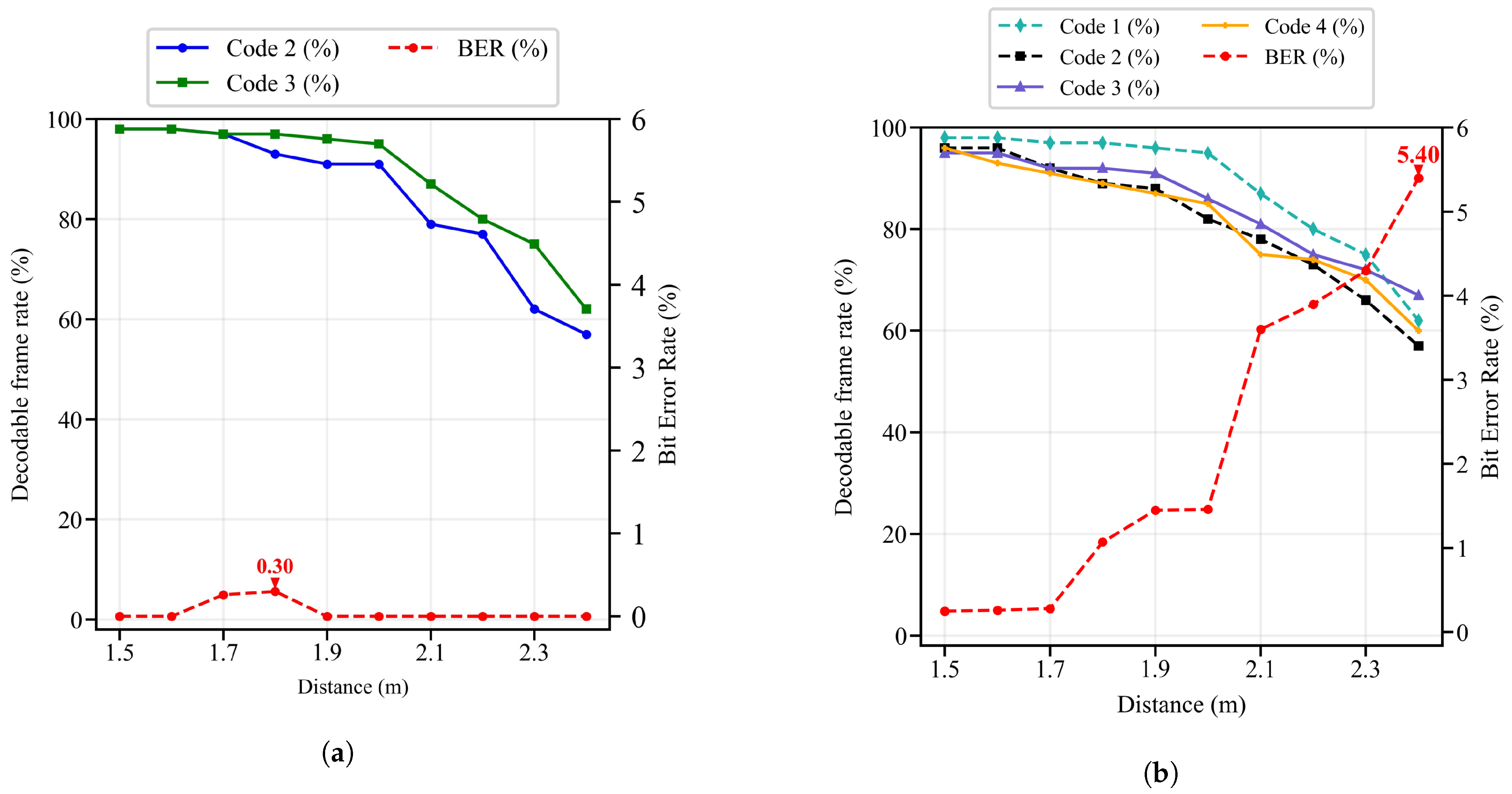
To investigate the impact of simultaneous multi-LED transmission on system performance, experiments were conducted using clusters of two or more LEDs operating at varying flicker frequencies. As depicted in Figure 16a,b, simultaneous data transmission by multiple LEDs exhibited negligible degradation in the decodable frame rate (DFR), which remained stable at approximately 90% within a 2 m range. However, beyond 2.1 m, the DFR demonstrated a pronounced decline, dropping to suboptimal levels. In contrast, the bit error rate (BER) displayed significant divergence across scenarios. For clusters operating at 16 kHz, the BER remained below 1% across all tested distances, indicating robust noise immunity. Conversely, at 20 kHz, the BER exhibited a marked increase beyond 1.8 m, exceeding 5% at 2.4 m. This degradation is attributed to the inverse relationship between modulation frequency and pixel occupancy per data bit: higher frequencies reduce the spatial resolution of individual bits, making them susceptible to environmental noise. Consequently, the resultant blurring of dark–light transitions between adjacent pixels compromised decoding precision, particularly at extended transmission distances.
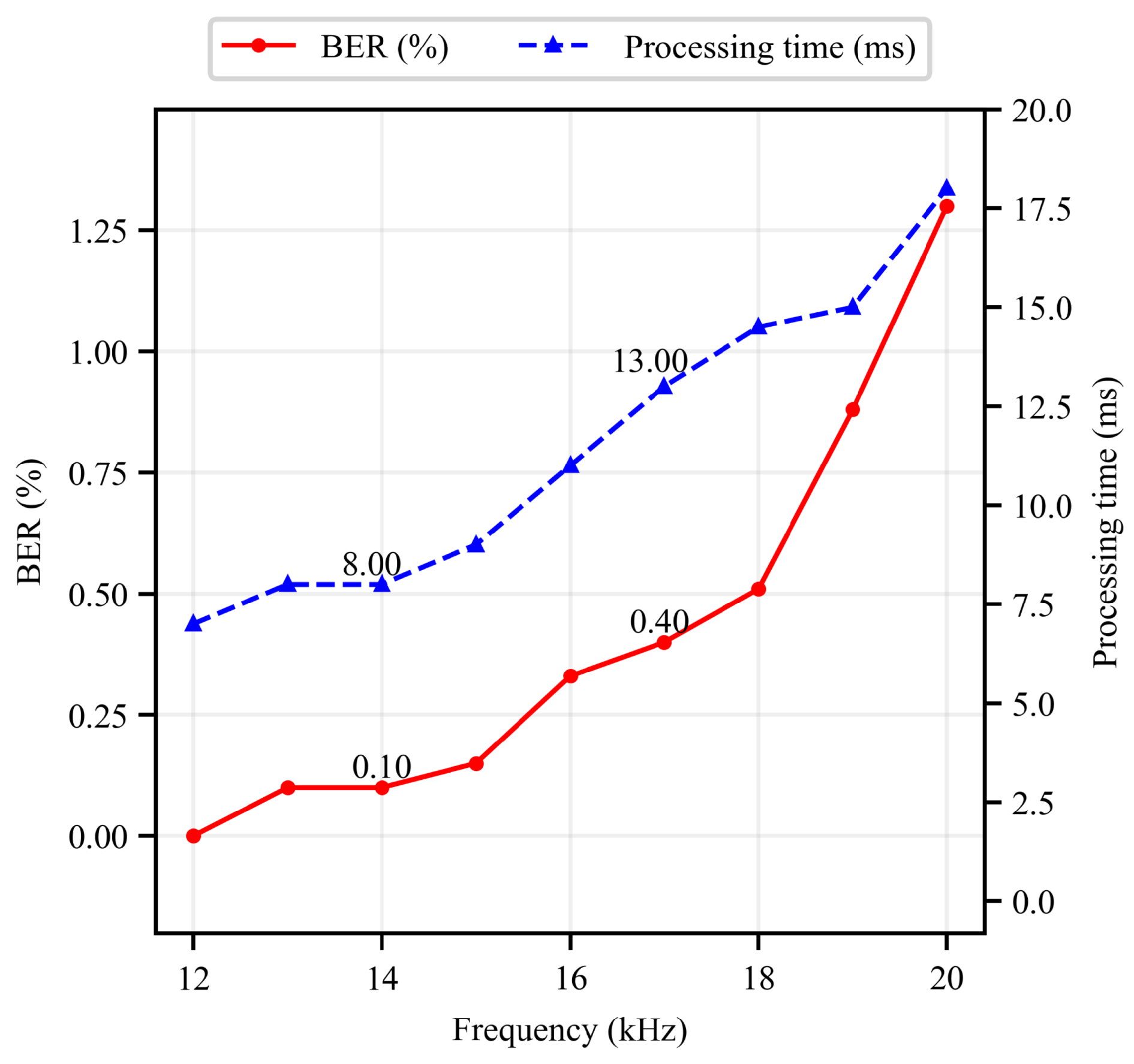
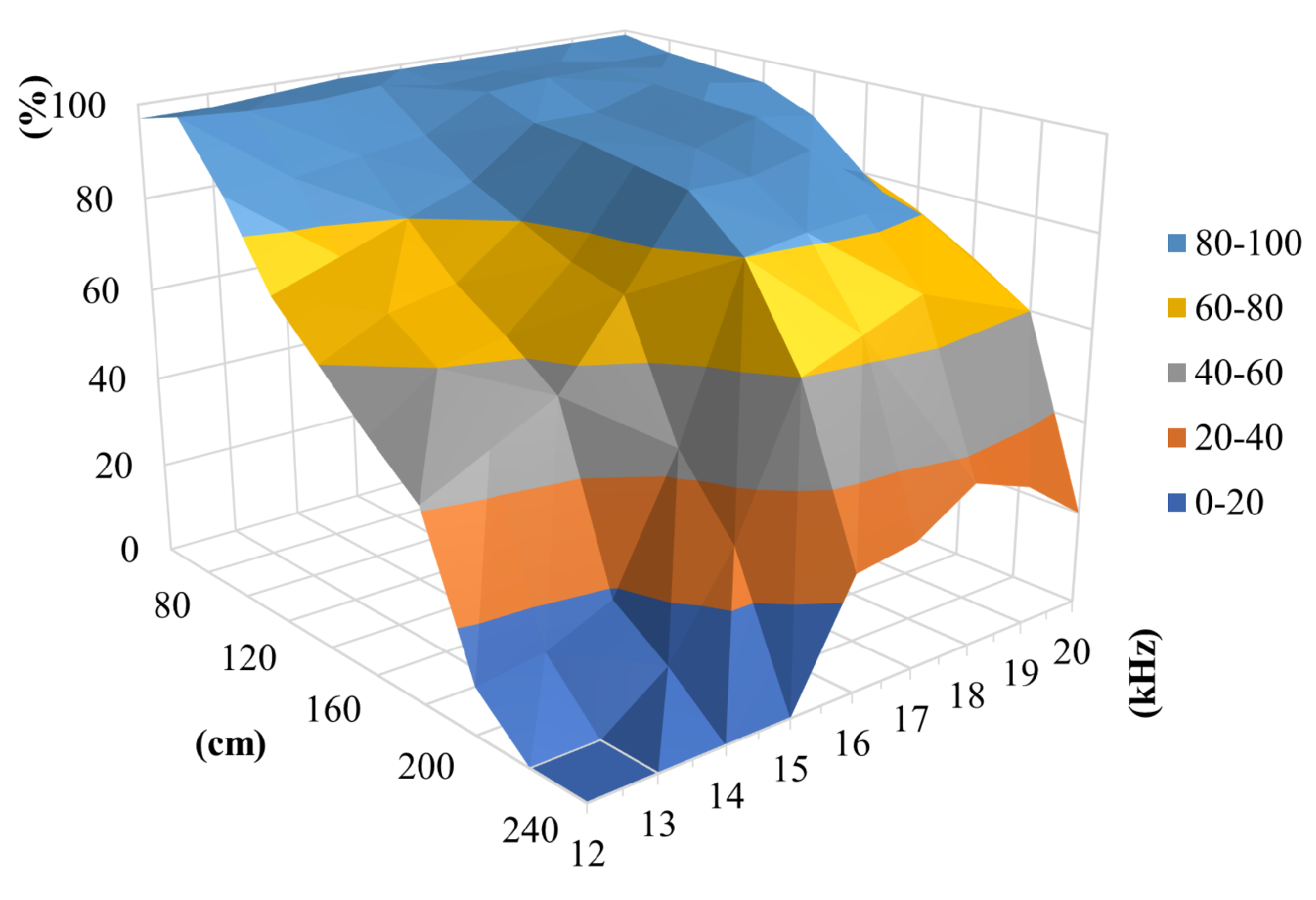
Optimizing LED flicker frequency for ID data transmission in VLP systems necessitates a comprehensive evaluation of frame processing latency and error rates to balance positioning efficiency and reliability. Experimental evaluations conducted at a 2-m transmission distance, as shown in Figure 17, revealed a proportional increase in both processing time and BER with rising frequencies within 12–20 kHz, attributable to heightened bit density per image frame and amplified environmental noise interference. Despite these trends, the BER remained consistently below 2%, and frame processing time was capped at 20 ms, demonstrating low-latency performance and robust accuracy, critical attributes for real-time VLP applications. However, the DFR exhibited non-linear behavior across the tested frequency spectrum, as shown in Figure 18. The 16–18 kHz range yielded optimal DFR performance, sustaining rates above 80%, whereas frequencies outside this interval resulted in subpar decoding stability. This divergence underscores the interplay between modulation frequency and spatial resolution: higher frequencies reduce pixel occupancy per data bit, exacerbating susceptibility to noise-induced decoding failures. Consequently, the MPPM technique is best implemented within the 16–18 kHz range, corresponding to 13–15 ms latency, as it harmonizes high DFR retention with manageable BER and latency, thereby maximizing system efficacy in practical VLP deployments.

5.2.2. Position Accuracy

In this part, we focus on the evaluation of localization performance under the impact of receiver orientation. The positioning accuracy of the proposed system was evaluated across smartphone angular orientations relative to the LED, with device heights set at 125 cm, 130 cm, and 135 cm to simulate handheld usage (corresponding to LED distances of 165–175 cm). To evaluate accuracy in this setup, 225 sampling locations were evenly distributed over a 70 cm × 70 cm plane, with a 10 cm division along both the O x and O y axes. In addition, based on prior flicker frequency optimization, 18 kHz was selected for its superior transmission performance and was employed throughout positioning experiments.
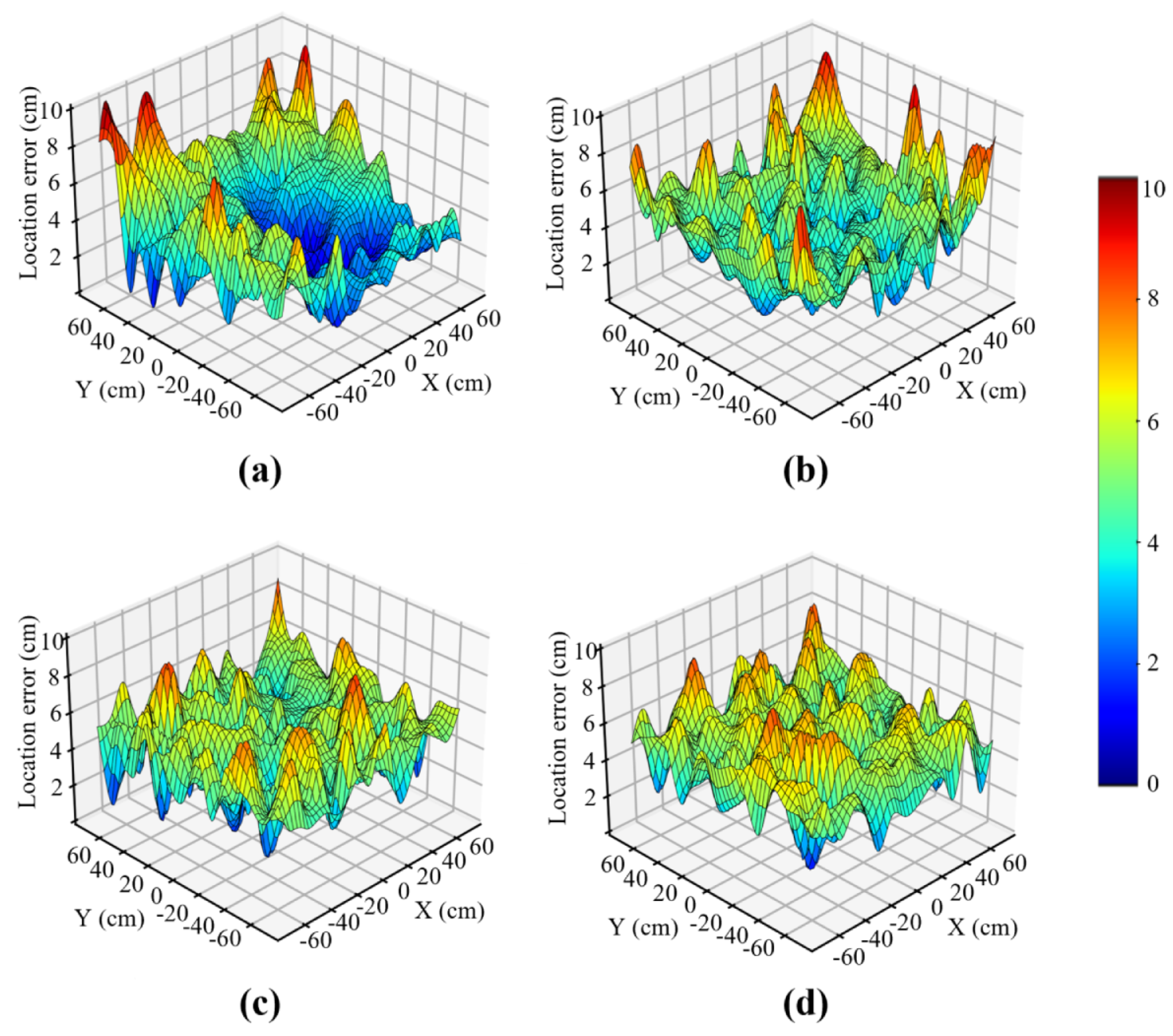
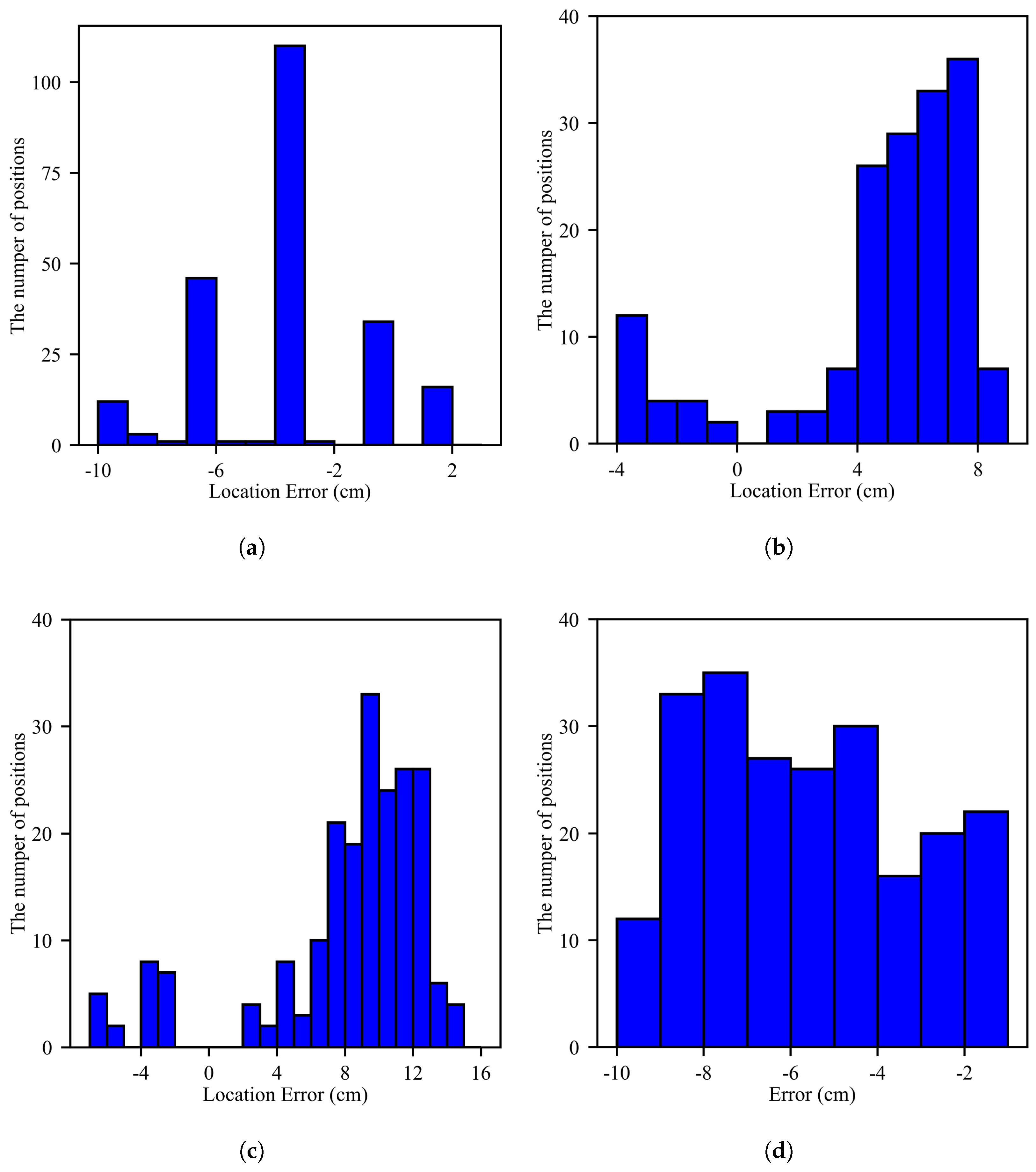
Figure 19 illustrates the 2D positioning error at different smartphone heights (125 cm, 130 cm, and 135 cm) under varying rotational configurations. In the first experiment, the smartphone was placed parallel to the ground (baseline position) without tilt angles ( α = β = γ = 0 ). The results were specific coordinates in 3D space, calculated and compared with reference coordinates, as illustrated in Figure 19a. The 2D positioning error was smaller near the center, within 4–6 cm, and increased toward peripheral regions with errors exceeding 6 cm but remaining below 10 cm. Along the O z axis, errors were concentrated in three ranges: 1–2 cm, 3–4 cm, and 6–7 cm, as shown in Figure 20a, with only a negligible number of points reaching 10 cm.
In the second experiment, the system was evaluated with β = 20 ° while maintaining α = γ = 0 , simulating a user tilting the phone toward their eyes. The 2D error distribution is similar to that in the first experiment, as shown in Figure 19b. Despite the change in tilt angle, the error along the O z axis did not exceed 10 cm, as shown in Figure 20b. To further evaluate practical scenarios, another experiment was conducted where the smartphone was rotated with α = 0 , β = 20 ° , and γ = 10 ° . The 2D error remained below 7 cm, as shown in Figure 19c, but O z -axis errors increased to 10–15 cm, as shown in Figure 20c. Notably, real-world applications prioritize 2D positional accuracy over vertical distance.
In the final scenario, the yaw angle was set to 90 ° , while β and γ remained unchanged. This tested positioning accuracy when the phone’s rotation deviated from the Y-axis. Figure 19d shows that the 2D error stayed below 7 cm, while the O z -axis errors ranged from 4 to 10 cm, as illustrated in Figure 20d. Overall, rotation around the O z axis had minimal impact on 2D positioning compared to the baseline.
Next, we analyze the cumulative distribution functions (CDFs) of positioning errors across various rotation angles in both the 2D plane and 3D space, as shown in Figure 21. In the 2D plane, as illustrated in Figure 21a, the non-rotational experiment yields the steepest CDF curve with minimal errors, demonstrating superior accuracy. The introduction of a pitch angle ( α = γ = 0 ° , β = 20 ° ) significantly decreases accuracy, while the combination of multiple rotation angles ( α = 0 ° , β = 20 ° , γ = 10 ° ) produces the largest errors in the range of 8–10 cm due to complex distortional effects. Notably, rotation around a single axis, even at large angles ( α = 90 ° , β = γ = 0 ° ), results in better positioning performance than multiple smaller rotations across different axes, indicating that multi-axial rotational complexity more severely impacts accuracy than single-axis rotation magnitude. Figure 21b reveals the system’s performance in 3D space, where the non-rotational configuration ( α = β = γ = 0 ° ) achieves optimal accuracy with approximately 60% of measurements exhibiting errors below 7.5 cm. Single-axis rotation scenarios demonstrate considerably degraded performance, with only about 50% of measurements maintaining errors below 7.5 cm. The most significant performance deterioration occurs with multi-angular rotation ( α = 0 ° , β = 20 ° , γ = 10 ° ), where 50% of measurements produce errors exceeding 10 cm. These results empirically establish that rotational complexity, particularly involving multiple axes, constitutes a critical factor affecting the positioning accuracy of the proposed system.

6. Discussion

The proposed system addresses critical challenges in visible light positioning (VLP) by combining high-efficiency MPPM modulation with smartphone sensor fusion. Compared to conventional methods, such as On–Off Keying (OOK), the framework achieves superior performance in both range and stability, reducing latency to 30 ms while maintaining sub-10 cm horizontal accuracy. This represents a significant advancement over existing smartphone-based solutions, which often trade precision for processing speed or struggle with orientation-induced errors. By dynamically integrating accelerometer and magnetometer data, the system mitigates tilt-related distortions, a persistent issue in prior work, thereby enhancing robustness for real-world handheld use.
However, several limitations must be acknowledged. First, the experiments were conducted under controlled laboratory conditions, which may not fully capture the complexities of dynamic environments, such as occlusions, multi-path reflections, or fluctuating ambient light. In particular, the system’s performance under extreme variations in ambient light, such as direct sunlight or flickering artificial sources, was not explicitly quantified because testing focused on stable office-like lighting conditions. MPPM’s pulse-based encoding and DBSCAN clustering provide robustness by detecting high-contrast pulses and adaptively grouping LED projections; however, extreme conditions could reduce the SNR, potentially lowering the DFR to 90–93% and increasing 2D errors to 12–15 cm based on moderate noise trends. Sensor fusion with accelerometer and magnetometer data helps stabilize decoding during sudden illumination changes by correcting for device orientation, serving as a safeguard against failures. Second, the reliance on specific smartphone hardware and LED configurations raises concerns about generalizability. Variations in camera resolution, sensor calibration, or LED driver specifications across devices may necessitate recalibration or adaptive algorithms to ensure consistent performance. Third, the 2.4 m operational range, though improved over traditional methods, remains insufficient for large-scale deployments like warehouses or airports. Extending coverage without compromising accuracy or latency will require further optimization of modulation parameters or hybrid architectures. Similarly, the algorithm’s performance at distances beyond 2.4 m was not evaluated, as the simulation focused on typical office ceiling heights of 2.5–3 m. At longer distances, reduced LED signal intensity and increased noise could increase 2D positioning errors to 12–15 cm and reduce the DFR to 90–95%, based on the observed performance trend from 1.5 to 2.4 m. The algorithm’s MPPM modulation and DBSCAN clustering remain adaptable, but adjustments to pulse width or brightness may be needed to maintain accuracy.
Additionally, the proposed VLP algorithm was optimized for office-style buildings, where fixed, ceiling-mounted LED configurations with 35 cm inter-LED spacing are standard, ensuring a robust line of sight (LOS) and compatibility with workplace lighting designs [35]. This planar arrangement, while ideal for typical office environments, may limit applicability in settings with alternative transmitter geometries, such as spherical arrangements for curved ceilings or square grids for dense lighting deployments. A spherical geometry could introduce varying LED projection angles, potentially increasing 3D positioning errors to 15–20 cm compared to the baseline 16 cm, due to challenges in maintaining consistent stripe widths (Equation (2)). A square grid with closely spaced LEDs might risk crosstalk, reducing the decoding success rate (DFR) below the baseline 97% if clustering parameters are not adjusted. The algorithm’s reliance on DBSCAN clustering and MPPM encoding makes it adaptable to such geometries, provided inter-LED spacing stays within 35–50 cm [35]. Similarly, the algorithm’s performance for mobile users with varying speeds was tested under controlled conditions, assuming static or slow-moving users (e.g., walking at 1–1.5 m/s), typical of office environments. Higher user speeds (e.g., >2 m/s) or dynamic motion patterns, such as hand tremors, could introduce motion blur or sensor noise, potentially increasing 2D positioning errors to 12–15 cm and reducing the DFR below 97% due to inconsistent stripe detection. Our ongoing research is investigating these effects across diverse age groups, measuring the impact of walking speeds (0.5–3 m/s) and hand tremors on accuracy and latency, with results to be published in a forthcoming study.
Future research should prioritize bridging these gaps. Quantitative evaluation of alternative geometries, such as spherical or square LED arrangements, could extend the system’s applicability to diverse architectural designs, complementing its optimization for office environments. Testing with mobile users at varying speeds and incorporating hand tremor data from diverse age groups will further enhance robustness, building on our ongoing study’s findings. Exploring performance at distances beyond 2.4 m, particularly for larger office spaces or non-office environments, will validate scalability and guide optimization of modulation parameters. Testing in real-world environments with diverse lighting conditions and obstructions will validate the system’s practicality. Adaptive modulation schemes could adjust brightness and data rates dynamically to balance illumination requirements with communication efficiency across varying distances. Integrating machine learning models or advanced filtering techniques may further enhance noise immunity and motion robustness, particularly for rapid device movements. Additionally, addressing Android fragmentation through standardized APIs or platform-agnostic software layers would broaden accessibility. These steps will solidify the framework’s viability for applications ranging from indoor navigation to augmented reality, ultimately advancing VLP toward widespread adoption in smart infrastructure.

7. Conclusions

This study presents a high-precision indoor positioning system that integrates multi-pulse position modulation with smartphone-based sensor fusion, achieving real-time localization with centimeter-level accuracy. The proposed framework demonstrates a decoding success rate of over 97% at distances up to 2.4 m and processes data at 30 frames per second with a latency of 30 ms, significantly advancing the performance benchmarks for visible light positioning. By dynamically compensating for device orientation through accelerometer and magnetometer data, the system reduces vertical positioning errors to under 16 cm, even under non-ideal user handling conditions. Its compatibility with existing LED infrastructure standards ensures cost-effective scalability, making it suitable for deployment in smart buildings, healthcare facilities, and industrial environments. Future work will prioritize enhancing environmental robustness, extending operational range, and addressing cross-device compatibility challenges to facilitate widespread adoption in real-world settings. These contributions establish a critical foundation for next-generation indoor navigation systems that balance precision, speed, and practicality.

Author Contributions

Conceptualization, D.Q.N. and H.N.N.; data curation, D.Q.N.; formal analysis, D.Q.N.; funding acquisition, H.N.N.; project administration, H.N.N.; software, D.Q.N.; supervision, H.N.N.; validation, D.Q.N.; writing—original draft, D.Q.N.; writing—review and editing, D.Q.N. and H.N.N. All authors have read and agreed to the published version of the manuscript.

Funding

This research received no external funding.

Institutional Review Board Statement

Not applicable.

Informed Consent Statement

Not applicable.

Data Availability Statement

The data are contained within the article.

Conflicts of Interest

The authors declare no conflicts of interest.

References

  1. Vu, T.L.; Nguyen, T.; Kim, C.S.; Sin, E.B.; Jeong, J.; Jang, Y.M. Survey of indoor optical camera communication (OCC) systems for the Internet of lights. In Proceedings of the 2017 International Conference on Information and Communication Technology Convergence (ICTC), Jeju Island, Republic of Korea, 18–20 October 2017; pp. 700–703. [Google Scholar] [CrossRef]
  2. Dawood, M.A.; Saleh, S.S.; El-Badawy, E.S.A.; Aly, M.H. A comparative analysis of localization algorithms for visible light communication. Opt. Quantum Electron. 2021, 53, 108. [Google Scholar] [CrossRef]
  3. Nguyen, C.T.; Saputra, Y.M.; Huynh, N.V.; Nguyen, N.T.; Khoa, T.V.; Tuan, B.M.; Nguyen, D.N.; Hoang, D.T.; Vu, T.X.; Dutkiewicz, E.; et al. A Comprehensive Survey of Enabling and Emerging Technologies for Social Distancing—Part I: Fundamentals and Enabling Technologies. IEEE Access 2020, 8, 153479–153507. [Google Scholar] [CrossRef] [PubMed]
  4. Dardari, D.; Closas, P.; Djuric, P.M. Indoor tracking: Theory, methods, and technologies. IEEE Trans. Veh. Technol. 2015, 64, 1263–1278. [Google Scholar] [CrossRef]
  5. Ciftler, B.S.; Kadri, A.; Guvenc, I. Fundamental bounds on RSS-based wireless localization in passive UHF RFID systems. In Proceedings of the 2015 IEEE Wireless Communications and Networking Conference (WCNC), New Orleans, LA, USA, 9–12 March 2015; pp. 1356–1361. [Google Scholar] [CrossRef]
  6. Armstrong, J.; Sekercioglu, Y.; Neild, A. Visible light positioning: A roadmap for international standardization. IEEE Commun. Mag. 2013, 51, 68–73. [Google Scholar] [CrossRef]
  7. Lin, B.; Ghassemlooy, Z.; Lin, C.; Tang, X.; Li, Y.; Zhang, S. An Indoor Visible Light Positioning System Based on Optical Camera Communications. IEEE Photonics Technol. Lett. 2017, 29, 579–582. [Google Scholar] [CrossRef]
  8. Yang, S.H.; Kim, H.S.; Son, Y.H.; Han, S.K. Three-dimensional visible light indoor localization using AOA and RSS with multiple optical receivers. J. Light. Technol. 2014, 32, 2480–2485. [Google Scholar] [CrossRef]
  9. Guan, W.; Wu, Y.; Wen, S.; Chen, H.; Yang, C.; Chen, Y.; Zhang, Z. A novel three-dimensional indoor positioning algorithm design based on visible light communication. Opt. Commun. 2017, 392, 282–293. [Google Scholar] [CrossRef]
  10. Kim, D.; Park, J.K.; Kim, J.T. Three-Dimensional VLC Positioning System Model and Method Considering Receiver Tilt. IEEE Access 2019, 7, 132205–132216. [Google Scholar] [CrossRef]
  11. Jeong, E.M.; Yang, S.H.; Kim, H.S.; Han, S.K. Tilted receiver angle error compensated indoor positioning system based on visible light communication. Electron. Lett. 2013, 49, 888–890. [Google Scholar] [CrossRef]
  12. Xie, B.; Chen, K.; Tan, G.; Lu, M.; Liu, Y.; Wu, J.; He, T. LIPS: A Light Intensity Based Positioning System For Indoor Environments. ACM Trans. Sens. Netw. 2016, 12, 1–27. [Google Scholar] [CrossRef]
  13. Li, Z.; Yang, A.; Lv, H.; Feng, L.; Song, W. Fusion of Visible Light Indoor Positioning and Inertial Navigation Based on Particle Filter. IEEE Photonics J. 2017, 9, 1–13. [Google Scholar] [CrossRef]
  14. Yasir, M.; Ho, S.W.; Vellambi, B.N. Indoor positioning system using visible light and accelerometer. J. Light. Technol. 2014, 32, 3306–3316. [Google Scholar] [CrossRef]
  15. Nguyen, Q.D.; Nguyen, N.H. Mobile Application for Visible Light Communication Systems: An Approach for Indoor Positioning. Photonics 2024, 11, 293. [Google Scholar] [CrossRef]
  16. Rajagopal, S.; Roberts, R.; Lim, S.K. IEEE 802.15.7 visible light communication: Modulation schemes and dimming support. IEEE Commun. Mag. 2012, 50, 72–82. [Google Scholar] [CrossRef]
  17. Gu, Y.; Lo, A.; Niemegeers, I. A survey of indoor positioning systems for wireless personal networks. IEEE Commun. Surv. Tutor. 2009, 11, 13–32. [Google Scholar] [CrossRef]
  18. Do, T.H.; Yoo, M. An in-depth survey of visible light communication based positioning systems. Sensors 2016, 16, 678. [Google Scholar] [CrossRef]
  19. Sato, T.; Shimada, S.; Murakami, H.; Watanabe, H.; Hashizume, H.; Sugimoto, M. ALiSA: A Visible-Light Positioning System Using the Ambient Light Sensor Assembly in a Smartphone. IEEE Sens. J. 2022, 22, 4989–5000. [Google Scholar] [CrossRef]
  20. Hussain, B.; Wang, Y.; Chen, R.; Cheng, H.C.; Yue, C.P. LiDR: Visible-Light-Communication-Assisted Dead Reckoning for Accurate Indoor Localization. IEEE Internet Things J. 2022, 9, 15742–15755. [Google Scholar] [CrossRef]
  21. Amari, K.; Keche, M. Accurate indoor visible light positioning method using four LEDs and a smartphone camera. Optik 2025, 331, 172346. [Google Scholar] [CrossRef]
  22. Kuo, Y.S.; Pannuto, P.; Hsiao, K.J.; Dutta, P. Luxapose: Indoor positioning with mobile phones and visible light. In Proceedings of the Annual International Conference on Mobile Computing and Networking, MOBICOM. Association for Computing Machinery, Maui, HI, USA, 7–11 September 9 2014; pp. 447–458. [Google Scholar] [CrossRef]
  23. Wang, Z.; Yang, Z.; Zhang, J.; Huang, C.; Zhang, Q. Wearables Can Afford: Light-weight Indoor Positioning with Visible Light. In Proceedings of the MobiSys 2015—Proceedings of the 13th Annual International Conference on Mobile Systems, Applications, and Services. Association for Computing Machinery, Florence, Italy, 18–22 May 2015; p. 465. [Google Scholar] [CrossRef]
  24. Pathak, P.H.; Feng, X.; Hu, P.; Mohapatra, P. Visible Light Communication, Networking, and Sensing: A Survey, Potential and Challenges. IEEE Commun. Surv. Tutor. 2015, 17, 2047–2077. [Google Scholar] [CrossRef]
  25. Koonen, T. Indoor Optical Wireless Systems: Technology, Trends, and Applications. J. Light. Technol. 2018, 36, 1459–1467. [Google Scholar] [CrossRef]
  26. Cahyadi, W.A.; Chung, Y.H.; Ghassemlooy, Z.; Hassan, N.B. Optical camera communications: Principles, modulations, potential and challenges. Electronics 2020, 9, 1339. [Google Scholar] [CrossRef]
  27. Kozawa, Y.; Habuchi, H. Enhancement of Optical Wireless Multi-Pulse PPM. In Proceedings of the IEEE GLOBECOM 2008—2008 IEEE Global Telecommunications Conference, New Orleans, LA, USA, 30 November–4 December 2008; pp. 1–5. [Google Scholar] [CrossRef]
  28. Xu, F.; Khalighi, M.A.; Bourennane, S. Coded PPM and Multipulse PPM and Iterative Detection for Free-Space Optical Links. J. Opt. Commun. Netw. 2009, 1, 404. [Google Scholar] [CrossRef]
  29. Siddique, A.B.; Tahir, M. Joint rate-brightness control using variable rate MPPM for LED based visible light communication systems. IEEE Trans. Wirel. Commun. 2013, 12, 4604–4611. [Google Scholar] [CrossRef]
  30. Sugiyama, H.; Nosu, K. MPPM: A method for improving the band-utilization efficiency in optical PPM. J. Light. Technol. 1989, 7, 465–472. [Google Scholar] [CrossRef]
  31. Nguyen, D.T.; Park, Y. Data rate enhancement of optical camera communications by compensating inter-frame gaps. Opt. Commun. 2017, 394, 56–61. [Google Scholar] [CrossRef]
  32. Xu, J.; Gong, C.; Xu, Z. Experimental indoor visible light positioning systems with centimeter accuracy based on a commercial smartphone camera. IEEE Photonics J. 2018, 10, 1–17. [Google Scholar] [CrossRef]
  33. Soltani, M.D.; Purwita, A.A.; Zeng, Z.; Haas, H.; Safari, M. Modeling the random orientation of mobile devices: Measurement, analysis and LiFi Use Case. IEEE Trans. Commun. 2019, 67, 2157–2172. [Google Scholar] [CrossRef]
  34. Tuck, K. Tilt Sensing Using Linear Accelerometers. In Freescale Semiconductor Application Note AN3107; Freescale Semiconductor Inc.: Austin, TX, USA, 2007. [Google Scholar]
  35. Nguyen, N.H.; Pham-Nguyen, L.; Thi, H.N.; Viet, S.N.; Lan, H.N.T.; Si, H.H. Performance Analysis and Experiment of Data Transmission Rate of LEDs in Optical Camera Communication for Indoor Positioning System. In Proceedings of the 2022 11th International Conference on Control, Automation and Information Sciences (ICCAIS), Hanoi, Vietnam, 21–24 November 2022; pp. 552–557. [Google Scholar] [CrossRef]
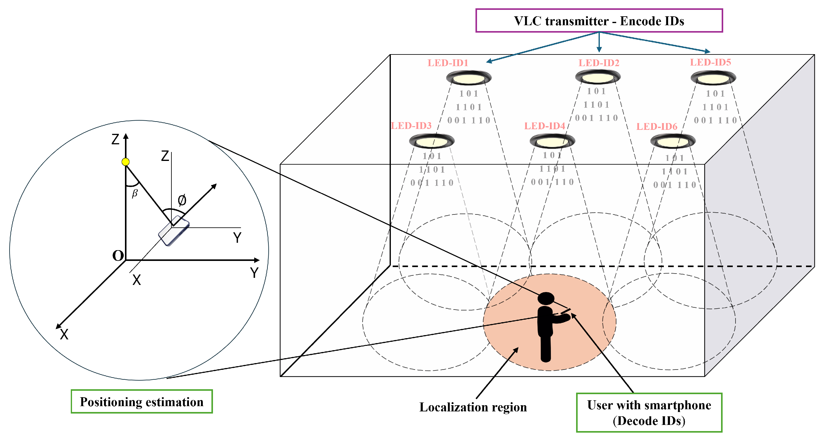
Figure 1. A model of a smart VLP environment.
Photonics 12 00859 g001
Figure 2. Signal frame structure in MPPM.
Photonics 12 00859 g002
Figure 3. Light and dark stripes in OCC.
Photonics 12 00859 g003
Figure 4. Proposed VLP system architecture.
Photonics 12 00859 g004
Figure 5. Diagram showing the principle of the transmitter.
Photonics 12 00859 g005
Figure 6. Transmitter hardware: (a) LED downlights are utilized to locate users in the room or hallway. (b) Driver for LED lights as transmitters.
Photonics 12 00859 g006
Figure 7. The structure of a data frame.
Photonics 12 00859 g007
Figure 8. The camera captures data frames in two cases, as illustrated here: (a) data-loss frames and (b) full-data frames.
Photonics 12 00859 g008
Figure 9. Block diagram of LED decoder.
Photonics 12 00859 g009
Figure 10. LED images from the decoding process: (a) color image; (b) grayscale image; (c) rectangular boundary; (d) coordinates of rectangles; (e) multiple LEDs before clustering; (f) LEDs after clustering.
Photonics 12 00859 g010
Figure 11. Fundamental rotations of mobile phones [33]. (a) Initial position. (b) Yaw rotation with angle γ (z-axis). (c) Pitch rotation with angle ϕ (x-axis). (d) Roll rotation with angle ρ (y-axis).
Photonics 12 00859 g011
Figure 12. Mapping the real coordinate system to the smartphone screen coordinate system.
Photonics 12 00859 g012
Figure 13. Proposed experimental system.
Photonics 12 00859 g013
Figure 14. Image LEDs in the first scenario: (a) one LED is transmitting; (b) one LED is a source of noise in a full-data frame.
Photonics 12 00859 g014
Figure 15. Experimental results of the first scenario.
Photonics 12 00859 g015
Figure 16. Experimental results of the second scenario with multiple LEDs and different flicker frequencies: (a) two transmitter LEDs at 16 kHz, (b) four transmitter LEDs at 20 kHz.
Photonics 12 00859 g016
Figure 17. BER and processing time for different frequencies at a distance of 2 m.
Photonics 12 00859 g017
Figure 18. The decodable frame rate for different frequencies.
Photonics 12 00859 g018
Figure 19. Three-dimensional location error distribution maps for different values of α , β , and γ : (a) α = β = γ = 0 ; (b) α = γ = 0 and β = 20 ; (c) α = 0 , β = 20 , and γ = 10 ; (d) α = 90 , β = γ = 0 .
Photonics 12 00859 g019
Figure 20. Error along the z-axis for different rotation angles: (a) α = β = γ = 0 ; (b) α = γ = 0 and β = 20 ° ; (c) α = 0 , β = 20 ° and γ = 10 ° ; (d) α = 90 ° , β = γ = 0 .
Photonics 12 00859 g020
Figure 21. The CDF of location error for different rotation angles (a) in a 2D plane and (b) in 3D space.
Photonics 12 00859 g021
Table 1. Comparison of smartphone VLP systems.
SchemesTime (ms)AccuracyDistanceMobile Phone
ALISA [19]Not given<0.21 m (90th percentile)1 mGalaxy S10+
LiDR [20]16<0.7 m (mean)1.5 mHuawei P30 Pro
Amari and Keche [21]Not given2 cm (mean)1.6 mNokia Lumia 1020
Luxapose [22]90407 cm2.5 mNokia Lumia 1020
PIXEL [23]120030 cm1–3 mSamsung Galaxy S II
Ours30∼10 cm2.4 mVsmart Aris
Table 2. Summary of MPPM configurations with n = 8 , highlighting the trade-offs between brightness, encoding capacity, and symbol representation.
Parameter r (r)Brightness Index ( r n )No. of Symbols ( C n r )Bits/Symbol ( log 2 C n r )
10.12583
20.250285
30.375566
40.500707
50.625566
60.750285
70.87583
Table 3. LED-ID codes and their modulated payloads.
ID NameSymbol to Encode ( s k )LED-ID CodeModulated LED-ID Code (Payload)
LED-ID1101010101011
LED-ID291001110011
LED-ID360110110101
LED-ID430011101110
Disclaimer/Publisher’s Note: The statements, opinions and data contained in all publications are solely those of the individual author(s) and contributor(s) and not of MDPI and/or the editor(s). MDPI and/or the editor(s) disclaim responsibility for any injury to people or property resulting from any ideas, methods, instructions or products referred to in the content.