1. Introduction
Lidar has been widely used in various applications, including autonomous driving, robot navigation, and drone obstacle avoidance, due to its advantages of a high resolution, high-ranging accuracy, and strong anti-interference capability [
1,
2,
3,
4]. MEMS micromirror laser radar is the most mature semi-solid laser radar at present due to its advantages such as miniaturization and a fast scanning speed. It is also the technical solution for large-scale applications and mass production. However, the main disadvantage of this solution is that the mechanical scanning angle of the micromirror is relatively small, which limits the scanning angle of the radar system, thereby limiting the overall performance and wide application of MEMS scanning laser radar. Therefore, if MEMS laser radar can achieve wide-angle scanning and a broad field of view for detection while maintaining a high scanning speed, high resolution, and long-range detection performance, the application scope of MEMS scanning imaging laser radar will be significantly expanded. It can be applied in various fields, including autonomous driving, target detection and tracking, drones, intelligent logistics, and smart transportation.
In addition to its mature production technology, MEMS scanning mirrors have advantages in terms of their cost and lifespan. MEMS reflectors can modulate, switch the light, and control the phase of the beam [
5,
6,
7,
8,
9]. The small scanning angle restricts the application range of MEMS imaging lidar to a certain extent. Therefore, it is necessary to add auxiliary devices to increase its scanning angle, thereby meeting the needs of practical applications. Currently, there are three primary design methods to increase the system scanning angle: (1) Add scanning devices and utilize multiple MEMS micromirrors for combined scanning. (2) Use a mechanical turntable with a two-dimensional MEMS scanning micromirror for horizontal panoramic scanning. (3) Add an angle expansion optical system to the MEMS scanning micromirror to expand the scanning range.
The solution proposed in reference [
10] involves using multiple MEMS micromirrors for combined scanning. The structure of this solution is simple. However, this solution requires the use of multiple MEMS scanning systems. If the number of combined systems is small, the scanning angle expansion is limited. When multiple systems are used in combination, synchronizing them and stitching together several frame point cloud images presents a significant challenge.
Reference [
11] utilizes a mechanical turntable to drive the MEMS scanning system, enabling it to rotate horizontally and achieve a 360° panoramic scan. This solution is similar to the principle of mechanical rotating laser radar, except that MEMS scanning micromirrors replace the array of light sources and detectors. Therefore, in actual use, it will encounter the same problems as mechanical rotating laser radar, such as its large size and the strong influence of mechanical vibration.
Reference [
12] uses the Snell window effect of the scanning beam to achieve two-dimensional spatial scanning. This solution immerses the MEMS micromirror in a liquid of mineral oil. While allowing the MEMS micromirror to vibrate, the liquid provides the Snell window effect, thereby expanding the scanning angle. Then, the laser spot is converted into plane light through a customized cylindrical prism, which can expand the scanning angle of the MEMS scanning micromirror to 150°. This method significantly expands the scanning angle of the MEMS micromirror; however, since the MEMS micromirror is immersed in liquid, its scanning frequency is greatly limited, and it cannot scan at high speeds. Furthermore, the quality of the beam significantly decreases after it has undergone refraction and reflection in the liquid, and the plane light becomes more divergent after passing through the cylindrical prism, making it difficult to detect distant targets. In summary, the scanning speed and detection distance of this solution are greatly limited. To improve this solution, consider replacing the mineral oil with a curved dome prism to expand the scanning angle of the MEMS micromirror; however, this approach still leaves a problem with large beam divergence.
Reference [
13] proposes a solution that involves placing a positive lens in front of and a negative lens behind the MEMS micromirror to form an inverted Galileo system, thereby expanding the optical scanning angle of the MEMS micromirror. Although this method has a simple structure, the laser beam emitted after passing through the negative lens will increase the beam divergence angle. After long-distance transmission, the light spot becomes significantly larger, and energy dispersion becomes more pronounced. Moreover, the expanded scanning beam is unevenly distributed within the scanning range, resulting in dense beams in the center and sparse beams at the edges, which leads to a decrease in the quality of the point cloud image. Furthermore, when the number of scanning pulse laser beams remains unchanged, the scanning angle increases, resulting in a proportional decrease in the system’s spatial resolution. Moreover, the spatial beam-filling ratio also decreases, which may cause missed detection and a loss of the detection target. This is a problem faced by all solutions that utilize optical systems to expand the scanning angle.
References [
14,
15] are improvements on the above-mentioned positive and negative lens combination system, in which an F-
θ lens is added to the optical system. The F-
θ lens is also called a flat-field focusing lens. Its function is to make the image height of the beam after passing through the lens proportional to the field of view of the lens, ensuring that the laser beam is evenly distributed after passing through the lens. This solution addresses the issue of uneven scanning beams and significantly compresses the divergence angle of the outgoing laser beam, which is beneficial for long-distance transmission. After passing through the F-
θ lens, it is transmitted to a wide-angle lens or a fisheye lens to achieve large-angle scanning. However, due to the addition of the F-
θ lens system, the number of lenses in the entire optical system increases significantly, making system installation more difficult, the cost higher, and the overall system volume larger. Additionally, this solution still has the disadvantage of reducing the system’s spatial resolution.
References [
16,
17] describe a design that uses a MEMS micromirror to move in a spiral trajectory, along with a catadioptric optical system, to achieve panoramic scanning in the horizontal direction. This solution can achieve 360° detection in the horizontal direction, significantly expanding the scanning range, and has a simple structure. However, this solution has high requirements for the alignment of the prism center and the MEMS micromirror center, making the system difficult to assemble and adjust. Furthermore, due to the existence of the refracting and reflecting cone surface, the outgoing light beam will have a large beam divergence in the meridian or sagittal direction. The laser beam, after long-distance transmission, exhibits a flat spot, which significantly affects the energy distribution of the laser beam and the signal-to-noise ratio of the echo signal.
In addition, reference [
18] proposes a new type of wedge structure to expand the system scanning angle. The magnifying structure is composed of a wedge structure made of glass and a reflector with a highly reflective film on the glass (called a back mirror). The incident laser is first reflected by the MEMS reflector to the back mirror, and these beams are referred to as first-order reflected beams. After the first reflection by the back mirror, the laser beam returns to the MEMS mirror. The beam reflected twice by the MEMS micromirror is referred to as a secondary reflected beam. The second-order beam is used as the scanning beam, and the secondary beam can be reflected more times to obtain a higher scanning level. This method does not contain any complex optical lenses or structures. Compared to other methods, the system is more compact and only requires a 1 mm increase in package height. However, this solution requires a larger MEMS reflector surface, and after several reflections, the quality of the outgoing beam deteriorates, and the scanning angle becomes deformed, which does not meet the requirements of high-performance navigation laser radar.
Due to the small mechanical scanning angle of the MEMS scanning micromirror, current technical solutions for achieving large-angle scanning in MEMS laser radar primarily include adding more scanning components, integrating mechanical turntable systems, and using optical angle expansion systems to increase the optical scanning angle of the MEMS micromirror. However, the above technical solutions all have some defects. For example, the quality of the scanning beam decreases after the scanning angle is extended, making it impossible to detect at a long distance. After adding the optical system, the overall system has several disadvantages, including an increased volume and assembly difficulty, as well as a decreased spatial resolution. Therefore, achieving the large-angle scanning of MEMS micromirrors while ensuring system miniaturization, a high spatial resolution, high frame rate, and long-distance detection remains a technical challenge.
Table 1 compares various technical solutions. All of these solutions achieve the expansion of the MEMS scanning mirror. Each solution has its own advantages and disadvantages, allowing users to choose the appropriate solution based on the specific scenario. However, these solutions fail to consider the system’s spatial resolution when considering angle expansion. Many solutions experience a proportional decrease in the spatial resolution after expanding the scanning angle, which is unacceptable for radar systems. The solution proposed in this paper addresses the issue of system spatial resolution while achieving extended scanning angles.
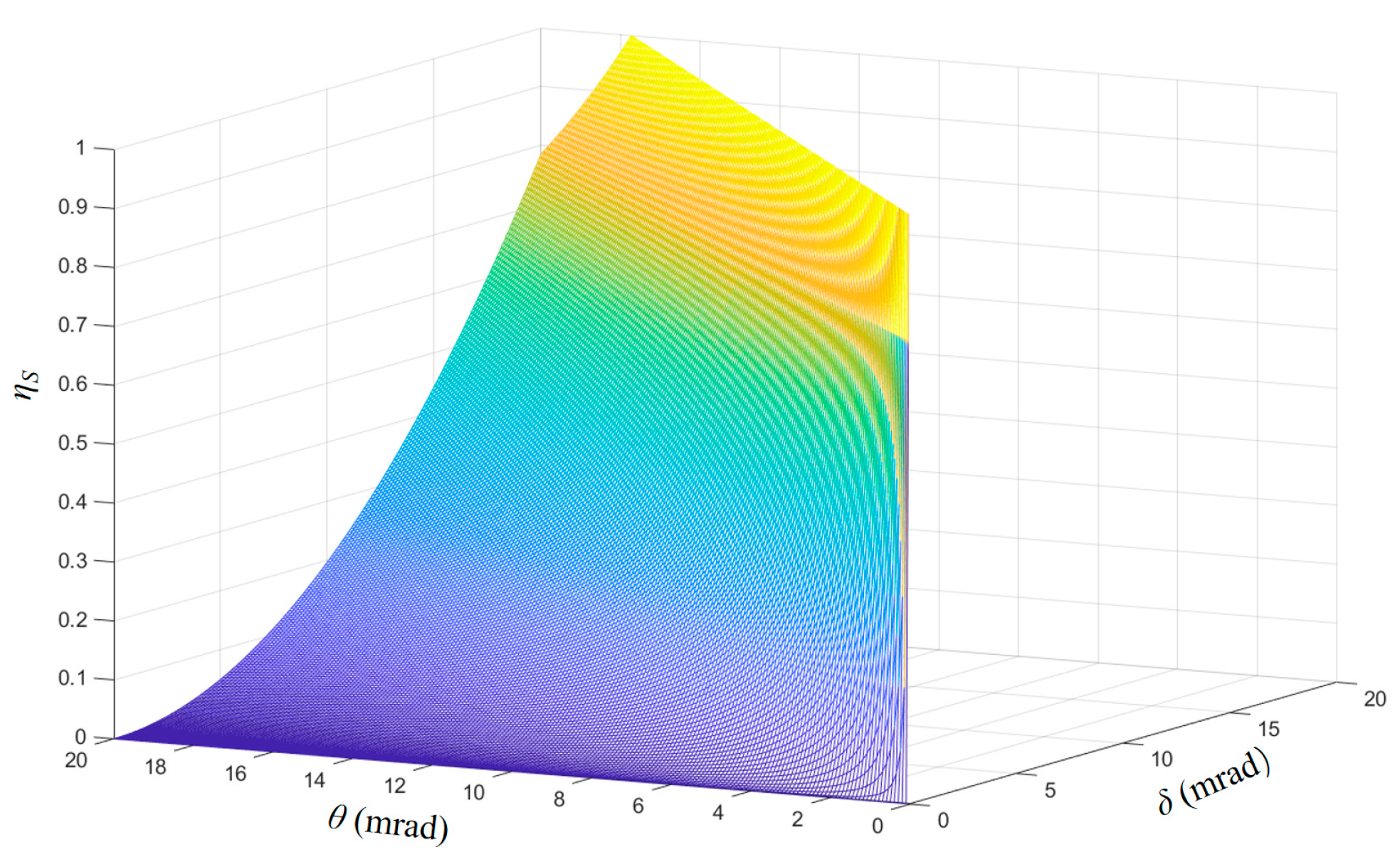
This study proposes a MEMS lidar transmitting optical system with a large angle and high spatial resolution based on an array reflector group and a Fresnel lens. The system uses an array reflector group to convert a sparse array laser beam into a compact array laser beam, overcoming the gaps between beams caused by the mechanical structure. The relationship between the laser beam divergence angle and spatial resolution is analyzed to determine the optimal system parameters and scanning scheme, achieving the highest beam space-filling ratio and maximizing the system’s detection efficiency. The Fresnel lens and a single MEMS micromirror are designed to work together to achieve the large-angle scanning of the array laser beam. While maintaining a high spatial resolution, the system achieves the large-angle scanning of the target area. This paper achieves a large scanning angle, high spatial resolution, and high beam-filling rate simultaneously through the combination of array laser beam, Fresnel prism, and scanning mirror.
3. Optical Design and Parametric Analysis
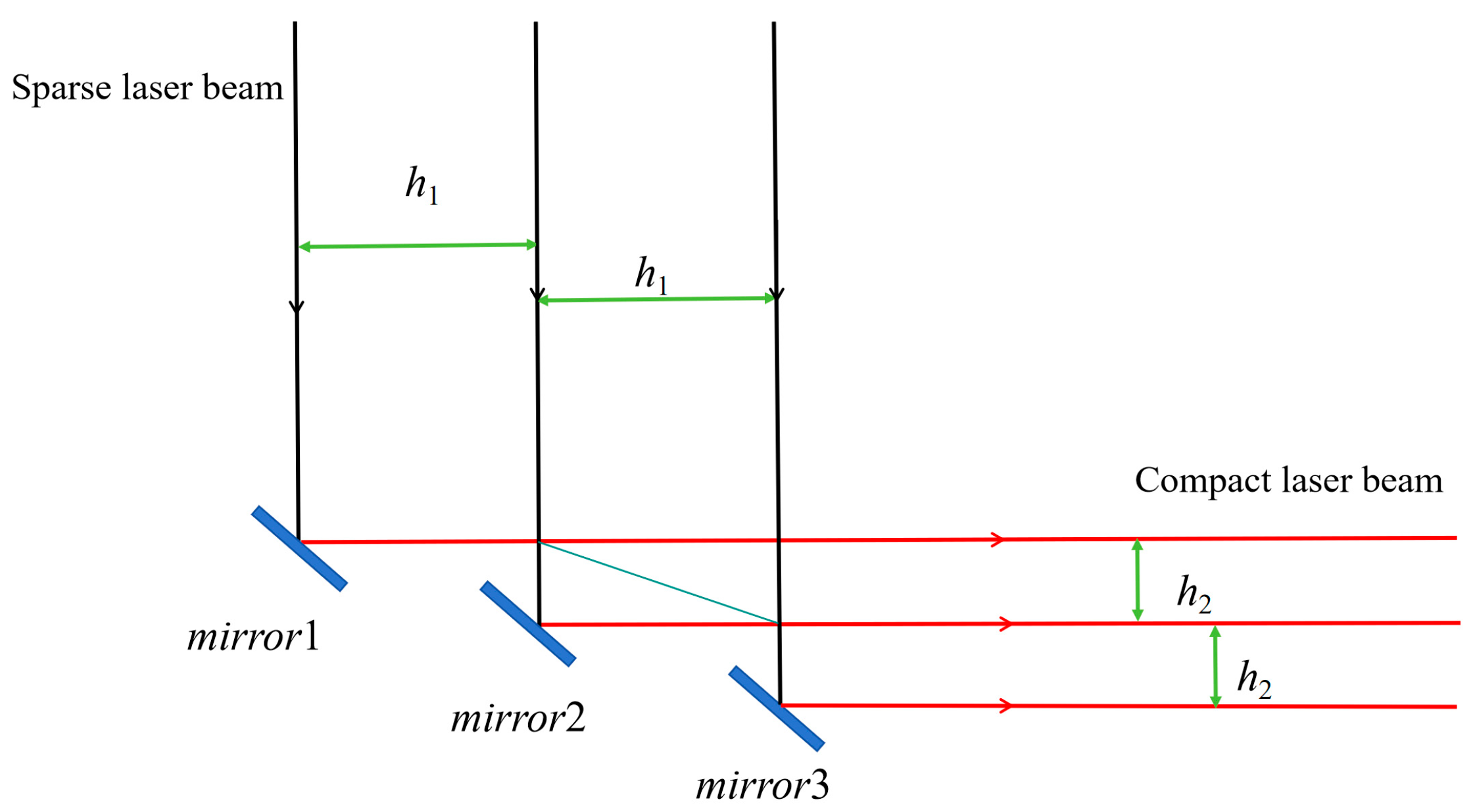
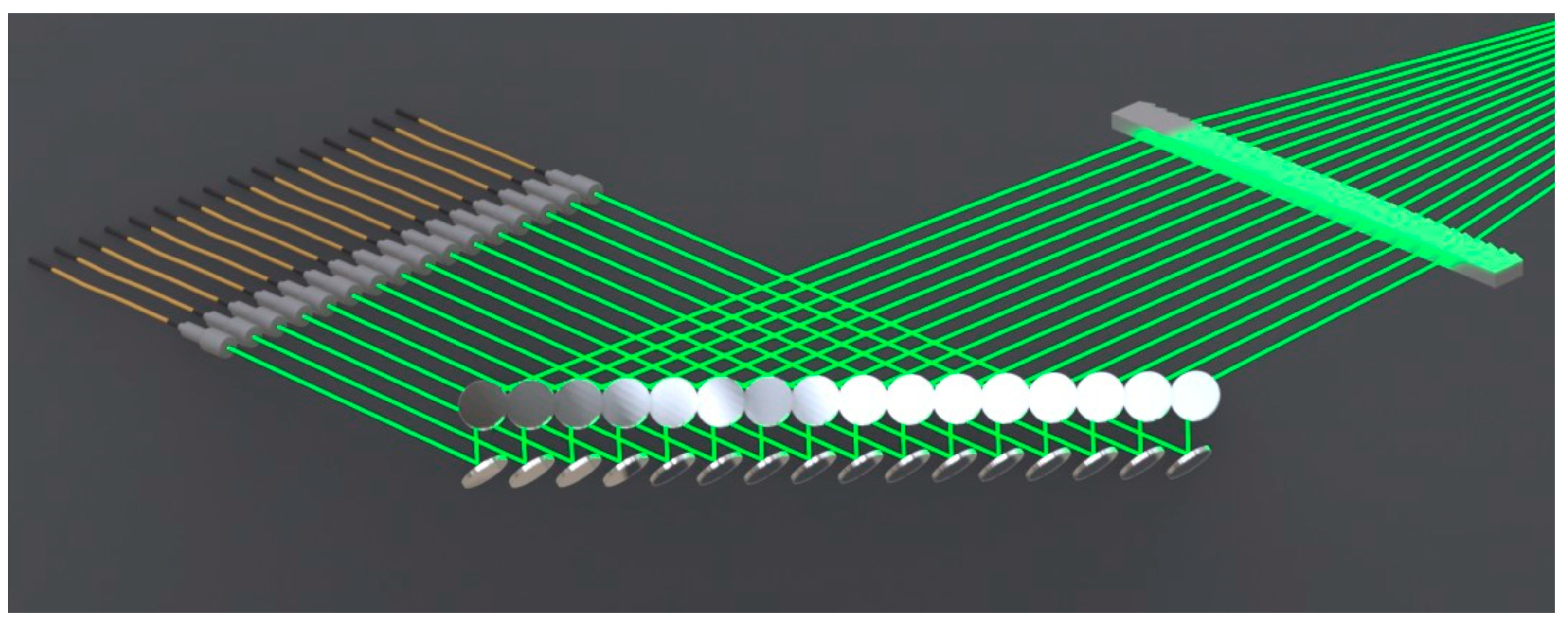
The array reflector group proposed in this project enables the conversion of a sparse beam array into a compact beam array. Its structure and optical path tracing are shown in
Figure 9 and
Figure 10. From the optical path diagram, it can be seen that the sparse array beam is well converted into a compact beam through two sets of array reflectors, and the beam direction is rotated 90°. The spacing of the array laser beam is converted from 8 mm to a compact laser beam array of 3 mm.
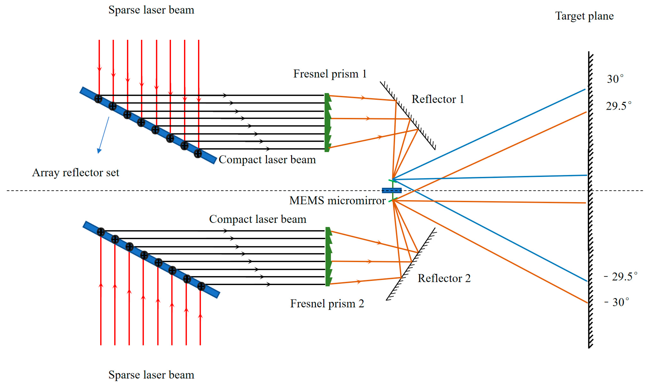
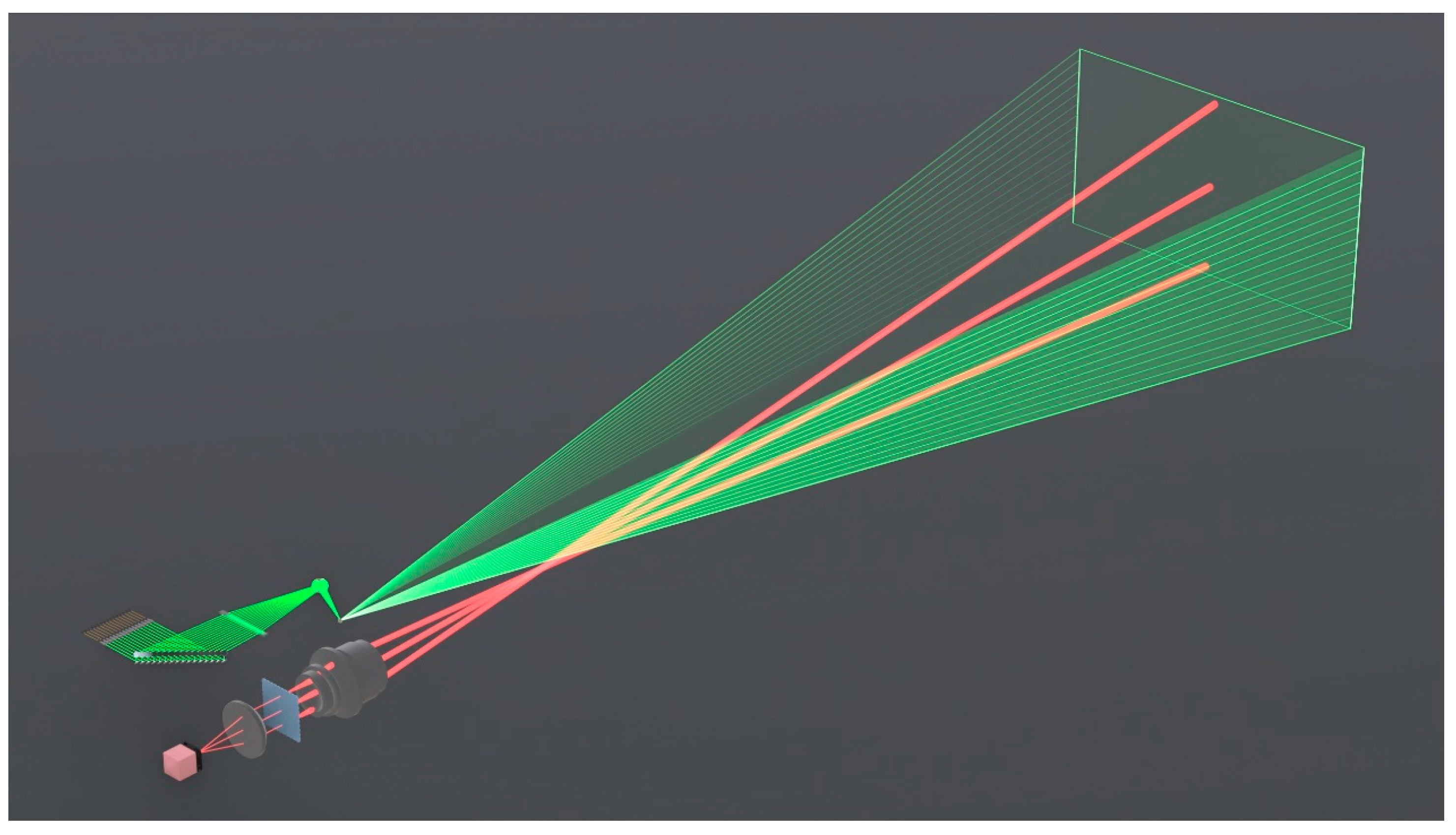
A high-performance Fresnel prism that meets the requirements is designed through theoretical calculation. Using Zemax optical design software for simulation analysis, the overall optical path of the system is shown in
Figure 11. After the array laser beam passes through the Fresnel lens, it remains parallel to the lens. All laser beams are reflected to the MEMS micromirror via a reflector. The MEMS micromirror performs one-dimensional scanning to achieve the large-angle and high-spatial-resolution scanning of the target plane. It can be seen that all laser beams are reflected onto the very small MEMS micromirrors. The beam quality of the laser beams after reflection does not deteriorate, and they remain parallel beams, with different beams distributed at different angles.
The three-dimensional structure of the Fresnel prism is shown in
Figure 12. By designing the angles of different subunits, the precise control of the laser beam array is achieved.
Table 2 lists the angle parameter values.
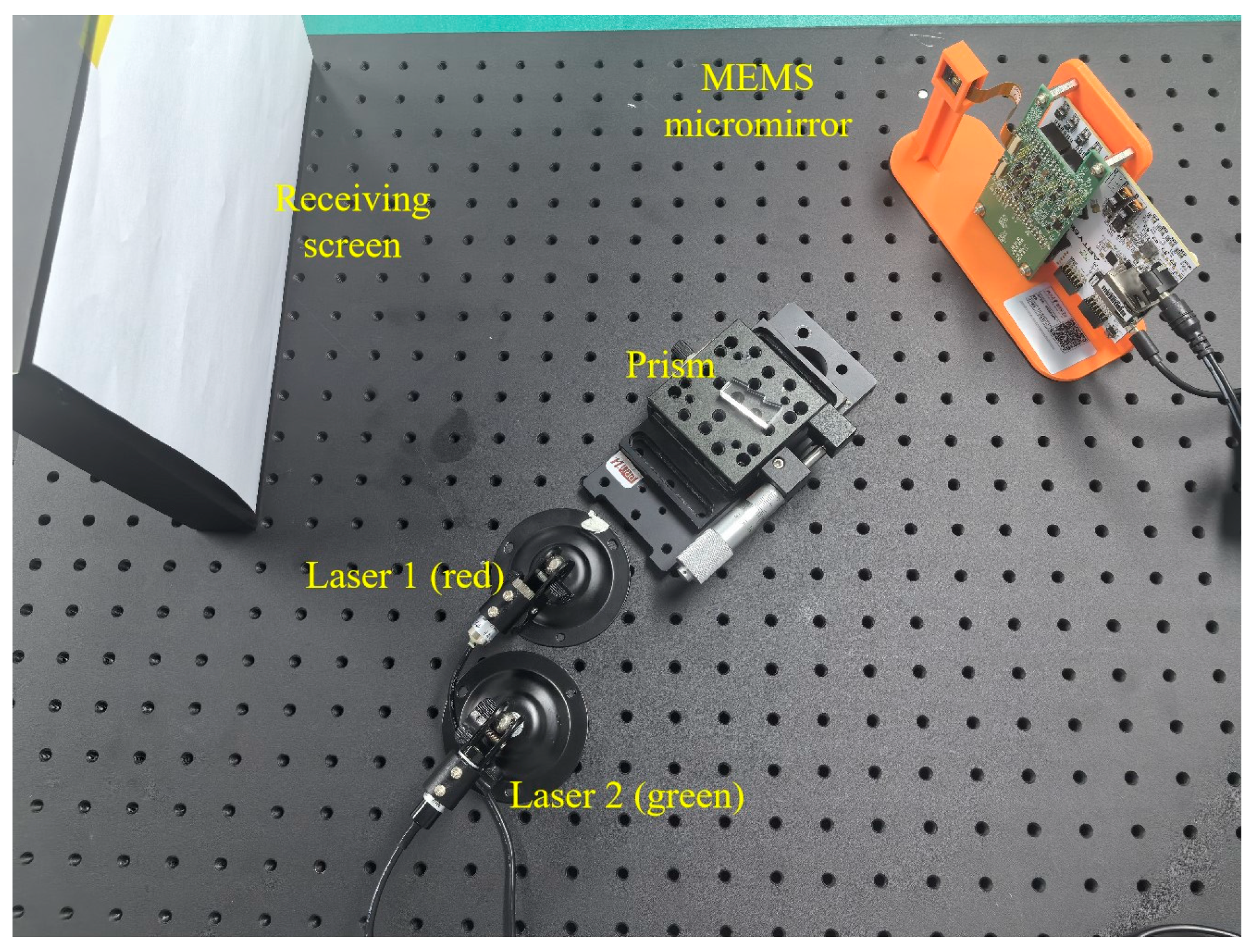
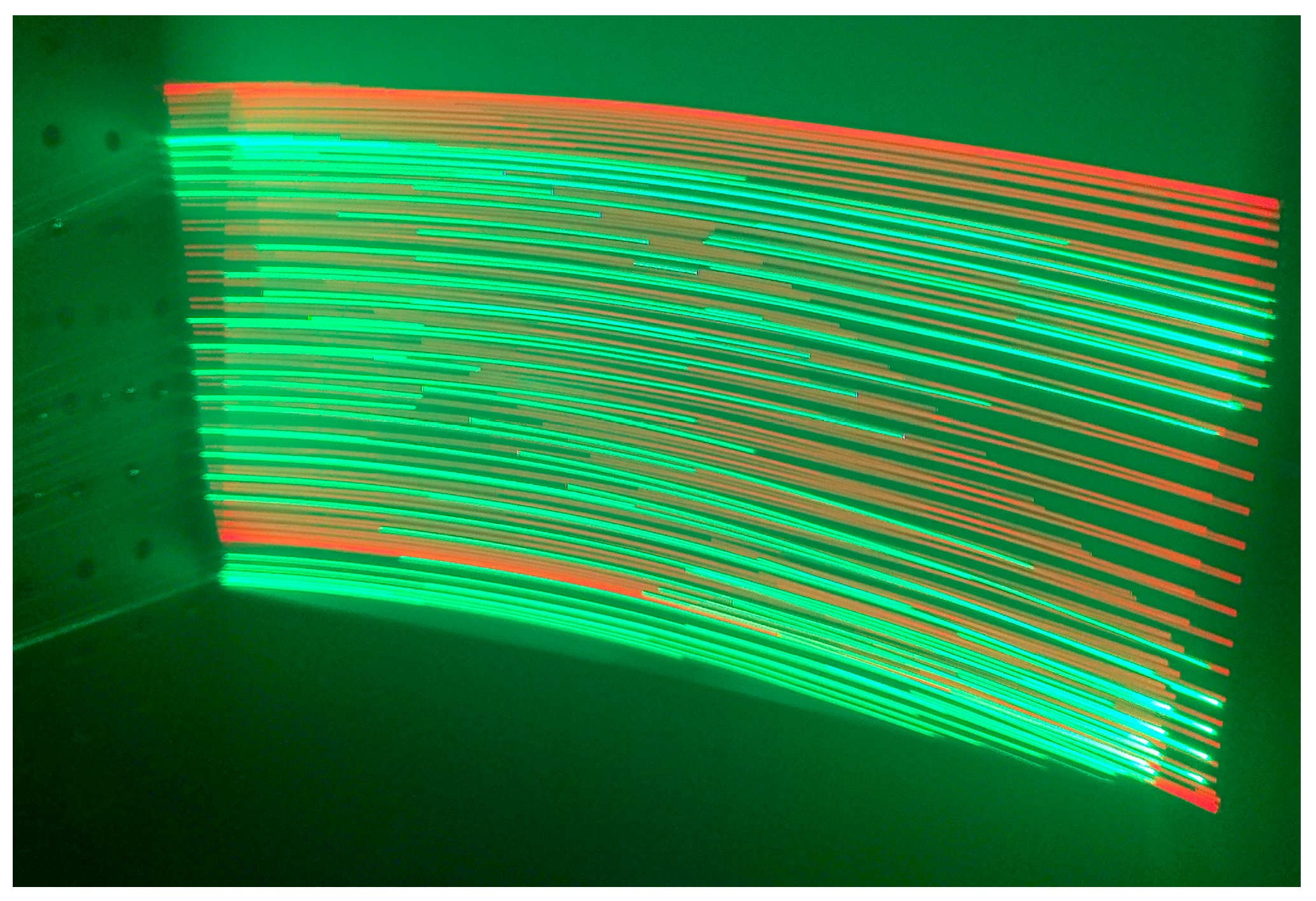
To verify the correctness of our design, we fabricated a simplified Fresnel prism and paired it with red and green lasers. The laser beams were deflected by the prism onto the MEMS micromirror, where they were reflected and scanned. The experimental schematic is shown in
Figure 13, and the scanning results are shown in
Figure 14. The figure shows that the red and green laser beams achieve alternating scanning, resulting in a higher spatial resolution for the system.
Figure 15 illustrates a three-dimensional model of the array reflector group and the Fresnel lens.
5. Conclusions
Lidar has been widely used in various applications, such as autonomous driving, robot navigation, and drone obstacle avoidance, due to its advantages of a high resolution, high-ranging accuracy, and strong anti-interference ability. The MEMS lidar technology route has been widely adopted due to its miniaturization and solid-state nature.
To address the small scanning angles in MEMS micromirrors and the limitations of the current supporting optical system, which cannot optimize both the scanning angle and spatial resolution simultaneously, this study proposes a MEMS lidar-transmitting optical system that uses a group of reflectors and a Fresnel lens to achieve wide scanning angles and high spatial resolution.
The array reflector group is used to convert the sparse array laser beam into a compact array laser beam, overcoming the gap between the beams caused by the mechanical structure. This study analyzed the relationship between the laser beam divergence angle and spatial resolution, determined the scanning scheme with the highest beam space-filling ratio, and achieved the highest system detection efficiency. Here, we designed a Fresnel lens and used a single MEMS micromirror to achieve the large-angle scanning of the array laser beam. While ensuring high spatial resolution, the system achieves large-angle scanning of the target area. The scanning range is 120° × 60°, the spatial resolution is 0.05° × 0.25°, and the beam-filling ratio reaches 90.63%.
