Article

Research on the Initial Orientation Technology of the View Axis for Underwater Laser Communication Dynamic Platforms Based on Coordinate Transformation Matrix Positioning Model

1
School of Optoelectronic Engineering, Changchun University of Science and Technology, Changchun 130022, China
2
National and Local Joint Engineering Research Center of Space Optoelectronics Technology, Changchun University of Science and Technology, Changchun 130022, China
*
Author to whom correspondence should be addressed.
Photonics 2025, 12(9), 839; https://doi.org/10.3390/photonics12090839
Submission received: 25 July 2025 / Revised: 13 August 2025 / Accepted: 21 August 2025 / Published: 22 August 2025

Abstract

To address the challenge of directly applying space laser communication systems to dynamic underwater environments, this paper integrates coordinate transformation matrices with underwater positioning systems, proposing an ultra-short baseline (USBL) system combined with a coordinate transformation-based underwater positioning model. The model is designed to effectively compensate for underwater dynamic disturbances, enhance the pointing accuracy of the system, and achieve stable tracking between underwater platforms. Simulation results demonstrate that the proposed model can enhance system tracking accuracy to 130.31 μrad (an improvement of 32.24%). Through underwater experiments, the results demonstrate that the underwater positioning model enables the system to achieve a pointing accuracy of 2.82 mrad (an improvement of 39.87%) and a tracking accuracy of 181.70 μrad (an improvement of 31.46%). Additionally, it can achieve underwater communication at 50 m with a data rate of 10 Mbps, providing a reference for future research on dynamic underwater laser communication.

1. Introduction

Currently, the majority of underwater communication relies on acoustic waves and radio waves to transmit information. However, acoustic waves have a short transmission distance, slow speed, and are susceptible to eavesdropping when used underwater [1,2,3]. On the other hand, radio waves experience significant attenuation underwater, resulting in limited transmission distances. Laser communication has the advantages of high transmission capacity and high spectral efficiency, and has now become a hotspot in research. Underwater laser communication has advantages such as large bandwidth, high frequency, high capacity, low latency, and high security, compared to traditional underwater acoustic communication and underwater electromagnetic wave communication [4], as shown in Table 1.
Similar to space laser communication, the establishment of underwater laser communication links generally employs beacon light capture. When the system initiates communication, it first uses a beacon light for alignment. After aligning the transmitter and receiver, it then switches to a signal light for communication. However, due to the disturbances caused by underwater turbulence, there exists relative motion and attitude shaking between platforms, which leads to uncertainties in the direction of the communication transmission source. This significantly increases the difficulty of establishing communication links and greatly reduces the reliability of the system [5]. Therefore, minimizing alignment deviations, improving pointing accuracy, and reducing the difficulty of optical path alignment have become key research focuses in underwater laser communication.
Current research on traditional underwater laser communication systems aims to reduce alignment difficulty by increasing the divergence angle of the light source through the use of LED multi-source arrays to reduce absorption losses in seawater [6]. However, due to the increase in divergence angle, there is a significant loss of free space, making it difficult to apply to long-distance underwater laser communication systems. Therefore, current research primarily focuses on applying spatial acquisition, pointing, and tracking (APT) systems in underwater environments, utilizing laser diode (LD) sources with better directional collimation to address the issue of optical path alignment [7]. In 2018, Solanki P.B. et al. proposed a novel alignment method based on the Extended Kalman Filter, which enables laser link alignment at a distance of 3 m with an angle of 60°, achieving a communication performance with a packet loss rate of 9.9% [8]. In 2019, Anirban Bhowal et al. proposed a novel unidirectional relay system for free-space optical communication, where the signal-to-noise ratio (SNR) of the Transmitter Laser Selection (TLS) system is improved by at least 10 dBm compared to traditional free-space optical (FSO) communication systems [9]. In 2020, the University of Strathclyde in the UK developed an UWOC system based on a 450 nm micro-LED array, achieving a communication distance of 4.5 m with a data rate of 3.4 Gbps and a bit error rate of 3.1 × 10⁻³ [10]. In the same year, Liu Hao et al. proposed an EKF-based underwater LD communication precise alignment control algorithm, which achieved a receiver alignment error of less than 2 mm when the transmission distance was less than 25 m [11]. In 2021, Palitharathna Kapila W. S. et al. studied a collaborative non-orthogonal multiple access (NOMA) assisted underwater laser communication system, which significantly improves communication rates compared to traditional access methods using multi-antenna systems [12]. In 2022, Wang Zhiqiang et al. developed an underwater laser communication system with APT capabilities, which can accurately track targets within a range of 10 m, achieving an alignment precision of 5 mrad [13]. In 2024, Aravind J. V. et al. proposed the deployment of an experimental device equipped with a single-beam sonar for node localization. Through simulations, they achieved a communication rate of 1 Gbps at a distance of 3.13 m [14].
This paper investigates the alignment and tracking issues between platforms in underwater dynamic environments. Firstly, the basic principles of underwater laser communication are introduced, and the workflow of initial optical axis pointing is briefly analyzed. Based on the random wave theory, this paper analyzes the external disturbances affecting the system and establishes an equivalent disturbance model. Subsequently, the ultra-short baseline (USBL) underwater positioning system is introduced, and a USBL system combined with coordinate system transformation suitable for platform-to-platform positioning in underwater dynamic environments is constructed. Through simulation, the model’s effectiveness in improving system tracking accuracy is verified. Finally, an experimental platform is set up, demonstrating that the USBL system combined with coordinate system transformation can enhance the pointing and tracking accuracy of underwater laser systems and achieve communication functionality.

2. Control Principles of Underwater Laser Communication Systems

2.1. Principle of Underwater Laser Communication System

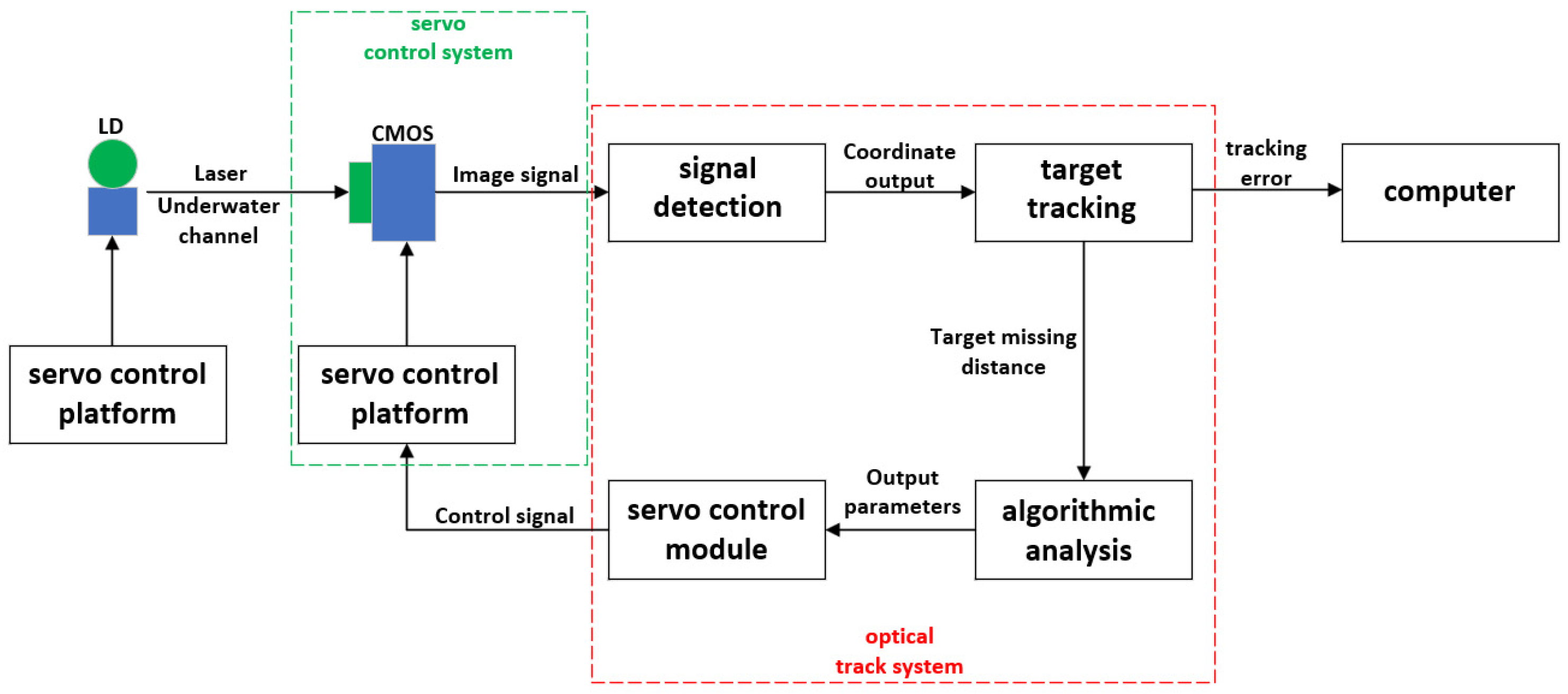
Underwater laser communication is a communication method that uses laser beams as the propagation signal. Its link primarily consists of the transmitter module, receiver module, optoelectronic tracking system, servo control platform, and upper computer [15]. The system block diagram is shown in Figure 1. The transmitter uses a laser diode (LD) as the light source, which features a small divergence angle and high bandwidth, allowing for concentrated light intensity that enables long-distance and high-speed data transmission. The servo control platform employs a two-dimensional servo turntable to adjust the horizontal and pitch angles. The CMOS camera at the receiver captures image signals and transmits them to the optoelectronic tracking system, achieving the system’s coarse tracking function. The optoelectronic tracking system is responsible for processing the spot information and outputting control signals to drive the servo control platform, thereby ensuring the stable operation of the communication link.
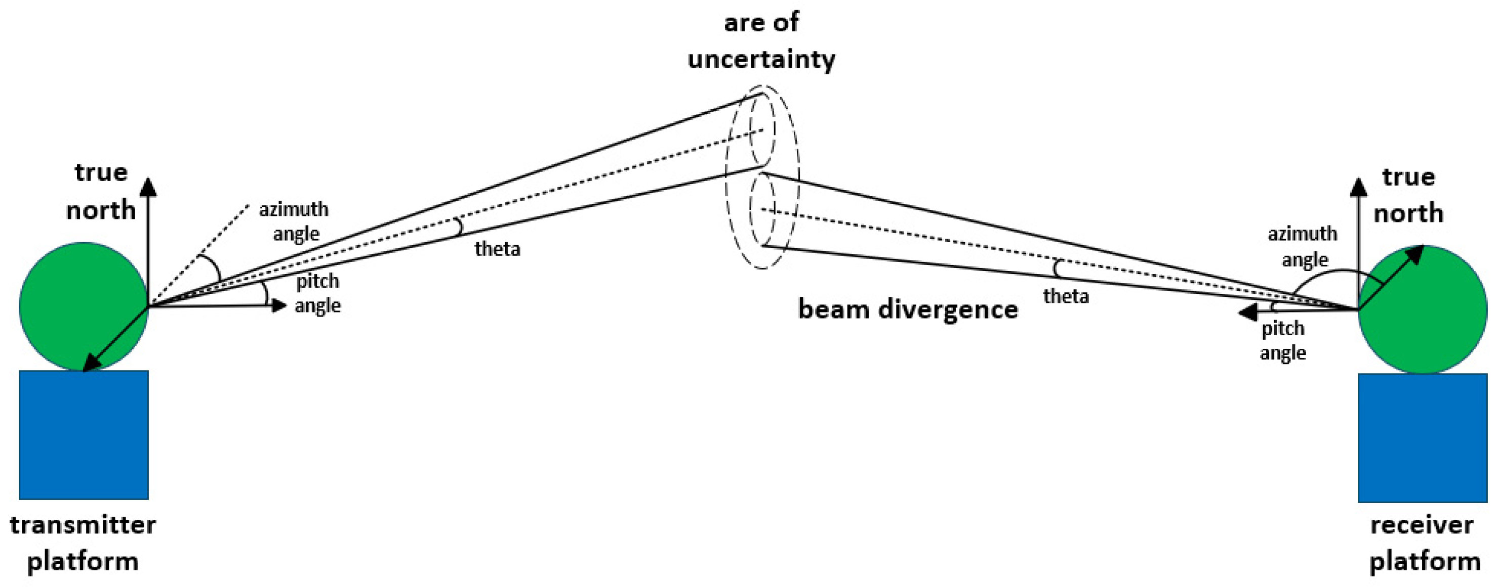
The APT subsystem is a crucial component of laser communication systems, with the initial alignment of the optical axis being the first step in the operation of the APT system. This step holds significant research value within laser communication systems [16]. The workflow for the initial alignment of the optical axis involves rotating the communication optical axis from its zero position to point towards the uncertain area of the communication counterpart, as illustrated in Figure 2. The principle is based on the premise of knowing the absolute positions and real-time attitude angles of both the underwater transmitting and receiving platforms, and achieving high-precision time synchronization between them. By employing coordinate transformation methods, the azimuth and elevation angles for the mutual pointing of the platforms’ optical axes are calculated. The electro-optical tracking system outputs the angle information to the control module, which drives the servo control platform to rotate the optical axis from its initial zero position, achieving precise pointing towards the counterpart. The key to performing the coordinate transformation calculation is obtaining high-precision platform position parameters and attitude data parameters.

2.2. Servo System Model Analysis

The underwater laser communication servo control system employs a direct current torque motor as the actuator, forming a typical electromechanical motion servo control system. The motor drive model of this system is illustrated in Figure 3.
According to Figure 3, the electromotive force balance equation of the motor and the dynamic equations between the motor and the load are as follows:
u a = u c + I i R i + L i d I i d t
u c = K e v
J 1 d v d t = M 0 M 1
J 2 d v d t = M 2 M L
M 0 = K i I i
where ua represents the armature winding voltage, uc denotes the armature back electromotive force, Ii signifies the armature winding current, Ri stands for the armature winding resistance, Li indicates the armature winding inductance, Ke is the back electromotive force constant, v is the angular velocity of both the motor shaft and the load shaft, J1 is the motor moment of inertia, J2 is the load moment of inertia, M0 is the motor output torque, M1 is the motor shaft resistance torque, M2 is the load shaft driving torque, ML is the load shaft disturbance torque, and Ki is the motor torque coefficient.
In the process of system modeling, the motor and the load can be considered as an integrated entity, sharing the same velocity v. Therefore, M1 = M2, and from Equations (3) and (4), we obtain the following:
J d v d t = M 0 M L
where J = J1 + J2. By performing the Laplace transform on Equation (6), the structure of the motor and load model can be derived as shown in Figure 4.
The transfer function of the motor and its load, calculated using Mason’s formula, is as follows:
G ( s ) = v ( s ) u a ( s ) = 1 / C e ( T e s + 1 ) ( T m s + 1 )
where T m = J R i K b K i is the mechanical time constant, and T e = L i / R i is the electrical time constant.
Through the analysis of the principles of underwater laser communication systems and the servo system model, a simulation platform can be established to verify the rationality of the underwater positioning model combining the USBL system with coordinate system transformation, as described below.

2.3. Analysis of Underwater Disturbance

Underwater disturbances are the primary cause of changes in the attitude of underwater platforms. Water disturbances are typically modeled as stationary random processes. These disturbances are assumed to comprise long-crested random sea waves. This paper simulates and analyzes such sea waves to investigate the attitude changes they induce during underwater platform tracking operations.
Random sea waves are typically regarded as a stationary Gaussian random process. According to linear wave theory, the sea surface can be viewed as a linear superposition of numerous harmonic waves with varying frequencies, different random initial phases, and amplitudes determined by the specified wave spectrum S(ω) [17]. The wave height can be expressed as follows:
η ( t ) = a i cos ( ω i t + ε i )
where ai represents the amplitude of the i-th harmonic wave, ωi denotes the frequency of the random sea wave, and i is the initial phase.
This paper modifies the Pierson–Moskowitz (P–M) spectrum by replacing the mean wind speed parameter with the significant wave height, for the analysis of random sea waves [18]. The ITTC single-parameter wave spectrum can be expressed as follows:
S ω w = A ω w 5 exp B ω w 4
where A = 8.1 × 10⁻³g2, B = 3.11 h 1 / 3 2 , h1/3 represents the significant wave height, g = 9.81 m/s2 is the acceleration due to gravity, and ω is the frequency of random sea waves, measured in rad/s.
By discretizing the frequency bands where wave spectrum energy is concentrated and superimposing harmonic components, the amplitude of the ii-th harmonic wave is given as follows:
a i = 2 S ( ω ) Δ ω
where Δω is the frequency step, and S(ωi) is the wave spectral density at ωi.
Considering the underwater platform as being mounted on the SUBOFF submarine model [19] developed by the United States Defense Research Institute, the simplified model of the platform under disturbance can be expressed as follows:
α ( t ) = arctan a i cos ( ω i t + ε i ) l
where l is the length of the SUBOFF submarine model, which is 105.4 m.
When the random wave conditions are set to Sea State 3, the significant wave height (h1/3) is 0.9 m, the wave spectrum S(ω) is defined over the frequency range ω ∈ [0.5, 5] rad/s, and the peak wave period is at 6.43 s. The platform attitude disturbance is represented by Equation (9). Based on the above conditions, establish an underwater platform attitude disturbance model, and obtain the equivalent seawater disturbance waveform as shown in Figure 5.
By analyzing the disturbances in seawater, an equivalent disturbance model for seawater has been established. In the subsequent sections, this model will be integrated as a disturbance input into the simulation module for subsequent experimental validation.

3. Modeling of Initial Orientation of Visual Axis

3.1. Principle of USBL System
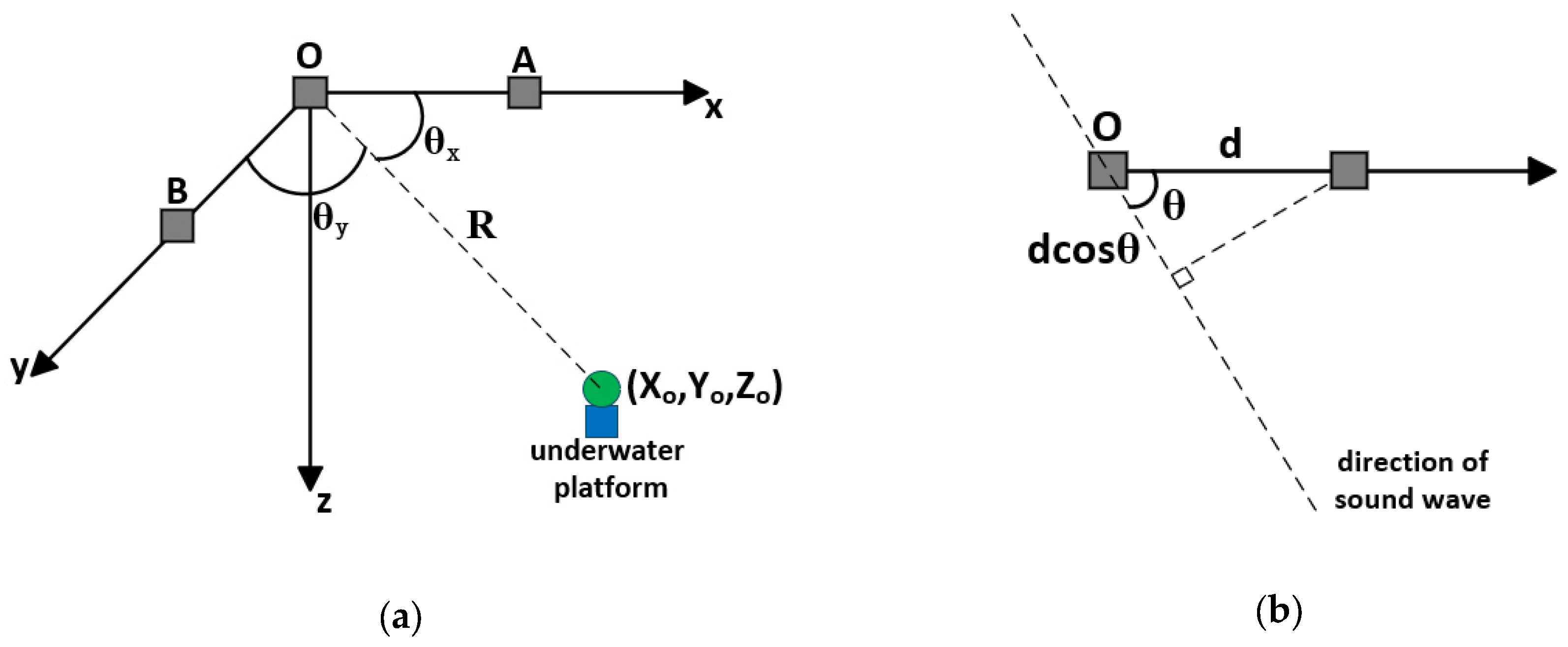
The initial pointing system undergoes a series of coordinate transformations to ultimately provide the azimuth and pitch angles required for rotation relative to its initial zero position. During this process, the effects of installation angle errors, initial zero position errors, and changes in the platform’s location and attitude must be compensated for in real-time using a coordinate transformation matrix. It is essential to clarify the number of coordinate systems, the arrangement order among these systems, and the conventions for the positive and negative rotation angles, ensuring that all coordinate systems adhere to a unified standard, either left-handed or right-handed [20].
Unlike terrestrial positioning, underwater positioning technology requires signals to have the ability to penetrate the water medium. Therefore, this paper needs to integrate a super-short baseline underwater positioning system that uses sonar as the propagation signal to obtain the coordinates of the underwater platform. The super short baseline underwater positioning system boasts advantages such as simple installation, ease of operation, no need to establish an underwater baseline array, and high ranging accuracy [21].
Where A, B, and O represent the acoustic array, while θx and θy denote the angles between the origin O of the array and the sound wave propagation trajectory with respect to the x-axis and y-axis, respectively.
However, the ultra-short baseline system has an acoustic array size that is too small to calculate the time taken for signals emitted from the underwater platform to reach the array. Therefore, it is necessary to utilize the phase difference to obtain the orientation of the underwater platform for positioning purposes. Let the signal frequency be f; then, the wavelength λ is given by v/f, where d is the spacing between the acoustic array elements (such as element A and O, element B and O). As shown in Figure 6, the phase difference can be expressed as follows:
ϕ = 2 π d λ cos ( θ )
The incident angles of the signal, θx and θy, can be expressed as follows:
θ x = arccos λ ϕ x 2 π d θ y = arccos λ ϕ y 2 π d
The distance R from the underwater platform to the origin of the acoustic array can be measured by sonar, represented as follows:
R = v t
Therefore, the coordinates (Xo, Yo, Zo) of the underwater platform at the origin of the array can be represented as follows:
X o = R cos θ x Y o = R cos θ y Z o = R 1 cos 2 θ x cos 2 θ y
Figure 6. (a) Schematic diagram of USBL system. (b) Schematic diagram of phase difference calculation for USBL.
Photonics 12 00839 g006

3.2. Coordinate Systems Involved in the Transformation Process

The initial pointing modeling is achieved through a series of coordinate transformation processes, ultimately determining the azimuth and elevation angles required for the line of sight relative to its initial zero position. This process must compensate in real-time for the effects of platform position and attitude changes on the pointing system, as well as for differences in system installation angles and initial zero position discrepancies. All the aforementioned compensations are implemented through coordinate transformation matrices. When applying the coordinate transformation matrices, it is essential to clarify the number of coordinate systems, the sequence of these coordinate systems, and the sign conventions for the rotation angles. Furthermore, all coordinate systems should adhere to the same standard, either all being left-handed or right-handed.
WGS-84 Coordinate System: The origin of the coordinate system is the center of the Earth, with the Z-axis pointing towards the direction of the geodetic pole (CTP) as defined by BIH (1984.0). The X-axis points towards the intersection of the zero-degree meridian defined by BIH and the CTP equator, while the Y-axis, along with the Z and X axes, forms a right-handed coordinate system.
The North-East-Up (NEU) coordinate system: The origin of the coordinates is usually the origin of the test coordinate system, with the Y-axis pointing towards true geographic north (North), the X-axis oriented towards the east in the direction of the Earth’s rotation, and the Z-axis pointing vertically upwards (Up), forming a right-handed coordinate system.
Measurement Coordinate System: Determined by the attitude testing instrument used, the origin is set at the center of the instrument. The X-axis extends to the right along the horizontal axis of the testing instrument, the Y-axis extends forward along the vertical axis of the testing instrument, and the Z-axis is perpendicular to both the X-axis and Y-axis, following the right-hand rule.
Platform Coordinate System: The origin is located at the center of the base platform. The X-axis extends to the right along the horizontal axis of the base platform, the Y-axis extends forward along the vertical axis of the base platform, and the Z-axis is perpendicular to both the X-axis and Y-axis, following the right-hand rule.
Viewing Axis Coordinate System: The origin is located at the center of the optical antenna. The X-axis extends to the right along the horizontal axis of the base, the Y-axis represents the viewing axis direction, and the Z-axis forms a pair of orthogonal axes with the X and Y axes, following the right-hand rule.

3.3. Coordinate Transformation Order and Transformation Matrix

The final rotation angle of the viewing axis is defined in the viewing axis coordinate system, and its rotation angle can be expressed as follows:
α r = 180 ° × arctan ( X u / Y u ) / π β r = 180 ° × arctan ( Z u / X u 2 + Y u 2 ) / π
where α r and β r represent the azimuth and elevation angles of the turntable, respectively. The coordinates (Xu, Yu, Zu) denote the coordinates of the opposite turntable in the visual axis coordinate system of our own turntable. Therefore, coordinate transformation is necessary to obtain the coordinates, as illustrated in Figure 7.
  • The transformation of the WGS-84 coordinate system into the geocentric coordinate system involves converting latitude, longitude, and elevation values into rectangular coordinate values. The ellipsoidal parameters are selected according to the WGS-84 ellipsoid model. The transformation formulas can be expressed as follows:
X o Y o Z o = ( N + H ) cos B cos L ( N + H ) cos B sin L [ N ( 1 e 2 ) + H ] sin B
where N = a 1 e 2 ( sin B ) 2 , a = 6,378,137 m represents the semi-major axis, and e2 = 0.006694379995 denotes the square of the first eccentricity of the ellipsoid. B, L, and H correspond to the longitude, latitude, and elevation value of the acoustic array center, respectively. The geocentric coordinates of the acoustic array are denoted by (Xo, Yo, Zo).
In combination with Equation (15), the geocentric coordinates of the underwater turntable (Xr, Yr, Zr) can be expressed as follows:
X r = X o + R cos θ x Y r = Y o + R cos θ y Z r = Z o + R 1 cos 2 θ x cos 2 θ y
2.
The transformation matrix from the WGS-84 coordinate system to the NEU coordinate system: Since the dynamic line-of-sight alignment is performed between platforms, the pointing system needs to compensate in real-time based on the changes in platform position. Converting the WGS-84 coordinate system to the North-East-Up coordinate system enables this compensation function. The transformation matrix C e n can be expressed as follows:
C e n = sin L cos L 0 sin B cos L sin B sin L cos B cos B cos L cos B sin L sin B
where B’ and L’ represent the longitude and latitude of the origin in the NEU coordinate system, which can be obtained from Equations (17) and (18), and are expressed as follows:
B = arctan [ Z r ( N + H ) X r 2 + Y r 2 ( N ( 1 e 2 ) + H ) ] L = arctan Y r X r
3.
The transformation matrix from the NEU coordinate system to the measurement coordinate system: The platform’s dynamic pointing not only involves positional changes but also entails variations in orientation. The azimuth, pitch, and roll angles of the platform are subject to real-time changes, necessitating compensation by the pointing system. The transformation matrix from the NEU coordinate system to the test coordinate system can achieve this compensation functionality and the transformation matrix C n b can be expressed as follows:
C n b = cos φ cos ϕ sin φ sin θ sin ϕ cos φ sin ϕ + sin φ sin θ cos ϕ sin φ cos θ cos θ sin ϕ cos θ cos ϕ sin θ sin φ cos ϕ + cos φ sin θ sin ϕ sin φ sin ϕ cos φ sin θ cos ϕ cos θ cos φ
where ϕ , θ , φ represent the current azimuth, pitch, and roll angles of the platform, respectively.
4.
The transformation matrix from the measurement coordinate system to the platform coordinate system: Ideally, the test coordinate system should coincide with the base coordinate system; however, in practical applications, various factors such as machining and assembly precision limitations can lead to relative rotational deviations between the two coordinate systems. It is necessary to measure the relative offset angles between the three coordinate axes and compensate for them using a coordinate transformation matrix C b a , which can be expressed as follows:
C b a = cos θ x cos θ y sin θ x sin θ z sin θ y cos θ x sin θ y + sin θ x sin θ z cos θ y sin θ x cos θ z cos θ z sin θ y cos θ z cos θ y sin θ z sin θ x cos θ y + cos θ x sin θ z sin θ y sin θ x sin θ y cos θ x sin θ z cos θ y cos θ z cos θ x
where θ x, θ y, and θ z represent the angles between the x, y, and z axes of the two coordinate systems, respectively.
5.
The transformation matrix from the platform coordinate system to the viewing axis coordinate system: When the zero position of the visual axis does not coincide with the zero position of the base platform, there exist angles δy and δz between the y-axis and z-axis of the two coordinate systems. Since the underwater turntable’s visual axis only undergoes rotation in azimuth and pitch, there is no angle between the x-axis of the platform coordinate system and the visual axis coordinate system. Transforming the platform coordinate system to the visual axis coordinate system can achieve compensation functionality, and the transformation matrix C a r can be expressed as follows:
C a r = cos δ y sin δ y 0 cos δ z sin δ y cos δ z cos δ y sin δ z sin δ z sin δ y sin δ z cos δ y cos δ z
After the aforementioned coordinate transformation, the coordinates of the opposing turntable in the viewing axis coordinate system of our turntable can be obtained as (Xu, Yu, Zu). The calculation of the coordinate transformation matrix can be expressed as follows:
X u Y u Z u = C a r C b a C n b C e n X r X r Y r Y r Z r Z r
where (Xr, Yr, Zr) represent the geocentric coordinates of the opposing turntable, and (Xr, Yr, Zr) represent the geocentric coordinates of our own turntable.
From Equation (24), it can be deduced that by substituting the latitude, longitude, and elevation values of both the opposing and our turntables into Equation (18), the geocentric coordinates for both turntables can be obtained. Subsequently, substituting these geocentric coordinates into Equation (16) allows for the calculation of the initial orientation angle of the turntable.

3.4. Simulation Verification

Based on the USBL system combined with the coordinate transformation proposed in this paper, a simulation system for underwater laser link is established. The geocentric coordinates of both turntables collected from the experimental site serve as input data. During the simulation process, dynamic environmental disturbances are introduced to both turntables, generating the coordinates of the receiving end turntable in the coordinate system of the transmission end turntable’s visual axis at different moments, as illustrated in Figure 8.
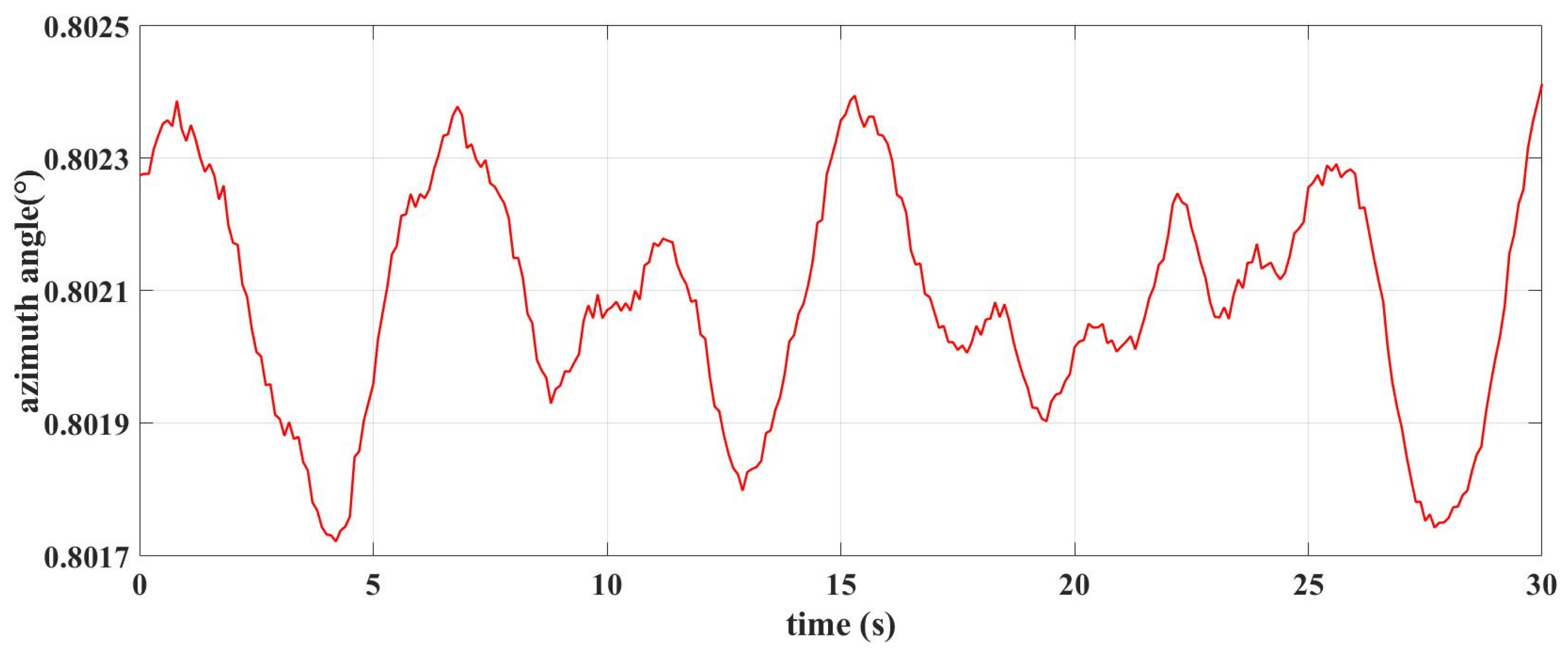
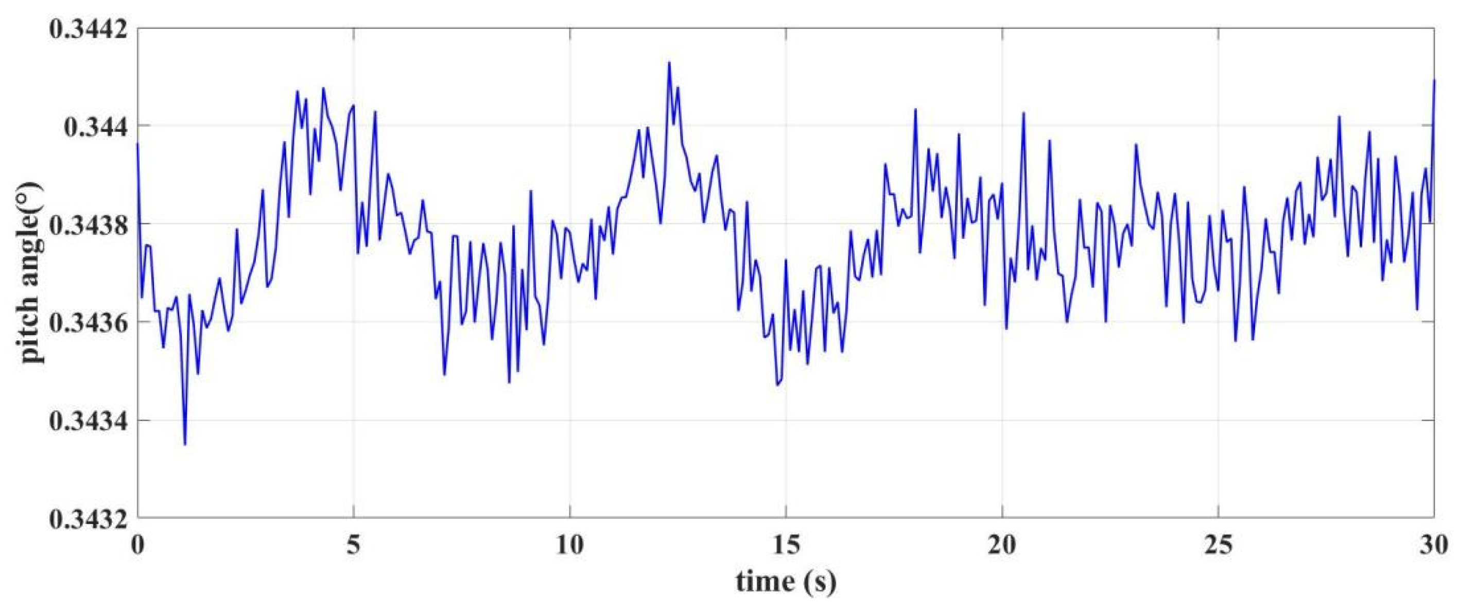
The incorporation of the coordinates of the receiving end turntable in the coordinate system of the transmission end turntable’s line of sight into the initial pointing system, simulating the initial pointing angles of the receiving end turntable at different moments in an underwater dynamic environment, is shown in Figure 9 and Figure 10.
To verify the control effectiveness of the underwater positioning model proposed in this paper on the underwater turntable, the Proportional–Integral–Derivative (PID) control algorithm and the PID control algorithm combined with the USBL system and coordinate system transformation-based underwater positioning model were, respectively, employed to achieve closed-loop control of the underwater platform. The specific process is illustrated in Figure 11.
The control system employs a dual closed-loop composite control strategy based on position and velocity, as illustrated in Figure 12. In the position loop, the difference between the target spot position and the output spot position is calculated, and this difference is processed by the position loop controller to provide input to the velocity loop. In the velocity loop, the input from the velocity loop is compared with the feedback value from the velocity loop, and this difference is processed by the velocity loop controller to drive the actuator. The actuator, guided by the control signal, drives the turntable to achieve disturbance compensation.
Where Gl(s) is the transfer function of the position loop controller, Gv(s) is the transfer function of the velocity loop controller, and G(s) is the transfer function of the system actuator. The coordinates of Figure 9 and Figure 10 are input as the initial positions into the system, and model fitting and identification are performed using MATLAB2021b’s System Identification Toolbox. The transfer function can be expressed as follows:
G l s = s 1 + 0.000625 s
G v s = 0.9 1 + 0.00398 s
G ( s ) = 7.916 1 + 1.4265 s
The PID control algorithm and the integration of the PID algorithm with the underwater positioning model were simulated in Simulink for step response analysis. Based on the real underwater environment, the input step signal was set to 1°. The output responses of the two systems were compared, and the results are shown in Figure 13.
By comparison, it can be observed that the output response time to reach steady state for the PID control algorithm is 1.1 s, with an overshoot of 5%. In contrast, the output response time when incorporating the underwater positioning model PID algorithm proposed in this paper reaches steady state in 0.6 s, with an overshoot of 1%. Simulation results indicate that the integration of the underwater positioning model PID algorithm can reduce the system response time by 45.5% and decrease the overshoot by 80%. Therefore, the underwater positioning model, combined with the PID control algorithm, can significantly enhance the dynamic control performance of the system.
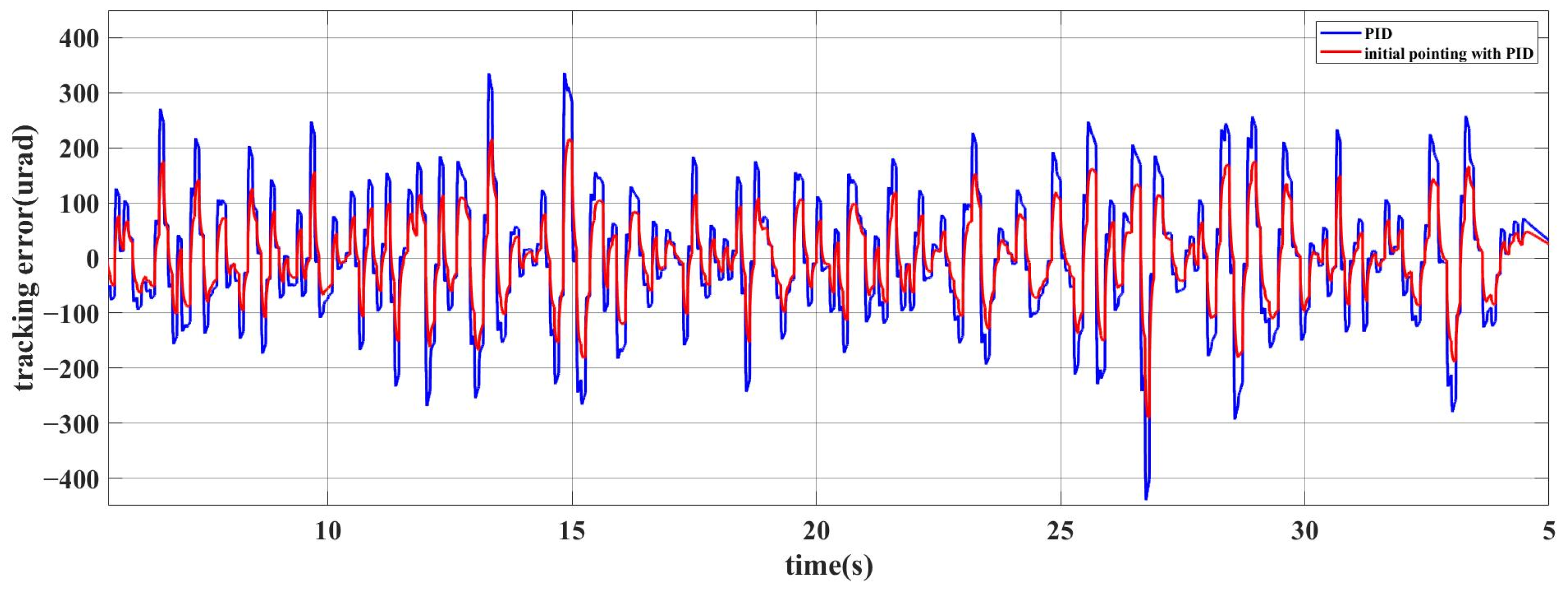
The initial pointing angle of the turntable obtained is incorporated as the attitude input parameter into the tracking link simulation system, simulating the initial pointing of the link. During the simulation process, the aforementioned equivalent seawater interference is added to the disturbance module, and a comparison is made with the underwater positioning model not used in this paper, resulting in the tracking accuracy errors shown in Figure 14.
Comparative analysis reveals a significant reduction in the tracking error of the visual axis when employing the USBL system with coordinate transformation model. Specifically, the peak tracking error of the visual axis without the USBL system with coordinate transformation model is 420.26 µrad, with a root mean square (RMS) of 192.3 µrad. In contrast, after implementing the USBL system with coordinate transformation model, the peak tracking error of the visual axis is reduced to 297.5 µrad, and the RMS is 130.31 µrad. Simulation results indicate that the USBL system with coordinate transformation model can enhance system tracking accuracy by 32.24%; therefore, the improvement effect is significant.

4. Experimental Verification

To validate the practical effectiveness of the ultra-short baseline system combined with the coordinate transformation underwater positioning model proposed in this paper, an underwater laser communication platform was constructed as shown in Figure 15.
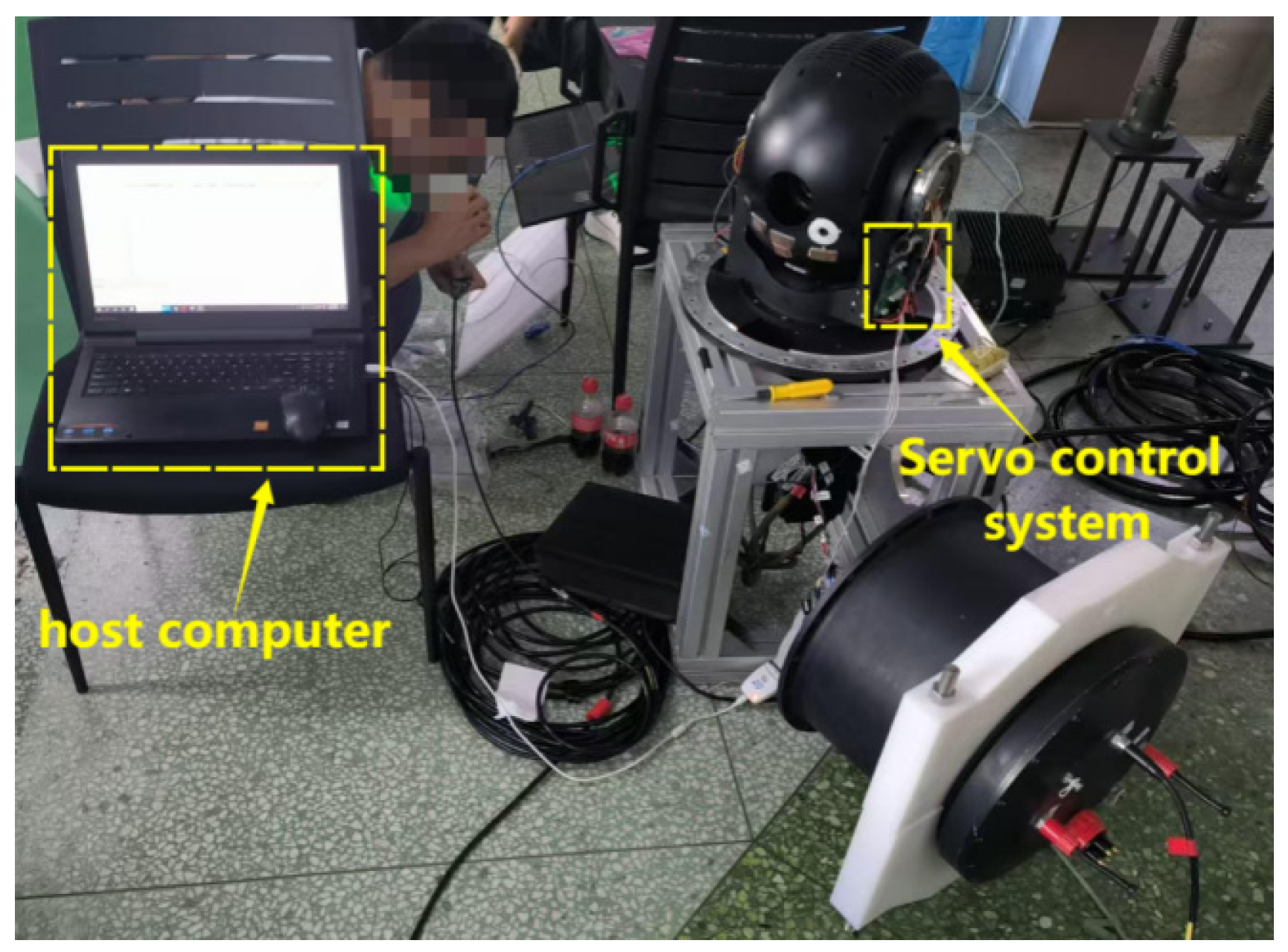
As shown in Figure 16, the STM32F407 chip is employed as the core of the servo control system. The motor controls the azimuth and pitch movements of the turntable, forming a servo control platform that enables dynamic pointing between underwater platforms. The target tracking module transmits tracking errors to the upper computer in real-time at a transmission frequency of 200 Hz, while the servo control system also processes the tracking errors to control the motor’s rotation. This experiment utilizes a laboratory water tank measuring 50 m in length and 1.5 m in width as the experimental site for underwater dynamic platform tracking, as shown in Figure 17.
After the system is set up, both platforms need to undergo coaxial calibration. A blue light with a wavelength of 465 nm is used as the beacon light, with the divergence angle set to 35 mrad. When the spot of the beacon light is positioned at the center of the other party’s camera, the two platforms can be considered to be on the same axis, as shown in Figure 18.
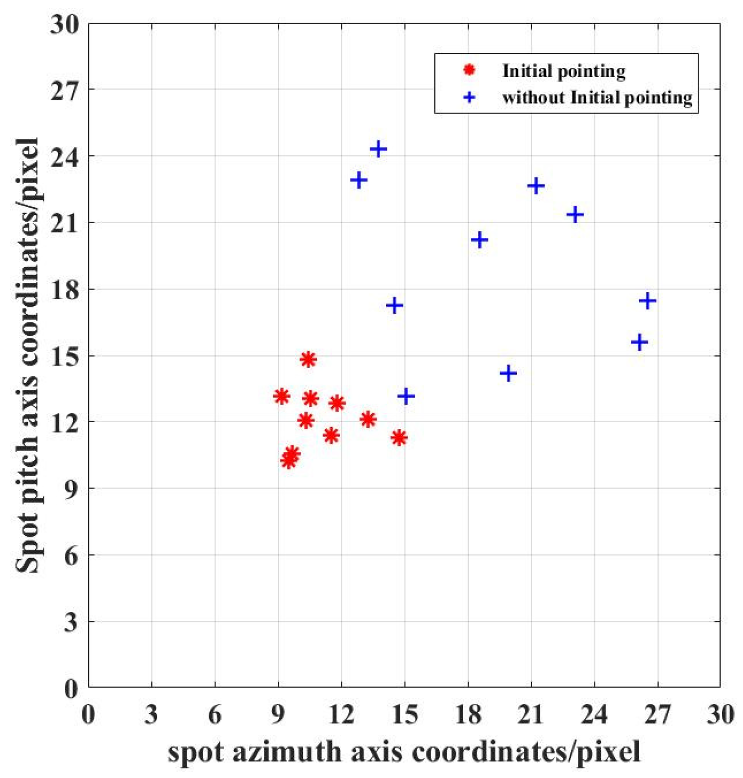
Based on the results of the underwater disturbance analysis, the equivalent disturbance can be regarded as a sinusoidal signal with an amplitude of 0.13° and a frequency of 0.1 Hz. The coordinates of the opposing turntable are adjusted to (70, 5000, 30) in the coordinate system of our turntable’s optical axis. An equivalent disturbance is applied to the underwater platform’s photoelectric tracking module to replace the actual wave interference. To verify the stability and accuracy of the USBL system with coordinate transformation model, repeated multiple initial directional comparative experiments are conducted. The positions of the signal light spot center on the imaging camera are recorded, as shown in Figure 19.
The points in the figure represent the distribution of light spots on the camera’s target surface. The blue coordinate points indicate the positions of light spots when the underwater positioning model is not used, while the red coordinate points represent the positions when the underwater positioning model is employed. It can be observed from the figure that the distribution of light spots using the USBL system with coordinate transformation model is more concentrated, with a significant reduction in offset. In the experiment, the camera’s single-pixel resolution was observed to be 170 urad. The RMS calculation of the initial pointing error of the light spot showed that the initial pointing accuracy was 4.69 mrad without the underwater positioning technology and improved to 2.82 mrad with the underwater positioning technology, resulting in an average improvement of 39.87% in the initial pointing accuracy of the visual axis.
The image tracking the light spot to the center of the camera is shown in Figure 20, where both platforms can complete alignment within 2.5 s.
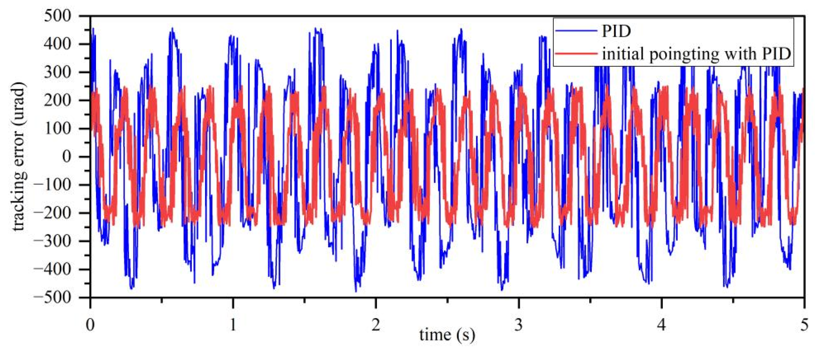
The servo control system transmits tracking errors to the upper computer at a frequency of 200 Hz. The upper computer processes the data to compute the RMS values, recording the tracking errors for both the traditional PID algorithm control and the USBL system with coordinate transformation model with PID algorithm control. The system’s tracking errors are illustrated in Figure 21 and Figure 22. The peak azimuth tracking error for the traditional PID algorithm control is 461.41 μrad, with an RMS value of 284.68 μrad; the peak pitch tracking error is 364.74 μrad, with an RMS value of 245.52 μrad; and the overall tracking accuracy is 265.10 μrad. In contrast, the peak azimuth tracking error for tthe USBL system with coordinate transformation model with PID algorithm control is 255.62 μrad, with an RMS value of 171.88 μrad; the peak pitch tracking error is 289.76 μrad, with an RMS value of 191.52 μrad; and the overall tracking accuracy is 181.71 μrad. The experimental results indicate that the USBL system with coordinate transformation model can improve the system’s tracking accuracy by 31.46%, which is closely aligned with the simulation results.
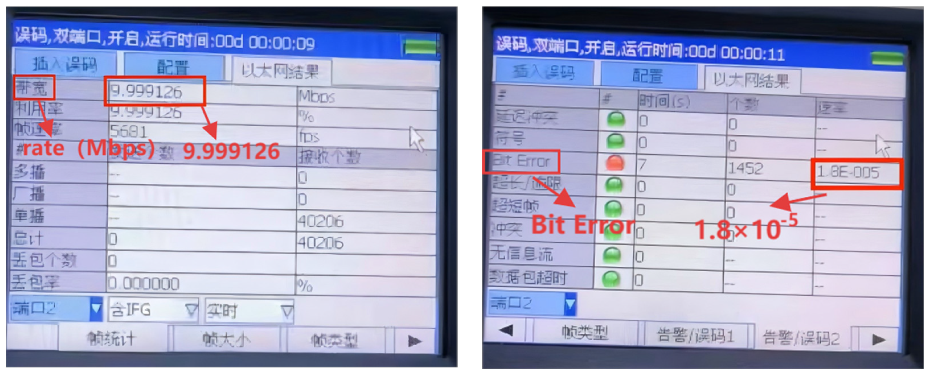
To validate the communication capabilities of the platform after completing tracking, underwater laser communication experiments were conducted in a laboratory pool. The transmitting signal from our platform was modulated using On-Off Keying (OOK) and data encoding. A performance analysis of the communication was carried out on the counterpart platform, with the experimental results shown in Figure 23. At a communication rate of 10 Mbps and a distance of 50 m, the system’s bit error rate (BER) was found to be 1.8. × 10−5

5. Conclusions and Discussion

Currently, research on underwater laser communication systems mainly focuses on preliminary alignment in static or quasi-static scenarios, lacking efficient, robust, and practical dynamic real-time tracking solutions for the dynamic disturbances commonly encountered in actual applications. This paper addresses the challenge of establishing the initial pointing direction for laser communication links in underwater dynamic environments by proposing an underwater positioning model that integrates USBL positioning with a coordinate transformation matrix. The model aims to enhance system pointing accuracy and tracking stability by real-time compensating for platform attitude disturbances and positional changes.
First, this study constructs an equivalent disturbance model for underwater platforms based on random wave theory, quantifying the attitude interference characteristics under three levels of sea conditions, thereby providing a basis for disturbance input in dynamic alignment control. Next, an underwater positioning model combining ultra-short baseline systems with coordinate transformation is established, achieving the precise calculation of absolute positions and relative attitudes between underwater platforms. Simulation results validate that this model can improve system tracking accuracy by 32.24%, achieving a tracking precision of 130.31 μrad. Finally, experimental validation shows that this model enhances system pointing accuracy by 39.87%, reaching 2.82 mrad, and improves tracking accuracy by 31.46%, reaching 181.70 μrad, successfully achieving communication over a distance of 50 m at a rate of 10 Mbps. The USBL system proposed in this paper integrates a coordinate transformation underwater positioning model, effectively addressing the challenge of initial pointing direction of the visual axis in underwater dynamic platform laser communication. This significantly enhances the pointing accuracy and tracking stability of the system while reducing the difficulty of establishing connections. It provides a certain reference for the research on point-to-point connection establishment in underwater dynamic platforms.
However, due to limitations in experimental conditions, the underwater laser communication system could not be tested on an unmanned underwater vehicle. In future research, we plan to conduct further experimental validation in real marine environments. Additionally, we will investigate underwater multi-antenna laser communication systems to address the potential issue of obstacles such as marine organisms temporarily blocking the link in actual sea conditions.

Author Contributions

Conceptualization, J.M. and Y.T.; methodology, J.M. and Y.L. (Yang Liu); software, J.M.; validation, M.Z. and C.Q.; formal analysis, H.Q.; investigation, J.M.; resources, Y.T. and Y.L. (Yang Liu); data curation, J.M.; writing—original draft preparation, J.M.; writing—review and editing, J.M.; visualization, Y.L. (Yanpu Li); supervision, Y.T. and Y.L. (Yang Liu); project administration, Y.T. and Y.L. (Yang Liu); funding acquisition, Y.T. and Y.L. (Yang Liu). All authors have read and agreed to the published version of the manuscript.

Funding

This work was financially supported by the Jilin Province Science and Technology Department, China (YDZJ202501ZYTS288).

Institutional Review Board Statement

Not applicable.

Informed Consent Statement

Not applicable.

Data Availability Statement

Data underlying the results presented in this paper are not publicly available at this time but may be obtained from the authors upon reasonable request.

Conflicts of Interest

The authors declare no conflicts of interest.

References

  1. Zhao, Y.; Wang, A.; Zhu, L.; Lv, W.; Xu, J.; Li, S.; Wang, J. Performance evaluation of underwater optical communications using spatial modes subjected to bubbles and obstructions. Opt. Lett. 2017, 42, 4699–4702. [Google Scholar] [CrossRef] [PubMed]
  2. Ebihara, T.; Leus, G.; Ogasawara, H. Underwater acoustic communication using Doppler-resilient orthogonal signal division multiplexing in a harbor environment. Phys. Commun. 2018, 27, 24–35. [Google Scholar] [CrossRef]
  3. Wang, J.; Lu, C.; Li, S.; Xu, Z. 100 m/500 Mbps underwater optical wireless communication using an NRZ-OOK modulated 520 nm laser diode. Opt. Express 2019, 27, 12171–12181. [Google Scholar] [CrossRef] [PubMed]
  4. Wu, T.-C.; Chi, Y.-C.; Wang, H.-Y.; Tsai, C.-T.; Lin, G.-R. Blue Laser Diode Enables Underwater Communication at 12.4 Gbps. Sci. Rep. 2017, 7, 40480. [Google Scholar] [CrossRef] [PubMed]
  5. Yang, Y.; Yan, Z.W.; Yao, X.Y. Analysis of the Impact of Pointing-Jitter Error on the Performance of Wireless Optical Communication Systems in Underwater Turbulent Channels. Acta Opt. Sin. 2024, 44, 1201005. [Google Scholar]
  6. Lv, Z.; Liu, X.; Wu, S.; Zhang, W.; Yue, C.P.; Liu, Z. Massive GaN micro-LED array based underwater wireless optical communication. Opt. Express 2025, 33, 19527–19534. [Google Scholar] [CrossRef] [PubMed]
  7. Wang, J.X. Research on Key Technologies of Dynamic Underwater Wireless Optical Communication Based on Servo Control. Master’s Thesis, Changchun University of Science and Technology, Changchun, China, 2024. [Google Scholar]
  8. Solanki, P.B.; Al-Rubaiai, M.K.; Tan, X. Extended Kalman filter-based active alignment control for LED optical communication. IEEE/ASME Trans. Mechatron. 2018, 23, 1501–1511. [Google Scholar] [CrossRef]
  9. Anirban, B.; Singh, R.K. Transmit Laser Selection for Two Hop Decode and Forward FSO Communication with Pointing Errors. IEEE Commun. Lett. 2019, 23, 2301–2305. [Google Scholar] [CrossRef]
  10. Arvanitakis, G.N.; Bian, R.; McKendry, J.J.D.; Cheng, C.; Xie, E.; He, X.; Yang, G.; Islim, M.S.; Purwita, A.A.; Gu, E.; et al. Gb/s underwater wireless optical communications using seriesconnected GaN micro-LED arrays. IEEE Photonics J. 2020, 12, 7901210. [Google Scholar] [CrossRef]
  11. Liu, H.; Yan, Y.; Yin, Y.F.; Zhang, J.; Li, S. EKF-based Precise Alignment Control Algorithm for Underwater LD Communication. Acta Photonica Sin. 2020, 49, 137–145. [Google Scholar]
  12. Palitharathna, K.W.; Suraweera, H.A.; Godaliyadda, R.I.; Herath, V.R.; Thompson, J.S. Average Rate Analysis of Cooperative NOMA Aided Underwater Optical Wireless Systems. IEEE Open J. Commun. Soc. 2021, 2, 2292–2310. [Google Scholar] [CrossRef]
  13. Wang, Z.Q. Development of an Underwater Laser Communication System with APT Functionality. Master’s Thesis, Hangzhou Dianzi University, Hangzhou, China, 2022. [Google Scholar]
  14. Venkata, J.A.; Prince, S. Localizing an underwater sensor node using sonar and establishing underwater wireless optical communication for data transfer applications. Mar. Georesour. Geotechnol. 2024, 42, 778–794. [Google Scholar]
  15. Zheng, Z. Research and Implementation of APT System for Underwater Wireless Optical Communication. Master’s Thesis, Dalian University of Technology, Dalian, China, 2021. [Google Scholar]
  16. Zhao, X.; Liu, Y.Q.; Tong, S.F. Modeling and Verification of Initial Line-of-Sight Alignment for Dynamic Space Laser Communication Systems. Chin. J. Lasers 2014, 41, 151–156. [Google Scholar]
  17. Dong, X. Study on Structural Reliability of Offshore Platform Under Wave Action. Master’s Thesis, Wuhan Institute of Technology, Wuhan, China, 2022. [Google Scholar]
  18. Kim, B.S.; Wang, S.; Zhu, Z.; Kim, Y. Numerical simulation of free-running turning test of ship in waves. Ocean Eng. 2023, 288, 115951. [Google Scholar] [CrossRef]
  19. Zhang, D.; Yan, J.; Zhao, B.; Zhu, K. PMM simulation experiment of full apended submarine. Period. Ocean. Univ. China 2023, 53, 98–109. [Google Scholar]
  20. Tao, Z.; Yong, A.; Guigen, N. Research on acquisition and pointing in optica-communication between satellite and ground station based on GPS. J. Optoelectron. Laser 2010, 21, 1184–1188. [Google Scholar]
  21. Li, J.L. Research on Underwater Acoustic Navigation Filtering Algorithms in Combined States. Master’s Thesis, Chang’an University, Xian, China, 2023. [Google Scholar]
Figure 1. Schematic diagram of underwater laser communication system.
Photonics 12 00839 g001
Figure 2. Schematic diagram of initial pointing process in laser communication system aiming.
Photonics 12 00839 g002
Figure 3. Motor and reflector load model diagram.
Photonics 12 00839 g003
Figure 4. Mathematical model of motor and load.
Photonics 12 00839 g004
Figure 5. Waveform diagram of underwater platform disturbance by sea water under Sea State 3.
Photonics 12 00839 g005
Figure 7. Schematic diagram of the coordinate transformation process.
Photonics 12 00839 g007
Figure 8. (a) The azimuth coordinate of the receiver in the transmitter’s line-of-sight coordinate system during the simulation process. (b) The pitch coordinate of the receiver in the transmitter’s line-of-sight coordinate system during the simulation process. (c) The elevation coordinate of the receiver in the transmitter’s line-of-sight coordinate system during the simulation process.
Photonics 12 00839 g008
Figure 9. Initial azimuth pointing angle of the receiving end turntable.
Photonics 12 00839 g009
Figure 10. Initial pitch pointing angle of the receiving end turntable.
Photonics 12 00839 g010
Figure 11. The USBL system with coordinate transformation combined with PID control process.
Photonics 12 00839 g011
Figure 12. System control block diagram.
Photonics 12 00839 g012
Figure 13. Step response.
Photonics 12 00839 g013
Figure 14. Line of sight tracking error comparison.
Photonics 12 00839 g014
Figure 15. Block diagram of underwater laser communication experiment setup.
Photonics 12 00839 g015
Figure 16. Debugging site.
Photonics 12 00839 g016
Figure 17. Experimental site.
Photonics 12 00839 g017
Figure 18. Coaxial verification.
Photonics 12 00839 g018
Figure 19. Comparison of initial line-of-sight pointing performance test results.
Photonics 12 00839 g019
Figure 20. Spot alignment diagram.
Photonics 12 00839 g020
Figure 21. Azimuth tracking error.
Photonics 12 00839 g021
Figure 22. Pitch tracking error.
Photonics 12 00839 g022
Figure 23. Communication experiment data.
Photonics 12 00839 g023
Table 1. Index list of three underwater communication modes.
Communication TypeDistancePropagation VelocityFrequencyBandwidthRateAttenuation
UWRFC<10 m2.255 × 108
m/s
30~300 HzMHZMbpsRelated to frequency and conductivity (3.5~5 dB/m)
UWAC<20 km1500
m/s
10~1 k HzHZKbpsRelated to distance and frequency
(0.1~4 dB/m)
UWOC<100 m2.255 × 108
m/s
5.45 × 10¹⁴~7.5 × 10¹⁴ HzMHZGbps0.39 db/m (Ocean) and 11 db/m (muddy water)
Disclaimer/Publisher’s Note: The statements, opinions and data contained in all publications are solely those of the individual author(s) and contributor(s) and not of MDPI and/or the editor(s). MDPI and/or the editor(s) disclaim responsibility for any injury to people or property resulting from any ideas, methods, instructions or products referred to in the content.