1. Introduction
Magneto-photonics is an actively developing research area exploiting the interaction of light with artificial non-reciprocal media and considering photons as alternative magnetic-field-controlled carriers of information [
1,
2,
3,
4,
5,
6]. As the most famous magnetic dielectrics like rare-earth iron garnets reveal relatively low values of magneto-optical (MO) efficiency in the red and near-infrared (NIR) spectral ranges, a promising approach consists of the artificial structuring of magnetic surfaces or introduction of special metasurfaces so that the periodic arrangement of nano- or microstructures provides extra resonances and a relevant increase in the MO response [
7,
8,
9,
10,
11] and its figure of merit [
12]. In this paradigm, several types of both dielectric and metal one- or two-dimensional planar structures adjacent to magnetic dielectrics have been studied in order to achieve strong light localization within the MO elements and relevant enhancement of magneto-optical effects [
13]. Nanostructuring is currently being developed for the realization of bright possibilities in structural design, while the philosophy of resonant MO structures was first demonstrated for magneto-photonic crystals [
14,
15,
16].
Aside from the obvious fundamental interest in this field, magneto-photonic structures are rather promising regarding applications as filters [
17,
18], switchers [
19], modulators [
20,
21], sensors [
3], etc., which exploit their non-reciprocal behavior. The main addressed issues here are (i) increasing the magneto-optical efficiency of magneto-photonic structures, which is typically realized by introducing artificial resonances in magnetic low-dimensional structures, and (ii) decreasing the size of functional magneto-optical elements. A further expected step is the conjugation of high-quality MO structures with other elements of integrated photonics and magnonics [
22,
23,
24,
25].
One possible design of a resonant magneto-photonic structure is the combination of a magnetic–dielectric-like rare-earth-substituted iron garnet with plasmonic metal gratings on its surface [
1,
26,
27]. Such structures are being actively studied as they are known to provide different types of resonant modes capable of enhancing the MO effects in the desired spectral range. First of all, these are the surface plasmon–polariton (SPP) modes strongly localized at the metal–dielectric interface. Due to a well-known SPP relation
leading to the ratio
[
28], where
is the wavevector of light in the open space and
is that of the SPP, surface plasmon polaritons cannot be excited by a free-wave incident at the metal–dielectric interface. At the same time, surface grating enables compensating for the SPP wavevector mismatch due to the contribution of the reciprocal lattice vector
, in accordance with the relation
,
, where
is the in-plane component of the incident light,
being the angle of incidence. Variations in
lead to the modulation of the resonant condition for the SPP excitation and tuning the resonant spectral features, which is the main effect exploited in such MO structures.
In the case of magnetic materials, SPP-assisted enhancement of the MO response (e.g., in the Voigt geometry) is caused by magnetic-field-induced spectral or angular shifts in SPP dispersion dependences, which can be described as
where
is the gyration vector projection to the incidence plane’s normal that is proportional to the magnetization,
M, and the coefficient
is determined by the dielectric functions of the adjacent materials of the structure [
27].
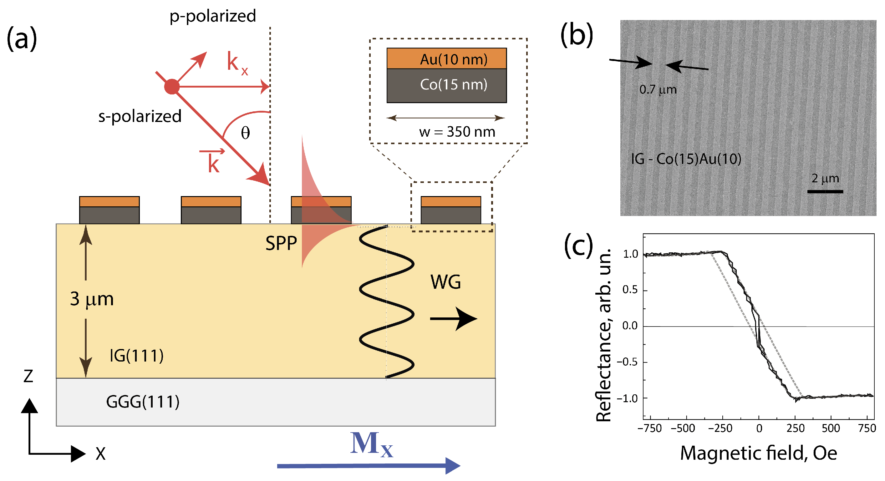
The second mode type includes waveguide (WG) ones that propagate in the magnetic dielectric slab with a high refractive index, as shown schematically in
Figure 1a. WG excitation can also be realized by exploiting a surface grating so that the in-plane wavevector of the WG mode is determined by the expression
, where
m is an integer. Contrary to surface plasmon polaritons, waveguide modes propagate in the bulk of a magnetic dielectric. It has been shown that both types of propagating modes reveal pronounced MO effects caused by the non-reciprocal dependence of their wavevectors on the DC magnetic field [
29].
Apart from common magneto-optical effects like Faraday or the magneto-optical Kerr effect (MOKE), it was shown that artificial structures also demonstrate a longitudinal magneto-optical intensity effect that can be even or odd in M and can be quite pronounced [
30,
31]. These findings enrich the list of unique MO effects specific to magneto-plasmonic structures. Without claiming to be a complete review of all the works in the field of magneto-plasmonics, we can underline that a great amount of research regarding the optical and magneto-optical effects in 1D metal/garnet MPCs has been performed. Starting from the magneto-optical Faraday effect, where first numerically and then experimentally resonant enhancement of MO activity was demonstrated [
7,
18,
32], qualitatively similar MPC properties were found as well for the in-plane magnetization of the structure in the transmission geometry described, e.g., in [
33,
34]. In these works, the principal role played by SPP and WG excitation is considered. Meanwhile, a comprehensive comparative experimental investigation of different types of optical and MO effects in a single MPC structure seems to be missing. Moreover, to the best of our knowledge, the resonant optical and MO responses in reflection from the 1D metal/garnet MPC and their relation to those in the transmission scheme have not been analyzed.
In this paper, we present research regarding the case of a 1D MPC consisting of a 3 μm thick rare-earth-substituted garnet layer with a 25 nm thick Co/Au grating of submicron period. We demonstrate the appearance of odd magneto-optical effects both in reflection and transmission modes under the in-plane magnetization of this structure and show that the most efficient scheme involves the excitation of the WG modes accompanied by anomalous transmission. The strong sensitivity of the resonant features of the considered 1D MPC to the geometry of the MO interaction is confirmed by both the experimental and theoretical results.
2. Materials and Methods
We studied the magneto-plasmonic crystals consisting of a 3 μm thick rare-earth-substituted iron garnet (
) film grown by liquid phase epitaxy on the (111) facet of a 500 μm thick gallium gadolinium garnet (GGG) substrate, with a 1D metal grating composed of a 15 nm thick Co layer and a 10 nm thick plasmonic Au layer placed above. The chemical composition of the garnet was checked by the EDX analysis (see
Figure S1). Co/Au film was formed by magnetron sputtering, and the surface grating with the stripe width of about 350 nm and the lattice period of 700 nm was created by electron beam lithography. The corresponding procedure is described in detail in [
35]. Prior to the deposition of Co/Au, the surface of garnet was subjected to chemical and RF plasma etching in order to increase the adhesion of metal. When performing the e-beam lithography with positive PMMA as the resist (200 nm thick), we used additional intermediate metal masks (25 nm vanadium and 10 nm thick copper) in order to compensate for different speeds of dry etching of resist and metals. Exposure was carried out via SUPRA 50 VP scanning electron microscope with an ELPHY PLUS (RAITH, Oberkochen, Germany) electronic lithography hardware and software complex by the inversion electron lithography method.
Geometrical parameters of the elements of 1D plasmonic crystals (not in the true scale) are shown in
Figure 1a, along with the introduced coordinate frame so that the Co/Au stripes are parallel to the
Y axis. As an example,
Figure 1b shows the scanning electron image of the surface of Co/Au grating with the period of 0.7 μm, the size of the surface structure being 100 μm × 100 μm.
Optical wavelength–angular spectroscopy of the MPC was performed using the radiation of a halogen lamp passed through a single-mode optical fiber, collimated by a 1 cm lens and polarized by a Glan–Taylor prism; then, the light beam was focused by a 5 cm lens on the structure into a spot of about 50 μm in diameter. The angle of incidence was varied in the interval from 0° up to 70° for the wavelength range of the probe beam from 400 nm to 1000 nm, which allowed to analyze the SPP and WG modes of different orders. The transmitted light was analyzed by the spectrometer APS-150 (Avesta, Troitsk, Russia), the angular gathering aperture of the system being ≈1.6°.
Magneto-optical effects were studied for the two geometries of application of the external magnetic field H, oriented in the plane of the structure in the transversal (along the
Y-axis) or longitudinal (along the
X-axis) direction. In the first case, the magnetization-induced variation in the intensity of the light beam is analyzed; it is characterized by the magnetic contrast as
where
is the (reflected or transmitted) intensity measured for the positive and negative saturating magnetic field
H of about 800 Oe. In the case of the longitudinal scheme, one expects rotation of the polarization plane of light that can be described by the complex angle
, where
and
are the s- and p-polarized components of the electric field of the light beam,
is the magnetization-induced rotation of the polarization plane, and
is the ellipticity [
36]. In order to reveal this effect, the Glan–Taylor prism (analyzer) was introduced prior to the detector; the optical axis was oriented at the angle of 45° with respect to the plane of incidence. When analyzing the experimental data, we neglected the magnetic-field-induced ellipticity of the transmitted beam and estimated the angle of the magnetization-induced rotation of the polarization plane of reflected or transmitted light.
Figure 1c shows the magnetic field dependence of the reflected light from the 1D MPC in the scheme of the longitudinal MOKE. One can see that the saturating magnetic field is about 250 Oe, so H = 800 Oe used in the spectral MO measurements described below corresponds to the saturated magnetization of garnet. The presence of two hysteresis-like features in this dependence is evidently associated with the two types of switching processes of remagnetization of the longitudinal and polar components of
. Interestingly, identical data are obtained for the pristine garnet film, which shows that the presence of cobalt in the surface grating does not affect the remagnetization process of garnet.
Calculations of the light interaction with MPC were performed by 2D finite element method using Comsol software (
https://www.comsol.com (accessed on 10 July 2025)). The simulations modelled the diffraction of an incident p-polarized plane wave on a 1D Co/Au grating covering a 3 μm garnet layer grown on a semi-infinite GGG substrate. We used geometrical parameters of the Co/Au grating corresponding to the experimental one and complex permittivities of Au and Co from Refs. [
37,
38]. The refractive indices of GGG and garnet were assumed to be dispersionless, with values of
and
, respectively. Optical absorption of both materials was neglected, justified for the near-infrared light. The gyration of garnet, g, in the magnetically saturated state was assumed to be g
, whereas the magnetic-induced non-diagonal elements of the cobalt permittivity tensor were omitted. The simulations were performed for the rectangular area with the width equal to the grating period
and the height of
(shown in
Figure S2), with imposed Floquet periodicity condition on x-boundaries and two
thick perfectly matched layers in the z-direction. The p-polarized plane light wave was incident obliquely onto the grating from the air semispace (
Figure 1a). The transmission/reflection spectra, as well as the magnetic effects in the light intensity and polarization state, were analyzed in the zero diffraction order.
3. Results
In this section, we present the results of experimental studies on the wavelength–angular spectra of optical and magneto-optical responses of the 1D MPC described above. In order to fully characterize the magneto-optical effects regarding the MPC, we performed experiments in both the transmission and reflection modes for the transversal and longitudinal magnetization and compared the results with those of numerical modeling. The main findings are that the excitation of the SPP or WG modes leads to the appearance of high-quality resonant features in the transmission (T) and reflection (R) spectra and to relevant enhancement of the MO response. Varying the angle of incidence of the probe beam enables tuning the resonant features to the required spectral range.
3.1. Transmission Spectroscopy
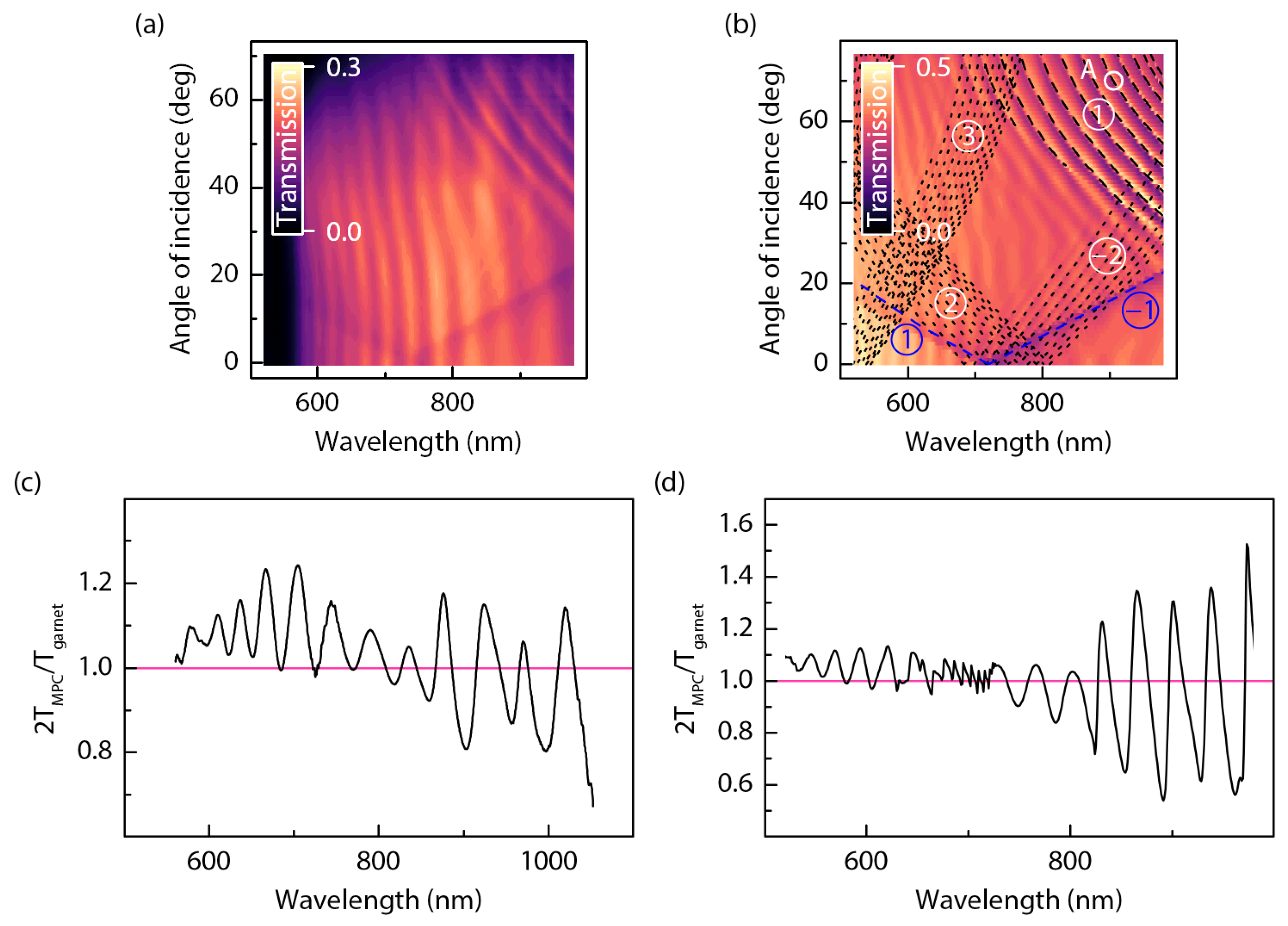
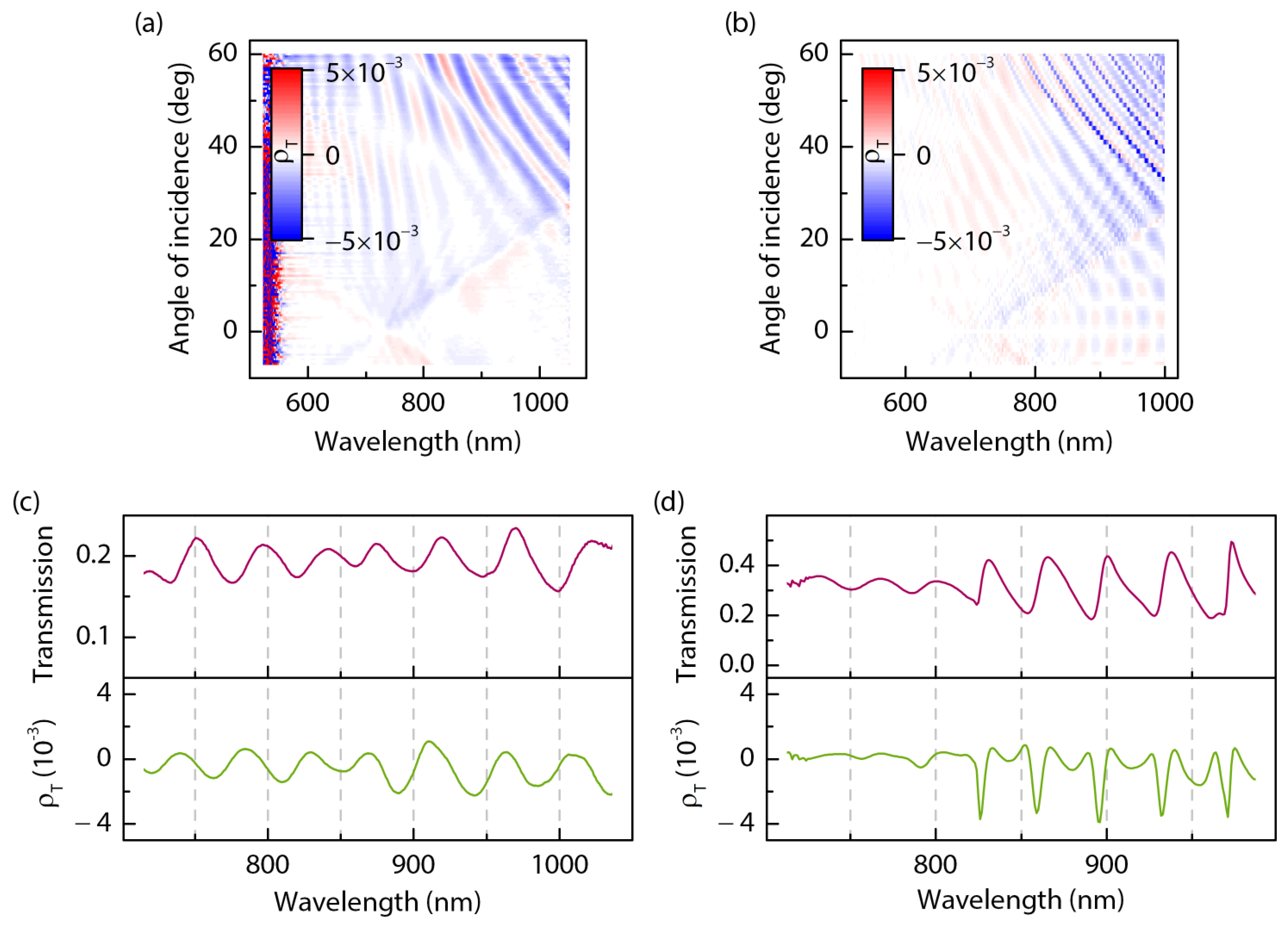
Figure 2a shows the wavelength–angular spectrum measured for the 1D MPC described above. It can be compared with the theoretical
spectrum shown in
Figure 2b, which is qualitatively similar. One can see three types of modes in the considered MPC.
(i) Periodic weak -dependent modulation of the transmission spectra evidently reveal the Fabry–Perot modes in the 3 μm thick garnet layer.
(ii) The SPPs of the first order (, blue line), denoted as and , appear as two branches meeting at for the wavelength of about 700 nm; they show typical linearity in and minima of T due to the enhanced absorption of the SPP wave. In the experiment, only surface plasmon polaritons corresponding to the “air–gold” interface were observed, while those located at the “cobalt–garnet” interface expected in the short-wavelength spectral region do not appear due to the garnet opacity at .
(iii) The WG modes of the diffraction orders. The modes of the first order denoted as can be seen at large and values (upper right corners of panels a and b), while the ones correspond to the IR wavelengths that are out of the detection range of our system. The WG modes of the second order, , appear as well, while their contribution is much less pronounced compared to the resonances of WG modes of the first order. Consistent with the modeling results, the WG modes appear as transmission maxima, contrary to the case of SPP excitation; thus, we assume WG-assisted anomalous transmission.
Figure 2c shows, at a larger scale, a portion of the MPC transmission spectrum for
with the most sharp WG modes’ resonances. The data are normalized by the transmission spectrum of the pristine garnet for the same
angle when accounting that half of its surface is covered by non-transparent metal stripes. One can see that the normalized transmission in the spectral maxima associated with the WG mode excitation (in the wavelength range 880–1040 nm) is about 110–115%, which is demonstrative of anomalous transmission. This effect also exists in the shorter wavelength range, where it is caused by a spectral shift in the transmission oscillation patterns of pristine garnet and MPC relative to each other due to the modification of the boundary conditions for the Fabry–Perot (FP) modes in the garnet layer in the presence of a metal grating. These observations are confirmed by calculations (
Figure 2d).
It is worth noting that the residual magnetization of the considered MPC is close to a value of zero, as indicated by the measurements shown in
Figure 1c; thus, it does not affect the transmission properties of the MPC.
3.2. Magneto-Optical Effects in 1D Au/Co/IG MPC for Longitudinal and Transversal Magnetization
As the next step, we analyzed the spectral features of the magneto-optical effects of the MPC in transmission and reflection as the in-plane magnetic field was applied in the Voigt (transversal) or longitudinal scheme.
3.2.1. Magneto-Optical Effect in the Longitudinal H Geometry in Transmission Through the 1D MPC
As is well known, the longitudinal magneto-optical Kerr effect (MOKE) consists of the magnetization-induced rotation of the polarization plane of light [
29]. As was demonstrated recently, a similar effect can appear in transmission through a magnetic film in an asymmetric environment including artificial magnetic structures of complicated designs [
30]. Below, we demonstrate that the 1D MPC described above also shows large resonant values of the MO response under the longitudinal magnetization in transmission geometry. We assert that the key role in this enhancement is due to the excitation of the WG modes in the garnet layer.
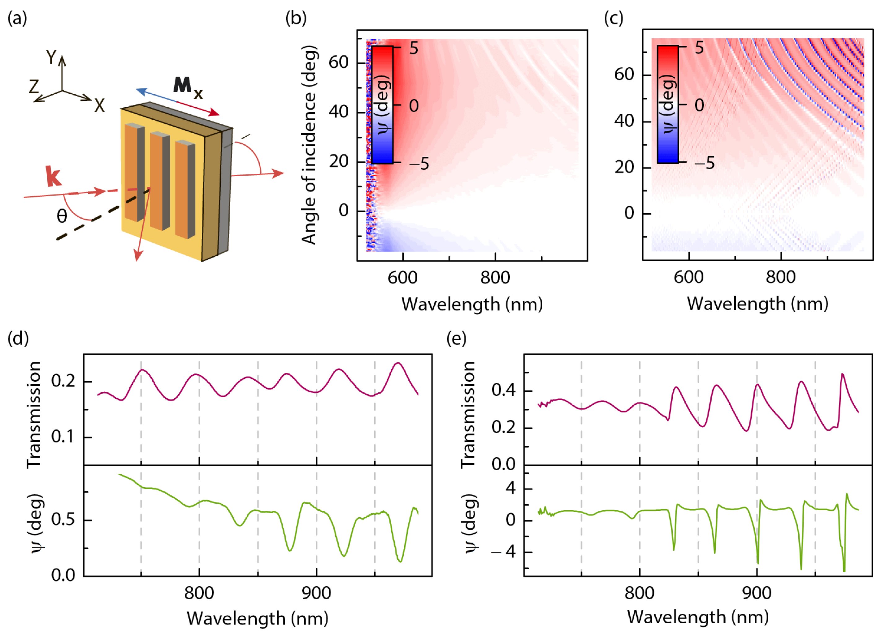
Figure 3a shows schematically the geometry of the experiment under longitudinal magnetization. Linearly p-polarized light is incident at the 1D MPC from the grating side, saturating the longitudinal magnetic field being formed by permanent magnets. Switching the polarity of the applied magnetic field is achieved by rotating the magnets around the sample in such a way that the magnetic field is kept in the plane of the sample and in the plane of incidence. For such experimental geometry at oblique light incidence, both the polar (Faraday) and longitudinal components of magnetization influence the nonresonant transmitted light. In turn, the waveguide modes propagating along the Ox-axis experience the polar (Faraday) component of the magnetization, which strongly affects the polarization of the resonant part of the transmitted light coupled with the waveguide modes.
We calculated the angle of magnetic-field-induced rotation of the polarization plane,
; the experimental and calculated
spectra are shown in
Figure 3b,c. They demonstrate (i)
0° close to zero angle of incidence
; (ii) the sign of
is the opposite for the positive and negative
values; (iii) the most pronounced resonant MO features are observed in the vicinity of the
modes for
and
750 nm; and (iv) a nonzero nonresonant background of
appears for inclined light incidence.
As seen, Fabry–Perot fringes appearing due to the finite thickness of the garnet film are almost not pronounced in the
spectrum. The observed sign change in the incident angle
leads to the inversion of the magnetization-induced polarization plane rotation, following the inversion of the direction of the polar component of M for the refracted light wave. At zero angle of incidence, this MO effect is absent in the relevant spectral ranges. In the vicinity of
at relatively high
values, a clear MO effect appears as sharp dips of
, indicating destructive interference of the MO effects from the WG modes and the rest of the garnet film (see
Figure 3b).
In order to compare the spectral position of the waveguide or plasmon mode with the spectral modulation of the MO response, we present the cross-sections of the spectra of transmission and
for the angle of incidence
= 50° (panels d,e of
Figure 3). One can see that excitation of the waveguide modes corresponds to the transmission maxima in
Figure 3d and minima of the MO response,
. Qualitatively similar behavior is revealed by the theoretical treatment of this structure, whereas the quality of the MO extrema is much higher compared to the experimental ones in
Figure 3d.
3.2.2. Longitudinal MOKE (Regarding Reflectionfrom the 1D MPC)
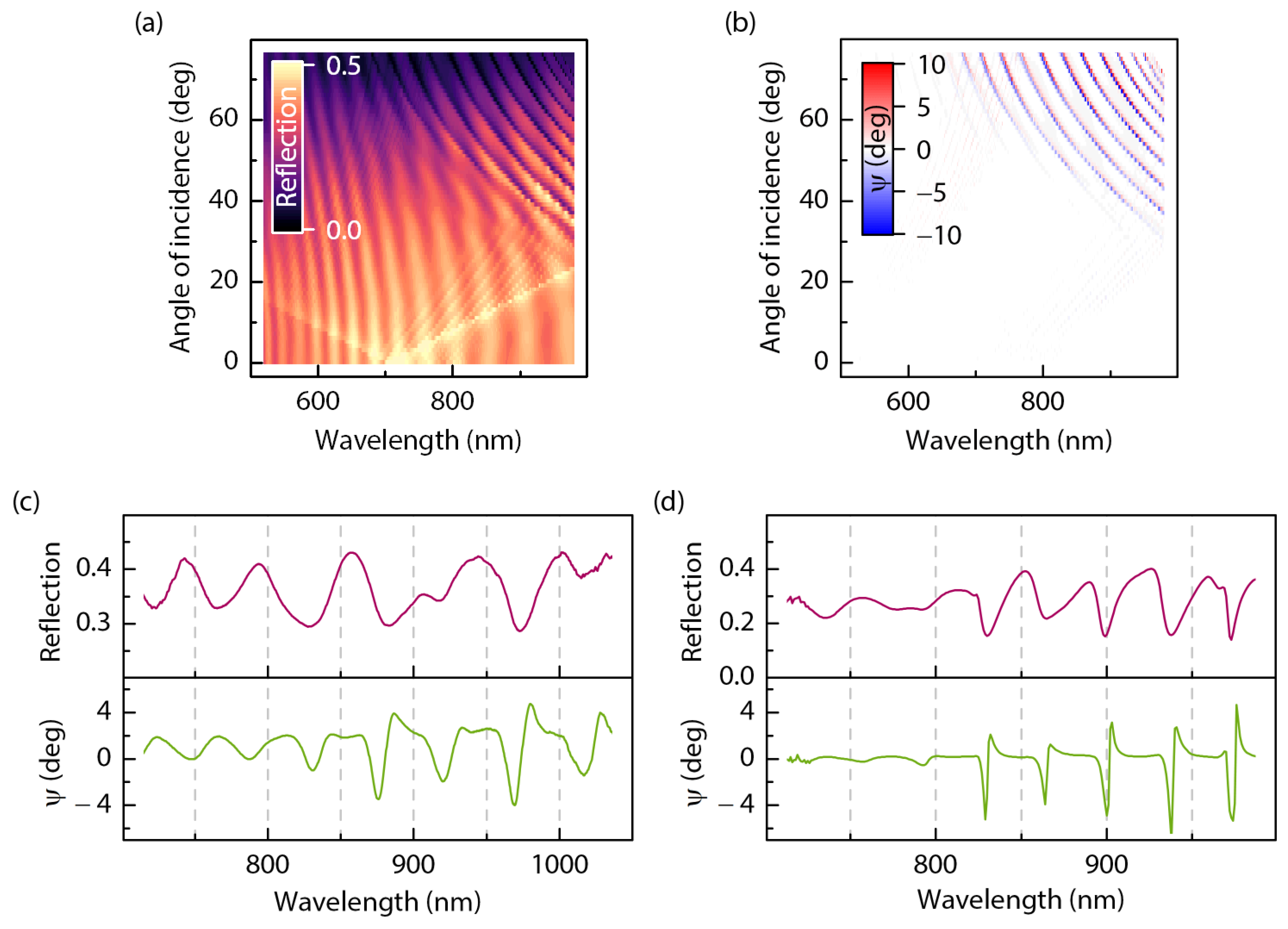
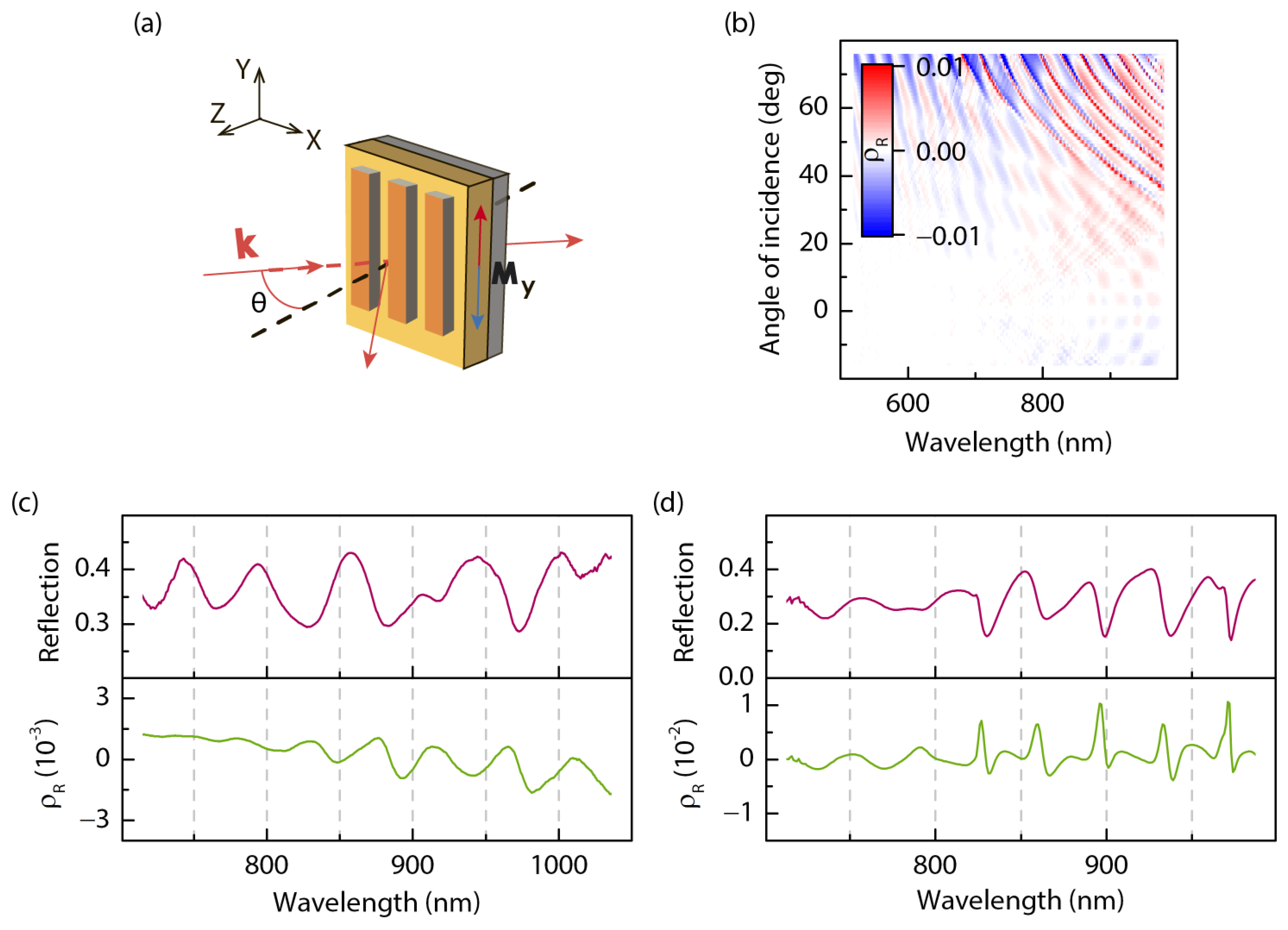
Figure 4 shows the results regarding the MO response of the 1D MPC for the “classical” geometry of the longitudinal MOKE as the angle of the magnetization-induced rotation of the polarization plane in reflection from the sample is estimated.
Figure 4a presents the calculated
reflection spectrum, which reveals resonant features similar to those of the transmission spectrum presented in
Figure 2. Namely, one can see the reflection maxima associated with the SPP excitation. Interference fringes as well as the WG-assisted reflection minima correspond to their positions found in the
transmission spectrum (see
Figure 2).
The calculated spectrum of the angle of the magnetization-induced rotation of the polarization plane of the reflected beam,
, is shown in
Figure 4b. It demonstrates qualitatively similar dependence to that of the transmission geometry with the resonant growth in
regarding the WG mode excitation. The cross-section of that spectrum along with the corresponding transmission
spectrum for
= 50° are shown in
Figure 4d. One can see that up to 4° (by absolute value) magnetization-induced rotation of the polarization plane is observed as sharp peaks close to the reflection WG-assisted minima. As seen, an important advantage of the reflection geometry is a clear polarization conversion effect in the WG modes compared with the transmission geometry due to the absence of a nonresonant background.
Qualitatively similar effects are observed in the experiment as demonstrated in
Figure 4c, which shows measured spectra of the transmission and
. At the same time, the absolute value of the resonant MO effect is smaller nearly by an order of magnitude compared to the theoretical predictions, which is evidently caused by the insufficient quality of the structure, uncertainty in the gyration value of the garnet, and the absorption of the garnet, which was disregarded in the simulations.
3.2.3. Magneto-Optical Effect in the Transversal MOKE Geometry
Figure 5 shows the results of optical and magneto-optical experiments on the 1D MPC in the geometry of the transversal MOKE. We analyzed the magnetization-induced modulation of the intensity of the reflected light. The calculated
spectrum of the magnetic contrast
(introduced by Equation (
2)) is presented in
Figure 5b. It demonstrates a number of spectral features; the most pronounced are associated with WG mode excitation, appearing as the reflection minima (
Figure 4a). Close to them, strong modulation of the magnetic contrast is attained, so the sign of
is changed as well. The value of the effect is of the order of
–
, which is typical for the transversal MOKE for various types of magnetic materials.
The theoretical calculations reveal an asymmetric Fano-type shape of resonant WG-associated features with a few times larger amplitude and larger quality factor that is driven by the imperfection of the experimental structures and the optical absorption of garnet. This is clearly seen regarding the experimental and theoretical spectra of the magnetic contrast for the angle of incidence
= 50° shown in panels c and d of
Figure 4. As seen, the SPPs mediated by the “gold–air” interface almost do not contribute to the magnetic contrast of the transversal MOKE.
3.2.4. Linear Magneto-Optical Intensity Effect in the Voigt Geometry
Analogous magnetic studies were performed as well in transmission through the structure, i.e., in the Voigt geometry; they are summarized in
Figure 6. Contrary to the classical Voigt effect that is of the second order in M, we analyzed intensity variations that are linear in magnetization and measured the intensity magnetic contrast,
, defined by Equation (
2). The experimental and calculated
spectra of
are shown in panels a and b, correspondingly, whereas, in panels c and d, the wavelength spectra of transmission and magnetic contrast
for the angle of incidence
= 50° are compared. In addition to the resonant MO response of the MPC close to the WG resonant modes, a pronounced modulation of the magnetic contrast is seen in the vicinity of the SPP modes that appear as the enhancement and sign inversion of
. As expected for such resonances, the effect is opposite in sign for the positive and negative
values [
39].
It is worth noting that the magneto-optical effect associated with the Fabry–Perot modes in the garnet film is the most pronounced in this geometry. Really, the maximal value of the magnetic contrast attained at the interference fringes approaches the contrast value for the SPP features. The strongest intensity variation is observed again close to the WG modes of the first order.
4. Discussion
Thus, we have observed that the fabricated MPC supports the excitation of the two types of propagating modes, namely SPP and guided ones, as well as the Fabry–Perot modes in the 3 μm thick garnet layer. The propagation of surface plasmons is accompanied by increased absorption in the Co/Au layer, appearing as pronounced transmission minima, their resonant wavelength being an almost linear function of the angle of incidence. The quality factor of the SPP modes is relatively modest, which is attributed to the small average thickness of the metal gratings composed in part of the Co layer with high ohmic losses. Moreover, in the considered spectral range, the SPPs are related to the “gold–air” interface. Thus, the local field effects associated with the SPP propagation are also not high, and we did not expect strong SPP-assisted MO effects. Note that, in our samples, the SPP resonances of the first order are studied in the wavelength range > 600 nm, corresponding to the transparency of the garnet layer. Thus, its contribution to the absorption of the SPP is negligible.
Waveguide modes are the most attractive features in the considered MPC that reveal the most sharp resonances appearing as maxima in transmission spectra contrary to the SPP case. This is seen in the experiment and is confirmed by the results of modeling (see
Figure 2). Thus, we suppose that, in addition to realizing the phase matching of the waveguide mode propagation in the optically dense garnet, the grating with wide stripes is responsible for anomalous transmission. The strongest MO effect is achieved for the
family of modes in the spectral range of high transparency of the garnet film (850–1000 nm); the normalized transmittance exceeds the unity by a value of about 15%.
Magneto-optical effects are studied for the in-plane magnetic field applied to the MPC in the transversal or longitudinal schemes. One can see that, for both the reflection and transmission experimental schemes, magneto-optical effects for zero incident angle vanish within the experimental accuracy (see
Figure 2,
Figure 3 and
Figure 4). Similarly, the inversion of the sign of the magneto-optical effects for the pristine garnet film and for the 1D MPC structures under changing the incident angle
is consistent with the experimental observations and numerical treatment.
It turned out that the intensity MO effects for the transversal magnetization are of the same order of magnitude in both the reflection and transmission of light and are enhanced in the vicinity of the WG or FP modes. In both cases, the MO intensity modulation is caused by oddmagnetization changes in the resonant modes’ dispersion. It turned out that the resonant WG modes’ assisted MO effects are comparable or stronger to the FP ones, and this is the case regarding the experimental observations, especially for the transmission scheme.
Regarding longitudinal magnetization, the Fabry–Perot modes do not appear in the spectra of the (linear in H) MO effect. As for the geometry of the applied magnetic field, the dispersion remains independent regarding the sign of H for the p-polarized incident beam. In turn, the WG modes, excited via first- and second-order diffraction, are well pronounced in the spectra of the MO polarization plane rotation, i.e., regarding the angle, at least in modeling.
We excite the WG modes with the wavevector parallel to the reciprocal lattice vector. The longitudinal magnetic field affects their polarization plane in a similar way as in the common Faraday effect and provides the strongest MO resonant effect.
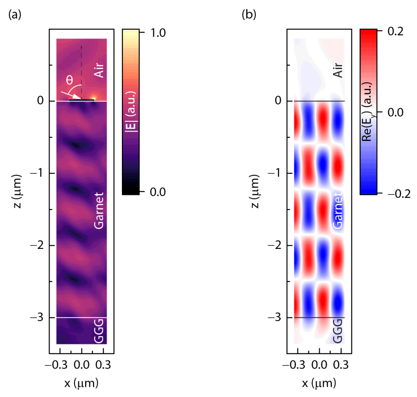
Figure 7 illustrates the calculated spatial distributions of an electric field under first-order diffraction-induced excitation of the fifth WG mode, corresponding to the A point in
Figure 2b, i.e., at
and
. As seen, the field distribution manifests the propagation of a WG mode with five antinodes in the guiding garnet layer (
Figure 7a). Its longitudinal magnetization results in the appearance of the strong transverse
component of the field inside the garnet as well as in the surrounding semispaces, demonstrating the polarization plane rotation in the transmitted and reflected light (
Figure 7b); more details
In the transverse scheme of the magnetic field application, the enhancement of the magneto-optical effects close to the WG modes’ excitation is caused by the corresponding magnetization-induced modulation of their propagation constants in the garnet layer, thus shifting the resonant conditions for the WG mode excitation under magnetic field application.
We suppose that the most attractive features of the resonant spectra of the studied MPC are the sharp drops in the spectra of transmission, reflection, and longitudinal MO effect in the vicinity of the waveguide modes. This resonant behavior of the MPC is promising first of all for the composition of tunable narrowband magneto-optical filters and switchers operating both in reflection and transmission modes. Further optimization of the process of WG mode excitation and magnetic-field control over their propagation conditions can improve the practical implementation of MPC-based photonic devices through increasing the modes’ quality factor and the MO activity of the dielectric layer.
5. Conclusions
Summing up, we have studied the optical and magneto-optical response of a magneto-plasmonic crystal (MPC) composed of a 1D Co/Au grating on a rare-earth-substituted garnet film. The experimental and theoretical wavelength–angular MPC spectra reveal the excitation of two types of propagating resonant modes: surface plasmon polaritons and a family of waveguide modes of different orders. Enhanced magneto-optical effects with opposite signs are observed in the spectral vicinity of the plasmon–polariton and waveguide modes in the reflection and transmission geometries under the application of an in-plane magnetic field. We demonstrate that the strongest WG mode-assisted magneto-optical effect is attained for the longitudinal magnetization, the corresponding modulation of the polarization plane rotation being about 0.5°.
Other attractive effects specific to the studied MPC include high-quality resonances in the spectra of transmission, MO effects, and anomalous transmission of about 115% accompanying the excitation of the WG modes. These features are promising for a number of applications, such as tunable optical filters, sensors, and routers.

 ,
, 