Article

Aberration Theoretical Principle of Broadband Multilayer Refractive–Diffractive Optical Elements by Polychromatic Integral Aberration Method

School of Optoelectronic Engineering, Changchun University of Science and Technology, Changchun 130022, China
*
Authors to whom correspondence should be addressed.
Photonics 2025, 12(7), 690; https://doi.org/10.3390/photonics12070690
Submission received: 28 May 2025 / Revised: 6 July 2025 / Accepted: 7 July 2025 / Published: 8 July 2025

Abstract

Multilayer diffractive optical elements (MLDOEs), which have broadband imaging performance, are widely used in lightweight and compact optical systems on the surface of the refractive lenses forming refractive–diffractive lenses. However, current research is generally limited to its broadband diffraction efficiency distribution and rarely involves the study of the imaging quality of multilayer refractive–diffractive optical elements in the broadband. The lack of research on its aberration principle and the absence of methods on how to achieve average aberration control in the broadband have led to a decline in imaging quality when it is applied to the optical system. Therefore, in this paper, we have derived in detail the aberration theory of multilayer refractive–diffractive optical elements and proposed the polychromatic integral aberration (PIA) method to evaluate the aberration characteristics of multilayer diffraction optical elements in the whole broadband. First, we start with the aberrations of diffractive optical elements in the air, and then derive the overall aberrations applied to multilayer refractive–diffractive optical elements. Then, based on the performance of the average aberrations throughout the entire broadband, a broadband aberration evaluation method named PIA is proposed. Finally, the design of traditional multilayer diffraction optical elements, the design of refractive–diffractive multilayer optical elements based on the derivation, and the design of multilayer refraction diffraction optical elements under the PIA method are compared. The results show that the multilayer refractive–diffractive optical element designed by PIA can effectively achieve aberration control and balanced aberration performance in the whole broadband. This research provides a practical and feasible path for exploring the imaging quality of broadband multilayer refractive–diffractive optical elements.

1. Introduction

Multilayer diffractive optical elements, due to their excellent broadband properties [1], arbitrary phase distribution properties [2,3], temperature stability properties [4], and negative dispersion properties [5], are widely used in the design of imaging systems [6,7]. Especially when multilayer diffractive optical elements are designed on refractive lenses to form multilayer refractive–diffractive optical elements to carry more functions, the number of system lenses can be effectively reduced to achieve the purpose of lightweight system design [8].
Multilayer refractive–diffractive optical elements can achieve stable imaging in the broadband through phase transformation [9,10]. Buralli et al. [11] defined the design evaluation method named polychromatic integral diffraction efficiency (PIDE) for MLDOEs with broadband imaging. Broadband MLDOEs are widely used. Piao et al. [4] has conducted research on the design of the optimal diffraction efficiency of multilayer diffractive optical elements in a wide temperature range and broadband. Yang et al. [12] conducted in-depth research on the broadband optimization of multilayer diffractive optical elements under extended scalar diffraction theory. However, high diffraction efficiency alone is not sufficient to guarantee excellent imaging quality. Even with extremely high diffraction efficiency, if aberrations are not effectively corrected, system performance will still be limited [13]. For instance, severe spherical aberration or coma can lead to blurred or distorted images [14], even when energy utilization is efficient, preventing the system from meeting the demands of high-precision imaging. Therefore, in-depth research into the aberration characteristics of MLDOEs and the development of effective control methods are crucial for achieving high-performance broadband imaging. In conclusion, the research on broadband multilayer diffractive optical elements has become a hot topic.
Overall, it can be found that the research on multilayer refractive–diffractive optical elements is limited to the study of their diffraction efficiency. For a multilayer refractive–diffractive optical element that performs both diopter and broadband imaging, the study of its aberration (corresponding to the imaging quality) is extremely necessary. However, to the best of our knowledge, there is no overall derivation of the aberration of multilayer refraction–diffraction optical elements and no research on how to achieve the aberration control theory in the broadband. This gap limits the application of MLDOEs in precision imaging, especially in fields with stringent imaging quality requirements, such as high-resolution spectrometers, medical endoscopes, and aerospace remote sensing. In these applications, relying solely on high diffraction efficiency is insufficient; the system must simultaneously exhibit extremely low aberrations to ensure image clarity and accuracy. Therefore, to overcome this issue, establishing a comprehensive aberration theory for multilayer diffractive optical elements and proposing effective broadband aberration evaluation methods are crucial for advancing the practical application of MLDOEs.
Considering the above factors, it is extremely necessary to derive the aberration theory of multilayer refractive–diffractive optical elements and propose a way to evaluate the overall aberration in the broadband. Therefore, in this paper, the aberration derivation applied to the refractive–diffractive MLDOEs was obtained. Then, the polychromatic integral aberration (PIA) method was proposed to evaluate aberration control in the broadband. The composition of other sections of the thesis is as follows: In Section 2, the derivation of the aberrations of DOEs in air as the basics for the research is recalled. In Section 3, the aberration expression of the multilayer diffractive optical element is derived in detail. Then, we combined the aspheric parameters of the refractive substrate and the diffractive correction parameters and obtained the aberration derivation of the multilayer refractive–diffractive optical element. By solving the average aberration in the broadband, the aberration evaluation model in the broadband—polychromatic integral aberration (PIA)—is proposed. In Section 4, the results of the conventional multilayer refractive–diffractive optical element design method, the multilayer refractive–diffractive optical element design method only by the proposed the aberration model, and the multilayer refractive–diffractive optical element design method using the PIA method are compared and discussed. In Section 5, the research is summarized.

2. Aberration Theory of Diffractive Optical Elements in Air

For the detailed derivation of refraction aberrations, please refer to Appendix A in this paper; the letters in this section also refer to Appendix A. 
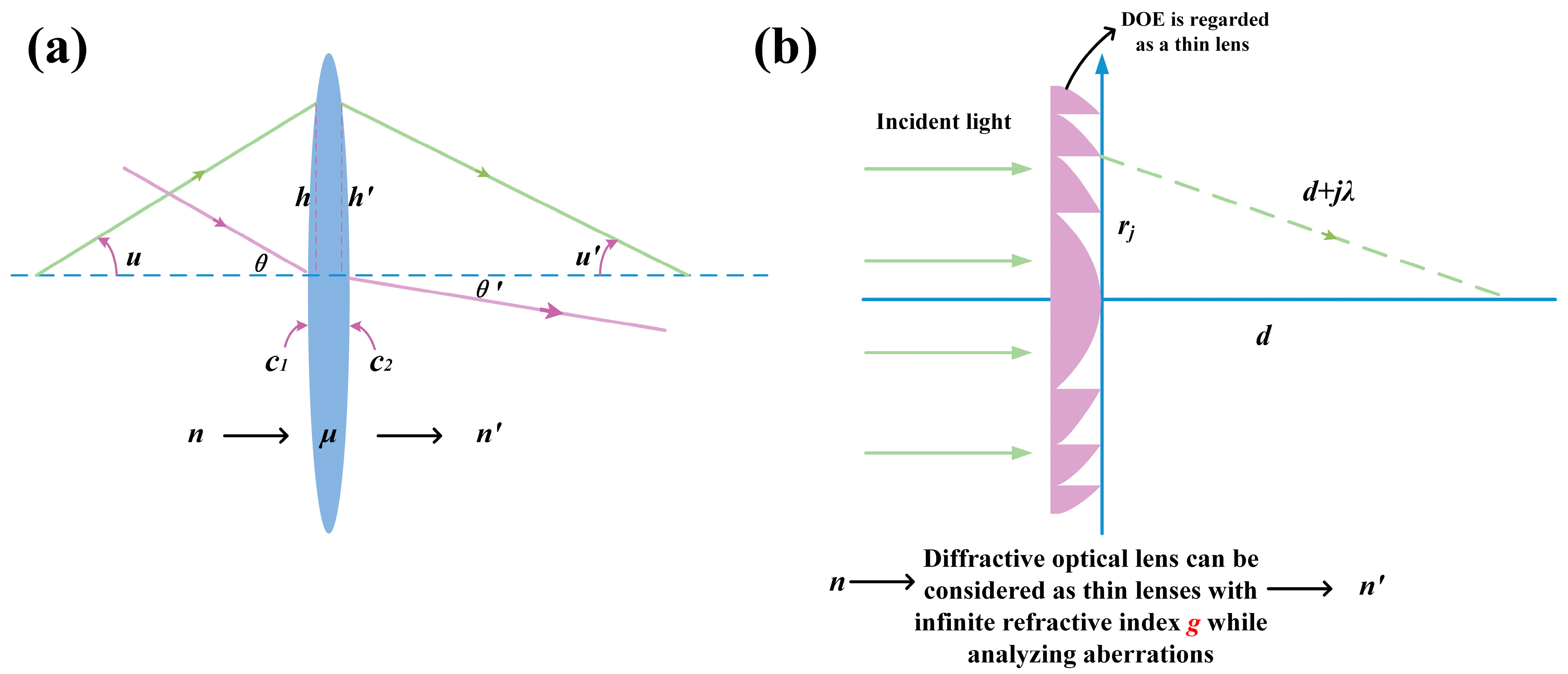
Figure 1a shows the optical path diagram of the refractive lenses. c1 is the curvature the refractive lens’s front surface. c2 is the curvature of the refractive lens’s back surface. u and u are the convergence angles of the incidence and exit light. n and n are the refractive indices of the front media and back media. θ and θ are the angles of the incidence and exit light. h and h are the heights of the incidence and exit light.
As shown in Figure 1b, when employing a diffractive optical element as an aberration correction element, its behavior can be approximated by modeling it as a thin optical element with an infinite refractive index (its refractive index tends to ∞) property. This approximate method, known as the “infinite refractive index thin lens model”, is widely used in the initial aberration analysis of diffraction optical elements. Its core concept lies in the fact that the diffraction element modulates the phase of the light wave through its microstructure. This modulation effect is, in a macroscopic sense, equivalent to a lens with a specific focal length but a thickness approaching zero. Since the diffraction effect itself does not depend on the refractive index of the medium, it can be hypothetically assumed to have an infinite refractive index, thereby enabling instantaneous and ideal refraction of light when it passes through the diffraction surface. This modeling method significantly simplifies the aberration calculation, allowing it to be consistent in form with the traditional refractive aberration theory and facilitating unified analysis. However, it should be noted that this approximation may have limitations when dealing with higher-order aberrations or diffraction efficiency issues, but it has significant advantages for qualitative analysis and preliminary design of primary aberrations. At this point, the front and back surface curvatures c 1 , c 2 c s .
So, for the diffractive optical elements in air, i.e., n = n = 1 , the diopter of the DOE, which is considered as a thin lens, can be expressed as follows:
K m = ( g n ) c 1 c 2 ,
where g is the refractive index of the DOE.
Then, further define U by the shape factor X (defined in Appendix A) as
U = X g n = c 1 + c 2 K = 2 c s K .
Thus, Equation (2) can be used in Equations (A4), (A6), and (A8), which are shown in Appendix A. For example, when substituting g → ∞ and Equation (2) into Equations (A4), (A6), and (A8), a 1 n X n 3 = 1 μ 2 n 2 ( μ n ) 2 n 2 μ n 2 X n 3 = 0 , a 5 n X n 2 = 1 μ μ + 2 n ( μ n ) 2 + μ + 2 n μ n 2 X n 2 = 1 μ μ + 2 n 1 + μ + 2 n 1 U 2 = 2 U 2 (μ = g). Then, further simplify the aberrations as
S I , D = h 4 K 3 4 1 + U 2 4 U Y + 3 Y 2 S I I , D = h 2 K 2 H 2 U 2 Y S I I I , D = H 2 K n 2 S I V , D = 0 S V , D = 0

3. Broadband Aberration Theory for Multilayer Refractive–Diffractive Optical Elements

3.1. Aberration Derivation for Multilayer Diffractive Optical Elements

All the letters in this chapter refer to Figure 2. For a refractive–diffractive lens, the front and back media refractive indices of diffractive elements are not the same. For the first layer of diffractive optical elements, the diffraction structure is designed on the rear surface of the refractive lens. For the diffraction structure, the refractive index of the medium in front is the refractive index n1 of the refractive lens, and the refractive index of the medium in the rear is the refractive index of the environment in the rear (i.e., in air as 1). For the second layer of diffractive optical elements, the refracting structure is designed on the front surface of the refracting lens. For the diffraction structure, the refractive index of the front medium is the refractive index of the front environment (i.e., in air as 1), and the refractive index of the rear medium is the refractive index n2 of the refractive lens. Obviously, the conventional diffraction aberration principle in air is not applicable under this circumstance. This situation of refractive index mismatch in the media is an inherent characteristic of the diffraction–refraction hybrid system, which makes the traditional aberration theories based on a single medium or the air–medium interface no longer fully applicable. Figure 2 clearly depicts this complex structure, in which the diffraction surface is embedded in the refractive element, with different refractive indices of the media before and after the surface. This indicates that when light passes through the diffraction surface, it not only undergoes phase modulation by the diffraction structure but also is affected by the difference in the refractive indices of the surrounding media.
Therefore, it is necessary to derive a theoretical theory of diffraction aberration when the refractive indices of the front and rear media are different. In this subsection, we will first discuss this model in detail. Firstly, the diffractive optical element as a thin lens at this time is considered. When the refractive indices of the front and rear media are not equal, its diopter can be expressed as follows:
g n 1 c 1 + ( 1 g ) c 2 = K m 1 g 1 c 1 + ( n 2 g ) c 2 = K m 2 .
where K m 1 and K m 2 are the diopters of the diffractive optical elements of each layer. g is the refractive index of the diffractive optical elements of the first and the second layer (g → ∞).
Like the derivation of Equation (2), we can further organize Equation (4) to obtain the form we want as
g n 1 c f 1 c b 1 = K m 1 + n 1 1 c f 1 = K m 1 + n 1 1 c s 1 g 1 c f 1 c b 1 = K m 1 + n 1 1 c b 1 = K m 1 + n 1 1 c s 1 g 1 c f 2 c b 2 = K m 2 + 1 n 2 c f 2 = K m 2 + 1 n 2 c s 2 g n 2 c f 2 c b 2 = K m 2 + 1 n 2 c b 2 = K m 2 + 1 n 2 c s 2 .
Based on Equation (A1) in Appendix A, the further deformation form of the shape factor can be obtained as follows:
B m 1 = X g n 1 = X g 1 = c f 1 + c b 1 K m 1 + n 1 1 c s 1 = 2 c s 1 K m 1 + n 1 1 c s 1 B m 2 = X g 1 = X g n 2 = c f 2 + c b 2 K m 2 + 1 n 2 c s = 2 c s 2 K m 2 + 1 n 2 c s 2 .
Finally, the whole diffraction aberration expressions are expressed as the combination of each layer ( S D 1 represents the diffraction aberration of the first layer and S D 2 represents the diffraction aberration of the second layer):
S I , D = S I , D 1 + S I , D 2 = h 1 4 K m 1 3 4 1 + B m 1 2 4 B m 1 Y m 1 + 3 Y m 1 2 + h 2 4 K m 2 3 4 1 + B m 2 2 4 B m 2 Y m 2 + 3 Y m 2 2 S I I , D = S I I , D 1 + S I I , D 2 = h 1 2 K m 1 2 H 1 2 B m 1 2 Y m 1 + h 2 2 K m 2 2 H 2 2 B m 2 2 Y m 2 S I I I , D = S I I I , D 1 + S I I I , D 2 = 1 2 H 1 2 K m 1 1 n 1 2 + 1 1 n 1 2 1 Y m 1 + 1 2 H 2 2 K m 2 1 + 1 n 2 2 1 1 n 2 2 Y m 2 S I V , D = S I V , D 1 + S I V , D 2 = 0 S V , D = S V , D 1 + S V , D 2 = H 1 3 h 1 2 1 n 1 2 1 + H 2 3 h 2 2 1 1 n 2 2 .

3.2. The Aberration Control Model for Multilayer Refractive–Diffractive Optical Elements

For multilayer refractive–diffractive optical elements, it is obvious that their aberrations should include four aspects: (1) The refractive lens part of the first layer; (2) The diffractive lens part designed on the rear surface of the first layer refracting lens; (3) The diffractive lens part designed on the front surface of the second layer refractive lens; (4) The refractive lens part of the second layer. Then, the overall aberration is expressed as follows:
S t o t a l = S D 1 + S R 1 + S D 2 + S R 2 .
At this point:
(1)
For the first layer, the front medium is air (refractive index 1) and the rear medium is the refractive lens (refractive index n1), i.e., B m 1 = 2 c s 1 K m 1 + 1 n 1 c s 1 , B m 2 = 2 c s 2 K m 2 + 1 n 2 c s 2 . For the refractive lens, the diffraction base curvature is regarded as the curvature of the back surface of the refractive lens, i.e., c 2 = c s 1 , X = c f 1 + c s 1 c f 1 c s 1 .
(2)
For the second layer, the front medium is the pre-lens environment (refractive index n) and the rear medium is the refractive lens (refractive index µ), i.e., B m 2 = 2 c s 2 K m 2 + 1 n 2 c s 2 . For the refractive lens, the diffraction base curvature is regarded as the curvature of the refractive lens’s front surface, i.e., c 2 = c s 2 , X = c s 2 + c b 2 c s 2 c b 2 .
Then, the multilayer refractive–diffractive lens aberration expression can be obtained as
S I , T o t a l = h 1 4 K m 1 3 4 1 + B m 1 2 4 B m 1 Y m 1 + 3 Y m 1 2 + h 2 4 K m 2 3 4 1 + B m 2 2 4 B m 2 Y m 2 + 3 Y m 2 2 + 1 8 h 1 4 K 1 3 a 11 X 1 3 + a 21 Y 1 3 + a 31 X 1 2 Y 1 + a 41 X 1 Y 1 2 + a 51 X 1 2 + a 61 Y 1 2 + a 71 X 1 Y 1 + a 81 X 1 + a 91 Y 1 + a 101 + 1 8 h 2 4 K 2 3 a 12 X 2 3 + a 22 Y 2 3 + a 32 X 2 2 Y 2 + a 42 X 2 Y 2 2 + a 52 X 2 2 + a 62 Y 2 2 + a 72 X 2 Y 2 + a 82 X 2 + a 92 Y 2 + a 102 S I I , T o t a l = h 1 2 K m 1 2 H 1 2 B m 1 2 Y m 1 + h 2 2 K m 2 2 H 2 2 B m 2 2 Y m 2 + 1 4 h 1 2 K 1 2 H 1 p 11 X 1 2 + p 21 Y 1 2 + p 31 X 1 Y 1 + p 41 X 1 + p 51 Y 1 + p 61 + 1 4 h 2 2 K 2 2 H 2 p 12 X 2 2 + p 22 Y 2 2 + p 32 X 2 Y 2 + p 42 X 2 + p 52 Y 2 + p 62 S I I I , T o t a l = 1 2 H 1 2 K m 1 1 n 1 2 + 1 1 n 1 2 1 Y m 1 + 1 2 H 2 2 K m 2 1 + 1 n 2 2 1 1 n 2 2 Y m 2 + H 1 2 K 1 + H 2 2 K 2 S I V , T o t a l = H 1 2 K 2 n 1 + H 2 2 K 2 n 2 S V , T o t a l = H 1 3 h 1 2 1 n 1 2 1 + H 2 3 h 2 2 1 1 n 2 2 ,
where h1 = h2 and H1 = H2.
From Equation (9), by adjusting the corresponding parameters, the corresponding aberration results can be obtained. Next, we will optimize the two major aberrations—spherical aberration and coma—in multilayer diffractive optical elements to further analyze the model. In the design of optical systems, spherical aberration and coma are two types of monochromatic aberrations that are typically the first to be corrected. Spherical aberration affects the imaging quality of the system along the axial direction, causing point light sources to appear as diffused spots, while coma affects the imaging quality of off-axis object points, making point light sources appear as comet-shaped light spots. The effective control of these aberrations is crucial for achieving clear and uniform imaging. Through in-depth analysis of Equation (9), we can identify the key design parameters that affect these aberrations, such as the curvature radius of the lens, the refractive index of the material, the phase distribution of the diffraction structure, etc. Especially in multilayer refractive–diffractive systems, the geometric parameters of the refractive part and the phase modulation parameters of the diffraction part jointly determine the aberration characteristics of the system. Therefore, by optimizing these parameters, we can achieve fine control of spherical aberration and coma, thereby improving the overall imaging performance of the system.
Firstly, the control parameters of the aspheric surface are added. Usually, within the Seidel aberration system range, only the cone coefficient and the fourth-order aspheric surface coefficient are added. Therefore, the corresponding influence on the spherical aberration regulation is obtained as follows: n n h 4 R 3 Q + 8 ε c 3 , where Q is the conic and ε is the fourth-order aspheric parameter. Correspondingly, for each layer of diffractive optical elements, adding a diffractive control coefficient to the diffractive optical element part has an impact on spherical aberration as follows: 8 m λ A h 4 , where A represents the fourth-order diffraction parameter. As for coma, due to the stop–shift principle, the change in spherical aberration correction will lead to an increase in coma as follows: n n t κ n h h 4 R 3 Q + 8 ε c 3 , where κ is the view angle. In conclusion, the comprehensive aberration control model with the refractive aspheric control coefficient and the diffractive control coefficient added is expressed as follows:
S I , T o t a l = h 1 4 K m 1 3 4 1 + B m 1 2 4 B m 1 Y m 1 + 3 Y m 1 2 + h 2 4 K m 2 3 4 1 + B m 2 2 4 B m 2 Y m 2 + 3 Y m 2 2 + 1 8 h 1 4 K 1 3 a 11 X 1 3 + a 21 Y 1 3 + a 31 X 1 2 Y 1 + a 41 X 1 Y 1 2 + a 51 X 1 2 + a 61 Y 1 2 + a 71 X 1 Y 1 + a 81 X 1 + a 91 Y 1 + a 101 + 1 8 h 2 4 K 2 3 a 12 X 2 3 + a 22 Y 2 3 + a 32 X 2 2 Y 2 + a 42 X 2 Y 2 2 + a 52 X 2 2 + a 62 Y 2 2 + a 72 X 2 Y 2 + a 82 X 2 + a 92 Y 2 + a 102 8 m 1 λ A 1 h 1 4 8 m 2 λ A 2 h 2 4 + n 1 1 h 1 4 R f 1 3 Q f 1 + 8 ε f 1 c f 1 3 + 1 n 1 h 1 4 R s 1 3 Q b 1 + 8 ε b 1 c s 1 3 + n 2 1 h 2 4 R s 2 3 Q f 2 + 8 ε f 2 c s 2 3 + 1 n 2 h 2 4 R b 2 3 Q b 2 + 8 ε b 2 c b 2 3 S I I , T o t a l = h 1 2 K m 1 2 H 1 2 B m 1 2 Y m 1 + h 2 2 K m 2 2 H 2 2 B m 2 2 Y m 2 + 1 4 h 1 2 K 1 2 H 1 p 11 X 1 2 + p 21 Y 1 2 + p 31 X 1 Y 1 + p 41 X 1 + p 51 Y 1 + p 61 + 1 4 h 2 2 K 2 2 H 2 p 12 X 2 2 + p 22 Y 2 2 + p 32 X 2 Y 2 + p 42 X 2 + p 52 Y 2 + p 62 + 1 n 1 t 1 κ n 1 h 1 h 1 4 R s 1 3 Q b 1 + 8 ε b 1 c s 1 3 + 1 n 2 t 2 κ n 2 h 2 h 2 4 R b 2 3 Q b 2 + 8 ε b 2 c b 2 3 .

3.3. Broadband Aberration Evaluation Method—Polychromatic Integral Aberration (PIA)

Obviously, Equation (10) can only be solved for the optimal design result at a single wavelength. However, for an example like optical systems designed in the visible light waveband, whose band is usually 450–700 nm, considering only the optimal design result at one wavelength cannot simultaneously meet the good imaging effect across the entire waveband. Therefore, a method to evaluate the aberration results in the broadband based on the average in the waveband is proposed. The evaluation equation PIA can be expressed as follows:
S ¯ = 1 λ max λ min λ min λ max S T o t a l ( λ ) d λ
From Equations (10) and (11), when the parameters such as the curvature radius of the refraction part, the incident height, the period radius, and the refractive index of each layer are determined, the average aberration in the broadband is only related to A1 and A2. By regulating A1 and A2, the corresponding aberration regulation results can be obtained. The PIA provides a comprehensive aberration evaluation metric by integrating the aberrations at different wavelengths. The core idea of this method is to transform the broadband aberration problem into a multi-objective optimization problem, aiming to achieve balance in the aberration distribution across the entire wavelength range rather than merely pursuing the extremum at a single wavelength. By reasonably allocating weights to the contributions of aberrations at different wavelengths, the PIA can find a solution that performs well throughout the entire wavelength range, thereby significantly enhancing the practical value and imaging robustness of broadband optical systems.

4. Results and Discussion

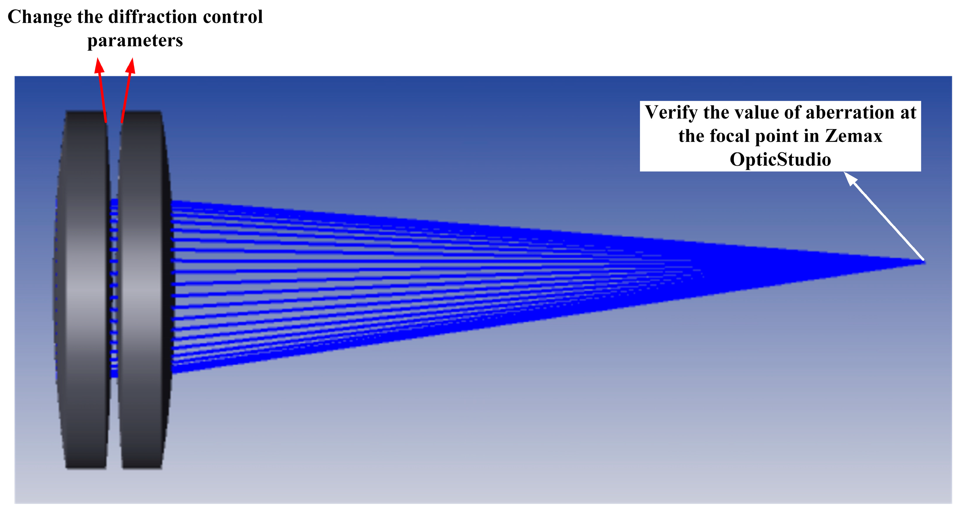
To eliminate the influence of other components in the system design, we only verify the aberrations of a single multilayer refractive–diffractive diffraction optical element (PMMA and PC, the view angle is 12°, additional diopter is 2D). Verification was carried out through Zemax OpticStudio 2019. Since there is no corresponding broadband refractive–diffractive aberration design model for comparison, we designed three control experiments ourselves. The three design results are compared: the traditional multilayer diffraction optical element (Design A), the corrected multilayer diffraction optical element designed only by Equation (10) (Design B), and the multilayer diffraction optical element designed through the PIA model (Design C). Among them, Design B is designed only by Equation (10), which aims to make the spherical aberration 0 at the design wavelength of 555 nm. Design C achieves stable imaging in the broadband of 450–700 nm. The refraction part parameters of Design A, Design B, and Design C are designed exactly the same.
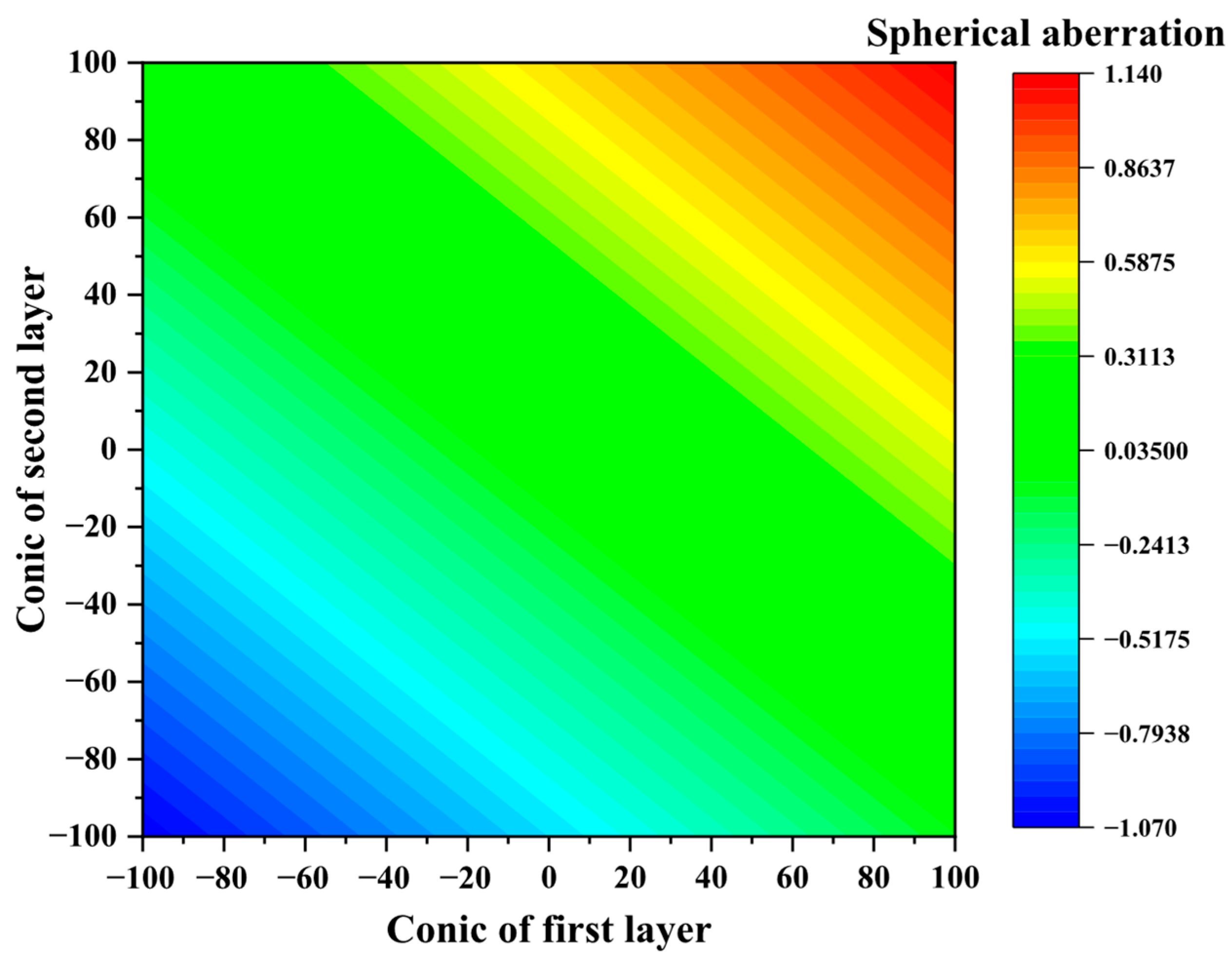
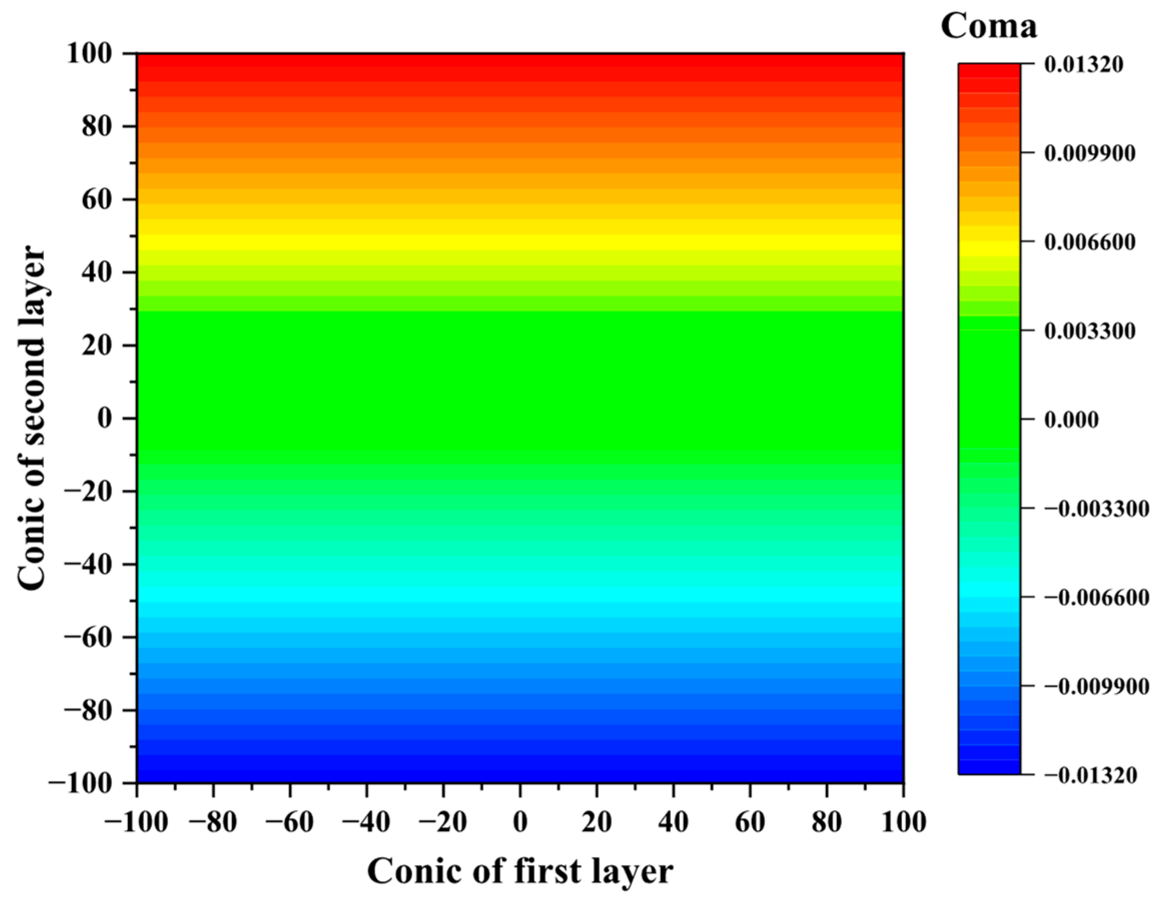
First, the initial structure is presented to obtain the initial design by making the coma equal to 0 for Designs A and B. For the initial curvature, we randomly adopt a structure to prove the universality of our model. At this time, R f 1 = 20   mm , R s 1 = 40   mm , R s 2 = 40   mm , R b 2 = 20   mm , the thickness is set as 1 mm for each layer, and h1 and h2 are set as 3 mm. Next, the aspheric control parameter is added to make the coma equal to 0 at design wavelength 550 nm (shown in Figure 3 and Figure 4). As can be seen from Equation (10), the conic coefficient and the fourth-order aspheric coefficient have the same effect. Therefore, we did not add the fourth-order aspheric coefficients and only regulated the conic coefficients. The conic coefficient design results are Q f 1 = 7.17501 and Q b 2 = 5 . 54092 . Finally, all the data are verified by Zemax OpticStudio. The results are shown in Table 1 (To simplify the system, only the surfaces without diffraction structures are added, that is, the front surface of the first layer and the back surface of the second layer. From Figure 3 and Figure 4, it is indeed sufficient to complete the design requirement by adding only two surface conic parameters). This experimental design method, which involves using the control variable approach to compare the effects of different aberration optimization strategies separately, is a classic paradigm for evaluating the performance of optical systems. Design A is set as the benchmark, representing the basic MLDOE performance without aberration optimization, and its aberration performance will serve as the reference point for subsequent optimizations. Design B represents the traditional strategy of aberration correction for a single wavelength. Design C, as the core innovation of this study, demonstrates the superiority of the PIA method in balancing aberrations over a wide bandwidth. Simulation verification using Zemax OpticStudio software ensures the reliability of the experimental results. The random selection of initial parameters and the decision to only adjust the conical surface coefficients reflect the universality of the model and the simplification of analysis, avoiding the risk of overfitting to specific parameters. Setting the coma aberration to zero as the initial optimization objective enables a clearer observation of the effects of different methods on the spherical aberration and its broadband characteristics in the subsequent spherical aberration optimization process. Figure 3 clearly shows the trend of spherical aberration changing with the adjustment of the conic. From the figure, it can be seen that there are one or more specific conics that can minimize the spherical aberration, even approaching zero. This curve relationship provides designers with intuitive guidance, enabling them to effectively control the spherical aberration by adjusting the conic in actual design.
Similar to Figure 3, Figure 4 depicts the relationship between the coma aberration and conic. It is worth noting that although the conic is mainly used to correct spherical aberration, it also has a certain impact on coma aberration. However, as can be observed from Figure 4, the sensitivity of coma aberration to the conic may be different from that of spherical aberration, or its change trend may be relatively gentle within a certain range. This suggests that in the optimization process, we need to comprehensively consider the response of different aberrations to the same design parameter to achieve overall balance.
The data in Table 1 represent the initial optimization results. The aim was to correct the coma to zero by adjusting the conic and record the spherical aberration at that time. From the table, it can be seen that the spherical aberration calculated by our proposed model (−0.011 mm) is very close to the spherical aberration verified by Zemax OpticStudio (−0.010 mm), indicating that our theoretical model has high accuracy in predicting aberrations. At the same time, the coma in both the model and the verification reached 0 mm, confirming that adjusting the conic can effectively eliminate the coma. This result lays the foundation for subsequent broadband optimization, ensuring the basic imaging quality of the system along the axis and within a certain field of view.
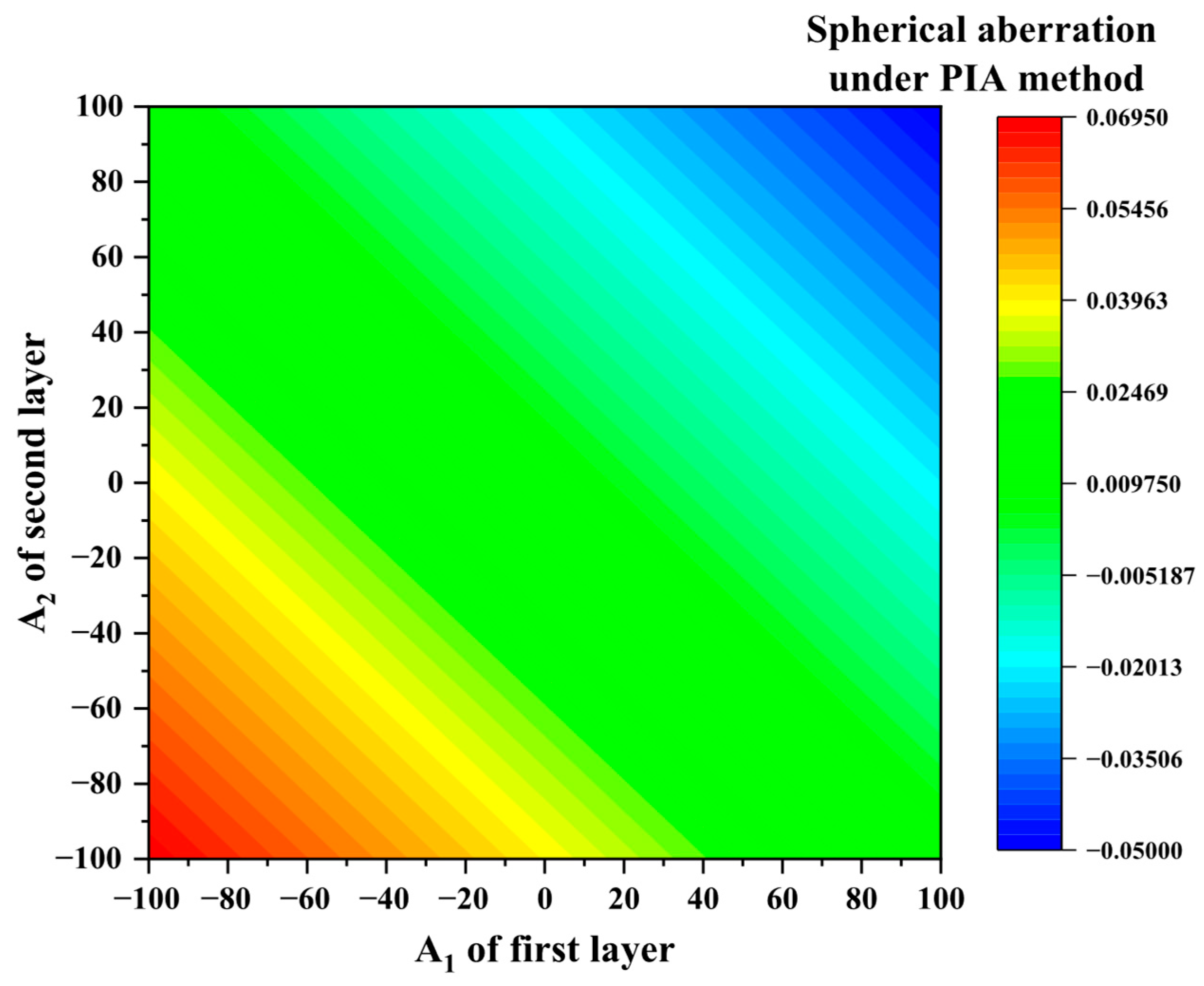
Then, through the regulation of diffraction control parameters A1 and A2, the ideal spherical aberration design aim is obtained (i.e., A1 and A2 = 0 for Design A; using Equation (10) to solve for Design B; and using the PIA method—Equation (11) for Design C, shown in Figure 5). The detailed parameters are shown in Table 2 (normalization value). The verification optical path is shown in Figure 6.
Figure 5 further discusses the influence of the diffraction control parameters A1 and A2 on spherical aberration. Similar to Figure 3 and Figure 4, the figure shows the curve of spherical aberration changing with the diffraction control parameters. By establishing the relationship between A1, A2, and aberration, we can easily obtain the combination of A1 and A2 for the condition of the aberration design requirement. It can be foreseen that by precisely adjusting these parameters, effective correction of spherical aberration can also be achieved. For the initial structure of this paper, we have completely corrected the coma. Then, by adjusting A1 and A2, we try to select values that can make the PIA = 0 in Figure 5 to minimize spherical aberration in the broadband. This figure is crucial for understanding the role of the diffraction structure in aberration correction, revealing the influence of the diffraction phase distribution on the imaging quality along the system axis. By combining Figure 3, Figure 4 and Figure 5, it is possible to more flexibly choose to correct aberrations through aspheric parameters of the refractive surface, optimization of the diffraction structure, or a combination of both to achieve the best performance.
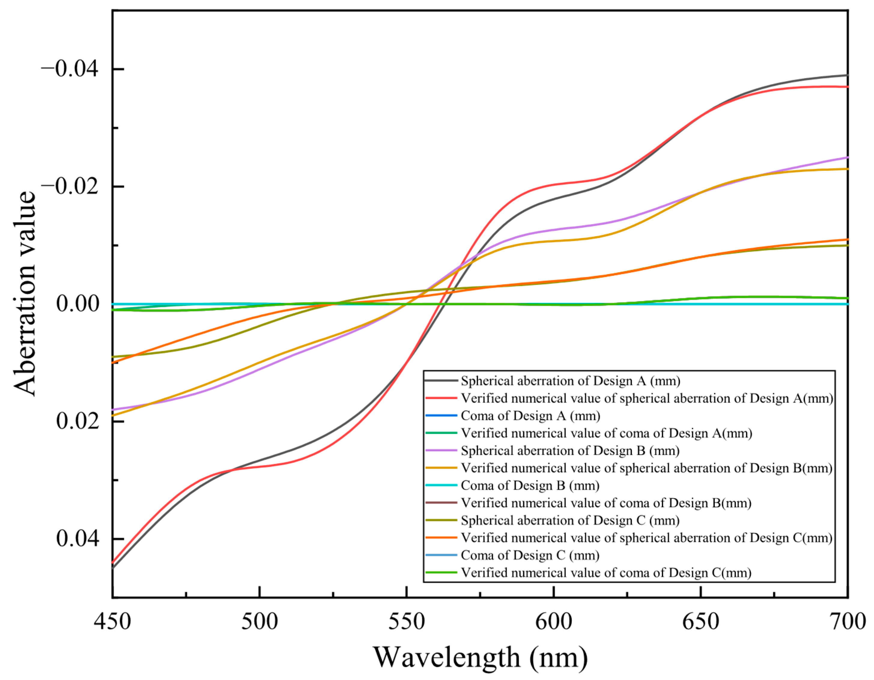
Figure 7 presents the core experimental results of this study. It visually compares the performance of the three design schemes in terms of spherical aberration and coma at different wavelengths. It should be noted that the three designs presented in this paper are only used to verify our proposed theory and therefore do not include subsequent tolerance analysis of the system. However, if the theory is to be applied in practice, sensitivity or tolerance analysis of the system is indispensable.
For the coma part, the coma curves of the three design schemes in the figure (including the verification values) are almost completely overlapping, and they remain at a level close to zero. This strongly validates the theoretical derivation of this study—the influence of the diffraction control parameters A1 and A2 on coma is negligible. This discovery is crucial because it means that when optimizing spherical aberration, we can independently adjust these diffraction parameters without worrying about a significant negative impact on coma, thereby greatly simplifying the complexity of the multi-objective optimization process.
For the spherical aberration part, the comparison of the three curves reveals the advantages and disadvantages of different aberration optimization strategies:
Design A (traditional multilayer diffractive optical element) has a highly fluctuating spherical aberration curve throughout the entire wavelength range, with large numerical values. This indicates that without performing aberration optimization, the system’s broadband imaging quality is unacceptable. The high spherical aberration value is the main reason for image blurring and resolution degradation.
Design B (single-wavelength optimization) has its spherical aberration corrected to an extremely low level at the design wavelength of 555 nm, almost zero. This proves the effectiveness of single-wavelength optimization through Equation (10). However, once deviated from 555 nm, the spherical aberration deteriorates rapidly, especially at the ends of the wavelength band, and its value even exceeds that of Design A. This “sacrificing the global for local optimization” strategy makes the system perform well only at specific wavelengths and shows significant limitations in broadband applications. For example, in color imaging, this will result in inconsistent focusing positions for different color channels, causing color edges or blurring.
Design C (PIA method optimization) has a spherical aberration curve throughout the 450–700 nm wavelength range; although it does not reach the extreme zero point at 555 nm as in Design B, its spherical aberration values remain at a relatively low and stable level. This means that through the PIA method, the system achieves “balanced correction” of aberrations throughout the broadband range. Although it may not be the absolute best in a single wavelength, it shows good performance across all wavelengths and avoids the drastic deterioration at non-design wavelengths like Design B. This balance is crucial for broadband imaging systems, ensuring clear and consistent image quality throughout the working wavelength range.
Overall, from Figure 7 (the lines of coma of Design A (mm), verified numerical value of coma of Design A (mm), coma of Design B (mm), verified numerical value of coma of Design B (mm), coma of Design C (mm), verified numerical values of coma of Design C (mm) almost coincide), first, it can be seen from the result that adding the parameters A1 and A2 has almost no effect on the coma. This also verifies our derivation. Then, it also can be found that Design A cannot fully correct both spherical aberration and coma aberration simultaneously. Design B can satisfy the correction of spherical aberration and coma at the central wavelength, but it decreases significantly throughout the entire band and cannot meet the imaging effect in the broadband. Although Design C sacrifices a certain amount of imaging quality at the central wavelength, it still retains a part of the spherical aberration. However, through the PIA design, the control of spherical aberration and coma throughout the whole waveband has been achieved, thereby realizing high imaging quality throughout the whole waveband. In conclusion, we have demonstrated the effectiveness of the PIA design, The method can be widely applied in the design of all multilayer refractive–diffractive optical systems.
Finally, we discussed the manufacturability of the method. The manufacturing shielding effect will affect the diffraction efficiency. Therefore, we need to ensure that the period width of the designed diffraction optical element is not too small. Since the additional optical power of the diffraction optical element described in this paper is very low, according to r j = 2 λ j 1 ϕ where ϕ is the additional optical power and rj is the period radius, its period radius (corresponding to the period width) is also relatively small. Thus, it will not cause excessive manufacturing shielding errors. Since the step height of the designed MLDOE is still at the micrometer level, for single-point diamond turning, the height error can be basically ignored.

5. Conclusions

Multilayer refractive–diffractive optical elements are widely used in imaging systems. In this paper, the aberration system of multilayer refractive–diffractive optical elements is derived in detail. Based on this, an evaluation method for the imaging quality of multilayer refractive–diffractive optical elements is proposed in the broadband. As the most common multilayer diffractive optical element, this paper presents the design of the double-layer diffractive optical element. Furthermore, the theory in this paper is also applicable to the design of multilayer diffractive optical elements with three or more layers. However, at this point, there are not only A1 and A2, but also parameters such as A1, A2, A3 …, to regulate. On the other hand, the aberration method presented in this paper is still applicable to subsequent analyses, such as those of wide fields of view. However, at this point, the PIA evaluation equation also needs to be integrated over the field of view, which will be studied in future work. Furthermore, the proposed lenses can be easily manufactured using methods such as single-point diamond lathes. Adding the fourth-order aspheric coefficient does not cause additional difficulties in the manufacturing process. This indicates that our method can be widely utilized.
It should be noted again that the method proposed in this paper can not only design broadband aberration-eliminating multilayer refractive–diffractive optical elements but also can use multilayer diffraction optical elements if the system needs to correct the corresponding aberrations. Correspondingly, if the imaging quality of the system is poor in a certain waveband, further improving the proposed PIA model by increasing the weight of the waveband will also be one of the future research directions.
In this paper, we only achieved the correction of spherical aberration and chromatic aberration. Of course, since this paper provides the derivation of five types of aberrations, it is impossible to fully achieve the simultaneous correction of all five types of aberrations. This would require more complex derivations and might need to rely on algorithms. Furthermore, since nano- or micrometer-sized metasurfaces can also be regarded as thin lenses, based on the theory proposed in this paper, it is of great significance to further derive an aberration system applicable to metasurfaces.
In conclusion, the establishment of the model fills the gap in the research on the imaging quality of broadband multilayer refractive–diffractive optical elements in visible light wideband and infrared broadband systems. Introducing multilayer diffractive optical elements into the traditional system not only cannot correct the aberrations of the system but will instead introduce additional aberrations, thereby affecting the imaging quality. However, through our research, not only can a multilayer diffractive optical element be used to achieve the design goals of thinness and broadband, but also the imaging quality of the system can be corrected.
Then, when applying the multilayer refractive–diffractive optical system designed based on this principle, it is very necessary to conduct a tolerance analysis on the system. Further combined with the study of its diffraction efficiency, a multilayer refractive–diffractive optical system with both high diffraction efficiency and high imaging quality will be obtained.

Author Contributions

Y.Y.: Conceptualization; Data curation; Formal analysis; Methodology; Software; Validation; Roles/Writing—original draft; and Writing—review and editing. C.L.: Methodology; Software; W.Y.: Data curation; Y.W.: Formal analysis; Methodology; M.L.: Formal analysis; Software; B.D.: Conceptualization; Formal analysis; Roles/Writing—original draft; and Writing—review and editing. C.X.: Conceptualization; Funding acquisition; Project administration; Supervision; Resources. All authors have read and agreed to the published version of the manuscript.

Funding

This work was supported by Natural Science Foundation of Jilin Province (YDZJ202501ZYTS651).

Data Availability Statement

All the data used have been shown in this paper.

Conflicts of Interest

The authors declare that there are no conflicts of interest related to the work.

Appendix A. The Primary Aberration Expressions Which Can Be Found from Ref. [15] and Our Previous Published Ref. [16]

The refractive aberration has been discussed in Ref [15] or our previously published Ref. [16].
The curvature of the refractive lens will affect the aberration. The shape factor is defined as
X = c 1 + c 2 c 1 c 2 ,
The location of the refractive lens will also affect the aberration. The position factor is defined as
Y = n u + n u n u n u
Then, the Lagrange invariant can be expressed as
H = n θ h = n θ h
So, the refractive part spherical aberration of the n layer is expressed as
S I , R n = 1 8 h n 4 K n 3 a 1 n X n 3 + a 2 n Y n 3 + a 3 n X n 2 Y n + a 4 n X n Y n 2 + a 5 n X n 2 + a 6 n Y n 2 + a 7 n X n Y n + a 8 n X n + a 9 n Y n + a 10 n
where
a 1 n = 1 μ 2 n 2 ( μ n ) 2 n 2 μ n 2 a 2 n = 1 μ μ 2 n 2 n 2 μ 2 n 2 n 2 a 3 n = 1 μ 2 μ + 3 n μ n μ + 3 n μ n a 4 n = 1 μ 2 2 μ + 3 n n 2 μ + 3 n n a 5 n = 1 μ μ + 2 n ( μ n ) 2 + μ + 2 n μ n 2 a 6 n = 1 μ 3 μ + 2 n n 2 + 3 μ + 2 n n 2 a 7 n = 4 μ μ + n n ( μ n ) + μ + n n μ n a 8 n = 2 μ + n n ( μ n ) 2 2 μ + n n μ n 2 a 9 n = 3 μ + n n 2 ( μ n ) 3 μ + n n 2 μ n a 10 n = μ 2 1 n 2 ( μ n ) 2 + 1 n 2 μ n 2 .
For the MLDOE, µ is expressed as n1 for the first layer, µ is expressed as n2 for the second layer, and n and n′ are the refractive indices of air, expressed as 1.
The refractive coma part of the n layer is expressed as
S I I , R n = 1 4 h n 2 K n 2 H n p 1 n X n 2 + p 2 n Y n 2 + p 3 n X n Y n + p 4 n X n + p 5 n Y n + p 6 n ,
where
p 1 n = 1 μ 2 n μ n n μ n p 2 n = 1 μ 2 μ 2 n 2 n 2 μ 2 n 2 n 2 p 3 n = 1 μ 2 μ + 2 n n μ + 2 n n p 4 n = 1 μ μ + n n ( μ n ) + μ + n n μ n p 5 n = 1 μ 2 μ + n n 2 + 2 μ + n n 2 p 6 n = μ 1 n 2 ( μ n ) 1 n 2 μ n .
The refractive parts of astigmatism, curvature, and distortion of the n layer are expressed as
S I I I , R n = 1 2 H n 2 K n 1 n 2 + 1 n 2 1 n 2 1 n 2 Y n S I V , R n = H n 2 K n 2 μ 1 n + 1 n + 1 n 1 n X n S V , R n = H n 3 h n 2 1 n 2 1 n 2 .

References

  1. Hu, Z.Y.; Jiang, T.; Tian, Z.N.; Niu, L.G.; Mao, J.W.; Chen, Q.D.; Sun, H.B. Broad-Bandwidth Micro-Diffractive Optical Elements. Laser Photonics Rev. 2022, 16, 2270015. [Google Scholar] [CrossRef]
  2. Hu, Y.; Cui, Q.F.; Zhao, L.D.; Piao, M.X. PSF model for diffractive optical elements with improved imaging performance in dual-waveband infrared systems. Opt. Express 2018, 26, 26845–26857. [Google Scholar] [CrossRef] [PubMed]
  3. Mao, S.; Cui, Q.; Piao, M. Optimal design method on diffractive optical elements with antireflection coatings. Opt. Express 2017, 25, 11673–11678. [Google Scholar] [CrossRef] [PubMed]
  4. Piao, M.; Cui, Q.; Zhao, C.; Zhang, B.; Mao, S.; Zhao, Y.; Zhao, L. Substrate material selection method for multilayer diffractive optics in a wide environmental temperature range. Appl. Opt. 2017, 56, 2826–2833. [Google Scholar] [CrossRef] [PubMed]
  5. Kanclerz, P.; Toto, F.; Grzybowski, A.; Alio, J.L. Extended Depth-of-Field Intraocular Lenses: An Update. Asia-Pac. J. Ophthalmol. 2020, 9, 194–202. [Google Scholar] [CrossRef] [PubMed]
  6. Mao, S.; Zhao, J.; He, D. Analytical and comprehensive optimization design for multilayer diffractive optical elements in infrared dual band. Opt. Commun. 2020, 472, 125831. [Google Scholar] [CrossRef]
  7. Mao, S.; Zhao, J. Design and analysis of a hybrid optical system containing a multilayer diffractive optical element with improved diffraction efficiency. Appl. Opt. 2020, 59, 5888–5895. [Google Scholar] [CrossRef] [PubMed]
  8. Mao, S.; Zhao, L.; Zhao, J. Integral diffraction efficiency model for multilayer diffractive optical elements with wide angles of incidence in case of polychromatic light. Opt. Express 2019, 27, 21497–21507. [Google Scholar] [CrossRef] [PubMed]
  9. Zhang, B.; Cui, Q.; Piao, M.; Hu, Y. Design of dual-band infrared zoom lens with multilayer diffractive optical elements. Appl. Opt. 2019, 58, 2058–2067. [Google Scholar] [CrossRef] [PubMed]
  10. Valle, P.J.; Oti, J.E.; Canales, V.F.; Cagigal, M.P. Visual axial PSF of diffractive trifocal lenses. Opt. Express 2005, 13, 2782–2792. [Google Scholar] [CrossRef] [PubMed]
  11. Buralli, D.A.; Morris, G.M. Effects of diffraction efficiency on the modulation transfer function of diffractive lenses. Appl. Opt. 1992, 31, 4389–4396. [Google Scholar] [CrossRef] [PubMed]
  12. Yang, H.; Xue, C.; Li, C.; Wang, J. Optimal design of multilayer diffractive optical elements with effective area method. Appl. Opt. 2016, 55, 1675–1682. [Google Scholar] [CrossRef] [PubMed]
  13. Chassagne, B.; Canioni, L. Analytical solution of a personalized intraocular lens design for the correction of spherical aberration and coma of a pseudophakic eye. Biomed. Opt. Express 2020, 11, 850–866. [Google Scholar] [CrossRef] [PubMed]
  14. Chassagne, B.; Canioni, L. Individual design of aberration-free intraocular lenses. J. Opt. Soc. Am. A 2021, 38, 683–689. [Google Scholar] [CrossRef] [PubMed]
  15. Hazra, L.N.; Delisle, C.A. Primary aberrations of a thin lens with different object and image space media. J. Opt. Soc. Am. A 1998, 15, 945–953. [Google Scholar] [CrossRef]
  16. Dong, B.; Yang, Y.; Xue, C. Theoretical principle and design of high-imaging-quality refractive-diffractive optical elements by multifocal-simultaneous aberration-correction method. Results Phys. 2024, 59, 107570. [Google Scholar] [CrossRef]
Figure 1. Light path through (a) refractive optical lenses and (b) diffractive optical elements (can be regarded as thin lenses with an infinite refractive index).
Photonics 12 00690 g001
Figure 2. Model of multilayer refractive–diffractive optical elements.
Photonics 12 00690 g002
Figure 3. The relationship between spherical aberration and the conic of each layer.
Photonics 12 00690 g003
Figure 4. The relationship between coma and the conic of each layer.
Photonics 12 00690 g004
Figure 5. The relationship between spherical aberration and the diffraction control parameter of each layer.
Photonics 12 00690 g005
Figure 6. The verification optical path.
Photonics 12 00690 g006
Figure 7. Aberration results of different designs.
Photonics 12 00690 g007
Table 1. Results with designed conic coefficients.
ParameterNumerical Value
Spherical aberration in proposed model (mm)−0.011
Verified numerical value of spherical aberration (mm)−0.010
Coma in proposed model (mm) 0
Verified numerical value of coma (mm)0
Table 2. Design parameters.
ParameterNumerical Value
Diffraction control parameters A1 of Design A0
Diffraction control parameters A2 of Design A0
Diffraction control parameters A1 of Design B81.452
Diffraction control parameters A2 of Design B−39.544
Diffraction control parameters A1 of Design C63.021
Diffraction control parameters A2 of Design C−20.011
Disclaimer/Publisher’s Note: The statements, opinions and data contained in all publications are solely those of the individual author(s) and contributor(s) and not of MDPI and/or the editor(s). MDPI and/or the editor(s) disclaim responsibility for any injury to people or property resulting from any ideas, methods, instructions or products referred to in the content.

