Article

Real-Time Depth Monitoring of Air-Film Cooling Holes in Turbine Blades via Coherent Imaging During Femtosecond Laser Machining

1
Sino-French Institute of Nuclear Engineering and Technology, Sun Yat-sen University, Zhuhai 519082, China
2
School of Physics, Xihua University, Chengdu 610039, China
*
Authors to whom correspondence should be addressed.
Photonics 2025, 12(7), 668; https://doi.org/10.3390/photonics12070668
Submission received: 28 March 2025 / Revised: 30 May 2025 / Accepted: 3 June 2025 / Published: 2 July 2025
(This article belongs to the Special Issue Advances in Laser Measurement)

Abstract

Given the exceptional capabilities of femtosecond laser processing in achieving high-precision ablation for air-film cooling hole fabrication on turbine blades, it is imperative to develop an advanced monitoring methodology that enables real-time feedback control to automatically terminate the laser upon complete penetration detection, thereby effectively preventing backside damage. To tackle this issue, a spectrum-domain coherent imaging technique has been developed. This innovative approach adapts the fundamental principle of fiber-based Michelson interferometry by integrating the air-film hole into a sample arm configuration. A broadband super-luminescent diode with a 830 nm central wavelength and a 26 nm spectral bandwidth serves as the coherence-optimized illumination source. An optimal normalized reflectivity of 0.2 is established to maintain stable interference fringe visibility throughout the drilling process. The system achieves a depth resolution of 11.7 μm through Fourier transform analysis of dynamic interference patterns. With customized optical path design specifically engineered for through-hole-drilling applications, the technique demonstrates exceptional sensitivity, maintaining detection capability even under ultralow reflectivity conditions (0.001%) at the hole bottom. Plasma generation during laser processing is investigated, with plasma density measurements providing optical thickness data for real-time compensation of depth measurement deviations. The demonstrated system represents an advancement in non-destructive in-process monitoring for high-precision laser machining applications.

1. Introduction

Enhancing combustion chamber operating temperatures represents the most direct and effective approach to improving engine efficiency and thrust-to-weight ratio. This thermal intensification demands exceptional heat resistance from critical components exposed to combustion, particularly turbine blades. Strategically designed air-film cooling holes [1] enable these components to withstand extreme thermal loads while maintaining structural integrity and extended service life.
The advent of short-pulse laser drilling technology, facilitated by significant advancements in laser systems over recent decades, has emerged as a primary manufacturing solution for these precision cooling channels [2,3,4]. The superiority of femtosecond laser drilling has been experimentally demonstrated compared to other pulsed laser techniques (e.g., nanosecond and picosecond lasers) [5,6,7,8,9]. This stems from the characteristic timescale disparity between laser field–electron coupling and thermal conduction through metallic lattices, which fundamentally alters the energy transfer dynamics during laser–matter interaction. For a comprehensive overview of short-pulse laser–metal interactions spanning timescales from femtoseconds to milliseconds, please refer to the review paper [10].
In turbine blade drilling applications, optimizing both processing efficiency and hole quality represents critical objectives. High-fluence lasers have emerged as promising candidates for this purpose. The actual drilling performance in femtosecond laser processing is governed by multiple laser parameters, including fluence level and pulse duration [11,12,13]. Meanwhile, the resultant hole characteristics demonstrate significant dependencies on material properties [14,15] and geometric considerations, such as size effect [16].
As illustrated in Figure 1, the double-layer architecture of modern turbine blades necessitates precise depth control during laser processing. Premature termination of the laser pulse risks incomplete penetration, while delayed termination causes backside damage to the underlying substrate layer [17,18,19]. Current mitigation strategies involving interlayer fillers introduce secondary challenges, including post-processing removal complications and process complexity [17,19]. This underscores the critical need for real-time depth monitoring to achieve precise laser termination.
Optical imaging cameras are commonly integrated into drilling platforms for quality inspection [20]; however, their practical implementation reveals fundamental limitations. When plasma is induced through laser–material interaction, it will emit intense radiation that directly illuminates the camera’s photosensitive sensor array, causing sensor saturation or temporary malfunction. Consequently, optical monitoring can only be implemented during laser-off intervals in the pulsed operation cycle. This fundamental limitation inherently prevents the system from achieving true in-process monitoring or real-time detection capabilities during active laser machining processes.
Laser-Induced Breakdown Spectroscopy (LIBS) has demonstrated potential for depth monitoring in laser machining applications [21,22]. The technique operates by exciting target materials to plasma states using high-energy laser pulses, with subsequent spectral analysis of the emitted atomic emission lines. While enabling continuous in situ measurement capabilities, LIBS systems exhibit temporal resolutions on the microsecond scale—insufficient for real-time feedback control in femtosecond laser machining processes. Modified configurations employing femtosecond lasers as excitation sources [23] address this temporal limitation but introduce significant system complexity and operational costs.
Various interferometry-based systems [24] have been investigated for offline scanning applications, demonstrating significant utility in surface and near-surface characterization. Optical coherence tomography (OCT), employing a Michelson interferometer configuration, enables two-dimensional surface topography acquisition through either rotational scanning mirror movement or linear probe displacement in the sample arm. This technique has achieved remarkable success [25,26] in biomedical domains, including ophthalmology [27,28,29], intravascular imaging [30,31], and dental applications [32,33], while also inspiring cross-disciplinary innovations in fields such as coating evaluation [34] and industrial metrology [25,35].
In the realm of manufacturing process monitoring, Webster et al. pioneered inline coherent imaging (ICI) [36,37] for real-time drilling depth measurement, validating its potential through successful implementation in bovine bone experiments [38]. This technique has achieved rapid progress in laser welding [39,40,41,42], crack detection [43] and 3D printing [44] in recent years. Despite substantial advancements in femtosecond laser drilling technology over recent decades, particularly in precision machining of aerospace components, there remains a notable paucity of reported applications for similar techniques in monitoring double-layer engine blade drilling processes.
This study presents the first in situ real-time depth monitoring technique for femtosecond laser drilling of gas turbine engine blades, accompanied by preliminary experimental validation of the proposed methodology.

2. Materials and Methods

2.1. Diagnostics Methods
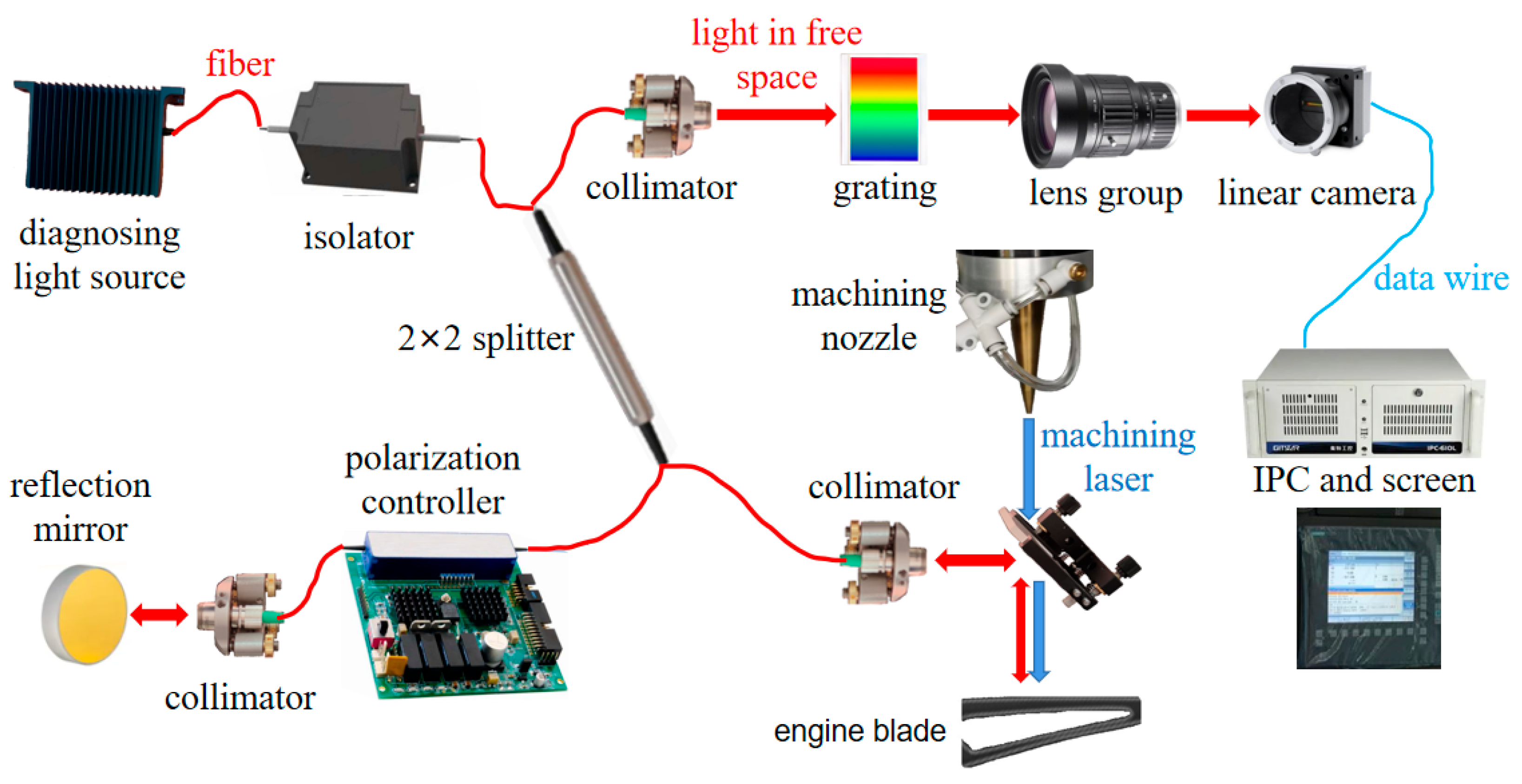
The core optical architecture of this real-time diagnostic platform, illustrated in Figure 2, features an enhanced spectral Michelson interferometer integrating a broadband coherent light source. It uniquely incorporates the femtosecond drilling laser path into the sample arm as an integrated optical component. The optical configuration employs a 2 × 2 fiber coupler with a 50:50 splitting ratio to interconnect the four essential interferometric components, namely, the coherent light source, reference arm, sample arm, and detection system.
The optical system design process begins with establishing the fundamental architecture of the light transmission pathway. Departing from conventional interferometer configurations that employ free-space optical elements for beam propagation, this implementation strategically utilizes fiber-optic components as the primary transmission medium. This critical design decision, the rationale for which will be comprehensively analyzed in subsequent sections.
A 12 mW super-luminescent diode (SLD, EXS210005-02; EXALOS, Schlieren, Switzerland) with a Gaussian-shaped emission spectrum centered at λ = 830   n m (Figure 3) and a full width at half maximum (FWHM) of Δ λ = 26   n m is selected as the coherent light source.
Upon exiting the fiber-coupled optical isolator, the light is coupled into the coupler where it splits into two equal-intensity beams. These separated beams propagate through the reference and sample arms, respectively. In the reference arm, the beam is retro-reflected by a stationary gold-coated reference mirror, maintaining a constant optical path length. A fiber-based polarization controller is integrated into this arm to ensure phase matching between the two interferometric paths.
The dichroic mirror serves as the core optical element in the sample arm assembly. This component performs critical beam combining functions by merging two orthogonally oriented laser paths: the horizontally propagating 830 nm diagnostic beam from the collimator and the vertically aligned 1030 nm machining beam emitted from the laser processing nozzle. Precise angular alignment is essential, requiring the mirror surface to be precisely aligned at a 45° incidence angle relative to both beam paths. The mirror’s specialized coating plays a vital role in system performance, engineered to achieve >99% reflectivity for the diagnostic wavelength (830 nm) while maintaining near 100% transmission efficiency for the machining wavelength (1030 nm). This spectral selectivity ensures optimal processing efficiency by minimizing power loss in the machining beam while preventing hazardous reflections of high-intensity laser radiation. Following beam combination, the superimposed optical paths are focused onto the target sample surface for synchronized diagnostic and processing operations.
The high-power laser beam performs material ablation to drill the hole (e.g., with a diameter of a submillimeter) in the sample, while the diagnostic beam undergoes partial reflection at the bottom surface of the hole. These reflected beams from both the reference arm and the sample arm subsequently converge at the beam splitter, where their coherent superposition generates measurable interference patterns.
The detection system employs a 38 × 38 mm volume phase grating with 1800 grooves/mm as its spectral dispersion element. Following this dispersion stage, a lens assembly focuses the spectrally resolved interference patterns onto a high-speed line scan camera (raL2048-48gm; Basler Electric Company, Highland, IL, USA) featuring 2000-pixel resolution. The acquired spectral data is then transmitted to an industrial-grade personal computing (IPC) platform for real-time analysis.
The experimental setup in this study employs a high-power femtosecond fiber laser system operating within a wavelength range of 1027–1040 nm and delivering sub-400 fs pulse durations. The laser source demonstrates a maximum single-pulse energy of 100 μJ, achieving a maximum output power of 20 W through frequency scaling. The processing beam undergoes dichroic mirror transmission before being focused by an optimized lens assembly. This collimated beam subsequently passes through a copper nozzle assembly, enabling precision drilling operations on engine blade components. The system’s ultrashort pulse characteristics ensure minimal heat-affected zones during the material ablation process.
The fiber-optic configuration demonstrates critical advantages for meeting both coherent optical requirements and industrial operational demands:
  • Adjustable path configuration:
    The fiber length can be precisely tuned to achieve an optimal optical path difference between interferometer arms, fulfilling the fundamental interference precondition.
  • Spectral filtering capability:
    During machining operations, plasma generation within the processing hole emits intense broadband radiation. Our system employs HI780 fiber (core diameter: 780 μm) for dual functionality: ① efficient transmission of the 830 nm probe beam; ② effective suppression of plasma emissions, back-reflected processing laser (1064 nm), and ambient light interference. This inherent filtering eliminates the need for darkroom conditions, significantly enhancing practical deployment feasibility.
  • Vibration immunity:
    The fiber architecture demonstrates exceptional mechanical decoupling, effectively isolating the interferometer from laser cooling system vibrations, workshop floor oscillations, and machining-induced mechanical disturbances.
  • Dynamic z-axis compatibility:
    The flexible fiber configuration enables seamless vertical synchronization between the machining head and sample arm collimator, maintaining optical alignment during depth progression without performance degradation.
This optimized design achieves minimal distortion while withstanding industrial vibrations, making it particularly suitable for in-process monitoring in laser drilling applications.

2.2. Physics for Algorithm

This coherent imaging diagnostic technique is employed to monitor the hole depth in real time during the drilling process. To enable closed-loop control of the machining laser through depth feedback, we have developed dedicated software capable of instantaneous depth calculation based on spectral interference principles. The algorithm’s core mechanism utilizes spectral interference pattern analysis, wherein the current study advances a coherent imaging methodology by accurately modeling the transient states of femtosecond laser drilling while building upon Mandel’s foundational theoretical framework [45].
The temporal evolution of light intensity can be obtained through the relation I t = V t V t , where the analytic signal V t is expressed as V t = 2 0 F T E t e x p 2 π i f t d f = A t e x p i Φ t 2 π i f ¯ t . Here, the asterisk * denotes complex conjugation, F T represents the Fourier transform operator, E t is the electric field, f denotes frequency, f ¯ is the mean frequency, and A t corresponds to the envelope of V t .
For interference analysis, the mutual coherence function between reference and sample beams is defined as Γ M Δ t = V R t V S t + Δ t , where   indicates ensemble averaging. The time delay Δ t = 2 z c originates from the optical path difference between the two arms, with z representing the hole depth causing the path difference, and c being the speed of light. The subscripts M , R , and S denote mutual coherence, the reference beam, and the sample beam, respectively.
The interferogram intensity can be mathematically expressed as
I i n t e r Δ t = V i n t e r t ; Δ t V i n t e r t ; Δ t = V S t + V R t + Δ t V S t + V R ( t + Δ t ) = I S t + I R t + 2 R e Γ M Δ t = I S t + I R t + 2 I S t I R t γ M Δ t c o s θ 0 2 π f ¯ Δ t
where θ 0 represents the initial phase (which can be conventionally set to zero) and γ M Δ t denotes the mutual coherence degree between the two beams. The coherence degree γ M Δ t plays a critical role in determining the interferogram quality.
The coherence condition depends on the relationship between the arm difference z and the coherence length ζ
  • When 2 z < ζ , γ M Δ t = 1 , as both beams originate from the same coherent source;
  • When 2 z > ζ , γ M Δ t = 0 , resulting in the disappearance of interference fringes.
In the drilling application context, the plasma generated during the process emits broadband radiation. While the collimator couples the 830 nm spectral component into the optical fiber, this plasma-originated light cannot interfere with the reference beam due to inherent incoherence—even at matching wavelengths. This incoherent component exhibits γ M Δ t = 0 , enabling effective isolation of the coherent light reflected from the hole bottom that carries crucial depth information. This coherence-based filtering mechanism ensures selective detection of the meaningful depth signal while rejecting plasma-induced background radiation.
In the experimental configuration described, a continuous-wave 12 mW laser diode serves as the illumination source. The collimated beam undergoes division through a 50:50 beam splitter, establishing the relationship I R = I S , B = 1 2 I D , where I S , B represents the optical intensity in the sample arm prior to interaction with the hole bottom, and I D denotes the total output intensity of the laser diode. The coherent light reflected from the bottom surface that successfully re-enters the sample arm exhibits an intensity of I S = η I S , B = 1 2 η I D , where η represents the perpendicular reflectivity at the hole bottom of the engine blade. This reflectivity parameter η plays a crucial role in the depth diagnostic methodology—the proposed technique becomes infeasible when η = 0 (indicating the complete absence of reflective capability at the hole bottom). While the alloy material of the engine blade inherently possesses substantial reflectivity, experimental observations suggest that only a small fraction of the reflected light ( 0 < η 1 ) can be effectively collected by the collimator. This significant signal attenuation primarily arises from surface irregularities at the hole bottom, induced during the drilling process, which creates a non-specular reflection surface that scatters most of the incident light away from the collection optics.
As previously described, femtosecond laser processing is employed to create holes in turbine blades. When a sequence of p laser pulses interacts with the metallic blade, it generates a corresponding set of hole depths z i i = 1 ~ p . Substituting these parameters into the interference Equation (1), the spectral interferogram intensities can be mathematically expressed as
I k , i = A k I D 2 p 1 + η + 2 η cos 2 k z i i = 1 ~ p ,
where k represents the wavenumber and A k denotes the spectral envelope of the light. The first term on the right-hand side constitutes a constant background signal that can be effectively distinguished through software algorithms. The second term, proportional to η (where 0 < η 1 ), becomes negligible due to its non-coherent nature and minimal magnitude. Experimental data presented in this study demonstrates that η remains relatively stable throughout the drilling process except during initial stages. Notably, even under significant η variations, this term remains dismissible as it lacks phase coherence. The third term represents the coherent interference component adhering to cosine modulation principles. Through analysis of this critical term, the complete set of hole depths z i i = 1 ~ p can be precisely determined.
For a Gaussian spectrum expressed as A k e x p k 2 / 2 σ 2 = e x p 4 l n 2 k / Δ k F W H M 2 , the product relationship Δ k F W H M Δ 2 z F W H M = 8 l n 2 can be derived through Fourier transform analysis, considering the wavevector relationship k = 2 π f . Here, σ represents the standard deviation, Δ k F W H M denotes the FWHM in k-space, and Δ 2 z F W H M = 2 Δ z F W H M corresponds to the FWHM in z-domain, where 2 z accounts for the round-trip path length variation in the sample arm. The depth resolution can be expressed in terms of the coherent wavelength Δ z F W H M = 2 l n 2 π λ ¯ 2 Δ λ F W H M 11.7 μ m , where λ ¯ = 830   n m represents the center wavelength, and Δ λ F W H M = 26   n m is the spectral FWHM of the coherent source light (as shown in Figure 3).

3. Results

3.1. Plasma Compensation

As discussed in the introduction section [7], femtosecond laser interaction with metallic materials generates plasma within the ablation hole during processing. While this plasma formation signifies the desired cold ablation mechanism that enhances machining efficiency and improves hole quality, its presence introduces significant challenges. The most critical issue arises when plasma fails to be promptly evacuated from the hole, leading to re-deposition of plasma-phase material on the inner wall and subsequent formation of a recast layer. This phenomenon becomes particularly problematic in deep-hole-drilling applications, where the accumulated recast layer can absorb energy from subsequent laser pulses, triggering renewed plasma generation within the hole. The resulting ‘plasma–recast layer–plasma’ cyclic interaction dramatically reduces processing efficiency during deep penetration drilling.
Although comprehensive plasma characterization could provide insights for mitigating this issue, such analysis extends beyond the scope of this study and will be addressed in future research. For the diagnostic methodology presented herein, the critical consideration lies in the plasma-induced optical path length deviation compared to atmospheric conditions. This optical modification is primarily governed by plasma density, which serves as the determining factor for the plasma’s optical thickness during laser–material interaction.
For sensitive coherent imaging diagnostics, plasma-induced variations in optical path length may become non-negligible, necessitating careful consideration of plasma correction mechanisms even when dealing with minimal plasma volumes. Figure 4 illustrates the experimental schematic for plasma density measurements during laser drilling processes. The machining laser employed in this study, consistent with the femtosecond fiber laser system detailed in Section 2, serves as the primary energy source for sample metal processing.
A metallic sample matching the engine blade material composition was pre-machined as illustrated in Figure 4. This specimen contains a pre-drilled 1 mm diameter cylindrical hole oriented perpendicular to the surface. A secondary coaxial aperture penetrates the sample laterally, creating an access port in the wall of the primary hole. A tungsten wire probe (radius r = 0.1   m m ) is inserted into this lateral channel, functioning as a Langmuir probe tip. Crucially, the probe tip is strategically positioned behind the aperture, shielded within the hole wall’s geometric shadow to prevent direct laser touching (indicated by blue dashed lines in Figure 4).
The probe connects to a scanning power supply, enabling real-time plasma density n e diagnosing [46,47] during drilling operations. Notably, while conventional Langmuir probes operate under vacuum conditions, our implementation addresses unique ambient atmospheric constraints requiring modified interpretation. To account for particle collision effects in the air, we employ a correction model, n e , m o d = 1 K n e , where the correction coefficient K is defined as K 1 1 2 1 1 + α 1 + 2 α 1 2 + α 2 1 + 2 α 1 2 1 + α . Here, α r ζ represents the ratio of probe radius r to the pressure-dependent mean free path ζ .
The dispersion relation governing electromagnetic wave propagation in plasma is expressed as ω 2 = c 2 k 2 + ω p e 2 , where ω p e = 4 π n e , m o d e 2 m e 1 2 represents the electron angular frequency, c denotes the speed of light in vacuum, and m e is the electron mass. The phase velocity of the wave is derived as v p = ω k = c 2 + ω p e 2 k 2 . Consequently, the plasma refractive index can be determined through the relationship R = c v p = 1 ω p e 2 ω 2 .
The measured plasma density within the hole represents a localized value of approximately 6.9 × 10²¹ m−3. Obtaining the vertical density profile proves challenging due to experimental constraints. Based on pressure equilibrium considerations within the hole, we adopt a uniform plasma distribution assumption for simplification. Incorporating all relevant constants and parameters into the governing equations yields the plasma-induced optical path length correction term Δk, as illustrated in Figure 5. This linear relationship can be mathematically expressed as Δk = 0.349d, where d denotes the instantaneous hole depth in millimeters and Δk is expressed in wavenumber units. This analysis reveals that when the hole depth reaches 1/0.349 ≈ 2.9 mm, the optical path discrepancy accumulates to one wavelength (830 nm).
For some deep vertical or inclined air-film holes in engine blades (e.g., 10 mm depth), the maximum measurement error induced by plasma effects reaches 2.9 μm. This magnitude is non-negligible compared to the system’s depth resolution ( Δ z F W H M 11.7 μ m ). In such cases, the plasma-induced error is significant and necessitates real-time compensation within the coherent imaging system’s depth measurement algorithm.

3.2. Real-Time Test Results

The diagnostic system was successfully integrated into the femtosecond laser drilling optical path with the experimental configuration illustrated in Figure 6a. Following laboratory validation, the system has been deployed on an industrial-grade laser drilling lathe (Figure 6b).
The sample arm configuration in the experiments is illustrated in Figure 7. Three colinear laser beams—represented by red (machining beam), purple (coherent diagnostic beam), and blue (reflected diagnostic beam) schematic lines—are shown spatially separated in the diagram for visual clarity, though they are actually coaxial in operation. Directional propagation of the diagnostic beams is indicated by purple and blue arrowed arc symbols.
A high-precision kinematic mirror mount system achieves critical alignment through three-axis positional adjustment of the dichroic mirror and two-axis angular alignment to maintain 45° incidence relative to the machining beam (denoted by black dotted line). Another mirror mount system is utilized to optimize the collimator for parallel beam output. The blade specimen (1 mm single-wall thickness) is secured on a five-axis positioning stage at the focal plane of the machining lens assembly.
The machining laser parameters corresponding to Figure 6a are summarized in Table 1. Laser rotary cutting is achieved using a two-axis laser superscan (Model SS-IIE-15, RAYLASE GmbH, Wessling, Germany) system, with the machining beam focused to approximately 0.05 mm through a telecentric lens (focal length f = 167 mm).
Prior to machining operations, the diagnostic system undergoes precise calibration, enabling the line-scan camera to capture clear and coherent interference fringe patterns as demonstrated in Figure 8a. In this schematic representation, the abscissa corresponds to the one-dimensional intensity distribution of interference fringes captured by the line-scan camera and the ordinate represents the temporal sequence of fringe patterns. The temporal interval between adjacent fringes is governed by the camera’s row acquisition frequency, F r = 51   k H z .
Upon activation of the machining laser, the interference fringes exhibit progressive displacement along the abscissa due to alterations in the sampling optical path, as illustrated in Figure 8b. To address this phenomenon, we have developed the Coherent-imaging for Hole drilling in Engine blades (CHE, Version 1.0) software platform. This specialized system performs dual functions: (1) real-time discrimination of interference patterns from background noise through advanced signal processing algorithms and (2) precise depth reconstruction of drilled holes based on quantitative analysis of fringe displacement.
It is crucial to emphasize that verifying the applicability of this diagnostic method constitutes a fundamental prerequisite prior to experimental implementation. Since depth variation is derived from fringe pattern evolution, the incremental depth change between consecutive fringe line images must remain below half the central wavelength. This constraint establishes the maximum permissible drilling speed as
V d r i l l < V m a x = 0.5 λ F r 21.2   μ m / s 1.27   m m / m i n u t e
To satisfy this condition while accounting for drilling speed variations across different depth regimes, the average drilling speed in our experiments was maintained at approximately 0.4   m m / m i n u t e .
Figure 8c presents representative time-series data of coherent imaging intensity captured by the CHE software. Consistent with the representations in Figure 8a,b, the abscissa denotes the partially magnified one-dimensional intensity profile of interference fringes, while the ordinate represents distinct temporal data sequences corresponding to different acquisition times during the drilling process. This panel specifically displays 7 out of 4500 recorded intensity profiles (sampled between 3500 and 8000 time units), through which the temporal variations in coherent image characteristics become visually evident. The progressive evolution of fringe patterns along the temporal axis demonstrates measurable changes in optical coherence properties during drilling operations.
Figure 9 illustrates the evolution of hole depth monitored by the real-time inline coherent imaging diagnostic system. In this experimental configuration, the super-luminescent diode in the diagnostic apparatus remains continuously operational while the line-scan camera is synchronized through the CHE control software. Following a stabilization period of several seconds after camera activation, the machining laser is initiated. The ablation process demonstrates progressive deepening of the hole over time, as evidenced by the continuously updated negative depth values measured through the diagnostic system and computed in real-time by the CHE platform.
The machining efficiency of the femtosecond laser can be quantitatively assessed by analyzing the absolute value of the slope derived from the depth progression curve. The termination of the drilling process is clearly indicated when the depth curve achieves stabilization: the slope asymptotically approaches zero while the depth measurement maintains a constant value of −1 mm, corresponding to penetration of the blade sample.
To obtain unambiguous evolution of interference fringes for precise hole depth extraction, the machined surface at the hole bottom must exhibit significant perpendicular reflectivity η to the 830 nm sampling light. Prior to drilling operations, η demonstrates substantial variability across the blade surface. Through precise alignment of the 5-axis platform securing the blade (as schematically illustrated in Figure 7), this reflectivity can be optimized to achieve its maximum value η m a x . This optimal alignment ensures spatial coincidence between the machining laser beam and the surface normal vector of the blade surface.
Upon laser activation, the initially smooth blade surface undergoes significant modification. A critical operational concern emerges regarding the potential loss of diagnostic beam reflection from the processed surface. This phenomenon may originate from multiple factors including (1) surface roughening induced by laser ablation and (2) formation of a recast layer during the drilling process. The severity of these effects relates fundamentally to the complex physics of femtosecond laser–material interactions and plasma dynamics within the confined hole geometry—phenomena that remain incompletely characterized in the current scientific understanding. While optimization of laser processing parameters and recast layer mitigation represent important research directions, these considerations fall beyond the scope of the present work, which focuses specifically on diagnostic methodology development.
Figure 10 presents the temporal evolution of normalized interference fringe intensity throughout the drilling process, referenced to pre-drilling baseline values. Immediate intensity reduction to approximately 45% of initial values occurs at laser activation ( t 16   s ), indicating rapid degradation of surface reflectivity. Notably, a sufficient signal persists for detection by our specialized analytical software. Crucially, the intensity maintains remarkable stability throughout subsequent drilling operations—a vital characteristic enabling continuous depth monitoring through fringe variance integration.
It should be emphasized that the intensity relationship follows I η as derived in Equation (2). Consequently, the normalized surface reflectivity during processing can be estimated as η η m a x 0.45 2 0.20 , based on the data presented in Figure 10.
Notably, in this machining context, surface reflectivity serves as the critical parameter determining the diagnostic efficacy of coherent imaging. Previous ICI experiments have demonstrated exceptional imaging performance when processing materials with high reflectivity, such as 304 stainless steel [37] and non-metallic substrates, including silicon [48], ceramics, bone, and wood [38]. However, hole drilling presents fundamentally different challenges compared to surface etching.
The inherent complexities of femtosecond drilling operations—characterized by irregular hole morphology and the inevitable formation of light-absorbent recast layers—can significantly degrade surface reflectivity. This reduction (quantified at ~0.20 in Figure 9) manifests as image degradation in coherent imaging, potentially leading to complete diagnostic failure in extreme cases. Figure 8b illustrates progressive image blurring during drilling operations, while Figure 11 presents a more severe scenario observed in aluminum alloy processing. The temporal image series reveals a faint negative-slope linear feature emerging at laser activation ( t 20   s ), representing time-resolved coherent images with critically low reflectance.
This reflectivity challenge imposes stringent requirements on CHE sensitivity. The diagnostic system demonstrates remarkable detection capability, maintaining image resolution even with sample reflectance as low as 0.1% of reference beam intensity. As illustrated in Figure 2, the conventional 50:50 beam splitter configuration can be optimized for low-reflectance applications. Implementing an asymmetric splitter (e.g., 1:99 ratio) enables real-time depth measurement in drilling operations with reflectivity levels down to 0.001%, significantly expanding the technique’s applicability to low-reflectance materials.

4. Discussion

The fiber-optic system serves as the primary medium for light beam transmission in the optical pathways. This configuration ensures a diagnostic system that is compact, flexible, practical, and robust. The fiber architecture effectively isolates interference fringe patterns from background light contamination. Furthermore, the fiber-optic design helps minimize vibrational impacts on both the optical path integrity and interference fringe stability—a critical advantage in large-scale processing workshops where mechanical vibrations are inherently unavoidable.
The system architecture employs strategically selected component models and parameters to ensure strict compliance with the operational specifications of the target engine blade model. The developed diagnostic system has been successfully implemented as a modular testing component within a femtosecond laser micromachining platform, specifically engineered for high-precision hole-drilling applications. Notably, the system’s architecture is designed with inherent scalability, permitting seamless adaptation to alternative operational scenarios through either modular replacement of core components or integration of supplementary functional modules.
The current diagnostic framework is specifically tailored for existing femtosecond laser drilling systems. Although laser drilling quality depends on various parameters (e.g., laser settings, hole parameters, and metal types) as discussed in the Introduction, these drilling parameters exhibit minimal influence on the real-time depth monitoring system for two fundamental reasons: (1) the processing laser and diagnostic laser operate incoherently, and (2) the diagnostic mechanism only requires the detection of partial reflection signals, which remains independent of geometric hole parameters such as diameter. From the perspective of backside damage prevention, measurement accuracy itself is not the primary concern—the critical function lies in detecting complete penetration through the abrupt disappearance of coherent interference patterns, thereby triggering automatic laser shutdown. Furthermore, this diagnostic approach demonstrates potential applicability to other laser machining processes, including those employing longer pulse durations. Notably, molten pool formation at the hole bottom during such operations may actually enhance diagnostic laser reflection efficiency.
However, when applied to next-generation drilling platforms with significantly enhanced processing speeds, Equation (3) becomes invalid. While this limitation can theoretically be addressed by implementing line-scan cameras with elevated row frequencies, such adaptation would substantially increase image data volume and potentially compromise real-time depth calculation capabilities.
In the blade hole-drilling diagnostic system, the blade metal exhibits a reflectivity of 0.2 η m a x 0.2 . This indicates that compared to the reference arm employing a total reflection mirror, the majority of light in the sampling arm cannot be effectively retro-reflected into the collimator. Nevertheless, the current diagnostic configuration demonstrates that the reflected light intensity remains sufficient for precise interference fringe analysis. For applications involving samples with even lower surface reflectivity, optimizing the beam splitter ratio in Figure 2 to 10:90 or 1:99 would significantly enhance system performance.
In industrial processing environments, the focal position of the lens assembly within the machining head undergoes manual vertical adjustment based on operational experience to maintain drilling efficiency during deep air-film hole fabrication. The collimator in the sampling arm features a synchronized movement mechanism with the machining head, a design facilitated by the integration of optical fiber components. This synchronized motion ensures continuous compliance of the optical path difference between reference and sampling arms with interference requirements throughout the drilling process.
The empirically determined optical path length adjustment must be input into the CHE software and incorporated into the depth calculation algorithm. While the current experimental demonstration utilizes a 1 mm thick blade specimen to validate system performance, this diagnostic methodology remains fully applicable for deep-hole-drilling applications requiring greater penetration depths.
Langmuir probe measurements confirmed the plasma existence and quantified its density. The plasma-induced optical thickness introduces an incremental increase in the sample arm length. In deep-hole-drilling applications, the progressive accumulation of plasma optical path length presents two critical challenges for coherent imaging diagnostics:
  • Depth measurement error:
    The accumulated measurement error in depth quantification reaches several micrometers—a magnitude comparable to the system’s 11.7 μm depth resolution. We implemented plasma compensation in the CHE software-derived depth calculations using experimentally determined plasma density values. While this correction assumes uniform plasma density distribution (a simplification requiring refinement), it can mitigate a great part of the measurement discrepancy
  • Motion-tracking degradation:
    The depth measurement error induces erroneous movement judgments of the machining head, as previously described. Such miscalculations may trigger inappropriate sample arm length adjustments. The resulting optical path mismatch between sample and reference arms may violate the fundamental coherence condition, causing immediate loss of imaging functionality.

5. Conclusions

A novel in situ diagnostic system utilizing coherent imaging technology has been developed for real-time depth measurement during femtosecond laser drilling processes. A specialized software package (CHE) enables real-time depth calculations through advanced pattern-matching algorithms. An SLD light source operating at an 830 nm center wavelength with a 26 nm FWHM ensures 11.7 μm depth resolution. This integrated system has demonstrated successful application in precision drilling of air-film cooling holes for engine blades. The real-time depth feedback shows particular promise for adaptive laser termination upon reaching the target depth to prevent backside damage in hollow blade structures.

Author Contributions

Conceptualization, Y.Y. and R.L.; methodology, Y.Y.; software, C.X.; validation, Y.Y. and C.X.; formal analysis, Y.Y. and C.X.; investigation, Y.Y. and C.X.; resources, Y.Y. and R.L.; data curation, Y.Y. and P.X.; writing—original draft preparation, Y.Y. and P.X.; writing—review and editing, Y.Y. and P.X.; visualization, Y.Y. and P.X.; supervision, Y.Y. and R.L.; project administration, Y.Y. and R.L.; funding acquisition, Y.Y. and R.L. All authors have read and agreed to the published version of the manuscript.

Funding

This research was funded by the National Key Research and Development Program of China, grant number 2022YFE03100002.

Institutional Review Board Statement

Not applicable.

Informed Consent Statement

Not applicable.

Data Availability Statement

The original contributions presented in this study are included in the article. Further inquiries can be directed to the corresponding author(s).

Conflicts of Interest

The authors declare no conflicts of interest. The funders had no role in the design of the study; in the collection, analyses, or interpretation of data; in the writing of the manuscript; or in the decision to publish the results.

Abbreviations

The following abbreviations are used in this manuscript:
OCTOptical Coherence Tomography
ICIInline Coherent Imaging
SLDSuper-Luminescent Diode
FWHMFull Width at Half Maximum
IPCIndustrial-grade Personal Computing
CHECoherent-imaging for Hole drilling in Engine blade

References

  1. Ashcom, J.B. The Role of Focusing in the Interaction of Femtosecond Laser Pulses with Transparent Materials; Cambridge University Press: Cambridge, UK, 2003. [Google Scholar]
  2. Schulz, W.; Eppelt, U.; Poprawe, R. Review on laser drilling I. Fundamentals, modeling, and simulation. J. Laser Appl. 2013, 25, 012006. [Google Scholar] [CrossRef]
  3. Jia, X.; Chen, Y.; Liu, L.; Wang, C.; Duan, J. Advances in laser drilling of structural ceramics. Nanomaterials 2022, 12, 230. [Google Scholar] [CrossRef] [PubMed]
  4. Calabrese, L.; Azzolini, M.; Bassi, F.; Gallus, E.; Bocchi, S.; Maccarini, G.; Pellegrini, G.; Ravasio, C. Micro-milling process of metals: A comparison between femtosecond laser and EDM techniques. J. Manuf. Mater. Proc. 2021, 5, 125. [Google Scholar] [CrossRef]
  5. Rethfeld, B.; Ivanov, D.S.; Garcia, M.E.; Anisimov, S.I. Modelling ultrafast laser ablation. J. Phys. D Appl. Phys. 2017, 50, 193001. [Google Scholar] [CrossRef]
  6. Zhigilei, L.V.; Lin, Z.; Ivanov, D.S. Atomistic modeling of short pulse laser ablabtion of metals: Connections between melting, spallation, and phase explosion. J. Phys. Chem. C 2009, 113, 11892–11906. [Google Scholar] [CrossRef]
  7. Smirnov, N.A.; Kudryashov, S.I.; Rudenko, A.A.; Zayarny, D.A.; Ionin, A.A. Pulsewidth and ambient medium effects during ultrashort-pulse laser ablation of silicon in air and water. Appl. Surf. Sci. 2021, 562, 150243. [Google Scholar] [CrossRef]
  8. Neuenschwander, B.; Jaeggi, B.; Schmid, M.; Hennig, G. Surface structuring with ultra-short laser pulses: Basics, limitations and needs for high throughput. Phys. Proc. 2014, 56, 1047–1058. [Google Scholar] [CrossRef]
  9. Lei, S.; Zhao, X.; Yu, X.; Hu, A.; Vukelic, S.; Jun, M.B.G.; Joe, H.; Yao, Y.L.; Shin, Y.C. Ultrafast laser applications in manufactruing processes: A state-of-the-art review. J. Manuf. Sci. Eng. 2020, 142, 031005. [Google Scholar]
  10. Li, X.; Guan, Y. Theoretical fundamentals of short pulse laser-metal interaction: A review. Nanotechnol. Precis. Eng. 2020, 3, 105–125. [Google Scholar] [CrossRef]
  11. Momma, C.; Chichkov, B.N.; Nolte, S.; von Alvensleben, F.; Tunnermann, A.; Welling, H.; Wellegehausen, B. Short-pulse laser ablation of solid targets. Opt. Commun. 1996, 129, 134–142. [Google Scholar] [CrossRef]
  12. Nolte, S.; Momma, C.; Hacobs, H.; Tunnermann, A. Ablation of metals by ultrashort laser pulses. J. Opt. Soc. Am. B 1997, 14, 2716–2722. [Google Scholar] [CrossRef]
  13. Sokolowski-Tinten, K.; von der Linde, D. Generation of dense electron-hole plasmas in silicon. Phys. Rev. B 2000, 61, 2643–2650. [Google Scholar] [CrossRef]
  14. Hu, Y.; Jiang, R.S.; Huang, C.X.; Chen, C.L.; Wang, S.J. Simulation and experimental study of femtosecong laser ablation mechanisms of NiCoCrAlY coating. Surf. Coat. Technol. 2024, 494, 131469. [Google Scholar] [CrossRef]
  15. Liu, S.; Zhang, Z.; Yang, Z.; Wang, C. Femtosecond laser-induced evolution of surface micro-structure in depth direction of nickel-based alloy. Appl. Sci. 2022, 12, 8464. [Google Scholar] [CrossRef]
  16. Li, M.; Wen, Z.; Wang, P.; Liu, Y.; Li, Z.; Yue, Z. Femtosecond laser high-quality drilling of film cooling holes in nickel-based single superalloy for turbine blades with a two-step helical drilling method. J. Mater. Proc. Technol. 2023, 312, 117827. [Google Scholar] [CrossRef]
  17. Randall, G.J.; Rhoades, L.J. Laser Back Wall Protection by Particulate Shading. U.S. Patent US20070175872A1, 2 August 2007. [Google Scholar]
  18. Cuttell, M. Method of Drilling Through a Wall of Hollow Component. U.S. Patent EP2567775, 7 March 2013. [Google Scholar]
  19. Knowles, M.R.H.; Kearsley, A.J.; Andrews, A.J.; Bell, A.I.; Rutterford, G.; Foster-Turner, G.J. Laser-drilling. U.S. Patent 6365871, 2 April 2002. [Google Scholar]
  20. Kreutz, E.W.; Trippe, L.; Walther, K.; Poprawe, R. Process Development and Control of Laser Drilled and Shaped Holes in Turbine Components. J. Laser Micro 2007, 2, 123–127. [Google Scholar] [CrossRef]
  21. Anabitarte, F.; Cobo, A.; Lopezhiguera, J.M. Laser-induced breakdown spectroscopy: Fundamentals, applications, and challenges. ISRN Spectrosc. 2014, 2012, 285240. [Google Scholar] [CrossRef]
  22. Cao, Z.T.; Jiang, L.; Wang, S.M.; Wang, M.M.; Liu, L.; Yang, F.; Lu, Y.F. Influence of electron dynamics on the enhancement of double-pulse femtosecond laser-induced breakdown spectroscopy of fused silica. Spectrochim. Acta Part B At. Spectrosc. 2018, 141, 63–69. [Google Scholar] [CrossRef]
  23. Xu, Z.; Jiang, L.; Wang, S.; Sun, J.; Zhan, J.; Zhu, W. An accurate interface detection of TBCs coated blades by double pulse femtosecond laser-induced breakdown spectroscopy. Spectrochim. Acta Part B At. Spectrosc. 2025, 224, 107088. [Google Scholar] [CrossRef]
  24. Temnov, V.V.; Tinten, K.S.; Zhou, P.; von Linde, D.D. Femtosecond time-resolved interferometric microscopy. Appl. Phys. A 2004, 78, 483. [Google Scholar] [CrossRef]
  25. Bouma, B.E.; Tearney, G.J. Handbook of Optical Coherence Tomography; Marcel Dekker: New York, NY, USA, 2002. [Google Scholar]
  26. Fercher, A.F.; Drexler, W.; Hitzenberger, C.K.; Lasser, T. Optical coherence tomography—Principles and applications. Rep. Prog. Phys. 2003, 66, 239–303. [Google Scholar] [CrossRef]
  27. Swanson, E.A.; Izatt, J.A.; Hee, M.R.; Huang, D.; Lin, C.P.; Schuman, J.S.; Puliafifito, C.A.; Fujimoto, J.G. In vivo retinal imaging by optical coherence tomography. Opt. Lett. 1993, 18, 1864–1866. [Google Scholar] [CrossRef] [PubMed]
  28. Bagayev, S.N.; Gelikonov, V.M.; Gelikonov, G.V.; Kargapoltsev, E.S.; Kuranov, R.V.; Razhev, A.M.; Tuchin, I.V.; Zhupikov, A.A. Optical coherence tomography for in situ monitoring of laser corneal ablation. J. Biomed. Opt. 2002, 7, 633–642. [Google Scholar] [CrossRef]
  29. Wojtkowski, M.; Leitgeb, R.; Kowalczyk, A.; Bajraszewski, T.; Fercher, A.F. In vivo human retinal imaging by Fourier domain optical coherence tomography. J. Biomed. Opt. 2002, 7, 457–463. [Google Scholar] [CrossRef] [PubMed]
  30. Tearney, G.J.; Bouma, B.E.; Boppart, S.A.; Golubovic, B.; Swanson, E.A.; Fujimoto, J.G. Rapid acquisition of in vivo biological images by use of optical coherence tomography. Opt. Lett. 1996, 21, 1408–1410. [Google Scholar] [CrossRef]
  31. Tearney, G.J.; Brezinski, M.E.; Bouma, B.E.; Boppart, S.A.; Pitris, C.; Southern, J.F.; Fujimoto, J.G. In vivo endoscopic optical biopsy with optical coherence tomography. Science 1997, 276, 2037–2039. [Google Scholar] [CrossRef]
  32. Colston, B.W.; Sathyam, U.S.; DaSilva, L.B.; Everett, M.J.; Stroeve, P.; Otis, L.L. Dental OCT. Opt Express 1998, 3, 230–238. [Google Scholar] [CrossRef]
  33. Amaechi, B.T.; Higham, S.M.; Podoleanu, A.G.; Rogers, J.A.; Jackson, D.A. Use of optical coherence tomography for assessment of dental caries: Quantitative procedure. J. Oral Rehabil. 2001, 28, 1092–1093. [Google Scholar] [CrossRef]
  34. Xu, F.; Pudavar, H.E.; Prasad, P.N. Confocal enhanced optical coherence tomography for nondestructive evaluation of paints and coatings. Opt. Lett. 1999, 24, 1808–1810. [Google Scholar] [CrossRef]
  35. Li, T.; Wang, A.; Murphy, K.; Claus, R. White-light scanning fiber Michelson interferometer for absolute position-distance measurement. Opt. Lett. 1995, 20, 785–787. [Google Scholar] [CrossRef]
  36. Webster, P.J.L.; Yu, J.X.Z.; Leung, B.Y.C.; Anderson, M.D.; Yang, V.X.D.; Fraser, J.M. In situ 24 kHz coherent imaging of morphology change in laser percussion drilling. Opt. Lett. 2010, 35, 646–648. [Google Scholar] [CrossRef]
  37. Webster, P.J.L.; Wright, L.G.; Mortimer, K.D.; Leung, B.Y.; Yu, J.X.Z.; Fraser, J.M. Automatic real-time guidance of laser machining with inline coherent imaging. J. Laser Appl. 2011, 23, 022001. [Google Scholar] [CrossRef]
  38. Webster, P.J.L.; Wright, L.G.; Ji, Y.; Galbraith, C.M.; Kinross, A.W.; van Vlack, C.; Fraser, J.M. Automatic laser welding and milling with in situ inline coherent imaging. Opt. Lett. 2014, 39, 6217–6220. [Google Scholar] [CrossRef] [PubMed]
  39. Sokolov, M.; Franciosa, P.; Botros, R.A.; Ceglarek, D. Keyhole mapping to enable closed-loop weld penetration depth control for remote laser welding of aluminum components using optical coherence tomography. J. Laser Appl. 2020, 32, 032004. [Google Scholar] [CrossRef]
  40. Fleming, T.G.; Clark, S.J.; Fan, X.; Fezzaa, K.; Lun, C.; Leung, A.; Lee, P.D.; Fraser, J.M. Synchrotron validation of niline coherent imaging for tracking laser keyhole depth. Addit. Manuf. 2023, 77, 103798. [Google Scholar]
  41. Hsu, L.W.; Salminen, A. Laser welding monitoring with multisensory data fusion: A brief review. Mater. Sci. Eng. 2023, 1296, 012014. [Google Scholar] [CrossRef]
  42. Boley, M.; Fetzer, F.; Weber, R.; Graf, T. Statistical evaluation method to determine the laser welding depth by optical coherence tomography. Opt. Lasers Eng. 2019, 119, 56–64. [Google Scholar] [CrossRef]
  43. Fleming, T.G.; Rees, D.T.; Marussi, S.; Connolley, T.; Atwood, R.C.; Jones, M.A.; Fraser, J.M.; Leung, C.L.; Lee, P.D. In situ correlative observation of humping-induced cracking in directed energy deposition of nickel-based superalloys. Addit. Manuf. 2023, 71, 103579. [Google Scholar] [CrossRef]
  44. Fleming, T.G.; Nestor, S.G.L.; Allen, T.R.; Boukhaled, M.A.; Smith, N.J.; Fraser, J.M. Tracking and controlling the morphology evolution of 3D powder-bed fusion using inline coherent imaging. Addit. Manuf. 2020, 32, 100978. [Google Scholar] [CrossRef]
  45. Mandel, L.; Wolf, E. Optical Coherence and Quantum Optics; Cambridge University Press: Cambridge, UK, 1995. [Google Scholar]
  46. Hutchinson, I.H. Principles of Plasma Diagnostics, 2nd ed.; Cambridge University Press: Cambridge, UK, 2002. [Google Scholar]
  47. Langmuir, I.; Mott-Smith, H. Studies of electric discharges in gases at low pressures. Gen. Electr. Rev. 1924, 27, 449–455. [Google Scholar]
  48. Yang, J. Inline Coherent Imaging Applied to Laser Micromachining; Queen’s University Press: Kingston, ON, Canada, 2014. [Google Scholar]
Figure 1. Schematic illustration of laser drilling in the trailing edge section of a turbine blade. Backside thermal damage is induced on the inner surface of the adjacent cooling channel wall when the machining laser beam penetrates through the upper layer during the process.
Photonics 12 00668 g001
Figure 2. Optical configuration of the coherence-based imaging diagnostic system for real-time depth measurement during femtosecond laser drilling. Red arrows indicate the propagation direction of the diagnostic laser, while blue arrows denote that of the processing laser.
Photonics 12 00668 g002
Figure 3. The measured spectrum of the super-luminescent diode by a standard spectrometer with a central wavelength of 830 nm and an FWHM of 26 nm.
Photonics 12 00668 g003
Figure 4. Experimental configuration for plasma density measurement during the laser drilling process. The probe tip is strategically positioned behind the lateral aperture and its position limit is denoted by a blue dashed line.
Photonics 12 00668 g004
Figure 5. Optical path length correction (in wavenumbers) versus hole depth (in millimeters).
Photonics 12 00668 g005
Figure 6. (a) The hole depth experimental setup in the laboratory. (b) The hole depth diagnostics system in the laser drilling lathe.
Photonics 12 00668 g006
Figure 7. Schematic diagram of the sample arm in the coherent imaging diagnostic system.
Photonics 12 00668 g007
Figure 8. Temporal evolution of interference fringe patterns: (a) observed prior to machining; (b) captured during active machining; (c) representative time-series data of coherent image intensity acquired using the CHE software.
Photonics 12 00668 g008
Figure 9. Real-time monitoring of femtosecond laser-induced hole depth progression through dynamic interference fringe analysis.
Photonics 12 00668 g009
Figure 10. Normalized light intensity of coherent optical imaging during femtosecond laser drilling.
Photonics 12 00668 g010
Figure 11. Raw coherent image series captured during the drilling process in an aluminum alloy sample.
Photonics 12 00668 g011
Table 1. Parameters of the machining laser.
ParametersUnitsModel: Y15-F04 (Guoshen Ltd., Shanghai, China)
Central wavelengthnm1027–1040
Pulse widthfs400
Repetitive frequencyKHz50–200
Polarization direction Horizontal polarization
Single pulse power (maximum)μJ100
Output power (maximum)W20@200K
Beam circularity%>85
Beam diametermm2.5 ± 0.2
Power stability%<3
Disclaimer/Publisher’s Note: The statements, opinions and data contained in all publications are solely those of the individual author(s) and contributor(s) and not of MDPI and/or the editor(s). MDPI and/or the editor(s) disclaim responsibility for any injury to people or property resulting from any ideas, methods, instructions or products referred to in the content.

