Review

Advances in and Applications of Microwave Photonics in Radar Systems: A Review

Faculty of Electrical Engineering, University of Ljubljana, Tržaška cesta 25, 1000 Ljubljana, Slovenia
*
Author to whom correspondence should be addressed.
Photonics 2025, 12(6), 529; https://doi.org/10.3390/photonics12060529
Submission received: 23 April 2025 / Revised: 12 May 2025 / Accepted: 22 May 2025 / Published: 23 May 2025
(This article belongs to the Special Issue Recent Advancement in Microwave Photonics)

Abstract

:
Modern radar systems frequently encounter constraints on bandwidth, transmission speed, and resolution, particularly within complex electromagnetic settings. Microwave photonics (MWP) provides solutions through the integration of photonic elements to improve radar’s functionalities. This review paper examines the question of how to improve radar performance by using MWP-based radar components for signal transmission, local oscillator signal generation, radar waveforming, optical beamforming networks, mixing, filtering, co-site interference suppression, real-time Fourier transformation, and analog-to-digital conversion. MWP radar systems achieve wider bandwidths, greater resistance to electromagnetic interference, and reduced phase noise, size, weight, and power consumption. Consequently, the integration of MWP into radar systems has the potential to increase the accuracy of these systems.

1. Introduction

Conventionally, radar systems have been built solely using electronic technologies. However, these systems face major challenges caused by limited bandwidth, slow transmission rates, and poor resolution, which limit their ability to accurately detect and identify objects in complex electromagnetic environments. To address these restrictions, novel approaches are required, and microwave photonics (MWP) appears to be a promising option. Utilizing the unique features of photonic technologies, MWP can provide significant improvements to radar’s performance.
An MWP-based radar system has several advantages over conventional electronic radar systems. It can achieve significantly larger bandwidths, resulting in enhanced resolution. This is useful for a number of applications, including identifying small objects and tracking fast-moving targets. Reduced phase noise is another benefit of using MWP. This means that it can generate more precise reference signals, which can then be used for radar waveform generation or synchronization in distributed radar systems. Additionally, MWP components are immune to electromagnetic interference (EMI). This is crucial for radar systems employed in areas with significant EMI, such as military or industrial settings. Finally, using MWP can result in radar systems that are smaller, lighter, and more power-efficient. This is crucial for numerous applications, including airborne or space-based radar systems.
This review paper examines essential MWP technologies relevant to radar applications, which includes signal transmission, local oscillator (LO) signal generation, radar waveforming, optical beamforming networks, mixing, filtering, co-site interference suppression, real-time Fourier transformation (RTFT), and analog-to-digital conversion (ADC). The paper seeks to highlight the essential role of MWP in addressing the constraints of conventional radar systems and enabling next-generation radar systems.

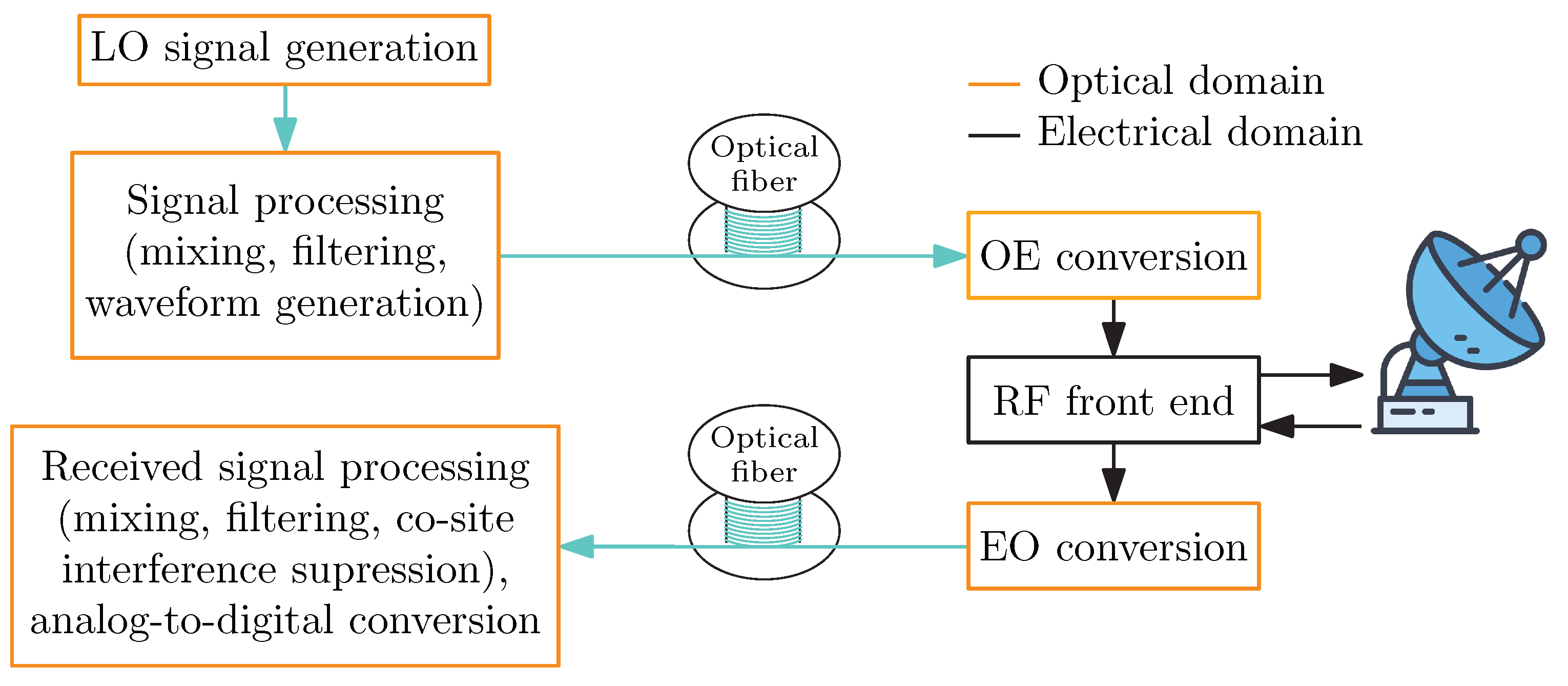
2. Microwave Photonics in Radar Systems

MWP is a multidisciplinary research field that merges two distinct areas: microwave or radio-frequency (RF) engineering and optoelectronics [1,2,3,4]. MWP offers several key advantages that are crucial to advancing new solutions in the generation, transmission, and processing of RF signals. These advantages include a wide and flexible bandwidth, low-phase noise components for signal generation and detection, immunity to EMI, and the utilization of efficient, scalable optical devices such as optical filters and lasers [5,6,7,8]. To take advantage of the photonic properties, broadband electrical-to-optical (EO) and optical-to-electrical (OE) conversions are introduced into radar systems. Figure 1 illustrates the architecture of a photonic radar system, where the RF signal is generated, processed, and transmitted to the antenna’s location in the optical domain. OE conversion occurs at the antenna location, which allows the signal to be transmitted by the antenna. After receiving the scattered signal, it is converted back to the optical domain via EO conversion for further processing and transmission in the optical domain.
Radar systems typically incorporate some form of analog signal processing, such as filtering, mixing, phase shifting, and time stretching, among others. These processes are essential for shaping, manipulating, and analyzing the radar signals to enhance performance and improve target detection and identification. Most of the mentioned operations can be easily implemented in the optical domain prior to OE conversion.
MWP-based radar systems provide improved spatial resolution, faster object detection, and reduced system size, weight, and power consumption. The spatial resolution of a radar system is given by
Δ r = c 2 B ,
where c is the speed of light in a vacuum and B is the bandwidth of the radiated radar signal [9]. As shown in Equation (1), the resolution is directly dependent on the signal bandwidth. Increasing the bandwidth of the radiated radar signal improves the spatial resolution, resulting in higher-resolution radar images. However, it is important to note that Equation (1) assumes ideal free-space propagation conditions, without accounting for practical factors such as atmospheric attenuation, scattering, or dispersion, which can become significant at higher frequencies. Therefore, while increasing bandwidth theoretically enhances resolution, the practical limitations imposed by environmental conditions must also be considered in system design and performance evaluations.
Another crucial factor to consider is the signal manipulation capability of radar systems, which is closely related to the relative bandwidth of these systems. The relative bandwidth is defined as the ratio between the radiated signal bandwidth and the central frequency [10]. Modern automotive radar systems typically operate at a central frequency of 77 GHz, with a bandwidth of approximately 4 GHz [11], yielding a relative bandwidth of about 5%.
In contrast, when implementing a radar system with the same 4 GHz bandwidth in the optical domain, where the central frequency is around 193 THz, the relative bandwidth decreases to approximately 0.002%. This substantial reduction indicates that a system considered broadband in the electrical domain becomes a very narrowband system in the optical domain. This characteristic offers greater flexibility for the design of radar systems and improved signal-manipulation capabilities.
Given that spatial resolution is dependent on both central frequency and bandwidth, radar systems are increasingly shifting toward higher frequency bands, such as the millimeter-wave (mmW, 30–100 GHz) band, the sub-terahertz (0.1–0.3 THz) band, and the terahertz (0.3–10 THz) band [12]. These higher central frequencies enable resolutions with sub-millimeter precision [13,14]. However, transmitting these high-frequency signals can be challenging and costly, requiring the use of optimal transmission media.

2.1. Signal Transmission

Signal transmission is widely utilized in radar systems, particularly in distributed radar networks, phased-array systems, and those requiring remote signal processing. The most commonly used media for signal distribution in radar systems are coaxial cables, waveguides, and optical fibers. Although coaxial cables are suitable for short distances and low frequencies, they become impractical for longer distances and higher frequencies due to high losses [15] and their cost. Nevertheless, their widespread availability makes them popular in modern radar applications. While waveguides are advantageous for high-power radar applications, they lack flexibility due to their rigidity. They are also costly for high-frequency applications and highly sensitive to mechanical vibrations, making them suitable only for permanent installations [16]. However, filling them with dielectrics can make them cheaper and more flexible. Polymer microwave fiber (PMF), a type of dielectric waveguide, has emerged as a promising technology for transferring microwave signals. PMFs are low-cost, highly temperature insensitive, lightweight, and mechanically robust [17]. Signals can be distributed with a PMF up to 25 m [18,19]. Optical fibers offer a viable alternative, offering key advantages such as lower losses, higher bandwidth, and immunity to EMI. This allows for the distribution of the signal over longer distances and the implementation of long optical delay lines, which can be used as high-quality optical storage elements in setups such as optoelectronic oscillators (OEOs). However, temperature fluctuations and mechanical vibrations cause delay fluctuations in the transmission of the signal through optical fibers, which can affect the phase of the received signal [20]. These delay fluctuations can be mitigated using various compensation methods designed to counteract these issues [21,22,23,24,25].
Compensation methods can be categorized into two groups: methods in which the phase of the transmitted signal is actively [22] or passively [23] adjusted and methods in which the phase is controlled by altering the physical properties of the transmission medium [24]. These properties include the fiber length and its refractive index. Additionally, compensation can be performed within the optical link by adjusting the laser wavelength [25]. Such methods enable phase-stable signal transmission, which is essential for achieving high spatial resolution in coherent distributed radar systems [26]. However, these techniques can be complex, costly to implement, and are not yet widely adopted in modern radar systems.
The use of optical fibers for transmitting RF signals is known as the Radio-over-Fiber (RoF). This technique offers several advantages, including low-attenuation broadband transmission, significantly reduced costs compared to those of other methods, the ability to transmit through multiple independent channels, and immunity from eavesdropping and EMI. Additionally, optical fibers are compact, flexible, and easy to install, making them particularly well suited to confined spaces, such as inside vehicles [27,28].
The transmission of multiple independent signals is essential in complex, modern radar systems. In distributed multiple-input multiple-output (MIMO) radar systems with coherent processing, it is necessary to distribute the LO signal, trigger signals for ADC synchronization, and large amounts of raw data. Independent, high-throughput, bidirectional signal transmission can be achieved using optical fibers with various multiplexing techniques, the most common being wavelength-division multiplexing (WDM), polarization-division multiplexing (PDM), space-division multiplexing (SDM), and mode-division multiplexing (MDM).
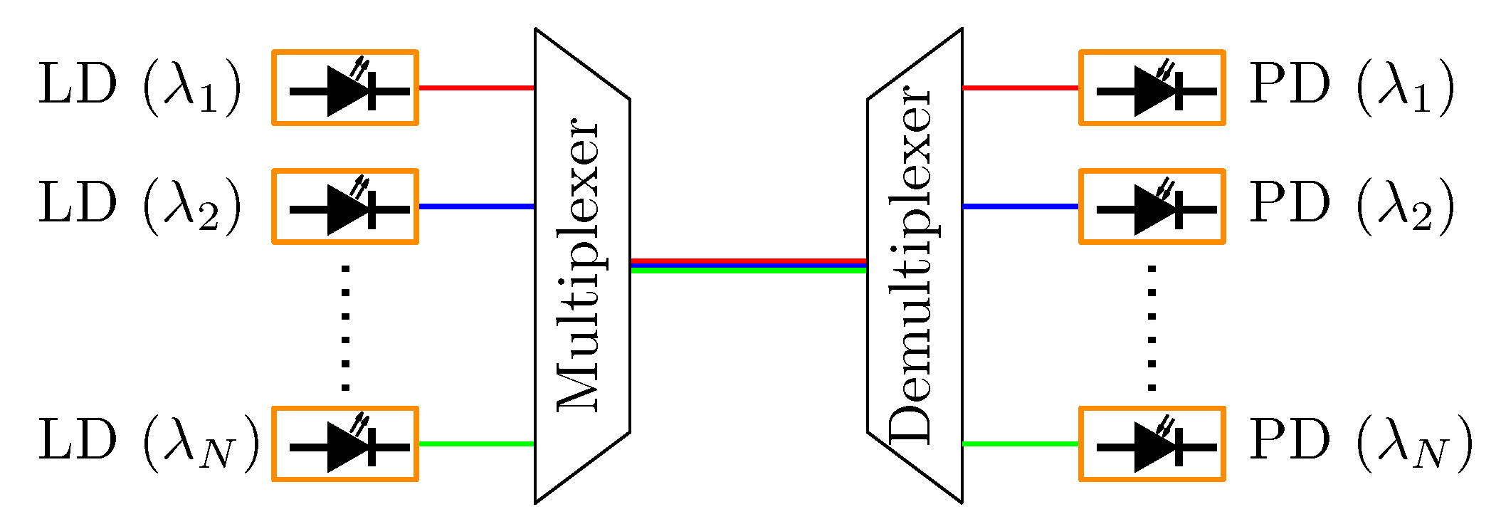
  • WDM enables the simultaneous transmission of multiple optical signals by assigning each signal a unique wavelength, allowing them to travel through a single optical fiber without interference [29]. This technique takes advantage of the large bandwidth available in optical fibers to significantly increase data capacity. Figure 2 illustrates a typical WDM system, which employs a multiplexer on the transmitter side to combine the input signals and a demultiplexer on the receiver side to separate them. Widely adopted in telecommunications, WDM improves fiber data throughput without requiring any additional physical infrastructure.
  • PDM is a technique that transmits two independent data channels on a single wavelength using orthogonal polarization states [30,31,32]. Although multiplexing two optical beams with orthogonal polarizations in an optical fiber is relatively straightforward, demultiplexing them can be challenging. This is due to the constant variation in the polarization states within single-mode fibers (SMFs), even though the polarizations remain orthogonal. Furthermore, polarization-maintaining fibers (PMFs) are limited to supporting a single polarization state, making them less suitable for PDM [33].
  • SDM employs multiple, spatially separate channels within a single optical fiber to enhance data transmission [34]. In the literature, different configurations that use multicore fiber (MCF) or multimode fiber (MMF) have been proposed as promising candidates for next-generation multiplexing technologies in optical fiber communications [35].
  • MDM is a multiplexing technique that uses different guided modes in a MMF for different transmission channels [36,37,38,39]. Typically, the MMFs used in such applications support a relatively small number of guided modes and are therefore referred to as few-mode fibers.
Combinations of various multiplexing techniques have also been extensively studied to maximize transmission performance. For example, in [40], hundreds of WDM channels were transmitted through more than 100 spatial channels, achieving an impressive transmission rate of 10.66 Pb/s. Similarly, different studies have demonstrated the use of combined techniques, such as PDM and WDM [41], MDM and WDM [42], and other multiplexing methods.

2.2. Local Oscillator Generation

LO signal generation is a crucial component of radar systems, providing reference signals for radar signal generation, synchronization, and timing for ADCs, digital-to-analog converters (DACs), and digital signal processing (DSP) modules. To meet the growing performance demands of modern radar systems, photonic techniques for LO generation have been proposed [8,43,44,45,46,47,48,49,50,51,52,53,54,55,56,57].
An important characteristic of an LO is its short-term frequency stability, also known as the phase noise. The low phase noise of the LO in a radar system is particularly crucial to accurately extracting weak reflections from targets. Another key characteristic is the spectral purity, which can be compromised by harmonics, sub-harmonics, and non-harmonic spurs generated by the LO. Traditionally, high-frequency LO signals are generated by multiplying the output of a low-frequency electrical oscillator, such as an oven-controlled crystal oscillator or a dielectric resonator. However, frequency multiplication in the electrical domain suffers from high phase noise, resulting from the multiplication factor, and a high spur level that require quality filtering to remove. Using photonic methods for LO generation in a radar system can significantly improve its performance, particularly in terms of phase noise, long-term frequency stability, spectral purity, complexity, and reliability. A comparison of various photonic LO-generation methods shows that techniques based on optical frequency multiplication [43,58,59,60,61], optical–microwave synchronization [44,45,46,62], and OEOs [47,48,49,50,51,52,53,54,55,56,57] achieve performances comparable to or better than their electronic counterparts.
The beating of two spectral lines can result in the generation of signals with a very low phase noise. One method is optical–microwave frequency multiplication, which works by using a low-frequency, narrow-band RF signal, generated in the electrical domain, to modulate a high-quality laser source via an MZM [58]. Figure 3 shows a typical optical frequency multiplier, which uses four MZMs to create a dual-band LMF radar signal. By adjusting the DC biases of the electro-optical modulator (EOM) or by incorporating an optical filter, specific sidebands can be selected. Sideband selection enables the generation of signals with frequencies that are two, four, or eight times or even higher multiples of the input RF frequency and is a key advantage of optical–microwave frequency multiplication. However, the quality of the generated signal is directly dependent on the quality of the input RF signal and its phase noise [59]. To improve the phase noise, mode-locked lasers (MLLs) can be used as the source for the spectral lines [60]. However, various imperfections and carrier fluctuations in the photodiode used in this process can increase the phase noise. A solution using an optical–microwave phase detector for optical–microwave synchronization was proposed to overcome the problem mentioned [45,46,62]. It works by converting optical pulses to an electrical signal using a photodiode and then using an optical–microwave phase detector to detect the phase difference between the microwave signal and the optical pulses [44]. Feedback is applied to the MLL or its repetition rate to achieve synchronization. Applying this method to an MLL can result in ultra-low-noise synchronization between the components, allowing for ultra-low-phase noise LO signal generation.
A promising solution for low-noise LO generation is an OEO [47,48,49,50,51,52,53,54,55,56,57]. This is a simple and cost-effective microwave photonic system capable of producing RF signals with ultra-low phase noise by utilizing a high-quality optical storage element, such as a long optical fiber delay line or a high-quality optical resonator. A typical single-loop OEO structure can be seen in Figure 4. Continuous-wave (CW) light from a laser source is modulated using an EOM, usually a Mach–Zehnder modulator (MZM), and then passed through a long optical storage element. OE conversion is performed using a photodiode, after which the electrical signal is amplified, filtered, and fed back to the MZM, creating an oscillation loop. The maximum achievable frequency of OEOs is determined by the bandwidth of the optical and electrical components, which can reach up to 100 GHz and beyond [63].
However, OEOs tend to be large and bulky and consume significant power compared to simple microwave generators, due to their complex design [64]. When using a long optical fiber delay line as a high-quality storage element, the temperature sensitivity of the optical fiber must be considered, as it can induce phase fluctuations in the transmitted signal [65,66]. These issues become even more pronounced at higher frequencies, further limiting the operating frequency of OEOs. To mitigate the effects of these temperature fluctuations, methods for stabilizing the temperature of the fiber spool and RF cavity have been proposed [67].

2.3. Radar Waveforming

Radar systems require specific signal shapes or waveforms that are adapted to desired performance characteristics. In most cases, the shape of the radar signal is adjusted based on the required resolution for measuring distance and speed. Figure 5 shows the typical waveforms used in radar systems. Using more advanced signal shapes, it is possible to maximize the pulse energy while minimizing the peak power, improve the spectrum efficiency, or enable advanced signal processing. The two most common radar waveforms are frequency-modulated continuous-wave (FMCW) signals and pulsed radar signals. FMCW signals are widely used in automotive applications, while pulsed radar signals are more prevalent in military systems.
Classical radar systems generate radar signals either in the analog domain using a microwave voltage-controlled oscillator or digitally using a direct signal synthesizer. These methods often face challenges due to a limited bandwidth. To address these limitations, photonic techniques have been proposed for generating specific waveforms. In general, photonic methods for generating microwave radar signals can be categorized into several approaches: spectral shaping and frequency-to-time domain mapping [68,69,70], external optical injection locking [71,72,73,74], photonic multiplication [61,75,76], and photonic DAC [77,78,79,80].
Spectral shaping and frequency-to-time mapping works by shaping an ultrashort optical pulse to match the desired waveform type. This method can achieve signal bandwidths of up to 37.4 GHz, but it suffers from a very limited time duration [70]. As a result, it is not suitable for radar systems requiring long-distance detection. Optical injection locking is a technique for synchronizing optical frequency and phase, based on the photon–photon interaction when external light is injected into a laser cavity [81]. The system consists of a primary and secondary laser, where the primary laser is injected into the secondary laser via a circulator or an isolator (to avoid any parasitic reflections back to the primary laser). By optically injecting the secondary laser, it can enter a period-one (P1) oscillation stage, where the laser’s output power oscillates periodically with a single, fundamental frequency. This frequency can be controlled by both the injection strength and the frequency detuning between the primary and secondary laser. The technique can be used to generate tunable microwave signals with frequencies that can be much higher than what can be easily achieved with purely electronic oscillators. The tuning is controlled optically, offering broad bandwidth and potential for integration. In [73] a linearly frequency-modulated (LFM) signal with a 12-GHz bandwidth was generated using optical injection locking.
Another promising photonic technique is the use of a photonic DAC to generate radar waveforms. In [77], sawtooth, triangular, parabolic, and rectangular waveforms were generated using a photonic DAC, while in [79], an LFM waveform with a 4 GHz bandwidth was produced. However, most implementations suffer from poor linearity, limited time duration, and limited bandwidth. The limited time duration of the generated waveforms, combined with their constrained bandwidth, affects both the range resolution and the maximum detectable range of pulse radar systems, which can significantly limit their practical applicability in long-range scenarios [82].

2.4. Mixing

Photonic mixers have emerged as an important area of research [6,12,77,83,84,85,86,87,88,89]. These are crucial in radar systems for the up-conversion of the generated waveform signal to the RF band on the transmitter side and for the down-conversion back to the IF band on the receiver side, as shown in Figure 6. Mixers produce unwanted mixing products after mixing, which are then usually filtered out. However, this can be hard to carry out if the input signal has a wide bandwidth, which can cause the unwanted mixing products to overlap with the desired mixing products. Electrical mixers are very limited in terms of operational instantaneous bandwidth and their dynamic range. To solve these problems, the use of photonic mixers based on EOMs has been explored for several photonic radar systems [6,12].
Although a photonic mixer is not strictly necessary for photonic radar systems, particularly on the receiver side, it offers key advantages, such as higher bandwidth, lower phase noise, and reduced size [6,12,77]. It also allows for near-infinite isolation between the RF and the LO ports, as well as EMI immunity. The most common method for photonic mixing is using the serial connection of two EOMs, where the RF signal and LO signal are applied in two separate EOMs [84,85].
Another use of mixers is in signal generation, where a high-frequency signal with a wide bandwidth can be realized with photonic mixing, by combining two separate laser sources using a fast photodiode (photomixing). This method enables an extremely wide signal generation range, constrained only by the frequency range of the lasers, potentially spanning several terahertz, and the bandwidth of the photodiode used [87]. The laser sources can also be modulated with certain signals using MZMs, as shown in Figure 7. To minimize the phase noise of the system, the two laser sources should be correlated as much as possible. Techniques such as phase-locked optical loops, optical injection locking, or the use of an external modulator to simultaneously modulate both lasers have been proposed to enhance the correlation [88]. Some techniques for LO generation and radar forming are explained in Section 2.2 and Section 2.3.

2.5. Filtering

In modern radar systems, unwanted frequency components, such as crosstalk between the transmitter and receiver or unwanted mixing products, are typically filtered in the digital domain using digital signal processing (DSP). However, DSP is limited by the dynamic range of the ADC used. To overcome these limitations, many radar systems still rely on analog filters for the signal filtering. Although filtering electrical RF signals is a well-established and widely used technique, it becomes more challenging at higher frequencies, especially when tunable narrow-band filters are required.
To address these challenges, several solutions that incorporate optical elements have been proposed for signal filtering in radar systems [90,91,92,93]. Photonic filtering is particularly advantageous when photonic components are already integrated into the system, as no additional EO- or OE-conversions are needed. Filtering in the optical domain is a more straightforward process, allowing easy tuning by adjusting the physical properties of the optical filter [7,94,95].
The most used method for implementing MWP filters relies on discrete-time signal processing, where many weighted and delayed samples of the RF signal are generated in the optical domain and subsequently combined upon detection. Finite impulse response (FIR) filters combine a finite number of delayed and weighted replicas, or taps, of the input optical signal at their output, while infinite impulse response (IIR) filters use recirculating cavities to generate an infinite series of weighted and delayed replicas of the input optical signal [90]. Figure 8 shows a general scheme of a discrete-time MWP FIR filter.

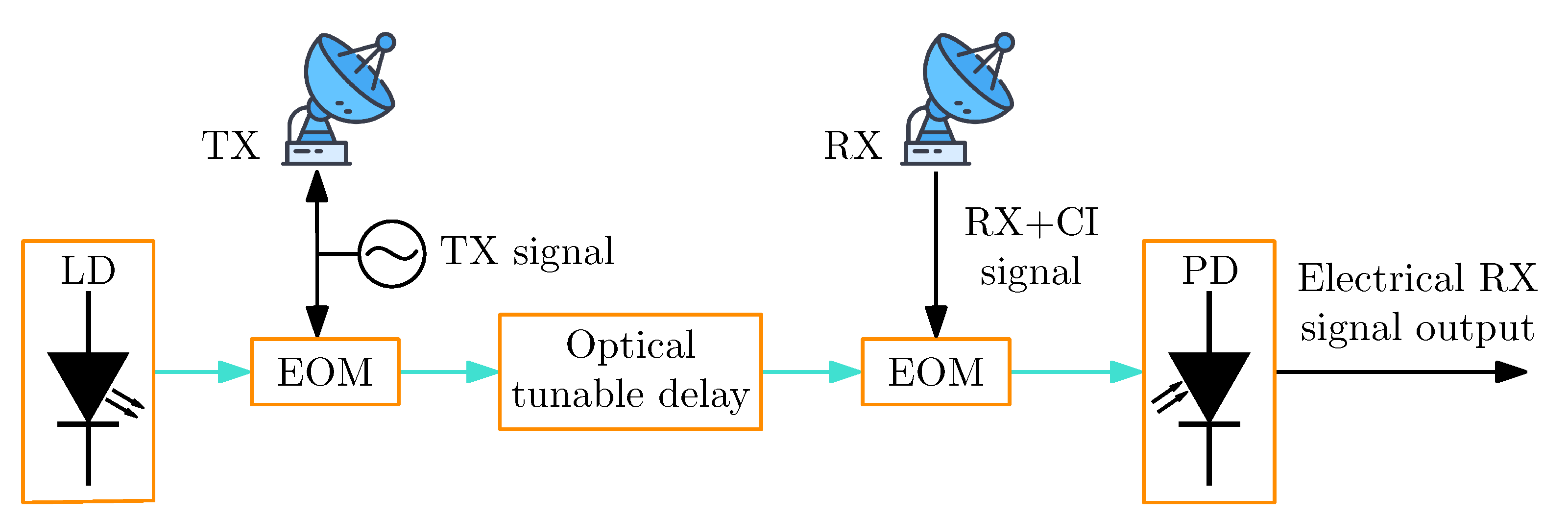
2.6. Co-Site Interference Suppression

During a radar system operation, part of the signal emitted by the transmitter may be received as cross-talk at the receiver. This is undesirable because it can saturate the receiver and prevent the detection of weak signals reflected from the target. One straightforward solution is to use pulse radar, which alternates the operation of the transmitter and receiver. In this method, the transmitter emits a signal for a short period while the receiver is disabled. The duration of the pulse must be much shorter than the time it takes for the signal to travel to the target and back, ensuring that the transmitter is off when the receiver collects the reflected signal. However, this approach introduces “dead zones”, which are periods when the radar system is unable to detect any targets.
Another common approach is to use advanced radar waveforms, such as FMCWs, where the radar transmits continuously but at varying frequencies. Since reflection from the target is delayed, the instantaneous frequency of the transmitted signal differs from that of the received signal. This difference allows the receiver to distinguish between co-site interference and the reflected signal. In conventional systems, co-site-interference cancellation is typically performed in the electrical domain, but this approach faces limitations at high frequencies and large bandwidths. To overcome these constraints, various optical solutions have been proposed to cancel the co-site interference at higher frequencies and over large bandwidths [91,92,96,97,98]. Figure 9 shows a classical method for suppressing the co-site interference, i.e., coherent cancellation in the optical domain, where a mitigation signal with the same amplitude but opposite phase to the interference is generated and then combined coherently with the received signal [91,92,97,98].

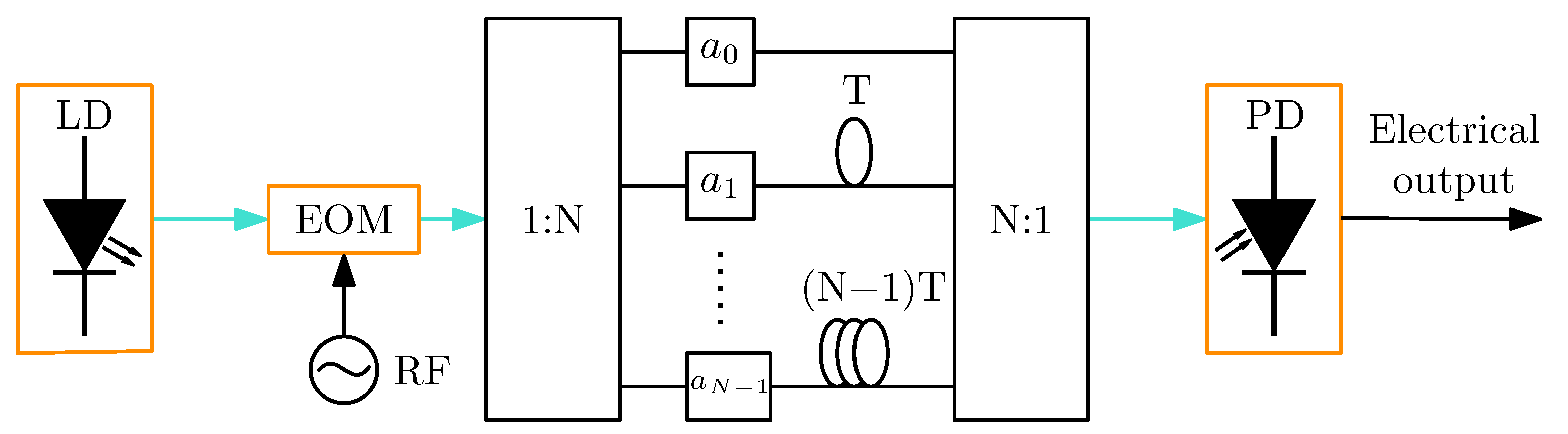
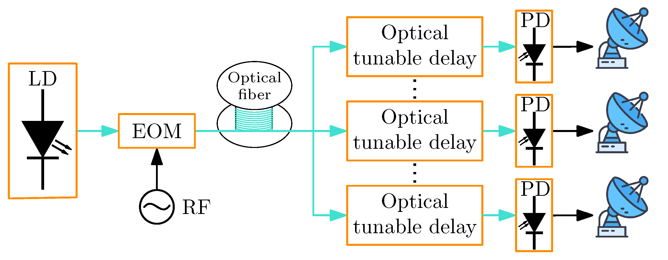
2.7. Optical Beamforming Networks

Radar-phased array networks are commonly used in various remote sensing applications. Traditionally, these networks were implemented using phase shifters, but their bandwidth is very limited due to beam squint [99,100]. Beam squint is an effect where the beam angle changes depending on the frequency and is closely related to the signal’s bandwidth. The greater the signal bandwidth is, the more pronounced the beam squint becomes. By employing optical beamforming networks, the benefits of microwave photonic links can be integrated into phased-array radar systems [101,102,103]. This can also solve the problem of beam squint.
The scheme of a typical optical beamforming network is shown in Figure 10. It consists of a laser source modulated by an RF signal, which is then transmitted through a delay element and detected by a photodiode. To achieve an RF frequency response with a controllable linear phase, the phase delay introduced by the delay element must have a linear phase response over the operational optical band [8]. Solutions are based on the adjustment of the length or the dispersive properties of the transmission fiber [103,104,105,106,107,108], Fourier-domain optical processors [109] and thermally tuned integrated ring resonators [110] have been proposed to introduce tunable delays in fiber links.
While fiber-based delay lines provide high delay-bandwidth products and flexibility, their reliance on long fiber spools introduces practical challenges, such as increased system size, added weight, and mechanical stability issues, especially in airborne and mobile radar applications. To address these challenges, recent research has explored integrated photonic beamforming approaches using compact tunable delay elements and photonic integrated circuits [111,112], which offer a smaller footprint, improved mechanical stability, and lower power consumption.

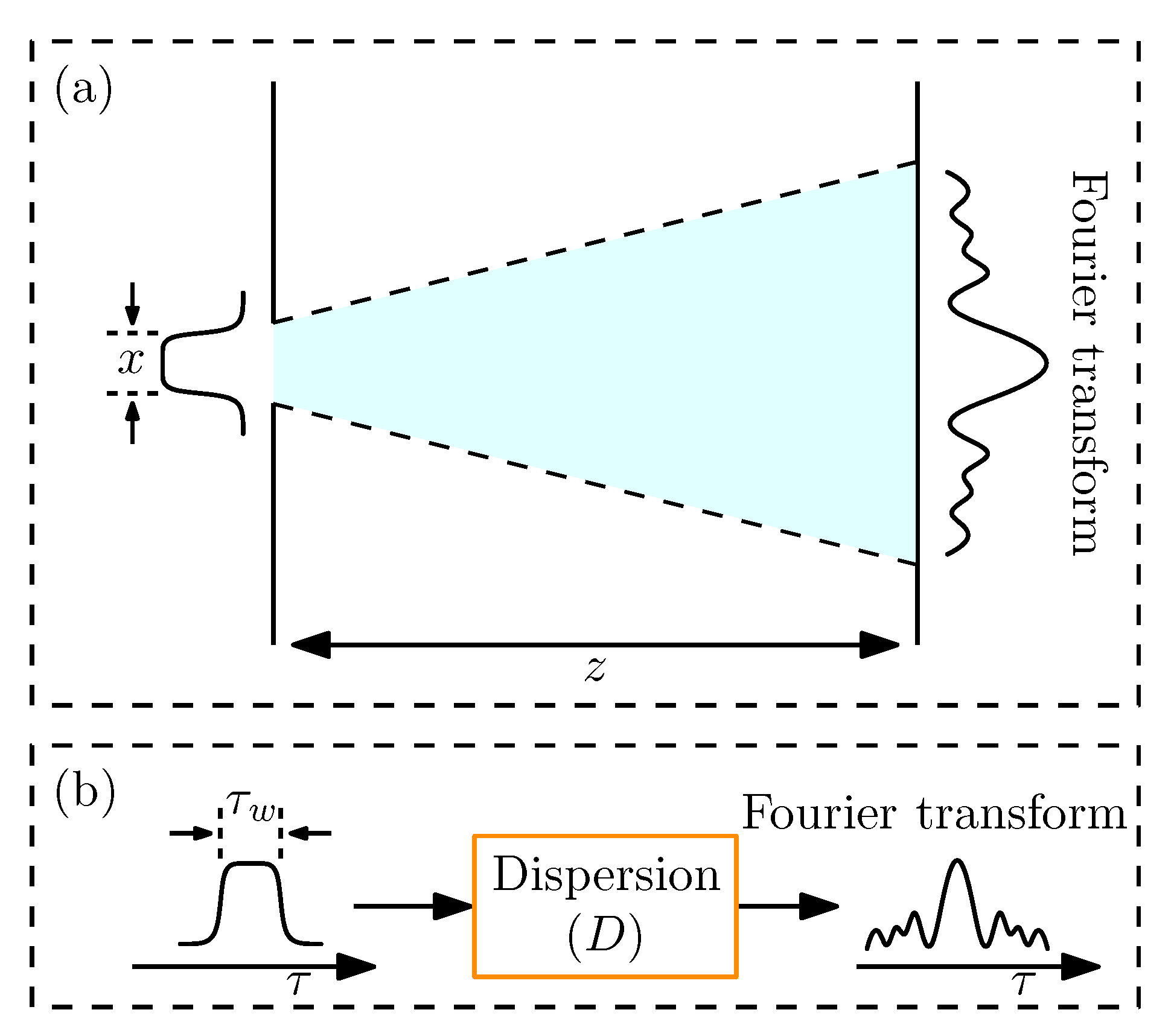
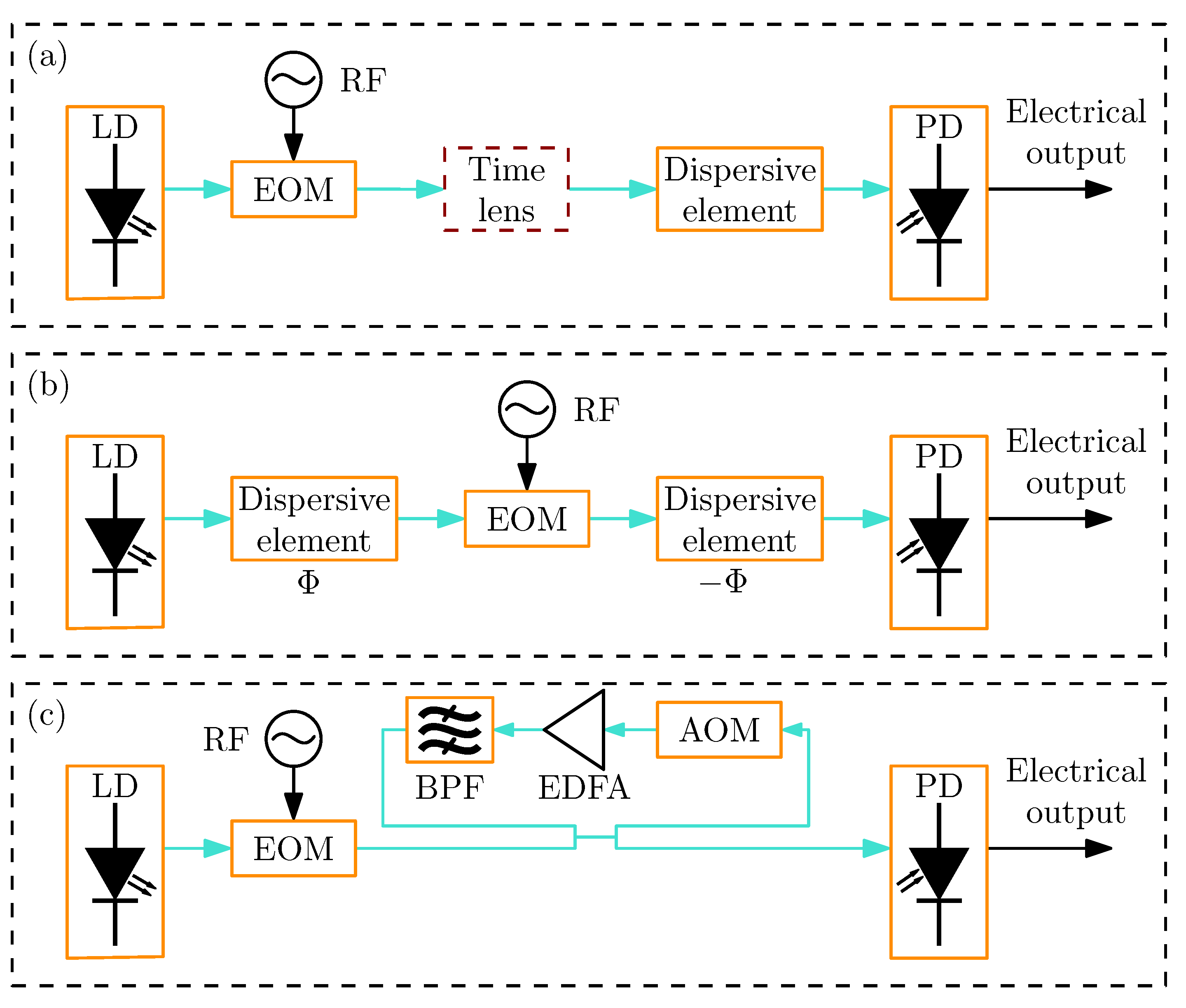
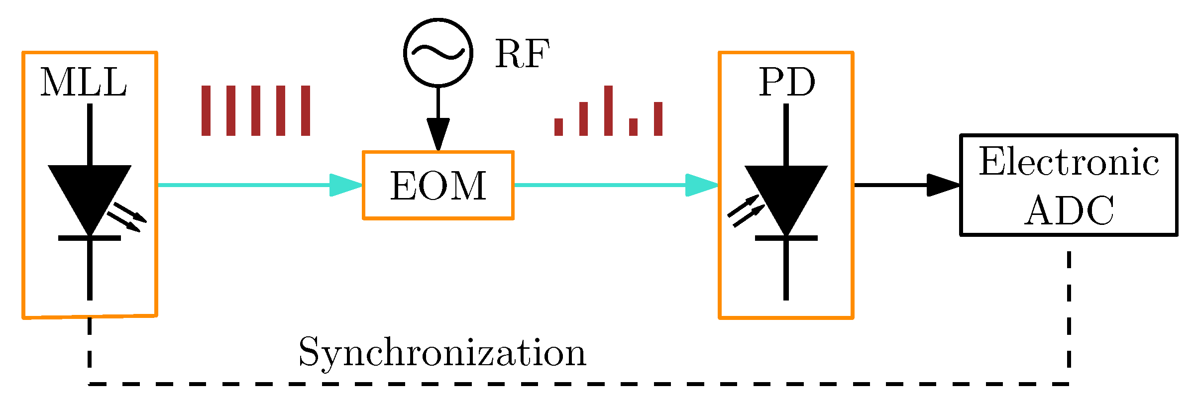
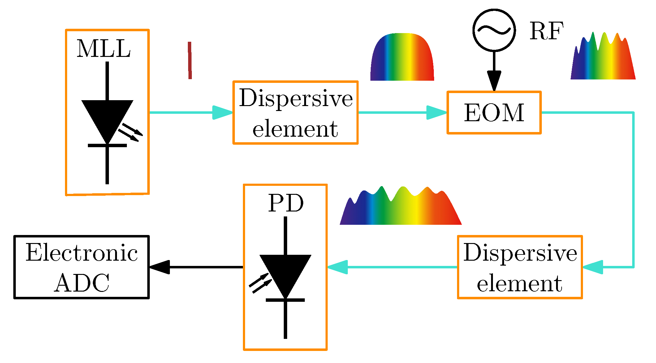
2.8. Optical Real-Time Fourier Transformation

Conventional radar uses digital processing to implement spectral analysis via the Fourier transformation, which is crucial for radar signal processing. However, this method is constrained by the quality, speed, and bandwidth of the ADC in the system. To overcome the limitations of digital spectral analysis, the use of photonic elements for optical RTFT has been proposed [113,114,115,116,117,118,119,120,121].
RTFT is based on the concept of space–time duality. This refers to a parallel between the paraxial diffraction of beams through space and the dispersion of narrow-band pulses through dielectric media in time [114]. The far-field or Fraunhofer diffraction regime represents the simplest spatial propagation geometry that exemplifies this duality. As illustrated in Figure 11a, when light diffracts through a slit, it generates a spatial pattern at a distant point in the far field that resembles the Fourier transformation of the incident beam. For this phenomenon to occur, the distance from the screen has to be
z k x 2 ,
where k is a propagation constant and x is the size of the input aperture. A similar phenomenon occurs when a signal propagates through a highly dispersive medium, as shown in Figure 11b. There, the dispersive medium’s group delay dispersion D has to be
D τ w 2 ,
where τ w 2 is the temporal width of the input waveform [122]. By modulating the optical source, the RTFT of a wanted signal can be realized. The frequency resolution of the dispersion-based RTFT is determined by the dispersion value of the dispersive element; a larger dispersion value results in a higher frequency resolution.
Another method of RTFT involves the use of a time lens, which is a cascade of a dispersive element (such as an optical fiber or fiber grating), a phase modulator, and a dispersive element [123]. Figure 12a illustrates a scheme for time-lens dispersion-based RTFT. A temporal convolution-based RTFT method is shown in Figure 12b. In this method, an ultrashort optical impulse is generated and then stretched by a dispersive element. The pulse is subsequently modulated with an RF signal in MZM and compressed back by another dispersive element. The spectrum of the RF signal can then be measured using a high-sample-rate oscilloscope connected to a photodiode [117,124]. Figure 12c demonstrates the realization of RTFT using a frequency-shifted loop, which has the advantage of not having a limitation on the time window and can therefore be applied to the measurement of infinitely long signals. However, its bandwidth is limited to only tens of MHz, constrained by the frequency shift of the acousto-optic modulator [125].
In recent years, another promising technique for RTFT has emerged using integrated silicon photonics [119,120,121]. This approach enables the miniaturization of optical spectrometers but introduces performance trade-offs compared to traditional implementations. These include limitations in operating bandwidth, measurement speed, spectral resolution, and dynamic range. The compact size and low power consumption of integrated photonic chips make them a viable solution for RTFT in applications where size, weight, and power are constrained, such as in drones. However, this technology has yet to be tested in radar systems.

2.9. Analog-to-Digital Converters

With the increasing demand for multifunctionality and software-defined operation in modern radar systems, it is widely accepted that as much signal processing as possible should be performed in the digital domain. As a result, high-performance ADCs are essential for integrating radar systems with DSP systems. However, as radar systems migrate to higher frequencies, ADCs require higher sampling rates, wider analog bandwidths, and a higher effective number of bits, which are challenging to achieve with traditional ADCs [8].
Using photonic components with wide bandwidth and high stability, we can significantly enhance the performance of ADCs [126,127]. Two main types of photonic ADCs have been demonstrated in radar systems: photonic sampling ADCs and photonic preprocessing ADCs. Using an MLL, optical pulses in the femtosecond range can be generated [128], functioning similarly to Dirac pulses, which are ideal for sampling analog signals. A schematic of a photonic sampling ADC is shown in Figure 13. In this setup, the MLL generates short pulses that are intensity modulated by an EOM. The modulated optical pulses are then converted to the electrical domain via a photodiode and subsequently sampled by an ADC synchronized with the MLL. This approach enhances the analog bandwidth of the ADC, although it does not directly increase the sampling frequency. However, with minor modifications, it allows for parallelization or the use of multiple ADCs, thereby summing the sample rates of all ADCs. The concept of photonic sampling ADCs can be traced back to [129,130].
Photonic preprocessing enables the simpler conversion of signals to the digital domain. A schematic of a photonic preprocessing ADC is shown in Figure 14. In this method, signal preprocessing involves the expansion of the time domain [131]. The short pulse from the MLL is modulated by the analog signal, broadened spectrally, and then converted to the electrical domain via a photodiode. The time-expanded signal is fed into the ADC, which simplifies conversion to the digital domain. However, a drawback of this approach is the slower conversion speed, which limits its application in systems that require rapid processing.
Recently, integrated photonic ADCs have been gaining a lot of attention [132]. Various approaches have been proposed, including schemes based on spectral slicing [133,134], time and wavelength interleaving [80,135], and combinations of wavelength-division multiplexing (WDM) and mode-division multiplexing (MDM) [136]. While some of these techniques show promising results, most have yet to achieve performance levels that are satisfactory for practical radar applications.

3. In-Field Demonstrations of Microwave Photonic Radar

As highlighted in this review paper, many applications of MWP in radar systems have been demonstrated in the literature. However, relatively few have been validated in real-world scenarios, where factors such as atmospheric attenuation, temperature variations, vibrations, and other environmental effects can affect system performance. Some notable field demonstrations of MWP-based radar systems are summarized below.
In [137], an in-field demonstration of a photonic coherent MIMO distributed radar network was presented. The experiment verified the system’s capability for long-range coherent signal distribution and demonstrated successful target detection in an outdoor environment. A fully photonics-based digital coherent radar system was demonstrated and tested in a real-world scenario in [138], confirming its ability to maintain high-resolution performance outside laboratory conditions. Additionally, a photonics-assisted radar system for target cluster detection was reported in [139]. This demonstration showcased the effectiveness of MWP technology in resolving closely spaced targets and confirmed the robustness of the photonic front-end under real environmental conditions.
These field tests show the practical feasibility of applying MWP technologies to radar systems, confirming key advantages such as wide-bandwidth operation, low phase noise, and high spatial resolution in non-ideal, real-world environments. Nevertheless, further field tests are needed to fully assess long-term reliability and performance under varying environmental and operational conditions.

4. Conclusions

MWP offers a promising solution to the limitations of traditional radar systems. Using the unique properties of light and optical components, MWP enables advances in radar performance, including increased bandwidth, reduced phase noise, improved EMI resilience, and enhanced spatial resolution.
This paper has explored key MWP techniques applicable to various radar functionalities. We have discussed how MWP can be used for signal transmission, LO signal generation, radar waveforming, optical beamforming networks, mixing, filtering, co-site interference suppression, RTFT, and ADC. These advances have the potential to revolutionize radar systems, enabling lower power consumption, operation in higher frequency bands, and greater precision.
While MWP presents exciting opportunities, challenges such as phase noise mitigation and system complexity remain. Ongoing research is focused on addressing these issues and further refining MWP technologies for radar applications. The potential for increased energy efficiency and enhanced resolution positions MWP as a key enabler for next-generation radar systems, promising to shape the future of radar technology.

Author Contributions

Conceptualization, L.P. and B.B.; Investigation, L.P.; Writing—original draft preparation, L.P.; Writing—review and editing, B.B., A.B. and A.L.; Visualization, L.P.; Supervision, B.B. All authors have read and agreed to the published version of the manuscript.

Funding

This work was supported by the Slovenian Research and Innovation Agency (ARIS) under grants J2-3048 and J2-50072 and research core funding No. P2-0246.

Conflicts of Interest

The authors declare no conflicts of interest.

References

  1. Seeds, A.J.; Williams, K.J. Microwave Photonics. J. Light. Technol. 2006, 24, 4628–4641. [Google Scholar] [CrossRef]
  2. Zhang, F.; Sun, G.; Zhou, Y.; Gao, B.; Pan, S. Towards High-Resolution Imaging With Photonics-Based Time Division Multiplexing MIMO Radar. IEEE J. Sel. Top. Quantum Electron. 2022, 28, 6000310. [Google Scholar] [CrossRef]
  3. De, S.; Raj, A.A.B. A survey on photonics technologies for radar applications. J. Opt. 2023, 52, 90–119. [Google Scholar] [CrossRef]
  4. Blatnik, A.; Zmrzlak, L.; Batagelj, B. Radio Front-End for Frequency Agile Microwave Photonic Radars. Electronics 2024, 13. [Google Scholar] [CrossRef]
  5. Nagatsuma, T.; Horiguchi, S.; Minamikata, Y.; Yoshimizu, Y.; Hisatake, S.; Kuwano, S.; Yoshimoto, N.; Terada, J.; Takahashi, H. Terahertz wireless communications based on photonics technologies. Opt. Express 2013, 21, 23736–23747. [Google Scholar] [CrossRef]
  6. Pinna, S.; Melo, S.; Laghezza, F.; Scotti, F.; Lazzeri, E.; Scaffardi, M.; Ghelfi, P.; Bogoni, A. Photonics-Based Radar for Sub-mm Displacement Sensing. IEEE J. Sel. Top. Quantum Electron. 2017, 23, 168–175. [Google Scholar] [CrossRef]
  7. Serafino, G.; Scotti, F.; Lembo, L.; Hussain, B.; Porzi, C.; Malacarne, A.; Maresca, S.; Onori, D.; Ghelfi, P.; Bogoni, A. Toward a New Generation of Radar Systems Based on Microwave Photonic Technologies. J. Light. Technol. 2019, 37, 643–650. [Google Scholar] [CrossRef]
  8. Pan, S.; Zhang, Y. Microwave Photonic Radars. J. Light. Technol. 2020, 38, 5450–5484. [Google Scholar] [CrossRef]
  9. Zhang, F.; Guo, Q.; Pan, S. Photonics-based real-time ultra-high-range-resolution radar with broadband signal generation and processing. Sci. Rep. 2017, 7, 13848. [Google Scholar] [CrossRef]
  10. Harmuth, H.F. Frequency-Sharing and Spread-Spectrum Transmission with Large Relative Bandwidth. IEEE Trans. Electromagn. Compat. 1978, EMC-20, 232–239. [Google Scholar] [CrossRef]
  11. Waldschmidt, C.; Hasch, J.; Menzel, W. Automotive Radar — From First Efforts to Future Systems. IEEE J. Microwaves 2021, 1, 135–148. [Google Scholar] [CrossRef]
  12. Yi, L.; Li, Y.; Nagatsuma, T. Photonic Radar for 3D Imaging: From Millimeter to Terahertz Waves. IEEE J. Sel. Top. Quantum Electron. 2023, 29, 8500714. [Google Scholar] [CrossRef]
  13. Batra, A.; Barowski, J.; Damyanov, D.; Wiemeler, M.; Rolfes, I.; Schultze, T.; Balzer, J.C.; Göhringer, D.; Kaiser, T. Short-Range SAR Imaging From GHz to THz Waves. IEEE J. Microwaves 2021, 1, 574–585. [Google Scholar] [CrossRef]
  14. Yi, L.; Nishida, Y.; Sagisaka, T.; Kaname, R.; Mizuno, R.; Fujita, M.; Nagatsuma, T. Towards Practical Terahertz Imaging System With Compact Continuous Wave Transceiver. J. Light. Technol. 2021, 39, 7850–7861. [Google Scholar] [CrossRef]
  15. Tratnik, J.; Lemut, P.; Vidmar, M. Time-transfer and synchronization equipment for high-performance particle accelerators. J. Microelectron. Electron. Components Mater. 2012, 42, 115–122. [Google Scholar]
  16. Koala, R.A.S.D.; Fujita, M.; Nagatsuma, T. Nanophotonics-inspired all-silicon waveguide platforms for terahertz integrated systems. Nanophotonics 2022, 11, 1741–1759. [Google Scholar] [CrossRef]
  17. Strömbeck, F.; Yan, Y.; Zirath, H. A Beyond 100-Gbps Polymer Microwave Fiber Communication Link at D-Band. IEEE Trans. Circuits Syst. I Regul. Pap. 2023, 70, 3017–3028. [Google Scholar] [CrossRef]
  18. Samarasekera, A.C.J.; Fernández, S.L.; Feger, R.; Hüttner, R.; Gruson, F.; Krainer, S.; Stelzer, A. Distributed Radar Network with Polymer Microwave Fiber (PMF) Based Synchronization. In Proceedings of the 2024 IEEE Topical Conference on Wireless Sensors and Sensor Networks (WiSNeT), San Antonio, TX, USA, 21–24 January 2024; pp. 1–4. [Google Scholar] [CrossRef]
  19. Reynaert, P.; Dens, K.; D’heer, C.; Simic, D.; Vaes, J.; Philippe, B.; Ooms, S. Polymer Microwave Fiber: A New Communication Concept That Blends Wireless, Wireline and Optical Communication. In Proceedings of the 2019 26th IEEE International Conference on Electronics, Circuits and Systems (ICECS), Genoa, Italy, 27–29 November 2019; pp. 755–758. [Google Scholar] [CrossRef]
  20. Dragonja, U.; Tratnik, J.; Batagelj, B. Use of copper-coated fiber as a tunable optical time-delay line in precise timing systems. Opt. Quantum Electron. 2013, 45, 1229–1235. [Google Scholar] [CrossRef]
  21. Podbregar, L.; Dragonja, U.; Krč, J.; Czermann, M.; Blatnik, A.; Batagelj, B. Sensitivity of radio frequency phase stabilization system to temperature changes in a fiber optic link. In Proceedings of the 2024 7th International Balkan Conference on Communications and Networking (BalkanCom), Ljubljana, Slovenia, 3–6 June 2024; pp. 143–147. [Google Scholar] [CrossRef]
  22. Wang, K.; Wei, W.; Wang, D.; Wang, P.; Xie, W.; Dong, Y. Distributed receiving system with local digitization and combination for SNR enhancement. Opt. Express 2023, 31, 1014–1024. [Google Scholar] [CrossRef]
  23. Hu, C.; Luo, B.; Bai, W.; Pan, W.; Yan, L.; Zou, X. Stable Radio Frequency Transmission of Single Optical Source Over Fiber Based on Passive Phase Compensation. IEEE Photonics J. 2021, 13, 7200607. [Google Scholar] [CrossRef]
  24. Tratnik, J.; Dragonja, U.; Batagelj, B. Multi-purpose constant-delay optical link. In Proceedings of the 2014 European Frequency and Time Forum (EFTF), Neuchatel, Switzerland, 23–26 June 2014; pp. 333–335. [Google Scholar] [CrossRef]
  25. Ben-Amram, A.; Stern, Y.; London, Y.; Antman, Y.; Zadok, A. Stable closed-loop fiber-optic delay of arbitrary radio-frequency waveforms. Opt. Express 2015, 23, 28244–28257. [Google Scholar] [CrossRef]
  26. Sun, S.; Petropulu, A.P.; Poor, H.V. MIMO Radar for Advanced Driver-Assistance Systems and Autonomous Driving: Advantages and Challenges. IEEE Signal Process. Mag. 2020, 37, 98–117. [Google Scholar] [CrossRef]
  27. Kruse, S.; Gudyriev, S.; Schwabe, T.; Kneuper, P.; Kurz, H.G.; Scheytt, J.C. Silicon Photonic Radar Transmitter IC for mm-Wave Large Aperture MIMO Radar Using Optical Clock Distribution. IEEE Microw. Wirel. Components Lett. 2021, 31, 783–786. [Google Scholar] [CrossRef]
  28. Kruse, S.; Gudyriev, S.; Kneuper, P.; Schwabe, T.; Meinecke, M.M.; Kurz, H.G.; Scheytt, J.C. Silicon Photonic Radar Receiver IC for mm-Wave Large Aperture MIMO Radar Using Optical Clock Distribution. IEEE Microw. Wirel. Components Lett. 2022, 32, 1447–1450. [Google Scholar] [CrossRef]
  29. Ishio, H.; Minowa, J.; Nosu, K. Review and status of wavelength-division-multiplexing technology and its application. J. Light. Technol. 1984, 2, 448–463. [Google Scholar] [CrossRef]
  30. Cvijetic, N.; Qian, D.; Yu, J.; Huang, Y.K.; Wang, T. Polarization-Multiplexed Optical Wireless Transmission With Coherent Detection. J. Light. Technol. 2010, 28, 1218–1227. [Google Scholar] [CrossRef]
  31. Kikuchi, K. Performance analyses of polarization demultiplexing based on constant-modulus algorithm in digital coherent optical receivers. Opt. Express 2011, 19, 9868–9880. [Google Scholar] [CrossRef]
  32. Chen, Z.Y.; Yan, L.S.; Pan, Y.; Jiang, L.; Yi, A.L.; Pan, W.; Luo, B. Use of polarization freedom beyond polarization-division multiplexing to support high-speed and spectral-efficient data transmission. Light. Sci. Appl. 2017, 6, e16207. [Google Scholar] [CrossRef]
  33. Badraoui, N.; Berceli, T. Enhancing capacity of optical links using polarization multiplexing. Opt. Quantum Electron. 2019, 51, 310. [Google Scholar] [CrossRef]
  34. Puttnam, B.J.; Rademacher, G.; Luís, R.S. Space-division multiplexing for optical fiber communications. Optica 2021, 8, 1186–1203. [Google Scholar] [CrossRef]
  35. Majumder, S.P.; Hossain, A. Performance analysis of an SDM-WDM multicore optical fiber link. Opt. Contin. 2023, 2, 600–615. [Google Scholar] [CrossRef]
  36. Berdagué, S.; Facq, P. Mode division multiplexing in optical fibers. Appl. Opt. 1982, 21, 1950–1955. [Google Scholar] [CrossRef] [PubMed]
  37. Hanzawa, N.; Saitoh, K.; Sakamoto, T.; Matsui, T.; Tomita, S.; Koshiba, M. Demonstration of mode-division multiplexing transmission over 10 km two-mode fiber with mode coupler. In Proceedings of the 2011 Optical Fiber Communication Conference and Exposition and the National Fiber Optic Engineers Conference, Los Angeles, CA, USA, 6–10 March 2011; pp. 1–3. [Google Scholar]
  38. Ryf, R.; Randel, S.; Gnauck, A.H.; Bolle, C.; Sierra, A.; Mumtaz, S.; Esmaeelpour, M.; Burrows, E.C.; Essiambre, R.J.; Winzer, P.J.; et al. Mode-Division Multiplexing Over 96 km of Few-Mode Fiber Using Coherent 6 ×6 MIMO Processing. J. Light. Technol. 2012, 30, 521–531. [Google Scholar] [CrossRef]
  39. Sillard, P.; Bigot-Astruc, M.; Molin, D. Few-Mode Fibers for Mode-Division-Multiplexed Systems. J. Light. Technol. 2014, 32, 2824–2829. [Google Scholar] [CrossRef]
  40. Rademacher, G.; Puttnam, B.J.; Luís, R.S.; Sakaguchi, J.; Klaus, W.; Eriksson, T.A.; Awaji, Y.; Hayashi, T.; Nagashima, T.; Nakanishi, T.; et al. 10.66 Peta-Bit/s Transmission over a 38-Core-Three-Mode Fiber. In Proceedings of the 2020 Optical Fiber Communications Conference and Exhibition (OFC), San Diego, CA, USA, 8–12 March 2020; pp. 1–3. [Google Scholar]
  41. Maher, R.; Xu, T.; Galdino, L.; Sato, M.; Alvarado, A.; Shi, K.; Savory, S.J.; Thomsen, B.C.; Killey, R.I.; Bayvel, P. Spectrally Shaped DP-16QAM Super-Channel Transmission with Multi-Channel Digital Back-Propagation. Sci. Rep. 2015, 5, 8214. [Google Scholar] [CrossRef]
  42. Luo, L.W.; Ophir, N.; Chen, C.P.; Gabrielli, L.H.; Poitras, C.B.; Bergmen, K.; Lipson, M. WDM-compatible mode-division multiplexing on a silicon chip. Nat. Commun. 2014, 5, 3069. [Google Scholar] [CrossRef]
  43. Yao, J. Microwave Photonics: Photonic Generation of Microwave and Millimeter-wave Signals. Int. J. Microw. Opt. Technol. 2010, 5. [Google Scholar]
  44. Wei, J.; Zhang, S.; Kim, J.; Pan, S. Compact Phase Detector for Optical-Microwave Synchronization Using Polarization Modulation. J. Light. Technol. 2018, 36, 4267–4272. [Google Scholar] [CrossRef]
  45. Ponnampalam, L.; Fice, M.J.; Pozzi, F.; Renaud, C.C.; Rogers, D.C.; Lealman, I.F.; Moodie, D.G.; Cannard, P.J.; Lynch, C.; Johnston, L.; et al. Monolithically Integrated Photonic Heterodyne System. J. Light. Technol. 2011, 29, 2229–2234. [Google Scholar] [CrossRef]
  46. Steed, R.J.; Ponnampalam, L.; Fice, M.J.; Renaud, C.C.; Rogers, D.C.; Moodie, D.G.; Maxwell, G.D.; Lealman, I.F.; Robertson, M.J.; Pavlovic, L.; et al. Hybrid Integrated Optical Phase-Lock Loops for Photonic Terahertz Sources. IEEE J. Sel. Top. Quantum Electron. 2011, 17, 210–217. [Google Scholar] [CrossRef]
  47. Zhang, F.; Pan, S. Microwave photonic signal generation for radar applications. In Proceedings of the 2016 IEEE International Workshop on Electromagnetics: Applications and Student Innovation Competition (iWEM), Nanjing, China, 16–18 May 2016; pp. 1–3. [Google Scholar] [CrossRef]
  48. Zhou, W.; Blasche, G. Injection-locked dual opto-electronic oscillator with ultra-low phase noise and ultra-low spurious level. IEEE Trans. Microw. Theory Tech. 2005, 53, 929–933. [Google Scholar] [CrossRef]
  49. Hao, T.; Liu, Y.; Tang, J.; Cen, Q.; Li, W.; Zhu, N.; Dai, Y.; Capmany, J.; Yao, J.; Li, M. Recent advances in optoelectronic oscillators. Adv. Photonics 2020, 2, 044001. [Google Scholar] [CrossRef]
  50. Bogataj, L.; Vidmar, M.; Batagelj, B. A Feedback Control Loop for Frequency Stabilization in an Opto-Electronic Oscillator. J. Light. Technol. 2014, 32, 3690–3694. [Google Scholar] [CrossRef]
  51. Batagelj, B.; Bogataj, L.; Vidmar, M. Key properties and design issues for an opto-electronic oscillator. In Proceedings of the 2015 17th International Conference on Transparent Optical Networks (ICTON), Budapest, Hungary, 5–9 July 2015; pp. 1–4. [Google Scholar] [CrossRef]
  52. Bogataj, L.; Vidmar, M.; Batagelj, B. Improving the Side-mode Suppression Ratio and Reducing the Frequency Drift in an Opto-Electronic Oscillator With a Feedback Control Loop and Additional Phase Modulation. J. Light. Technol. 2016, 34, 885–890. [Google Scholar] [CrossRef]
  53. Bogataj, L.; Vidmar, M.; Batagelj, B. Opto-Electronic Oscillator With Quality Multiplier. IEEE Trans. Microw. Theory Tech. 2016, 64, 663–668. [Google Scholar] [CrossRef]
  54. Li, M.; Hao, T.; Yang, Y.; Shi, N.; Li, W. Recent advances in optoelectronic oscillators and quantum microwave photonics. In Proceedings of the 2021 International Topical Meeting on Microwave Photonics (MWP), Pisa, Italy, 15–17 November 2021; pp. 1–3. [Google Scholar] [CrossRef]
  55. Ilgaz, M.A.; Batagelj, B. Opto-Electronic Oscillators for Micro- and Millimeter Wave Signal Generation. Electronics 2021, 10, 857. [Google Scholar] [CrossRef]
  56. Fu, Z.; Ma, Y.; Zeng, Z.; Zhang, L.; Tian, H.; Lyu, W.; Zhang, Y.; Zhang, Z.; Zhang, S.; Li, H.; et al. Microwave local oscillator signal generation with low near-carrier phase noise based on cascaded optoelectronic oscillators. Opt. Laser Technol. 2025, 181, 111628. [Google Scholar] [CrossRef]
  57. Liu, Q.; Peng, J.; Yan, J. Optoelectronic Oscillators: Progress from Classical Designs to Integrated Systems. Photonics 2025, 12, 120. [Google Scholar] [CrossRef]
  58. Qi, G.; Yao, J.; Seregelyi, J.; Paquet, S.; Belisle, C. Generation and distribution of a wide-band continuously tunable millimeter-wave signal with an optical external modulation technique. IEEE Trans. Microw. Theory Tech. 2005, 53, 3090–3097. [Google Scholar] [CrossRef]
  59. Lavrič, A.; Batagelj, B. Phase Noise Measurement for Improving the Performance of High-Order Modulation Scheme Wireless Links. In Proceedings of the 2024 7th International Balkan Conference on Communications and Networking (BalkanCom), Ljubljana, Slovenia, 3–6 June 2024; pp. 148–152. [Google Scholar] [CrossRef]
  60. Stöhr, A.; Babiel, S.; Cannard, P.J.; Charbonnier, B.; van Dijk, F.; Fedderwitz, S.; Moodie, D.; Pavlovic, L.; Ponnampalam, L.; Renaud, C.C.; et al. Millimeter-Wave Photonic Components for Broadband Wireless Systems. IEEE Trans. Microw. Theory Tech. 2010, 58, 3071–3082. [Google Scholar] [CrossRef]
  61. Luo, H.; Yu, J.; Wang, J.; Ma, C.; Han, X.; Su, X.; Gao, Y.; Jia, S. Microwave Photonic Frequency Multiplier with Low Phase Noise Based on an Optoelectronic Oscillator. Photonics 2024, 11, 588. [Google Scholar] [CrossRef]
  62. Peng, M.Y.; Kalaydzhyan, A.; Kärtner, F.X. Balanced optical-microwave phase detector for sub-femtosecond optical-RF synchronization. Opt. Express 2014, 22, 27102–27111. [Google Scholar] [CrossRef] [PubMed]
  63. Hasanuzzaman, G.K.M.; Iezekiel, S.; Kanno, A. W-Band Optoelectronic Oscillator. IEEE Photonics Technol. Lett. 2020, 32, 771–774. [Google Scholar] [CrossRef]
  64. Luchinin, A.; Malygin, I. Optoelectronic Microwave Oscillator. Advantages and Disadvantages. Noise Sources in an OEO. In Proceedings of the 2024 IEEE Ural-Siberian Conference on Biomedical Engineering, Radioelectronics and Information Technology (USBEREIT), Yekaterinburg, Russia, 13–15 May 2024; pp. 333–337. [Google Scholar] [CrossRef]
  65. Kaba, M.; Li, H.W.; Daryoush, A.; Vilcot, J.P.; Decoster, D.; Chazelas, J.; Bouwmans, G.; Quiquempois, Y.; Deborgies, F. Improving thermal stability of opto-electronic oscillators. IEEE Microw. Mag. 2006, 7, 38–47. [Google Scholar] [CrossRef]
  66. Zhu, X.; Wei, W.; Xie, W.; Dong, Y. Long-Term Stable Optoelectronic Oscillator Based on Phase-Locked Loop. In Proceedings of the 2023 IEEE 7th International Symposium on Electromagnetic Compatibility (ISEMC), Hangzhou, China, 20–23 October 2023; pp. 1–3. [Google Scholar] [CrossRef]
  67. Eliyahu, D.; Sariri, K.; Kamran, A.; Tokhmakhian, M. Improving short and long term frequency stability of the opto-electronic oscillator. In Proceedings of the 2002 IEEE International Frequency Control Symposium and PDA Exhibition (Cat. No.02CH37234), New Orleans, LA, USA, 31 May 2002; pp. 580–583. [Google Scholar] [CrossRef]
  68. Wang, C.; Yao, J. Photonic Generation of Chirped Microwave Pulses Using Superimposed Chirped Fiber Bragg Gratings. IEEE Photonics Technol. Lett. 2008, 20, 882–884. [Google Scholar] [CrossRef]
  69. Li, M.; Shao, L.Y.; Albert, J.; Yao, J. Tilted Fiber Bragg Grating for Chirped Microwave Waveform Generation. IEEE Photonics Technol. Lett. 2011, 23, 314–316. [Google Scholar] [CrossRef]
  70. Rashidinejad, A.; Weiner, A.M. Photonic Radio-Frequency Arbitrary Waveform Generation With Maximal Time-Bandwidth Product Capability. J. Light. Technol. 2014, 32, 3383–3393. [Google Scholar] [CrossRef]
  71. Zhou, P.; Zhang, F.; Guo, Q.; Pan, S. Linearly chirped microwave waveform generation with large time-bandwidth product by optically injected semiconductor laser. Opt. Express 2016, 24, 18460–18467. [Google Scholar] [CrossRef]
  72. Zhou, P.; Zhang, F.; Guo, Q.; Li, S.; Pan, S. Reconfigurable Radar Waveform Generation Based on an Optically Injected Semiconductor Laser. IEEE J. Sel. Top. Quantum Electron. 2017, 23, 1801109. [Google Scholar] [CrossRef]
  73. Nakarmi, B.; Chen, H.; Ukaegbu, I.A.; Gaudel, B.; Nakarmi, U.; Muthaiyah, S.; Ng, A.; Wang, X.; Pan, S. Linear Frequency Modulated Photonics RADAR using Injection Locking in Semiconductor Laser. In Proceedings of the 2021 International Conference on Electronics, Communications and Information Technology (ICECIT), Khulna, Bangladesh, 14–16 September 2021; pp. 1–4. [Google Scholar] [CrossRef]
  74. Kumar, C.; Raghuwanshi, S.K.; Yadav, R.K. A review on photonic-assisted dual-chirp microwave waveform generation methods. Microw. Opt. Technol. Lett. 2024, 66, e34266. [Google Scholar] [CrossRef]
  75. Yao, Y.; Zhang, F.; Zhang, Y.; Ye, X.; Zhu, D.; Pan, S. Demonstration of Ultra-high-resolution Photonics-based Kaband Inverse Synthetic Aperture Radar Imaging. In Proceedings of the 2018 Optical Fiber Communications Conference and Exposition (OFC), San Diego, CA, USA, 11–15 March 2018; pp. 1–3. [Google Scholar]
  76. Guo, Q.; Zhang, F.; Zhou, P.; Pan, S. Dual-Band LFM Signal Generation by Optical Frequency Quadrupling and Polarization Multiplexing. IEEE Photonics Technol. Lett. 2017, 29, 1320–1323. [Google Scholar] [CrossRef]
  77. Zhang, F.; Gao, B.; Pan, S. Arbitrary waveform generation by a 4-bit photonic digital-to-analog converter with 3.49 effective number of bits. In Proceedings of the 2016 IEEE International Topical Meeting on Microwave Photonics (MWP), Long Beach, CA, USA, 31 October–3 November 2016; pp. 137–140. [Google Scholar] [CrossRef]
  78. Peng, S.; Li, S.; Xue, X.; Xiao, X.; Wu, D.; Zheng, X.; Zhou, B. High-resolution W-band ISAR imaging system utilizing a logic-operation-based photonic digital-to-analog converter. Opt. Express 2018, 26, 1978–1987. [Google Scholar] [CrossRef]
  79. Li, J.; Xue, X.; Zha, Y.; Wu, D.; Li, S.; Zheng, X. A Segmented Photonic Digital-to-analog Converter with a High Effective Number of Bits. In Proceedings of the 2019 International Topical Meeting on Microwave Photonics (MWP), Ottawa, ON, Canada, 7–10 October 2019; pp. 1–3. [Google Scholar] [CrossRef]
  80. García, S.; Ureña, M.; Gasulla, I. Photonic-Assisted Analog-to-Digital Conversion Based on a Dispersion-Diversity Multicore Fiber. IEEE J. Sel. Top. Quantum Electron. 2023, 29, 4300108. [Google Scholar] [CrossRef]
  81. Liu, Z.; Slavík, R. Optical Injection Locking: From Principle to Applications. J. Light. Technol. 2020, 38, 43–59. [Google Scholar] [CrossRef]
  82. Won, Y.S.; Kim, C.H.; Lee, S.G. Range Resolution Improvement of a 24 GHz ISM Band Pulse Radar—A Feasibility Study. IEEE Sens. J. 2015, 15, 7142–7149. [Google Scholar] [CrossRef]
  83. Vokić, N.; Milovančev, D. Photomixing Techniques for mm-Wave Carrier Generation. In Proceedings of the 2024 47th MIPRO ICT and Electronics Convention (MIPRO), Opatija, Croatia, 20–24 May 2024; pp. 1671–1676. [Google Scholar] [CrossRef]
  84. Minasian, R.A.; Chan, E.H.W.; Yi, X. Microwave photonic signal processing. Opt. Express 2013, 21, 22918–22936. [Google Scholar] [CrossRef] [PubMed]
  85. Zhou, Y.; Kong, J.; Zhang, F.; Pan, S. Microwave photonic I/Q mixer for wideband frequency downconversion with serial electro-optical modulations. Opt. Lett. 2024, 49, 65–68. [Google Scholar] [CrossRef]
  86. Tang, Z.; Li, Y.; Yao, J.; Pan, S. Photonics-Based Microwave Frequency Mixing: Methodology and Applications. Laser Photonics Rev. 2020, 14, 1800350. [Google Scholar] [CrossRef]
  87. Kittlaus, E.A.; Eliyahu, D.; Ganji, S.; Williams, S.; Matsko, A.B.; Cooper, K.B.; Forouhar, S. A low-noise photonic heterodyne synthesizer and its application to millimeter-wave radar. Nat. Commun. 2021, 12, 4397. [Google Scholar] [CrossRef]
  88. Yao, J. Microwave Photonics. J. Light. Technol. 2009, 27, 314–335. [Google Scholar] [CrossRef]
  89. Zhu, D.; Pan, S. Photonics-Based Microwave Image-Reject Mixer. Photonics 2018, 5, 6. [Google Scholar] [CrossRef]
  90. Capmany, J.; Mora, J.; Gasulla, I.; Sancho, J.; Lloret, J.; Sales, S. Microwave Photonic Signal Processing. J. Light. Technol. 2013, 31, 571–586. [Google Scholar] [CrossRef]
  91. Han, X.; Huo, B.; Shao, Y.; Wang, C.; Zhao, M. RF Self-Interference Cancellation Using Phase Modulation and Optical Sideband Filtering. IEEE Photonics Technol. Lett. 2017, 29, 917–920. [Google Scholar] [CrossRef]
  92. Chen, Y.; Pan, S. Photonics-Assisted Radio-Frequency Self-Interference Cancellation and Fiber Transmission Using a DP-QPSK modulator. In Proceedings of the 2018 International Topical Meeting on Microwave Photonics (MWP), Toulouse, France, 22–25 October 2018; pp. 1–4. [Google Scholar] [CrossRef]
  93. Zhou, Y.; Wang, L.; Liu, Y.; Yu, Y.; Zhang, X. Microwave Photonic Filters and Applications. Photonics 2023, 10, 1110. [Google Scholar] [CrossRef]
  94. Tao, Z.; Tao, Y.; Jin, M.; Qin, J.; Chen, R.; Shen, B.; Wu, Y.; Shu, H.; Yu, S.; Wang, X. Highly reconfigurable silicon integrated microwave photonic filter towards next-generation wireless communication. Photon. Res. 2023, 11, 682–694. [Google Scholar] [CrossRef]
  95. Porzi, C.; Serafino, G.; Velha, P.; Ghelfi, P.; Bogoni, A. Integrated SOI High-Order Phase-Shifted Bragg Grating for Microwave Photonics Signal Processing. J. Light. Technol. 2017, 35, 4479–4487. [Google Scholar] [CrossRef]
  96. Tu, Z.; Wen, A.; Li, X.; Zhang, H. A Photonic Pre-Distortion Technique for RF Self-Interference Cancellation. IEEE Photonics Technol. Lett. 2018, 30, 1297–1300. [Google Scholar] [CrossRef]
  97. Shi, N.; Song, Q.; Tang, J.; Li, W.; Zhu, N.; Li, M. A switchable self-interference cancellation system for dual-band IBFD system using a monolithic integrated DML array. Opt. Commun. 2019, 447, 55–60. [Google Scholar] [CrossRef]
  98. Wang, H.; Wen, A.; Men, Y.; Wang, Y. Photonics-Based Radar Jamming Signal Generation and Self-Interference Cancellation. J. Light. Technol. 2023, 41, 5922–5929. [Google Scholar] [CrossRef]
  99. Bonjour, R.; Singleton, M.; Leuchtmann, P.; Leuthold, J. Comparison of steering angle and bandwidth for various phased array antenna concepts. Opt. Commun. 2016, 373, 35–43, SI: Microwave photonics. [Google Scholar] [CrossRef]
  100. Abdalrazak, M.Q.; Majeed, A.H.; Abd-Alhameed, R.A. A Critical Examination of the Beam-Squinting Effect in Broadband Mobile Communication: Review Paper. Electronics 2023, 12, 400. [Google Scholar] [CrossRef]
  101. Cheng, Q.; Zheng, S.; Zhang, Q.; Ji, J.; Yu, H.; Zhang, X. An integrated optical beamforming network for two-dimensional phased array radar. Opt. Commun. 2021, 489, 126809. [Google Scholar] [CrossRef]
  102. Duan, F.; Guo, Y.; Gu, Z.; Yin, Y.; Wu, Y.; Chen, T. Optical Beamforming Networks for Millimeter-Wave Wireless Communications. Appl. Sci. 2023, 13, 8346. [Google Scholar] [CrossRef]
  103. Ritoša, P.; Batagelj, B.; Vidmar, M. Optically steerable antenna array for radio over fibre transmission. Electron. Lett. 2005, 41, 917–918. [Google Scholar] [CrossRef]
  104. Ritosa, P.; Vidmar, M. Remote optically controllable antenna array using a single optical fiber for RoF reception. Microw. Opt. Technol. Lett. 2007, 49, 1349–1353. [Google Scholar] [CrossRef]
  105. Shin, J.D.; Lee, B.S.; Kim, B.G. Optical true time-delay feeder for X-band phased array antennas composed of 2/spl times/2 optical MEMS switches and fiber delay lines. IEEE Photonics Technol. Lett. 2004, 16, 1364–1366. [Google Scholar] [CrossRef]
  106. Matthews, P.; Liu, P.L.; Medberry, J.; Franekl, M.; Esman, R. Demonstration of a wide-band fiber-optic nulling system for array antennas. IEEE Trans. Microw. Theory Tech. 1999, 47, 1327–1331. [Google Scholar] [CrossRef]
  107. Ye, X.; Zhang, F.; Pan, S. Compact optical true time delay beamformer for a 2D phased array antenna using tunable dispersive elements. Opt. Lett. 2016, 41, 3956–3959. [Google Scholar] [CrossRef]
  108. Luan, Y.; Yang, T.; Ren, J.; Li, R.; Zhang, Z. Broadband Beam-Scanning Phased Array Based on Microwave Photonics. Electronics 2024, 13, 1278. [Google Scholar] [CrossRef]
  109. Yi, X.; Li, L.; Huang, T.X.H.; Minasian, R.A. Programmable multiple true-time-delay elements based on a Fourier-domain optical processor. Opt. Lett. 2012, 37, 608–610. [Google Scholar] [CrossRef]
  110. Cardenas, J.; Foster, M.A.; Sherwood-Droz, N.; Poitras, C.B.; Lira, H.L.R.; Zhang, B.; Gaeta, A.L.; Khurgin, J.B.; Morton, P.; Lipson, M. Wide-bandwidth continuously tunable optical delay line using silicon microring resonators. Opt. Express 2010, 18, 26525–26534. [Google Scholar] [CrossRef]
  111. Hong, S.; Zhang, L.; Wang, Y.; Zhang, M.; Xie, Y.; Dai, D. Ultralow-loss compact silicon photonic waveguide spirals and delay lines. Photon. Res. 2022, 10, 1–7. [Google Scholar] [CrossRef]
  112. Hong, S.; Zhang, L.; Wu, J.; Peng, Y.; Lyu, L.; Hu, Y.; Xie, Y.; Dai, D. Multimode-enabled silicon photonic delay lines: Break the delay-density limit. Light Sci. Appl. 2015, 14, 145. [Google Scholar] [CrossRef] [PubMed]
  113. Jannson, T. Real-time Fourier transformation in dispersive optical fibers. Opt. Lett. 1983, 8, 232–234. [Google Scholar] [CrossRef] [PubMed]
  114. van Howe, J.; Xu, C. Ultrafast Optical Signal Processing Based Upon Space-Time Dualities. J. Light. Technol. 2006, 24, 2649. [Google Scholar] [CrossRef]
  115. Malacarne, A.; Park, Y.; Li, M.; LaRochelle, S.; Azaña, J. Real-time Fourier transformation of lightwave spectra and application in optical reflectometry. Opt. Express 2015, 23, 32516–32527. [Google Scholar] [CrossRef]
  116. Zheng, Y.; Li, J.; Dai, Y.; Yin, F.; Xu, K. Real-time Fourier transformation based on the bandwidth magnification of RF signals. Opt. Lett. 2018, 43, 194–197. [Google Scholar] [CrossRef]
  117. Li, J.; Fu, S.; Xie, X.; Xiang, M.; Dai, Y.; Yin, F.; Qin, Y. Low-Latency Short-Time Fourier Transform of Microwave Photonics Processing. J. Light. Technol. 2023, 41, 6149–6156. [Google Scholar] [CrossRef]
  118. Wang, C. Dispersive Fourier Transformation for Versatile Microwave Photonics Applications. Photonics 2014, 1, 586–612. [Google Scholar] [CrossRef]
  119. Akca, B.I. Design of a compact and ultrahigh-resolution Fourier-transform spectrometer. Opt. Express 2017, 25, 1487–1494. [Google Scholar] [CrossRef]
  120. Souza, M.C.M.M.; Grieco, A.; Frateschi, N.C.; Fainman, Y. Fourier transform spectrometer on silicon with thermo-optic non-linearity and dispersion correction. Nat. Commun. 2018, 9, 665. [Google Scholar] [CrossRef]
  121. Li, A.; Yao, C.; Xia, J.; Wang, H.; Cheng, Q.; Penty, R.; Fainman, Y.; Pan, S. Advances in cost-effective integrated spectrometers. Light Sci .Appl. 2022, 11, 174. [Google Scholar] [CrossRef] [PubMed]
  122. Salem, R.; Foster, M.A.; Gaeta, A.L. Application of space–time duality to ultrahigh-speed optical signal processing. Adv. Opt. Photon. 2013, 5, 274–317. [Google Scholar] [CrossRef]
  123. Yang, D.; Kumar, S. Realization of optical OFDM using time lenses and its comparison with optical OFDM using FFT. Opt. Express 2009, 17, 17214–17226. [Google Scholar] [CrossRef] [PubMed]
  124. Li, M.; Wang, C.; Li, W.; Yao, J. An Unbalanced Temporal Pulse-Shaping System for Chirped Microwave Waveform Generation. IEEE Trans. Microw. Theory Tech. 2010, 58, 2968–2975. [Google Scholar] [CrossRef]
  125. de Chatellus, H.G.; Cortés, L.R.; Azaña, J. Optical real-time Fourier transformation with kilohertz resolutions. Optica 2016, 3, 1–8. [Google Scholar] [CrossRef]
  126. Valley, G.C. Photonic analog-to-digital converters. Opt. Express 2007, 15, 1955–1982. [Google Scholar] [CrossRef] [PubMed]
  127. Masnad, M.M.; Safaee, S.M.R.; Najeeb, N.; Mojaver, K.R.; Fouda, M.; Peinke, E.; Liboiron-Ladouceur, O. Scalable Photonic Digital-to-Analog Converters. Photonics 2024, 11, 112. [Google Scholar] [CrossRef]
  128. Han, Y.; Guo, Y.; Gao, B.; Ma, C.; Zhang, R.; Zhang, H. Generation, optimization, and application of ultrashort femtosecond pulse in mode-locked fiber lasers. Prog. Quantum Electron. 2020, 71, 100264. [Google Scholar] [CrossRef]
  129. Laghezza, F.; Scotti, F.; Ghelfi, P.; Bogoni, A.; Pinna, S. Jitter-limited photonic analog-to-digital converter with 7 effective bits for wideband radar applications. In Proceedings of the 2013 IEEE Radar Conference (RadarCon13), Ottawa, ON, Canada, 29 April–3 May 2013; pp. 1–5. [Google Scholar] [CrossRef]
  130. Ghelfi, P.; Laghezza, F.; Scotti, F.; Serafino, G.; Capria, A.; Pinna, S.; Onori, D.; Porzi, C.; Scaffardi, M.; Malacarne, A.; et al. A fully photonics-based coherent radar system. Nature 2014, 507, 341–345. [Google Scholar] [CrossRef]
  131. Fard, A.M.; Gupta, S.; Jalali, B. Photonic time-stretch digitizer and its extension to real-time spectroscopy and imaging. Laser Photonics Rev. 2013, 7, 207–263. [Google Scholar] [CrossRef]
  132. Zou, W.; Qian, N.; Qin, R.; Wang, J.; Xu, S.; Zou, X.; Zhou, D. Integrated Photonic Analog-to-Digital Converter and Its Applications. In Proceedings of the 2024 International Topical Meeting on Microwave Photonics (MWP), Pisa, Italy, 17–20 September 2024; pp. 1–4. [Google Scholar] [CrossRef]
  133. Fang, D.; Zazzi, A.; Müller, J.; Drayss, D.; Füllner, C.; Marin-Palomo, P.; Tabatabaei Mashayekh, A.; Dipta Das, A.; Weizel, M.; Gudyriev, S.; et al. Optical Arbitrary Waveform Measurement (OAWM) Using Silicon Photonic Slicing Filters. J. Light. Technol. 2022, 40, 1705–1717. [Google Scholar] [CrossRef]
  134. Fang, D.; Drayss, D.; Chen, Y.; Lauermann, M.; Peng, H.; Lihachev, G.; Quint, A.; Valenziano, L.; Randel, S.; Zwick, T.; et al. Spectrally Sliced Optical Arbitrary Waveform Measurement (OAWM) Using a Photonic Multi-Chip Receiver Assembly. In Proceedings of the 2024 Optical Fiber Communications Conference and Exhibition (OFC), San Diego, CA, USA, 24–28 March 2024; pp. 1–3. [Google Scholar]
  135. Li, Z.; Wang, X.; Zhang, Y.; Shang, C.; Lyu, W.; Lyu, Y.; Zeng, C.; Zhang, Z.; Zhang, S.; Li, H.; et al. Photonic sampling analog-to-digital conversion based on time and wavelength interleaved ultra-short optical pulse train generated by using monolithic integrated LNOI intensity and phase modulator. Opt. Express 2022, 30, 29611–29620. [Google Scholar] [CrossRef] [PubMed]
  136. Wang, X.; Zhou, G.; Guo, Y.; Lu, L.; Nisar, M.S.; Chen, J.; Zhou, L. Integrated High-Repetition-Rate Optical Sampling Chip Exploiting Wavelength and Mode Multiplexing. J. Light. Technol. 2021, 39, 5548–5557. [Google Scholar] [CrossRef]
  137. Lembo, L.; Maresca, S.; Serafino, G.; Scotti, F.; Amato, F.; Ghelfi, P.; Bogoni, A. In-Field Demonstration of a Photonic Coherent MIMO Distributed Radar Network. In Proceedings of the 2019 IEEE Radar Conference (RadarConf), Boston, MA, USA, 22–26 April 2019; pp. 1–6. [Google Scholar] [CrossRef]
  138. Scotti, F.; Laghezza, F.; Serafino, G.; Pinna, S.; Onori, D.; Ghelfi, P.; Bogoni, A. In-Field Experiments of the First Photonics-Based Software-Defined Coherent Radar. J. Light. Technol. 2014, 32, 3365–3372. [Google Scholar] [CrossRef]
  139. Zhou, Y.; Zhang, F.; Kong, J.; Wang, Y.; Li, J.; Chen, K.; Sun, G.; He, Y.; Pan, S. Field Trial of Cluster Target Detection by Broadband Microwave Photonic MIMO Radar. IEEE J. Microwaves 2025, 5, 631–639. [Google Scholar] [CrossRef]
Figure 1. A schematic of a typical photonic radar system. LO: local oscillator; OE: optical-to-electrical; EO: electrical-to-optical.
Photonics 12 00529 g001
Figure 2. Schematic of typical WDM optical transmission system. LD: laser diode; PD: photo diode.
Photonics 12 00529 g002
Figure 3. Scheme of signal generation based on optical frequency multiplication using DPMZM. DPMZM: dual parallel Mach–Zehnder modulator; MZM: Mach–Zehnder modulator; PBC: polarization beam combiner; PR: polarization rotator.
Photonics 12 00529 g003
Figure 4. A schematic of a typical single-loop OEO. EOM: electro-optical modulator; BPF: electrical bandpass filter.
Photonics 12 00529 g004
Figure 5. Typical waveforms used in radar systems. CW: continuous wave.
Photonics 12 00529 g005
Figure 6. Typical usage of mixers in radar systems. DSP: digital signal processing; DAC: digital-to-analog converter; ADC: analog-to-digital converter; PA: power amplifier; LNA: low-noise amplifier.
Photonics 12 00529 g006
Figure 7. Principle of photomixing of two modulated laser sources with frequencies RF and LO. Result of photomixing is electrical signal with frequency IF.
Photonics 12 00529 g007
Figure 8. A scheme of a typical discrete-time MWP FIR filter.
Photonics 12 00529 g008
Figure 9. A scheme of a typical method for co-site interference suppression. TX: transmitter; RX: receiver; CI: co-site interference.
Photonics 12 00529 g009
Figure 10. A scheme of a typical optical beamforming network.
Photonics 12 00529 g010
Figure 11. (a) A scheme of the far-field or Fraunhofer diffraction of a uniformly illuminated slit. (b) The equivalent of the far-field diffraction in the time domain caused by dispersion.
Photonics 12 00529 g011
Figure 12. Schemes of typical RTFT methods: (a) Dispersion-based RTFT. (b) Temporal convolution-based RTFT. (c) Frequency-shifted loop-based RTFT [8]. DE: dispersive element; MLL: mode-locked laser; AOM: acousto-optic modulator; EDFA: erbium-doped fiber amplifier.
Photonics 12 00529 g012
Figure 13. A scheme of a typical photonic sampling ADC.
Photonics 12 00529 g013
Figure 14. A scheme of a typical photonic preprocessing ADC.
Photonics 12 00529 g014
Disclaimer/Publisher’s Note: The statements, opinions and data contained in all publications are solely those of the individual author(s) and contributor(s) and not of MDPI and/or the editor(s). MDPI and/or the editor(s) disclaim responsibility for any injury to people or property resulting from any ideas, methods, instructions or products referred to in the content.

