1. Introduction
Oceanic waters account for approximately 97% of the Earth’s surface water, as reported by the National Oceanic and Atmospheric Administration (NOAA) [
1]. The complex and dynamic nature of the marine environment underscores the need for robust, high-speed, and long-range underwater communication systems to support effective oceanographic research. The expansion of the Internet of Things (IoT) into underwater domains, termed the Internet of Underwater Things (IoUT), enables the interconnection of submerged sensors and devices for critical applications such as aquatic environment monitoring, early tsunami detection, marine resource exploration, and underwater archeological investigations [
2]. These IoUT systems depend heavily on underwater wireless sensor networks (UWSNs) for transmitting data from submerged nodes to onshore control centers [
2]. Reliable Underwater Wireless Communication (UWC) is crucial for the successful implementation of UWSNs.
UWC systems utilize acoustic, radio frequency (RF), and optical waves. While acoustic communication is prevalent due to its extended range [
3], it suffers from significant latency and low bandwidth, resulting from the relatively slow propagation speed of sound in water. Additionally, the acoustic emissions generated by communication systems and high-powered sonar equipment can have detrimental effects on marine life. Although acoustic communication systems in underwater environments are well suited for command-and-control applications due to their extended range, their data transfer rates are insufficient to support bandwidth-intensive tasks such as multimedia transmission [
4].
Previous studies have investigated the feasibility of employing low-frequency Radio Frequency (RF) waves for underwater communication. However, RF waves, including those in the microwave spectrum, are highly attenuated in aquatic environments. For instance, the attenuation at 2.4 GHz in seawater reaches approximately 169 dB/m, while in freshwater, it is even higher at 189 dB/m [
5]. Moreover, RF-based UWC systems necessitate large antennas, which restrict their applicability to shallow water regions. Although the use of ultra-low-frequency RF waves can mitigate attenuation, this approach results in significantly lower data rates and increased hardware costs.
Addressing the bandwidth limitations of acoustic and RF-based underwater communication, Underwater Optical Wireless Communication (UOWC) emerges as a promising alternative, offering high-speed transmission with low latency. The attenuation of optical waves depends on their wavelength, with blue and green light (450–550 nm) experiencing minimal attenuation, as noted by Duntley in 1963 [
6]. Accordingly, UOWC systems for coastal applications are typically optimized for the green spectral range. UOWC supports high data rates, reaching several Gbps in clear waters, and ensures low latency due to the high propagation velocity of light (~2.25 × 10
8) [
7,
8]. These features enable real-time applications such as large-scale UWSNs and video surveillance via Autonomous Underwater Vehicles (AUVs). Moreover, UOWC transceivers are compact, cost-effective, energy-efficient, and offer enhanced security through point-to-point communication.
Nowadays, the increasing demand for high-capacity data transmission has accelerated advancements in optical fiber technologies. Multimode fiber (MMF) has become a critical element in modern communication infrastructures, particularly in local area networks (LANs) and data centers, due to its ability to deliver high-bandwidth transmission over shorter distances.
Furthermore, the recent proliferation of Optical Wireless Communication (OWC) technologies, driven by their high data rates, low power consumption, and lightweight design, has accelerated their adoption in terrestrial, space, and underwater environments [
9]. Terrestrial Free Space Optics (FSO), a type of OWC requiring a Line-of-Sight (LoS) link, offers several advantages over traditional RF systems. FSO systems provide significantly higher bandwidth, enabling the transmission of large volumes of data at Gbps rates. Additionally, FSO operates in unlicensed optical spectrum bands, avoiding the regulatory constraints and congestion often associated with RF communications. The narrow beam divergence in FSO ensures high security against eavesdropping and interference, making it suitable for secure communication [
10,
11]. Moreover, FSO systems are compact, cost-effective, and quick to deploy, making them ideal for last-mile connectivity and temporary network setups in urban areas, disaster zones, and remote locations. FSO is highly applicable in diverse scenarios, including campus-wide data links, satellite-to-ground communication, disaster recovery networks, high-speed connectivity for remote areas, secure communication channels for government and defense, and enhancements to urban broadband infrastructure [
12,
13].
Hybrid optical interconnects represent a promising approach to enhancing the performance of underwater and terrestrial communication systems by integrating multiple technologies, including UOWC, MMF, and FSO [
14]. The motivation behind this integration lies in leveraging the complementary strengths of these technologies: UOWC enables high-speed underwater data transmission but is constrained by attenuation caused by absorption and scattering in aquatic environments; MMF offers reliable, high-bandwidth communication over moderate distances; and FSO provides wireless connectivity, though it is susceptible to signal degradation due to environmental factors such as fog. By seamlessly integrating these technologies, hybrid systems can address key limitations of individual approaches such as the restricted range of UOWC, the distance limitations of MMF, and the vulnerability of FSO to adverse weather along with handling wavelength conversion across spectral domains. This integration is particularly advantageous for applications like underwater-to-surface data transfer, where UOWC links connect submerged nodes to MMF, which in turn interfaces with FSO systems for long-range terrestrial or aerial communication. Such hybrid interconnects offer improved flexibility, scalability, and robustness, making them ideal candidates for next-generation communication networks. Moreover, improving the power budget and signal-to-noise ratio (SNR) to extend the transmission range of the proposed UOWC/MMF/FSO system necessitates shifting the operational wavelength from the visible to the infrared (IR) spectrum.
Orbital angular momentum (OAM) beams, often referred to as optical vortices, have attracted considerable attention in recent years due to their distinctive amplitude and phase characteristics. These beams feature a helical wavefront and a phase that depends on the topological charge, which can assume any integer value [
15]. This unique property forms an orthogonal basis, enabling multiple data channels to be multiplexed on the same frequency and thereby substantially increasing transmission capacity. Recent breakthroughs have highlighted the potential of OAM beams across various communication platforms, including optical fibers, FSO, and UOWC systems [
16,
17,
18]. For example, structured light carrying OAM has been utilized to enhance link capacity by employing multiple orthogonal OAM modes.
1.1. Related Work
Previous studies have explored the integration of various optical communication channels. In [
16], a hybrid MMF/FSO system utilizing four distinct OAM beams was proposed. The performance of this hybrid system was analyzed under a fixed MMF length of 100 m and varying FSO ranges corresponding to different weather conditions. A single Laser Diode (LD) operating in the Infrared (IR) region at 1550 nm was used as the source. The results demonstrated that at a Bit Error Rate (BER) below 10
−9, the system achieved a total transmission capacity of 40 Gbps. Successful reception was observed at a maximum range of 1250 m (100 m MMF + 1150 m FSO) under clear weather conditions and a minimum range of 350 m (100 m MMF + 250 m FSO) under Heavy Fog (HF), where HF caused the highest atmospheric attenuation. This work considered only two optical communication channels, MMF and FSO, which operate within the same spectrum, without including the UOWC channel.
In [
19], a hybrid FSO/UOWC system was proposed utilizing a Red, Green, and Blue (R/G/B) five-wavelength polarization-multiplexing scheme to enhance transmission capacity. The system also employed a four-level Pulse Amplitude Modulation (4-PAM) scheme to further optimize performance. The evaluation was conducted with a fixed FSO range of 100 m and underwater distances of either 5 m in turbid water or 10 m in a controlled piped underwater span. While the system demonstrated a significant improvement in transmission capacity, achieving this required the use of five distinct wavelengths combined with polarization multiplexing, adding complexity to the design.
In the study in [
20], a hybrid FSO/MMF system was proposed under adverse environmental conditions. The system utilized Optical Code-Division-Multiple-Access (OCDMA) schemes and two donut modes, achieving an overall transmission capacity of 80 Gbps. The evaluation was conducted for a fixed 100 m FSO link paired with a 385 m MMF link under clear weather, achieving an acceptable BER. Additionally, with the MMF link fixed at 100 m, the system demonstrated acceptable BER performance for FSO ranges up to 2.07 km. Although the system achieved a total transmission capacity of 80 Gbps, it required the use of 12 distinct wavelengths to achieve this, adding complexity to the implementation.
A hybrid MMF/FSO system utilizing OCDMA with OAM beams was proposed in [
21]. This system employed four distinct OAM beams, each carrying four OCDMA channels. The performance was evaluated under both clear and rainy weather conditions. The results demonstrated that the system is capable of supporting a transmission distance of 6.2 km (comprising 1.2 km of MMF and 5 km of FSO) under clear weather conditions and 1.77 km (with 1 km of MMF and 0.77 km of FSO) under heavy rain, maintaining a BER below 10
−9. Additionally, this work considered only two terrestrial systems, MMF and FSO, while not considering a UOWC channel.
In [
22], a hybrid underwater visible light communication (UVLC)/RF and UVLC/FSO were proposed. In this system, a floating buoy operates as an intermediary relay node, facilitating information transmission from an AUV to the terrestrial base station (BS). The buoy regenerates and forwards the received data to ensure reliable communication with the BS. The total transmission range achieved was 0.81 km. This work is based on using a buoy as a wavelength translator between the VLC and RF spectra in the case of a hybrid UVLC/RF system, and between the VLC and IR spectra in the case of a hybrid UVLC/FSO system. Moreover, the system performance was evaluated at fixed distances.
The study in [
23] proposed a hybrid UOWC/SMF/FSO system leveraging Wavelength-Division Multiplexing (WDM) to enhance transmission capacity. To facilitate wavelength conversion from the visible spectrum in UOWC to the infrared spectrum in SMF and FSO, Photo-Detection, Remodulation, and Forwarding Relay (PRFR) was employed. The system achieved a total transmission capacity of 8 Gbps, utilizing eight wavelengths; however, this capacity is insufficient for applications demanding high-speed data transmission.
A recent study [
24] proposed a physics-driven, untrained neural network-based adaptive optics technique (UPRN-AO) for turbulence mitigation in OAM-based UWOC links. The approach utilized a Fresnel diffraction transmission model in conjunction with a known probe beam amplitude to estimate underwater turbulence-induced phase distortions. Gerchberg–Saxton (GS) and hybrid input–output (HIO) algorithms were employed to optimize the neural network performance. The results demonstrated improved phase recovery, BER, and ergodic capacity in both single-input single-output and OAM-multiplexed scenarios. However, this study focused solely on standalone UWOC links and did not address integration with terrestrial components such as MMF and FSO, which is central to our proposed system.
Another relevant work [
25] investigated turbulence mitigation in UWOC systems using OAM beams based on an improved random phase screen (RPS) model. The authors evaluated the performance of several adaptive optics algorithms, including Shack–Hartmann (SH), stochastic parallel gradient descent (SPGD), and GS algorithms. Although both simulation and experimental results showed that these algorithms can partially restore OAM beams distorted by optical turbulence, the SH algorithm was less effective than the iterative SPGD and GS algorithms. Furthermore, the GS algorithm, while outperforming SPGD in controlled iterations, showed limitations under strong turbulence due to its reduced adaptability. Similar to the previous study, this work did not address the integration of the UOWC link with MMF and FSO components.
1.2. Paper Contribution
In the previous studies, the highest achievable capacity in a hybrid UOWC/SMF/FSO system was 8 Gbps and that was achieved when WDM was employed. Accordingly, in this study, we propose a new hybrid UOWC/MMF/FSO system based on using OAM beams for achieving an overall transmission capacity of 20 Gbps. The main contributions of this study are as follows:
Proposing a high-speed hybrid UOWC/MMF/FSO system employing OAM beams for the first time.
Utilizing a PRFR to efficiently convert the wavelength from 532 nm (used in the UOWC link) to 1550 nm, enabling seamless integration with MMF and FSO links.
Exploring the influence of environmental factors, such as water types including Pure Sea (PS), Clear Ocean (CL), Coastal Ocean (CS), Harbor I (HI), and Harbor II (II), and atmospheric attenuation due to three levels of fog conditions, on the overall performance and propagation range of the hybrid system.
Conducting a detailed performance analysis under two distinct scenarios: the impact of water absorption and scattering coefficients of five water types on the underwater transmission distance with fixed MMF and FSO link lengths, and the effect of varying FSO propagation ranges under three different fog conditions for a fixed underwater link and MMF length.
Ensuring system reliability by evaluating performance based on achieving a BER ≤ 10−4 and a Q-factor of approximately 4.
The structure of the paper is organized as follows:
Section 2 offers an overview of the essential parameters for the OWC channels employed in the proposed system.
Section 3 provides a brief overview of the MMF channel.
Section 4 introduces the proposed architecture for the hybrid UOWC/MMF/FSO system utilizing OAM beams, followed by the Results and Discussion in
Section 5. Lastly,
Section 6 concludes the paper and suggests potential avenues for future research.
2. Optical Wireless Communication Channels
2.1. FSO Channel
In the FSO system, a light beam travels through the atmosphere from the transmitter side to the receiver side, where a LoS link must be considered. However, atmospheric factors such as haze, dust, fog, snow, and rain cause attenuation, which degrades the received signal quality and increases the BER [
26]. In this study, fog conditions are considered. Fog is an atmospheric phenomenon characterized by a collection of water or smoke particles suspended in the air, which reduces visibility and causes attenuation, thereby degrading the received signal. Depending on the concentration of smoke and water particles in the atmosphere, fog can range from Light Fog (LF) to Moderate Fog (MF) and Heavy Fog (HF). These varying fog levels result in different degrees of attenuation. As the concentration of microscopic water droplets in the air increases, the density of the fog becomes heavier, leading to greater attenuation. Consequently, different fog levels, such as LF, MF, and HF, exhibit distinct attenuation characteristics. Fog attenuation,
, can be calculated using readily available visibility data from urban meteorological stations. Visibility,
, is defined as the distance at which an object’s image clarity diminishes to a specific percentage of its clarity at close range [
27]. There are several models that are used in calculating
when
is known. In this study, we consider the Kim model, where
can be expressed as [
28]
where
is the operating wavelength in the FSO channel and
represents the size distribution of the scattering particle and it depends on the
, and can be given as [
28]
Table 1 shows the values of
and
considered in this study and their corresponding levels of fog.
The performance of FSO communication systems is affected not only by fog attenuation but also by geometric losses, as shown in
Figure 1.
In the FSO link, the received optical power is given as [
29,
30]
Table 2 shows symbols notifications in Equation (3) with values [
20,
23,
31,
32].
2.2. UOWC Channel
Oceanographic factors influence the propagation of signals in underwater communication systems, leading to significant variations in channel characteristics across different locations and depths. These variations stem from the inherent optical properties of the water, namely absorption and scattering, which are heavily dependent on the chemical constituents of the seawater [
33].
Figure 2 illustrates the impact of inherent optical properties on transmitted power. It is evident that when power (
) is incident on a volume of water (
), a portion of it is absorbed (
) and scattered (
), while the remaining portion is transmitted through the water (
).
Absorption restricts the range of underwater optical wireless links by continuously diminishing the energy of the emitted light beam. Scattering, on the other hand, disperses photons in random directions, resulting in reduced signal reception due to the receiver’s finite aperture and delayed signal components caused by photons traveling along different propagation paths. The extinction coefficient,
e(
λ), is expressed as [
33]
where
and
are absorption and scattering coefficients which depend on water types.
can be calculated as [
34]
where
is the absorption coefficient of the pure water.
,
, and
, are absorption coefficients of the chlorophyll concentration, humic acid, and fulvic acid, respectively, and are dependent on underwater operating wavelength,
. Additionally, they can be calculated as [
34]
As for
, it can be calculated as [
34]
where
,
, and
, are scattering coefficients of the pure water (absence of small and large particles), the small particles, and the large particles, respectively, and are expressed as [
34]
According to Beer’s law, the path loss in LoS UOWC is expressed as [
34]
In UOWC link, the received optical power is given as [
34]
Table 3 shows the symbol notifications in Equations (6)–(10) with values [
18,
23,
34,
35].
3. Multimode Fiber (MMF) Cable
MMF is a type of optical fiber designed to carry multiple modes of light simultaneously. Due to its larger core diameter compared to Single-Mode Fiber (SMF), MMF supports multiple propagation paths, or modes, within the core. This makes it suitable for short-distance communication applications, such as within data centers, campus networks, and industrial environments. The performance of MMF is characterized by its attenuation coefficient, which accounts for optical power loss during propagation. This attenuation results from factors such as material absorption, scattering, and coupling losses between modes. In MMF, the received optical power is given as
where
and
are received and transmitted power for the MMF cable, respectively.
represents the attenuation of MMF and has a value of 2.61 dB/km, and
denotes the MMF length, and in this study it is considered fixed at 100 m. The MMF segment is modeled with a core diameter of 30 μm to support high-order OAM beams, and the modal bandwidth is set to 1324 MHz·km. While ideal mode propagation is assumed, we recognize that in practice, factors such as mode coupling and fiber imperfections can influence signal integrity.
4. Proposed Hybrid System
Figure 3 illustrates the layout of the proposed hybrid UOWC/MMF/FSO system. The system comprises underwater sensor nodes, an underwater drone functioning as a PRFR node, AUVs, submarines, ships, MMF cables, and a terrestrial base station (BS). These components collectively form the backbone of the IoUTs and UWOSNs.
The data generated by the underwater sensor nodes, which could include devices such as divers, submarines, or AUVs operating in the green spectrum and collecting the ocean data, is initially transmitted to the underwater drone. This drone acts as a PRFR node, converting the wavelength from the green spectrum to the IR spectrum before forwarding the signal to the MMF cable. The data are then transmitted through the MMF cable to the ship and subsequently relayed via FSO until they reach the terrestrial base station.
Figure 4 shows the block diagram for the proposed hybrid UOWC/MMF/FSO system.
In practical applications, the analog outputs from underwater sensors are converted into a digital bit stream using analog-to-digital conversion (ADC) [
34]. This digital signal is then modulated onto a carrier wave for transmission through the communication channel. In the proposed system, Pseudo-Random Bit Sequence Generators (PRBSGs) are employed to simulate the data generated by underwater sensors. This study considers four underwater sensors, each operating at a data rate of 5 Gbps. A single LD source, operating at a wavelength of 532 nm (in compliance with ITU-T G.694.1), is used to generate the optical carrier. To produce four OAM beams (
,
,
, and
), an OAM generator is utilized.
Figure 5 presents the intensity profiles and phase distributions of these four OAM beams.
Each of the generated OAM beams has electric field intensity in cylindrical coordinates as expressed as [
15]
Here, m and h denote the mode indices corresponding to the radial and azimuthal directions, respectively. represents the Rayleigh range and is the LG polynomial. is the wave number given by (2/), and = specifies the beam waist size at a distance z.
The binary data generated by the sensors are formatted using a non-return-to-zero on–off keying (NRZ-OOK) pulse modulation scheme and subsequently modulated onto the OAM beam (optical carrier) via a Mach–Zehnder modulator (MZM). An ideal multiplexer is then used to combine all OAM beams before transmission through the LoS UOWC channel. At the receiver end, a telescope mounted on the underwater drone, equipped with a PRFR unit, captures the optical signal and converts its wavelength from 532 nm to 1550 nm.
The received signal is first separated into four individual paths, each corresponding to a specific OAM mode, using OAM beam selectors. To enable further propagation in the MMF segment, a PRFR is employed. In this process, the selected OAM signal is converted from the optical domain to the electrical domain using a photo detector (PD). The electrical signal is then passed through a data recovery component (DRC), which extracts the binary data while preserving the original encoding format. The DRC uses an automatic thresholding method where the decision threshold is determined based on the average amplitude of a sequence of samples, as defined by
where 1024 is the sequence length and
denotes the
th sample amplitude in the total number of samples at that level.
After successful recovery, the binary data are re-encoded using the NRZ-OOK format and modulated onto a new optical carrier produced by an LD at 1550 nm (IR spectrum) with 15 dBm output power, conforming to ITU-T G.694.1. This process enables wavelength translation while keeping system latency and complexity minimal and avoiding signal distortion, thus ensuring compatibility with the downstream MMF and FSO channels.
Similarly, the optical signals from the four OAM beams are ideally multiplexed and transmitted through the MMF cable until they reach the ship’s surface. At this point, the signals are launched into the FSO channel using a telescope mounted on the ship’s surface, directing them toward the terrestrial BS. Upon arrival at the BS, the received signal is demultiplexed into four separate branches. Each branch employs an OAM selector to extract the desired data stream. Subsequently, a PD converts the optical signal into an electrical signal, followed by an LPF to suppress unwanted high-frequency noise. Finally, a BER analyzer evaluates the subsystem’s performance to ensure reliable data transmission.
The current at an output of PD is expressed as [
16,
17,
18]
where
is the responsivity of PD and has a value of 0.85 A/W.
The signal-to-noise Ratio (SNR) is expressed as [
16,
17,
18]
Here, and are electron charge and electrical bandwidth and the value is half the data rate. represents the dark current and has a value of 10 nA, is the absolute temperature and has a value of 298 K, is the Boltzmann constant, and denotes the receiver load temperature and its value is 50 Ω.
BER is expressed in terms of
SNR based on Gaussian approximation in the case of using OOK-NRZ [
16,
17,
18]:
where erfc is a complementary error function.
Moreover, BER can be expressed in terms of Q-factor as [
16,
17,
18]
5. Results and Discussion
The system model, simulated with MATLAB 2023b and Optisystem 21 software, incorporated parameters for UOWC, MMF, and FSO systems as described in
Section 2,
Section 3,
Section 4 and
Section 5. Parameter selection was guided by the specifications of commercially available equipment and findings from the existing literature [
36,
37,
38,
39].
The results presented in this study are based on the following assumptions. All underwater sensors have the same underwater link from the underwater drone, which functions as a PRFR node. The MMF link has a fixed length of 100 m, while the underwater link distance varies depending on the type of water, and the FSO link distance is adjusted based on the fog level. Geometric losses for both the UOWC and FSO links are accounted for in the analysis. The target BER is set to 10−4 (below forward error corrected limit, which is 3.8 × 10⁻³).
The results are presented in two distinct subsections. The first subsection analyzes system performance with a fixed MMF length of 100 m, a fixed FSO link distance of 1000 m under clear weather conditions (characterized by an attenuation of 0.14 dB/km), and varying underwater transmission distances for five different water types, each with unique inherent optical properties. The second section evaluates the system performance for varying FSO propagation ranges under three different fog levels, while maintaining a fixed MMF length of 100 m and a constant underwater transmission distance of 20 m in the PS water type.
5.1. Performance Analysis of the Proposed System for Varying Underwater Distances Across Five Water Types with a Fixed MMF Length of 100 m and an FSO Range of 1000 m Under Clear Weather Conditions
In this subsection, the performance of the proposed hybrid UOWC/MMF/FSO system is analyzed and evaluated in terms of received optical power, Q-factor, BER, and eye diagrams for four OAM beams across five different water types. The system assumes a fixed MMF length of 100 m and an FSO link distance of 1000 m. The results presented correspond to varying underwater transmission distances for five types of waters under these conditions.
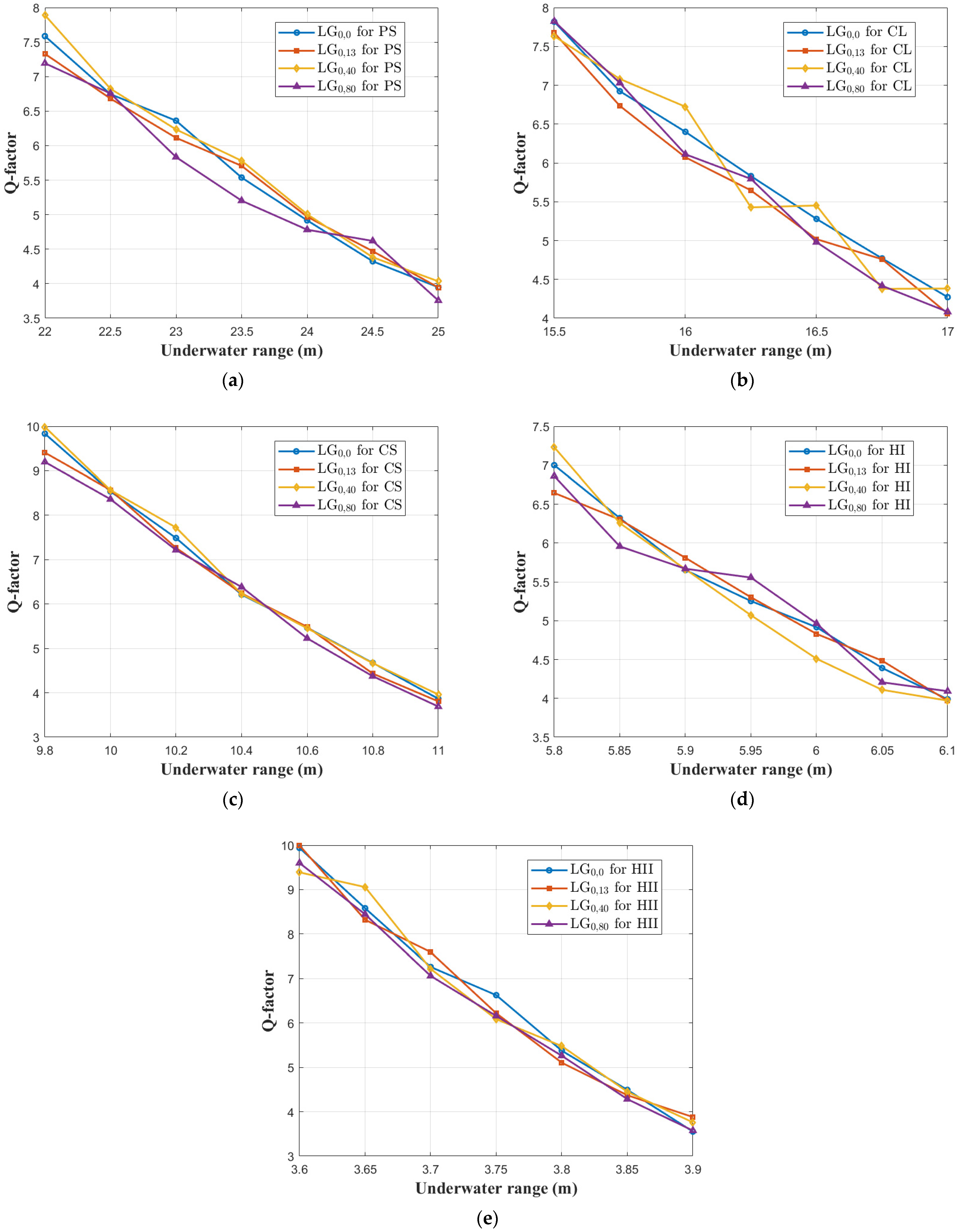
Figure 6 depicts the Q-factor at varying underwater transmission distances in five water bodies for the four OAM beams in the proposed hybrid UOWC/MMF/FSO system. It is observed across all water types that as the transmission distance between the transmitter and receiver increases, the Q-factor deteriorates. For instance, the Q-factor for the
beam decreases from 7.8 to 4 as the underwater transmission span increases from 22 m to 25 m in PS water, as shown in
Figure 6a.
Furthermore, PS water achieves the longest underwater transmission distance with the highest Q-factor due to its low
and
. At a Q-factor of approximately 4, all OAM beams support underwater spans of up to 25 m for PS, 17 m for CL, 11 m for CS, 6.1 m for HI, and 3.9 m for HII, as depicted in
Figure 6a–e, respectively. The shorter underwater spans observed in CS, HI, and HII water types are attributed to the high concentration of dissolved particles in CS and the highest concentrations of suspended and dissolved particles in both HI and HII, resulting in elevated extinction coefficients in CS and the highest extinction coefficient values in HI and HII.
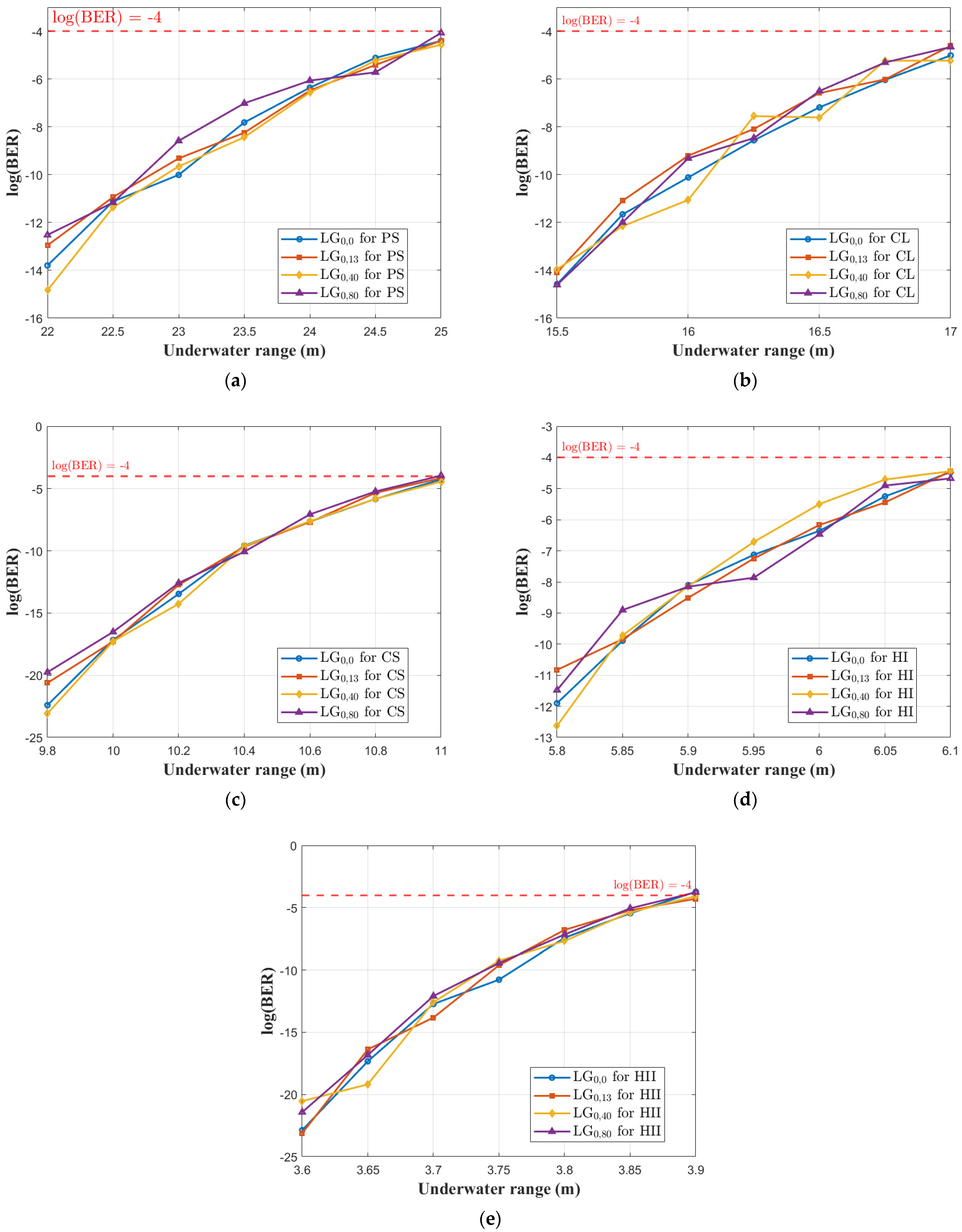
Figure 7 presents the BER performance for the
,
,
, and
modes of the proposed hybrid UOWC/MMF/FSO system in PS, CL, CS, HI, and HII water bodies. The dashed red line, indicating a BER threshold of log(BER) = −4, serves as the upper limit for maintaining reliable communication. The results reveal that log(BER) increases with the underwater transmission distance. Additionally, the inherent attenuation properties of water have an impact on BER performance, which restricts the maximum underwater traveling distance.
Among the water types, PS demonstrates the longest
of 25 m for all OAM beams at log(BER) ~−4, as shown in
Figure 7a. In contrast,
Figure 7e illustrates that HII exhibits the shortest
of 3.9 m (a reduction of 84.4%) for all OAM beams, which is expected due to its highest
and
.
For other water types, the
values achieved by all OAM beams at log(BER) ~−4 are 17 m for CL, 11 m for CS, and 6.1 m for HI, as depicted in
Figure 6b–d, respectively.
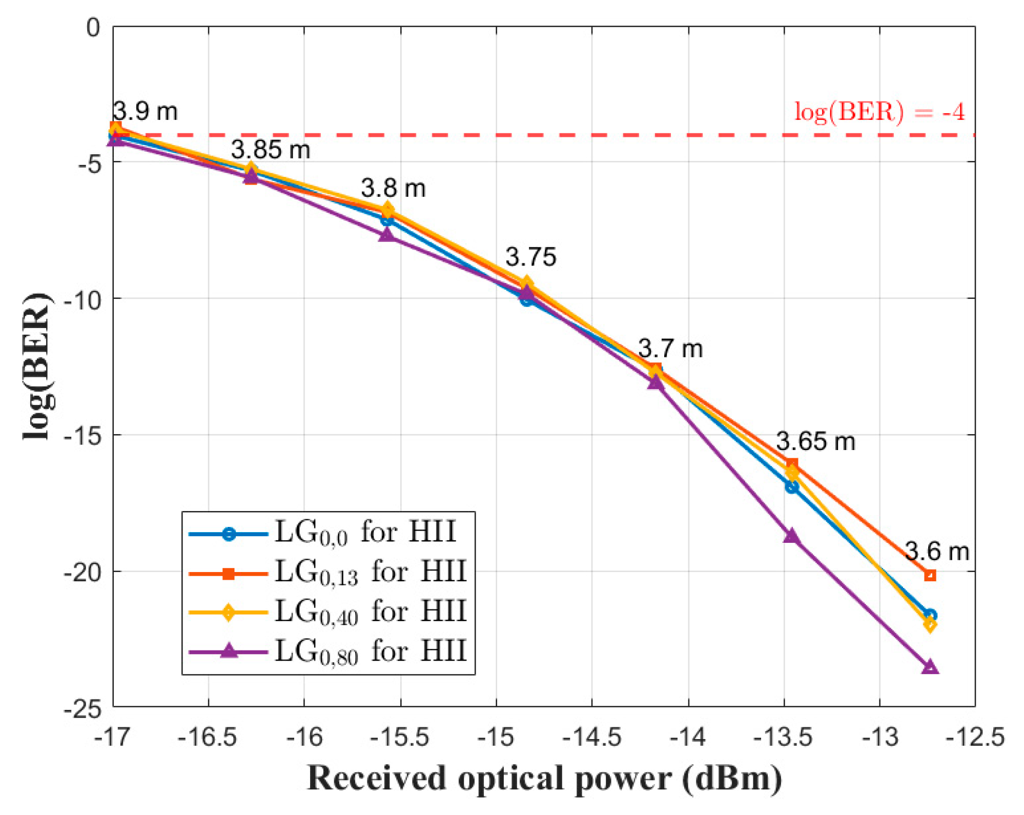
For simplicity, the received optical power for all OAM beams is discussed for the HII water body, as it exhibits the worst performance with the shortest transmission distance.
Figure 8 depicts the received optical power for all OAM beams in the HII water body. The results indicate that as the received optical power increases, the log(BER) decreases. Furthermore, the received optical power is higher at shorter underwater transmission distances and decreases with increasing distance. For instance, the
beam exhibits a received optical power of −12.7 dBm at a transmission distance of 3.6 m, which decreases to −17 dBm when the transmission distance extends to 3.9 m.
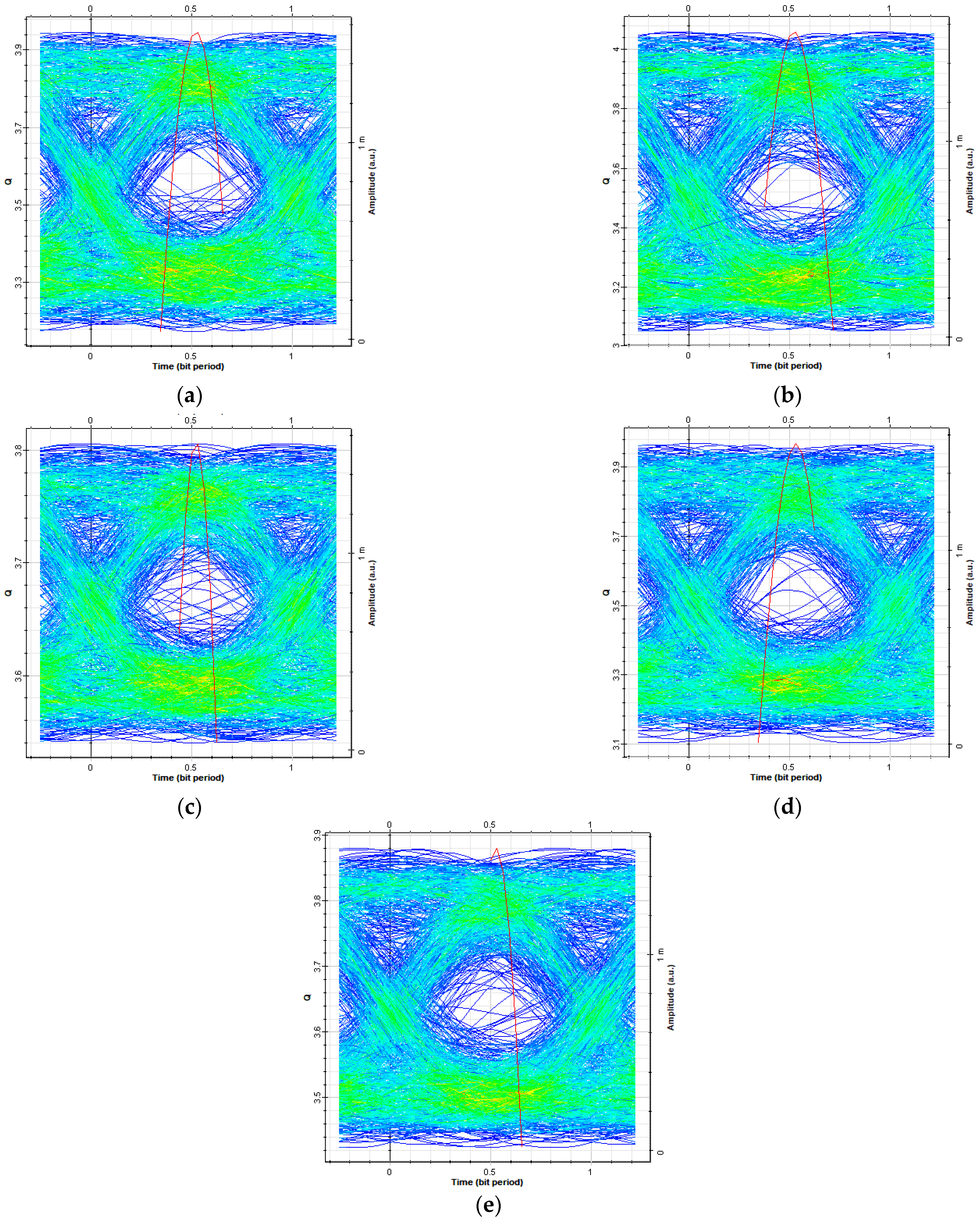
Since all OAM beams exhibit nearly identical performance at 25 m for PS, 17 m for CL, 11 m for CS, 6.1 m for HI, and 3.9 m for HII, for simplicity, the eye diagrams for a single OAM beam, specifically
, at these underwater transmission ranges are shown in
Figure 9. Although the eye openings are not particularly wide, their presence indicates that the transmitted data are successfully received at these ranges.
Finally, the overall transmission distances achieved through the hybrid channels by all OAM beams for different types of waters in the proposed system, with a log(BER) of approximately −4, a Q-factor of nearly 4, a received optical power of −17 dBm, and overall transmission capacity of 20 Gbps, are summarized in
Table 4.
5.2. System Performance Evaluation: Fixed 20 m UOWC Link (PS Water) and 100 m MMF, Variable FSO Range in Foggy Conditions
In this subsection, the proposed hybrid UOWC/MMF/FSO system is assessed by examining the received optical power, Q-factor, BER, and eye diagrams for four OAM beams across five distinct water types. The analysis considers a fixed UOWC link spanning 20 m in PS water and an MMF segment of 100 m. The presented results highlight the system’s performance across varying FSO propagation distances under different foggy weather conditions. Additionally, the overall transmission capacity considered is 20 Gbps.
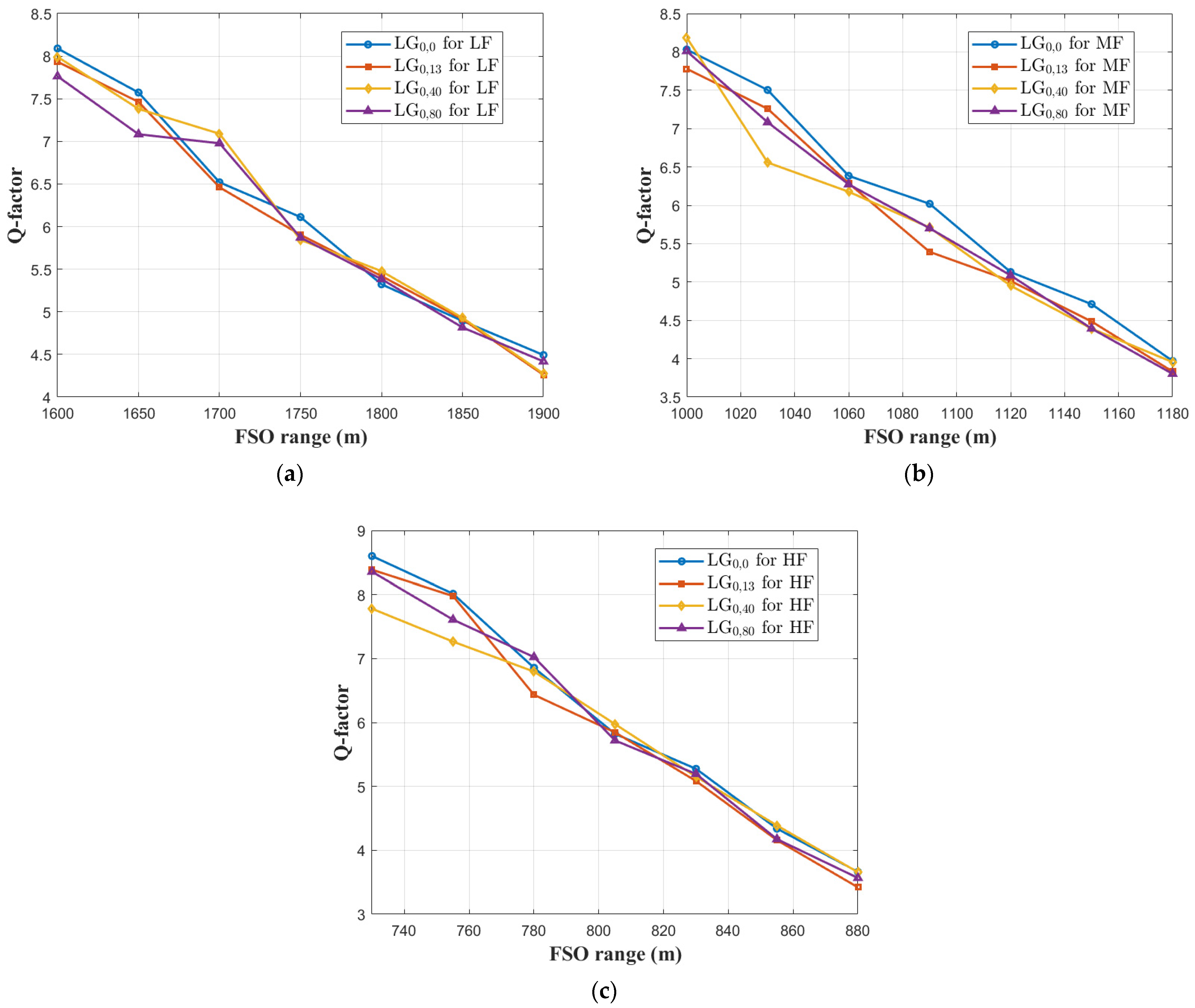
Figure 10 depicts the Q-factor performance for the four OAM beams of the proposed hybrid UOWC/MMF/FSO system under three levels of fog conditions. One can observe that the Q-factor decreases as the FSO propagation range increases, a trend observed consistently across all OAM beams and fog levels (LF, MF, and HF). This decline is attributed to the impact of atmospheric attenuation on the FSO propagation range, which limits the achievable FSO distance.
In LF, the system supports longer FSO ranges, extending up to 1900 m, with a relatively gradual degradation in Q-factor, and that is clear from
Figure 10a. Conversely, under MF (
Figure 10b), the FSO range is limited to 1180 m due to higher attenuation levels, resulting in a more pronounced decline in Q-factor. Finally, it can be seen from
Figure 10c that the HF condition demonstrates the most severe impact, with the FSO range restricted to 880 m, because of its highest attenuation. Nevertheless, in all cases, the Q-factor remains above the threshold for reliable communication (approximately 4) within the respective ranges. Furthermore, the four OAM beams exhibit nearly identical performance across all fog conditions, demonstrating the robustness of the proposed hybrid system in supporting multiple OAM beams while maintaining acceptable transmission quality under varying atmospheric conditions.
Figure 11 demonstrates the BER performance for four OAM beams (
,
,
, and
) of the proposed hybrid UOWC/MMF/FSO system at an overall transmission capacity of 20 Gbps. The analysis is carried out under three distinct fog conditions: LF, MF, and HF. The dashed red line at log(BER) = −4 indicates the BER threshold required for reliable communication. As observed from the results, log(BER) increases (indicating degraded performance) as the FSO propagation range increases, which is consistent across all OAM beams and fog conditions. However, as the level of fog intensifies, the information signal is propagated over shorter ranges, which can be attributed to the increased atmospheric attenuation. Considering the same weather condition as an example, MF, it is observed from
Figure 11b that the log(BER) increases from −15.2 to −4.1 (a degradation of 73.03%) for the
mode as the transmission distance between the transmitter and receiver extends from 1000 m to 1180 m. For LF and HF conditions, all OAM beams support FSO propagation ranges of up to 1900 m and 880 m, respectively, as shown in
Figure 10a and
Figure 11c. These ranges are observed to be below the threshold (at log(BER) = −4).
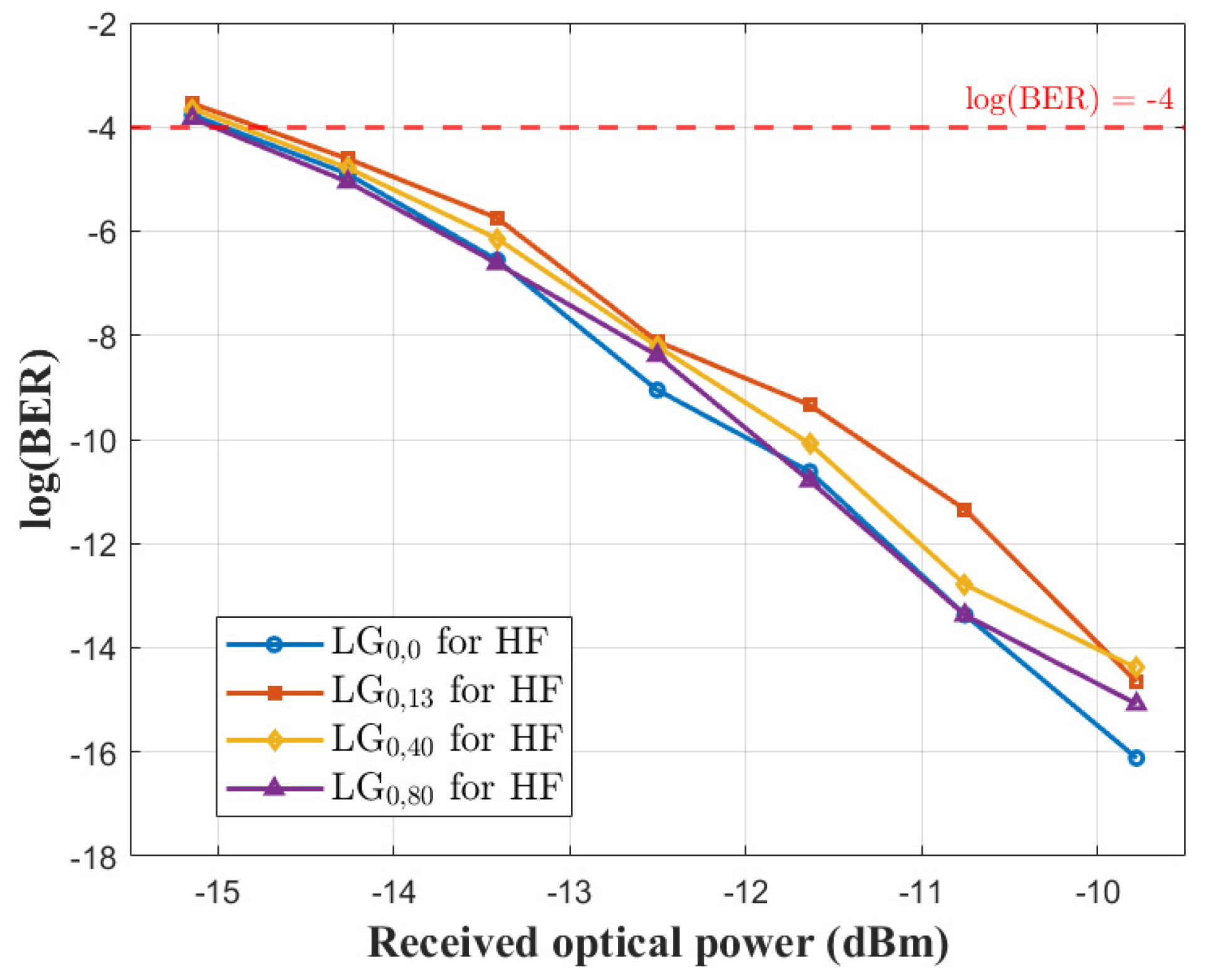
For clarity, the received optical power for all OAM beams is analyzed under the HF condition, which presents the least favorable performance and the shortest FSO span.
Figure 12 demonstrates the received optical power for all OAM beams under the HF condition. The results reveal that an increase in received optical power corresponds to a decrease in log(BER). Additionally, the received optical power is greater at shorter FSO propagation ranges and diminishes as the range increases. For example, the
shows a received optical power of −9.7 dBm at an
of 730 m, which drops to −15.1 dBm as the
extends to 880 m.
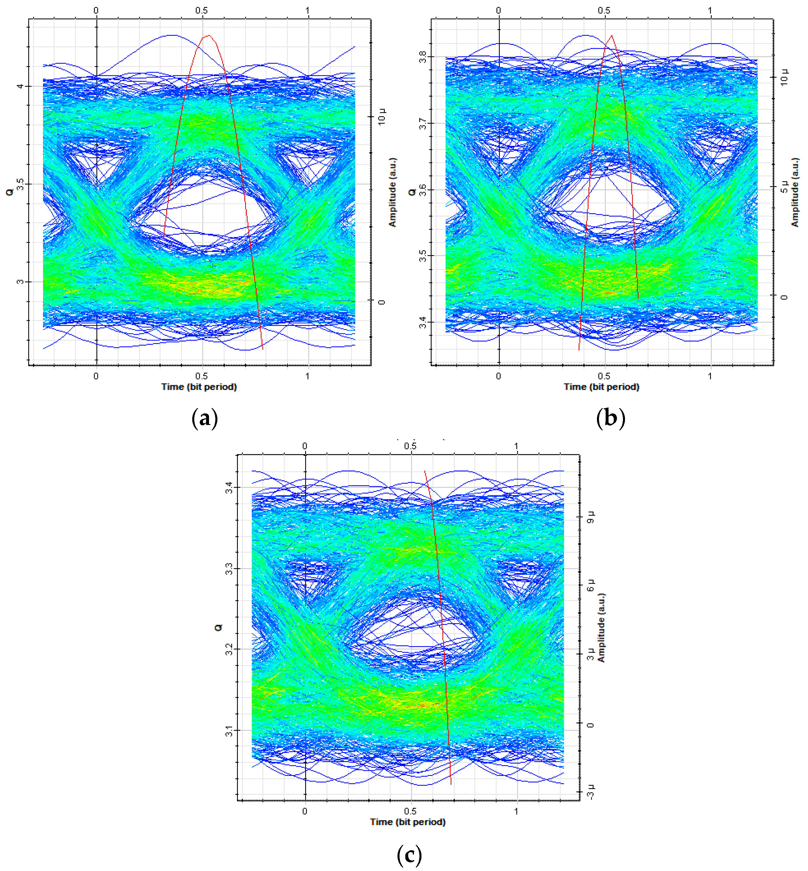
Due to the nearly identical performance observed across all OAM beams at 1900 m for LF, 1180 m for MF, and 880 m for HF, the eye diagrams for a representative OAM beam, specifically
, are shown in
Figure 13, for simplicity at these FSO ranges. While the eye openings are relatively narrow, their existence confirms the successful reception of the transmitted data at these ranges.
Table 5 tabulates the overall transmission distances for the proposed hybrid system under foggy weather conditions with an overall transmission capacity of 20 Gbps at log(BER), Q-factor, and received optical powers of approximately −4, 4, and −15.1 dBm, respectively.
Table 6 provides a comparative analysis of previous studies employing hybrid optical communication channels and the proposed hybrid system. While some prior models demonstrated superior performance in terms of overall transmission distance or capacity, these models were limited to the use of two optical channels. In contrast, the proposed system utilizes three optical channels, offering a more robust framework. The main innovation lies in the integration of three distinct optical communication channels (UOWC, MMF, and FSO) into a single hybrid framework. This triple-channel architecture offers a more comprehensive and flexible solution than previous models that typically utilized only two channels. Furthermore, we uniquely incorporate realistic environmental conditions by evaluating the system performance across five types of water and three levels of fog, enabling a more practical assessment of the system’s applicability in diverse operational scenarios. The proposed system employs OAM-based multiplexing with OOK-NRZ modulation, allowing enhancement in transmission capacity. In addition, we utilize PRFR across the links to facilitate signal conversion and reliable data transmission between channels operating in different spectral bands. Despite employing only a single wavelength, our system achieves a transmission capacity of 20 Gbps and supports extended communication distances even under high-attenuation conditions, demonstrating greater spectral efficiency and robustness compared to systems that require multiple wavelengths. Additionally,
Table 6 outlines the multiplexing techniques used, number of wavelengths required, modulation schemes employed, environmental conditions considered, and the resulting performance metrics in terms of overall transmission distance and capacity, highlighting the advantages of our proposed approach.
6. Conclusions
In this study, a high-speed hybrid UOWC/MMF/FSO system utilizing OAM beams is proposed for the first time. A PRFR is employed to convert the wavelength from 532 nm, used in the UOWC link, to 1550 nm for implementation in the MMF/FSO link. Four OAM beams, namely , , , and , are used, with each beam carrying data at a rate of 5 Gbps. The performance of the proposed hybrid system is evaluated under two scenarios. In the first scenario, the impact of water absorption and scattering coefficients of five water types on the underwater transmission distance is analyzed, while maintaining a constant MMF length of 100 m and an FSO link range of 1000 m under clear weather conditions. In the second scenario, PS water with an underwater transmission distance of 20 m and a fixed MMF length of 100 m is considered, with varying FSO propagation ranges under three different fog conditions characterized by distinct atmospheric attenuation levels. The system’s performance is evaluated to ensure a BER ≤ 10−4 and a Q-factor of approximately 4, guaranteeing reliable communication. The findings from the first scenario indicate that water attenuation significantly impacts the underwater transmission distance. For example, HI water, with higher absorption and scattering coefficients, limits the total transmission range to 1103.9 m (comprising a 3.9 m UOWC link, 100 m MMF link, and 1000 m FSO range). In contrast, this range is extended to 1125 m (25 m UOWC link + 100 m MMF length + 1000 m FSO range) in PS water, which exhibits the lowest attenuation among the considered water types. Additionally, the received optical power is influenced by the transmission distance, decreasing as the distance increases. For instance, in HII water, the received power is −17 dBm at a total transmission range of 1103.9 m.
In the second scenario, atmospheric attenuation due to fog conditions restricts the transmission range. The longest total range of 2020 m (20 m UOWC link + 100 m MMF length + 2000 m FSO range) is achieved under LF conditions. This range decreases to 1300 m for MF conditions and is further reduced to a minimum of 1000 m under HF conditions. Furthermore, atmospheric attenuation also affects the received optical power, with degradation observed as the transmission distance increases.
The proposed terrestrial hybrid system is suggested for IoUT applications that require efficient data exchange between underwater nodes and base stations.
As part of our future work, we plan to investigate the effects of underwater and atmospheric turbulence on the performance of the hybrid UOWC/MMF/FSO system. Additionally, we aim to integrate advanced multiplexing techniques to further enhance the overall transmission capacity. The impact of practical impairments associated with non-ideal OAM multiplexers and selectors including insertion loss, mode crosstalk, and misalignment will also be evaluated to provide a more realistic assessment of system performance and hardware feasibility. Furthermore, we intend to explore the propagation of higher-order OAM beams in realistic MMF structures by considering critical parameters such as core–cladding refractive index differences, index profiles, and mode coupling effects. In particular, the feasibility of preserving OAM mode integrity over longer distances will be examined using graded-index and ring-core MMFs, which are specifically designed to support stable OAM propagation.

 ,
, 

