Article

Waveguide Coupled Full-Color Quantum Dot Light-Emitting Diodes Modulated by Microcavities

1
College of New Materials and New Energies, Shenzhen Technology University, Shenzhen 518118, China
2
Department of Electronic and Electrical Engineering, Institute of Nanoscience and Applications, Southern University of Science and Technology, Shenzhen 518055, China
3
State Key Laboratory of Bio-Fibers and Eco-Textiles, Qingdao University, Qingdao 266071, China
*
Authors to whom correspondence should be addressed.
These authors contributed equally to this work.
Photonics 2025, 12(5), 427; https://doi.org/10.3390/photonics12050427
Submission received: 11 March 2025 / Revised: 23 April 2025 / Accepted: 24 April 2025 / Published: 29 April 2025
(This article belongs to the Special Issue Quantum Dot Light-Emitting Diodes: Innovations and Applications)

Abstract

:
Integrated light-emitting diodes (LEDs) with waveguides play an important role in applications such as augmented reality (AR) displays, particularly regarding coupling efficiency optimization. Quantum dot light-emitting diodes (QLEDs), an emerging high-performance optoelectronic device, demonstrate substantial potential for next-generation display technologies. This study investigates the influence of microcavity modulation on the output of QLEDs coupled with a silicon nitride (SiNx) waveguide by simulating a white light QLED (W-QLED) with a broad spectrum and mixed RGB QDs (RGB-QLED) with a comparatively narrower spectrum. The microcavity converts both W-QLED and RGB-QLED emissions from broadband white-light emissions into narrowband single-wavelength outputs. Specifically, both of them have demonstrated wavelength tuning and full-width at half-maximum (FWHM) narrowing across the visible spectrum from 400 nm to 750 nm due to the microcavity modulation. The resulting RGB-QLED achieves a FWHM of 11.24 nm and reaches 110.76% of the National Television System Committee 1953 (NTSC 1953) standard color gamut, which is a 20.95% improvement over W-QLED. Meanwhile, due to the Purcell effect of the microcavity, the output efficiency of the QLED coupled with a SiNx waveguide is also significantly improved by optimizing the thickness of the Ag anode and introducing a tilted reflective mirror into the SiNx waveguide. Moreover, the optimal output efficiency of RGB-QLED with the tilted Ag mirror is 10.13%, representing a tenfold increase compared to the sample without the tilted Ag mirror. This design demonstrates an efficient and compact approach for the near-eye full-color display technology.

1. Introduction

The integration of light-emitting diodes (LEDs) with waveguides plays an important role in emerging display technologies, particularly in augmented reality (AR) applications, where efficient light coupling is critical for achieving high-performance compact displays [1,2]. Traditional GaN-based micro-LEDs, while widely used in AR displays, face inherent limitations in achieving strong microcavity effects due to their thick n-GaN layers (typically several micrometers) [3,4,5], which hinder precise optical mode control. In contrast, quantum dot light-emitting diodes (QLEDs) have emerged as a promising candidate for next-generation displays due to their narrow bandwidth, tunable emission colors, high color purity, thin-film structure, and cost-effective solution processability, which provide a unique opportunity to integrate microcavity structures [6,7,8,9]. Despite these advantages, the integration of QLEDs with waveguides remains underexplored. Current research has primarily focused on external light coupling [10,11,12], with limited attention given to the role of microcavity effects in optimizing emission properties after coupling to the silicon nitride (SiNx) waveguides, which is the focus of this work.
Optical microcavities primarily comprise ultra-thin semiconductor laminated structures sandwiched between two special reflective surfaces, significantly modifying the density of optical modes compared to free space [13,14]. This is one of the key tools for improving emission properties [15,16]. It has been demonstrated that microcavities can be integrated with QLEDs to narrow the full-width at half-maximum (FWHM) bandwidth and improve the output efficiency of the device [17]. This is realized by confining light within the designed space and enabling constructive interference. The microcavity can then selectively enhance specific optical modes while suppressing the others, leading to precise spectral control [18,19]. It also facilitates efficient light extraction by directing emitted light into the desired modes and minimizing energy losses [20]. This inspired the idea to rationalize adjustment of the microcavity to achieve spectral modulation, FWHM bandwidth narrowing, and improved output efficiency, thereby enabling the development of novel full-color QLED on-chip light sources.
Waveguides confine and direct light within a defined path through total internal reflection (TIR). In recent years, widely reported and investigated QLEDs have demonstrated that integration with waveguides potentially generates various important applications in integrated display technologies [21,22,23]. By integrating QLEDs and waveguides on the same chip, it is possible to achieve highly integrated optoelectronic devices [24]. This integration utilizes the high refractive index of waveguides to confine light within a sub-wavelength range. Such configurations not only reduce the bulkiness of traditional displays but also maintain high emission properties. While existing research has primarily focused on how to couple the external light sources to the waveguides [25], there has been limited exploration of the methods and measures for the emission properties of QLED after waveguide coupling.
This study investigates the influence of microcavity modulation on the performance of light sources coupled with SiNx waveguides through adjusting the thickness and reflectivity of the spacer and electrode. Since the microcavity could modulate the emission from broadband white light to narrowband single-wavelength output, two models with different original emission spectra, a broad-spectrum white light QLED (W-QLED) and narrow-spectrum mixed RGB QDs (RGB-QLED) coupled with SiNx waveguides, are established. Due to the microcavity effect, the thickness and reflectivity of the spacer and electrode significantly influence the wavelength tuning, the linewidth narrowing of FWHM, and the angular distribution of emission intensity. Moreover, the output efficiency at the SiNx waveguide is further enhanced by a tilted Ag mirror. By investigating microcavity modulation, this research may offer a new route for advancements in the efficiency and color quality improvement of the on-chip light source.

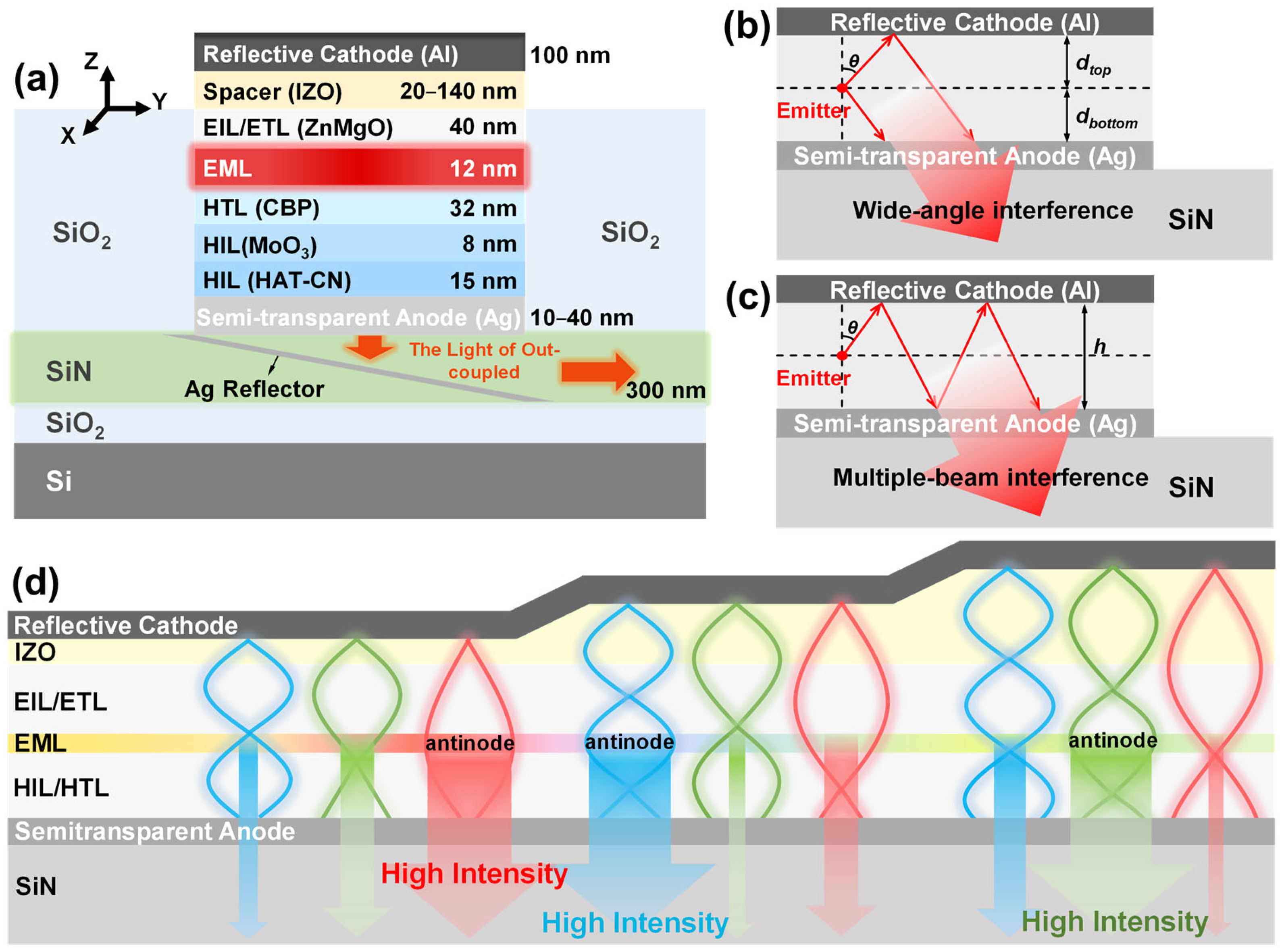
2. Theoretical Approach

As shown in Figure 1a, the design consists of Si substrate/SiNx (300 nm)-on-SiO2/semi-transparent Ag (varying from 10 nm to 40 nm)/1,4,5,8,9,11-Hexaazatriphenylene hexacarbonitrile (HAT-CN) (15 nm)/MoO3 (8 nm)/4,4′-Bis (N-carbazolyl)-1,1′-biphenyl (CBP) (32 nm)/the emitting layer (EML) (12 nm)/ZnMgO (40 nm)/indium zinc oxide (IZO, varying from 20 nm to 140 nm)/Al (100 nm), wherein the second transparent insulating layer SiO2 as a protective layer is extended from the SiNx waveguide to the lower surface of the IZO spacer layer. The hole injection layers (HILs) are composed of HAT-CN and MoO3. The CBP and ZnMgO layer are employed as the hole transport layer (HTL) and the electron transport layer (ETL), respectively. Ag serves as the semi-transparent anode, Al functions as the top reflective cathode, and IZO is inserted between the reflective cathode and the ETL as a spacer to adjust the microcavity length. The EML could use active layer materials such as CdSe/ZnS QDs. There is a radiative recombination of electrons and holes in the EML, which leads to light emission. The emitted light then passes partly through the semi-transparent Ag anode and couples into the SiNx waveguide. The microcavity within this design is built between the semi-transparent Ag anode and the top reflective Al cathode, including the HIL, HTL, EML, EIL/ETL, and IZO spacer layers. The optical microcavity structure, consisting of two reflective metal electrodes and a sandwiched emissive layer, is based on the concept introduced by Bulović et al. in 1998 [26]. The complete material selection and structure are designed according to a conventional QLED [27].
The light emitted from the EML undergoes reflection and transmission leading to wide-angle interference and multiple-beam interference in the microcavity. Wide-angle interference refers to the interference between the light emitted from the EML and that reflected once from either the bottom or top metal electrode layer [28]. As depicted in Figure 1b, the light emitted by the EML and the light reflected by the top Al cathode will be transmitted into the waveguide after wide-angle interference. Multiple-beam interference occurs due to multiple reflections between the top and bottom electrodes and is closely related to the length of the microcavity [29]. As depicted in Figure 1c, the emitted light experiences repeated reflections within the microcavity, forming a coherence stack and then being transmitted into the waveguide. The wide-angle and multiple-beam interference resonant condition of the microcavity can be mathematically described as follows [30,31]:
4 π h λ cos θ φ top φ bottom = 2 π m 1
4 π d t o p ( b o t t o m ) λ cos θ φ t o p ( b o t t o m ) = 2 π m 2
φ = arctan 2 n 0 k m n 0 2 n m 2 k m 2
h = j n j d j
where φtop(bottom) is the phase shift at the top Al electrode or bottom Ag electrode, dtop(bottom) is the optical thickness between the EML and the top Al or bottom Ag electrode, θ is the angle of incidence, m is the order of resonance which is an integer, n0 is the effective refractive index of functional layers from the EML to the top or bottom electrode, nm and km are the real and imaginary parts of the refractive index of the metal electrode, and nj and dj are the refractive index and thickness of the functional layers within the microcavity. Equation (1) represents multiple-beam interference, with wide-angle interference as a special case that can be described by Equation (2). The phase shift φ at the reflective electrode can be obtained by Equation (3). The optical thickness h of the microcavity can be given by Equation (4), and dtop(bottom) can be obtained similarly.
It can be seen that interference enhances emission only when the emission wavelength satisfies Equation (1) or Equation (2). Therefore, the appropriate microcavity thickness is particularly important for modulating the resonant wavelength. According to Fresnel laws [32], the reflectivity at the interfaces between the top and bottom electrodes and their adjacent functional layers can be calculated as highly dependent on the refractive indices of the materials. The calculation results indicate that the top interface exhibits a higher reflectivity leading to a more pronounced modulation effect. Therefore, an IZO spacer is placed between the ETL and the top Al cathode to adjust the dtop. It is worth mentioning that variations in the thickness of the IZO spacer have a negligible effect on the reflectance and transmittance in the visible spectrum [33], which makes it more suitable for tuning the resonant wavelength. By changing the thickness of IZO, the optical thickness of the microcavity can be effectively adjusted, enabling precise control of the emission resonant wavelength [34].
Additionally, Figure 1d illustrates a schematic of the R, G, and B emission resonance within the microcavity-waveguide structure as the variation of the IZO thickness. It is evident that adjusting the thickness of the IZO layer alters the distance between the EML and the reflective electrode. Consequently, the microcavity can be used to selectively filter different colors of light. Furthermore, as the thickness of the IZO layer increases, the resonant wavelength emitted from the SiNx waveguide shifts from red light to blue light and then to green light, with the optimal emitter located at the antinodes of the resonance wave.
Narrowing of the spectral bandwidth is another favorable property of microcavity modulation. The Δλ describes the broadening of the resonant wavelength of the microcavity itself, which is used to evaluate how sharp the resonance of the microcavity is [35,36], where λ is the targeted resonant wavelength of the emitted light, R1 and R2 are the reflectivity at the top and bottom interfaces, and L is the effective microcavity length that can be given by Equation (6). This expression is derived from the theory of the Fabry–Pérot resonator and represents the microcavity’s own spectral filtering characteristics, determined solely by physical parameters such as the microcavity length, effective refractive index, resonant wavelength, and microcavity reflectivity.
Δ λ = λ 2 2 π L ( 1 R 1 R 2 ) R 1 R 2 4
L = j n j d j cos θ + φ t o p λ 4 π λ + φ b o t t o m λ 4 π λ
From Equations (5) and (6), it can be seen that as R1 and R2 increase, the Δλ bandwidth becomes narrower [37]. To ensure sufficient light is reflected back into the microcavity by the top cathode and subsequently transmitted to the SiNx waveguide, an electrode with high Al thickness (100 nm) and high reflectivity is installed [38]. This is because although the reflectivity of Al changes with increasing thickness, it attains a saturation limit beyond which further increases in thickness do not enhance reflectivity. Therefore, the narrowing of the Δλ bandwidth is modulated only by the bottom Ag electrode. Research indicates that an increase in the thickness of the Ag anode enhances its reflectivity [39], leading to reduced Δλ bandwidth and improved quality of light reflection within the microcavity. This enhancement fosters stronger multiple-beam interference and strengthens the optical selectivity of the microcavity, resulting in sharper and more concentrated spectral peaks. It is important to note that Equations (5) and (6) describe the intrinsic spectral bandwidth of the optical microcavity, determined solely by its physical parameters and independent of the emission characteristics of the EML. The simulated FWHM of the QLEDs results from the combined effect of the microcavity modulation and the intrinsic spectrum of the EML. The detailed derivation of Equation (5) is shown in Supplementary S1. To simulate the light emission within the EML, oscillating dipoles are introduced based on the model of Chance, Prock, and Sibley (CPS) theory [40]. Since the light emitted from dipoles is isotropic, three oscillation directions along the x, y, and z axes are used to simulate the real light emission. These correspond to orientations of 0°90°0° along the x-axis, 0°90°90° along the y-axis, and 0°0°0° along the z-axis. These three degrees refer to the phase, theta, and phi in the FDTD simulation.
In the proposed configuration, light emitted from the Ag anode enters the SiNx waveguide and transmits along the waveguides with various loss mechanisms, leading to a decrease in output efficiency. To improve the output efficiency, a tilted reflective Ag mirror is introduced into the SiNx waveguide [41,42,43]. The tilted mirror is positioned at 45° to direct the light efficiently along the waveguide. In this context, the waveguide output efficiency is a key parameter that determines how effectively light emitted from the QLED is coupled into and transmitted through the waveguide. This efficiency is defined as the average output efficiency across three orthogonal oscillation directions:
T n = E o u t p u t E e m i s s i o n
T a v e r a g e = T x + T y + T z 3
where Tn is the output efficiency at the end of the waveguide (positioned at 50 μm) for a dipole oscillating along a single direction (x, y or z), Eoutput is the output light energy of the waveguide, Eemission is the light energy emitted by the EML, and the average output efficiency Taverage of the three oscillation directions (x, y and z) is taken as the output efficiency at the end of the waveguide.
The Setfos simulation software (Fluxim 5.0) was employed to investigate the effects of microcavity modulation on the emission properties of QLED, such as wavelength tuning, FWHM bandwidth narrowing, and emission angle distribution. Additionally, to achieve an optimal balance between FWHM bandwidth and output efficiency, finite difference time domain (FDTD) simulations were performed using Lumerical’s commercial software package (Ansys Optics 2023 R1). The complex refractive indices (n: refractive index, k: extinction coefficient) of all materials used in simulations are provided in Appendix A. In both Setfos and Lumerical FDTD, W-QLED and RGB-QLED were constructed by establishing nanoscale thin films corresponding to the thicknesses and refractive indices of predetermined materials. For the W-QLED, the EML can be constructed by applying the full OLED-white spectrum from the database in Setfos, which exhibits an isotropic emission spectrum covering the visible range from 380 nm to 780 nm. Here, the ‘Q’ in W-QLED specifically refers to the QDs-derived refractive index and structural parameters of the EML, rather than the emission spectrum itself. Therefore, the matched optical properties enable the simulation to focus solely on how different spectra propagate, couple or modulate under the influence of a microcavity. For the RGB-QLED, the EML was designed based on a specific material composition to emit an equal-energy white light. This study employs a blend of red, green, and blue CdSe/ZnS QDs with a mass ratio of 1:4:17 as the EML, which exhibits the International Commission on Illumination (CIE) color coordinates of (0.28, 0.36) [17]. The result shows that this composition has a minimal deviation from the position of the equal-energy white light on the 1931 CIE color coordinate system.

3. Numerical Results and Discussion

This study investigates the influence of microcavity modulation on the emission properties of QLEDs with different original emission spectra and the output efficiency from the waveguide. The emission properties of microcavity modulated QLED were examined with a focus on the effects on wavelength tuning, FWHM bandwidth narrowing, and emission angular distribution.

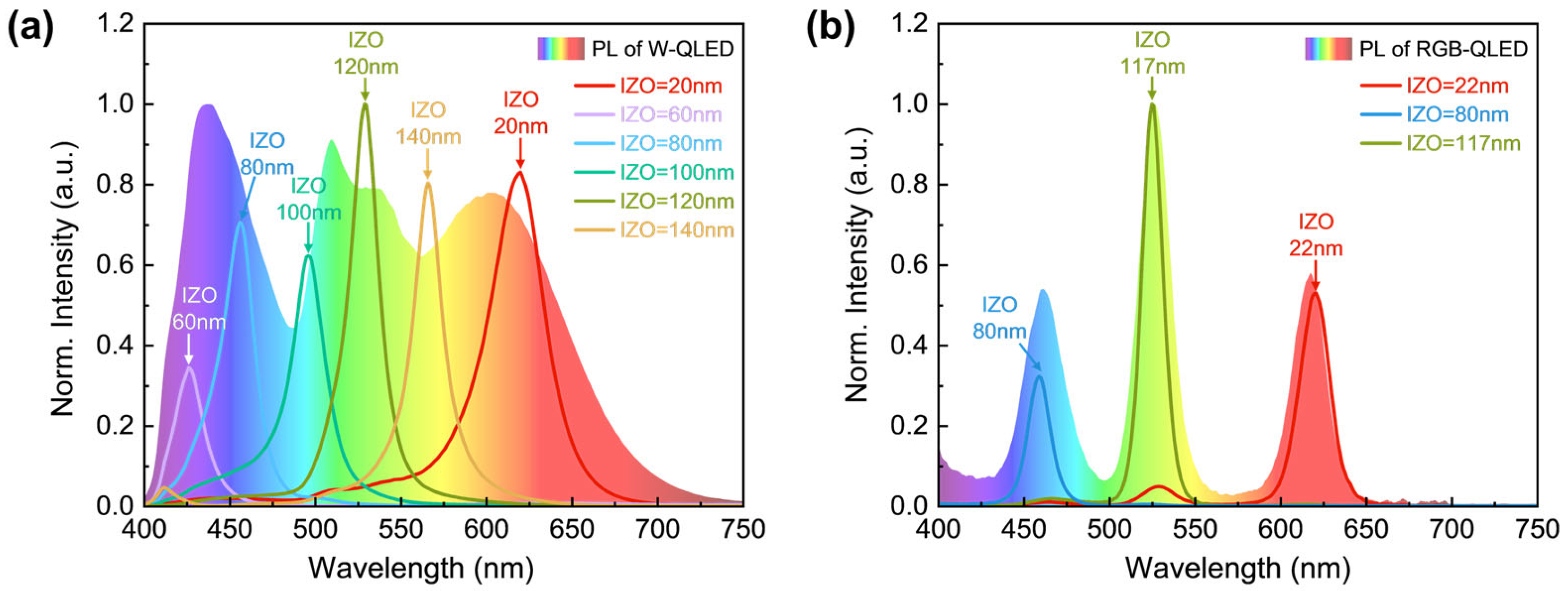
3.1. Spectral Tunability for QLED Coupled with SiNx Waveguide

To explore spectral tunability, the optical model of QLED with tunable IZO thickness is developed. The initial emission spectra of W-QLED and RGB-QLED exhibit distinct characteristics due to their different compositions. The W-QLED features a broad emission spectrum, which is simulated to intuitively demonstrate that the microcavity effect via the IZO spacer can be applied across the visible spectrum from 400 nm to 750 nm. In contrast, the RGB-QLED consists of separate red, green, and blue emissions with intrinsically strong emission at specific wavelengths. The microcavity effect, introduced by the IZO spacer, significantly influences the spectral emission of both samples by transforming broadband white-light emissions into narrowband, single-wavelength outputs. The simulation firstly focuses on the emission spectral property of the waveguide. Figure 2a illustrates the spectral tunability of the W-QLED as the IZO thickness varies at an Ag anode of 30 nm. As the IZO thickness increases from 20 nm to 140 nm, the emission peak shifts across the visible spectrum from 400 nm to 750 nm. Specifically, IZO thicknesses of 20 nm, 118 nm, and 82 nm correspond to emission peaks at 620 nm (red), 525 nm (green), and 460 nm (blue), respectively. These wavelengths align with the intrinsic high-intensity emission peaks of the QD layer in the RGB-QLED, making them optimal for contrasting the spectral emissions. Similar spectral tunability is observed in the RGB-QLED, as illustrated in Figure 2b. Under the same Ag anode thickness and emission peaks, the corresponding IZO thicknesses for the RGB-QLED are 22 nm, 117 nm, and 80 nm, respectively. Regardless of whether the original emission spectrum is broad or narrow, the specific emission wavelength could be modulated by the microcavity through adjustments to its length.

3.2. The FWHM Bandwidth Narrowing for QLED Coupled with SiNx Waveguide

Adjusting the Ag anode thickness in the microcavity enhances its reflectivity [39], reduces transmission losses (but also reduces the output efficiency of the waveguide), and strengthens multiple-beam interference. This confines the emission spectrum to a narrower range, sharpens the resonance peak, and thereby improves color selectivity.
The FWHM of the spectra of W-QLED and RGB-QLED with different Ag anode thicknesses are analyzed. Both samples show a narrowing of FWHM with increasing Ag thickness. A comparison of the Δλ based on Equation (5) and the simulated FWHMs is provided in Table S1. The W-QLED was initially simulated to demonstrate how the microcavity can modulate a wide-spectrum emission to a spectrally selected and narrow emission. Because of its inherently broad spectrum, the transition from broadband to narrowband emission is clearly shown in Figure 3a. It shows the spectra of green light emitted at 525 nm by the W-QLED, where the IZO thickness is 118 nm and the Ag anode thickness varies from 10 nm to 40 nm, corresponding to an increase in reflectivity from 35% to 93.5% [39]. The results reveal a significant narrowing of the FWHM from 56.79 nm to 15.52 nm as the Ag thickness increases, leading to the enhanced reflectivity of the Ag layer, which strengthens multiple-beam interference. Figure 3b provides the FWHM results for the RGB-QLED with the IZO thickness of 117 nm under the same Ag thicknesses variation range. Compared to the W-QLED, the RGB-QLED achieves much narrower FWHMs across all Ag thicknesses, with the FWHM decreasing from 17.82 nm to 11.24 nm as the Ag thickness increases. Additionally, both the W-QLED and the RGB-QLED will reduce the emission intensity due to the surface plasmon polariton (SPP) mode.
The red, green and blue spectral properties between two samples emitted at 620 nm, 525 nm, and 460 nm are further compared, as shown in Figure 3c. For red light with the Ag thickness of 30 nm, RGB-QLED achieves the FWHM of 20.72 nm and W-QLED exhibits the FWHM of 40.69 nm. For green light with the Ag thickness of 32 nm, FWHMs of RGB-QLED and W-QLED are 14.39 nm and 21.17 nm, respectively. For blue light with the Ag thickness of 36 nm, FWHMs are 15.4 nm for RGB-QLED and 19.87 nm for W-QLED. The Ag thickness used is not the one corresponding to the narrowest FWHM, but rather the Ag thickness at which both RGB-QLED and W-OLED exhibit their maximum emission intensity. This value happens to be the same for both QLEDs. In comparison, the RGB-QLED achieves significantly narrower FWHMs under the same Ag thicknesses, indicating that the RGB-QLED offers more superior spectral refinement. This is primarily attributed to the narrower PL spectrum of QDs and enhanced microcavity resonance. As the Ag anode thickness increases, the reflectivity rises, which effectively narrows the Δλ. In RGB-QLEDs, where red, green, and blue emissions originate from spectrally narrow and well-separated bands, the high-reflectivity microcavity more precisely reinforces individual resonant modes and suppresses sideband emissions. On the contrary, in W-QLEDs, which rely on broadband white emitters, the same narrowing cannot be achieved due to intrinsic spectral overlap. Therefore, narrower FWHMs are more pronounced in RGB-QLEDs across all wavelengths. According to Equation (5), the influence of λ on the Δλ increases as the wavelength redshifts, resulting in an inherently broader FWHM of red light than that of blue and green light. Therefore, the W-QLED shows a notably broader FWHM of red light compared to green and blue, while the RGB-QLED maintains consistently narrow FWHMs across all wavelengths. The optimized Ag thickness for each wavelength further highlights the advantages of effective microcavity modulation in achieving high spectral finesse and color purity, particularly in the RGB-QLED.
By altering the thickness of the semitransparent Ag anode and IZO spacer simultaneously, it is possible to achieve variations in the emitted light color and the FWHMs of the specific wavelength, as shown in Figure 3d. As discussed before, the IZO layer plays a crucial role in determining the color of the emitted light by modulating the optical path length within the microcavity. Although both samples demonstrate tunable spectral properties, the RGB-QLED outperforms the W-QLED in terms of color purity, as shown in Figure 3e due to the narrower FWHMs in a given wavelength. Therefore, the narrow emission bandwidth of RGB-QLED enables high-purity emission and achieves better color saturation.
Based on the emission spectra in Figure 3c, CIE color diagrams can be plotted. Figure 3f provides a quantitative comparison of the color gamut for both samples against the standard gamut, including the National Television System Committee 1953 (NTSC 1953), standard Red Green Blue (sRGB), and Adobe RGB. The W-QLED achieves a color gamut covering 89.81% of NTSC 1953, whereas the RGB-QLED, with a 20.95% improvement, reaches 110.76%, outperforming it across all standards. These improvements are attributed to the narrower FWHMs and higher spectral purity of the RGB-QLED. Overall, while both samples benefit from microcavity modulation, the RGB-QLED demonstrates superior display performance. Its ability to achieve higher color purity, narrower FWHM bandwidths, and a significantly larger color gamut makes it a promising candidate for advanced display technologies.

3.3. Angular Distribution for QLED Coupled with SiNx Waveguide

Considering the coupling efficiency, the angular distribution is critical. A study of emission intensity angular distribution of varying IZO thickness reveals a strong correlation between IZO thickness and color shift [44,45]. As shown in Figure 2, the optimal IZO thicknesses are approximately 20 nm to 30 nm for red light, 70 nm to 90 nm for blue light, and 110 nm to 120 nm for green light. As shown in Figure 4, the results indicate that variations in the IZO thickness significantly influence the intensity angular distribution. As shown in Figure 4a–c, the intensity angular distributions of red, blue and green-emitting W-QLEDs demonstrate that increasing the IZO thickness gradually broadens the angular distribution while decreasing the light intensity. This is primarily attributed to the increased optical length of the microcavity with thicker IZO layers, which allows higher-order interference modes to be excited, expanding the range of emission angles and thereby influencing the angular emission distribution and mode matching into the SiNx waveguide. Additionally, inappropriate IZO thicknesses will cause mode mismatches between the microcavity mode and the light extraction region, trapping more light within the microcavity and reducing the coupling efficiency of the SiNx waveguide. As shown in Figure 4d–f, similar results are observed in RGB-QLEDs. At the same IZO thickness, RGB-QLEDs exhibit notable improvements in both angular distribution and intensity output over W-QLEDs. In RGB-QLEDs, due to their spectrally narrow and well-separated emissions, optimal IZO thickness enables constructive interference at specific angles and wavelengths, resulting in more concentrated emissions with narrower angular spreads. This enhances coupling efficiency into guided modes while minimizing off-angle emission and color mixing. On the other hand, at the same microcavity tuning, W-QLEDs, which emit a broader spectrum, experience greater mode dispersion and angular broadening under, leading to reduced directionality and more obvious color shift. Consequently, color shifts caused by angular dependence are greatly suppressed in RGB-QLEDs, mitigating the high sensitivity to viewing angles and color shift issues associated with wide-angle output. Overall, while the modulation of IZO thickness exhibits angular dependence, optimizing the thickness can achieve an ideal balance between color purity, light intensity, and directional output.

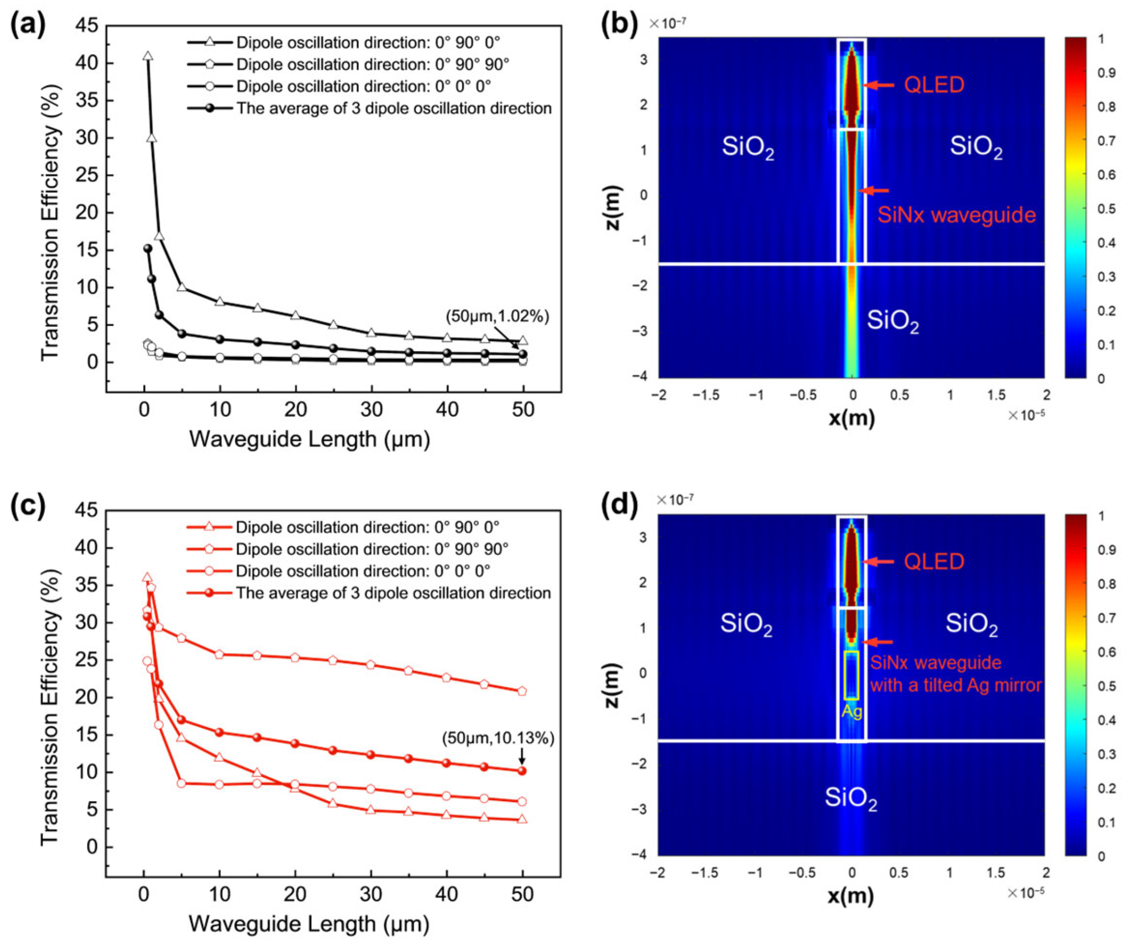
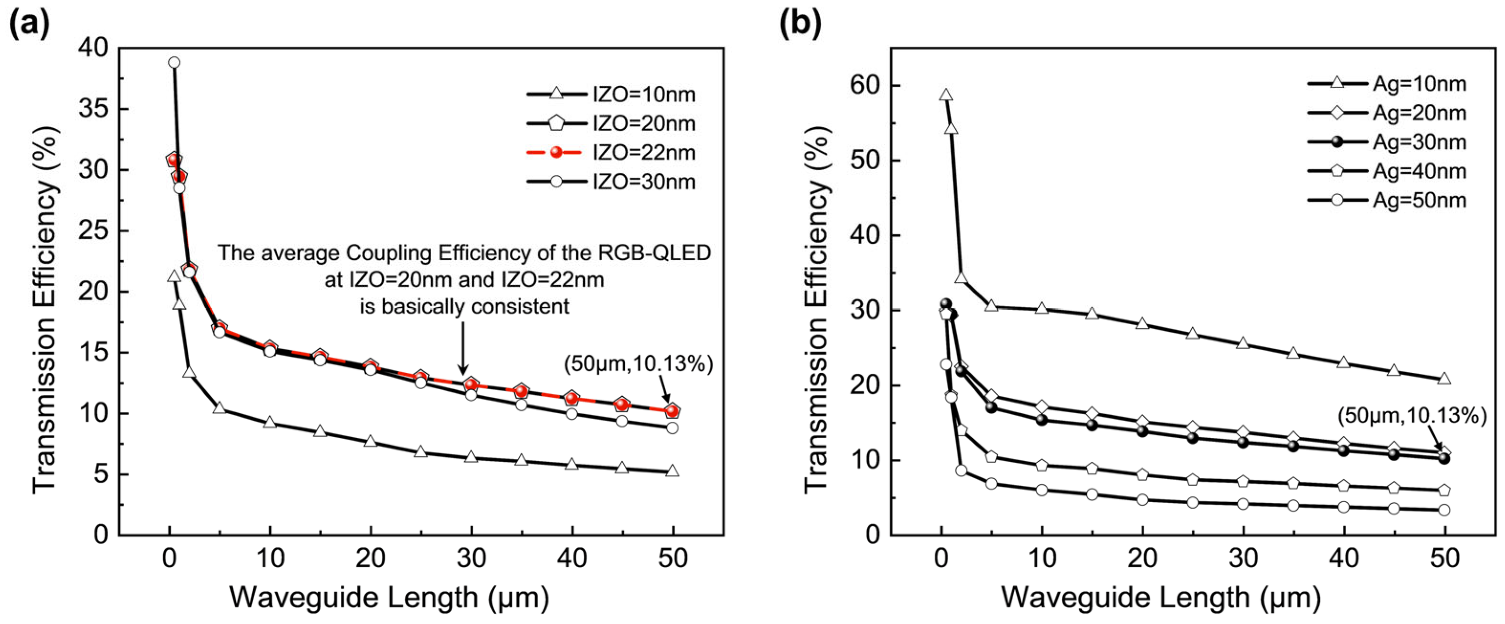
3.4. Output Efficiency of RGB-QLED Coupled with SiNx Waveguide

The constructed SiNx waveguide has dimensions of 120 μm in length, 60 μm in width, and 300 nm in height, and operates as a multimode waveguide. In the absence of a tilted reflective mirror, the output efficiency of the RGB-QLED coupled with SiNx waveguide is notably low. Figure 5a demonstrates the transmission efficiency for red light in the SiNx waveguide at an IZO thickness of 22 nm and an Ag electrode thickness of 30 nm. The output efficiency at the end of the waveguide, positioned at 50 μm, is only 1.02%. This low efficiency is due to the significant loss through the waveguide, where a considerable portion of the light either exits through the Si substrate or attenuates during propagation. Specifically, the waveguide loss at 50 μm reaches 3979 dB/cm. Figure 5b also provides energy distribution in a cross-sectional view without the tilted Ag mirror.
To improve the output efficiency, a tilted reflective Ag mirror is introduced into the SiNx waveguide. The introduced 45°-tilted Ag reflector has dimensions of 1 μm in length, 600 nm in width, and 100 nm in thickness. The impact of the tilted Ag mirror on the transmission efficiency is further illustrated in Figure 5c. Although the transmission efficiency still decreases with the transmission distance, the output efficiency rises to 10.31% at 50 μm, which is a tenfold increment compared to the sample without the tilted mirror. Finally, Figure 5d shows the cross-sectional electric field along the Y-axis with the tilted Ag mirror. The electric field is more focused, with less dispersion and a higher intensity along the waveguide. The tilted reflective mirror ensures that the light follows a more controlled path, reducing losses and significantly improving overall light transmission efficiency.
Taking the red-emitting RGB-QLED coupled with the SiNx waveguide as an example, the influence of microcavity modulation on the output efficiency is further investigated. Figure 6a illustrates the impact of IZO thickness on the output efficiency. When the IZO thickness is increased from 10 nm to 22 nm and the Ag electrode thickness is 30 nm, the output efficiency at 50 μm rises from 5.12% to 10.12%. However, when the IZO thickness exceeds 30 nm, the output efficiency decreases to 8.76%. This suggests that the optimal IZO thickness for efficient 620 nm red emission is between 20 nm and 22 nm. The peak output efficiency at this range is likely a result of the improved confinement of the emission angle and an enhanced microcavity effect. The red light emitted from the RGB-QLED is mostly confined from 25° to 35°, as shown in Figure 4d. With the tilted Ag mirror positioned at 45°, most of the light does not exceed the critical angle for TIR when passing through the SiNx, which maximizes light coupling into the waveguide. The effect of Ag anode thickness on output efficiency is shown in Figure 6b. With increasing Ag anode thickness and a fixed IZO thickness of 22 nm, the output efficiency at 50 μm gradually decreases, falling from 20.67% when the Ag anode is 10 nm to 3.26% when the Ag anode is 50 nm, marking a reduction of 15.78%. As the Ag anode thickness increases, its reflectivity increases [39], enhancing the microcavity interference effect and reducing the light coupled into the SiNx waveguide. This indicates that there is an inherent contradiction between high color purity and high output efficiency that needs to be balanced. The modulation of light by the tilted Ag mirror considerably influences the output efficiency. Therefore, it is essential to carefully select parameters such as IZO and anode Ag thickness to enhance both output efficiency and optical properties.

4. Conclusions

This work established two models with different original emission spectra of full-color QLEDs coupled with a SiNx waveguide using a broad-spectrum W-QLED and a comparatively narrow-spectrum mixed RGB-QLED, focusing on the effects of microcavity modulation on wavelength tuning, FWHM bandwidth narrowing, emission angle distribution, and output efficiency improvement of QLEDs coupled with SiNx waveguides. The thickness of the IZO layer changes from 20 nm to 140 nm, resulting in a shift of the emission peak across the visible spectrum from 400 nm to 750 nm. This modulation transforms both emissions from broadband white-light into narrowband single-wavelength outputs. Changes in the Ag anode thickness, which mainly change reflectivity and absorption, are shown to impact the FWHM, thereby affecting the coverage of the color gamut. Both W-QLED and RGB-QLED exhibit narrowing FWHMs as Ag anode thickness increases, but the extent of this narrowing differs. The FWHMs of RGB-QLED are 20.72 nm, 14.39 nm and 15.4 nm for red, green, and blue light, respectively. Furthermore, the color gamut of RGB-QLED is significantly enhanced, reaching 110.76% of NTSC 1953, representing a 20.95% improvement over W-QLED. These results highlight how modulating the microcavity by varying the reflectivity and microcavity length could effectively alter the emission properties of QLEDs. Comparative results further reveal the superior ability of RGB-QLED to achieve higher color purity compared to W-QLED. Additionally, the angular distribution of emission intensity reveals that there is also a correlation between IZO thickness and color shift, with a minimal color shift and angular distribution at the vertical direction from the emitting surface for green light. Moreover, the coupling between the RGB-QLED and SiNx waveguide are further explored by introducing a tilted Ag mirror to enhance output efficiency at the output end of the waveguide. The introduction of the tilted Ag mirror significantly increased the output efficiency, with the optimal coupling efficiency reaching 10.13%, a tenfold increment compared to the counterpart without the tilted Ag mirror. To clarify the emission properties of the RGB-QLED coupled with the SiNx waveguide, two comparative tables are provided. Table 1 summarizes the emission properties and output efficiency of waveguide-coupled QLEDs from this work and other related structures. Considering the distinct loss mechanisms between waveguide-coupled and uncoupled LEDs, it is inappropriate to directly compare their output efficiencies. Therefore, Table 2 presents a comparison of the emission properties, primarily FWHM and the NTSC 1953 color gamut, of the latest full-color LEDs based on different display technologies. Through investigation of microcavity modulation, this strategy highlights the potential of QLEDs coupled with SiNx waveguides in modern display technologies, offering an efficient and compact approach to enhance nanoscale full-color display technologies.
Table 1. Comparison of emission properties and output efficiency of waveguide-coupled LEDs with different structures.
TechnologyFWHM (nm)Output Efficiency (%)Reference
RGB-QLED (this work)14.3910.13 (SiNx)/
W-QLED (this work)21.11.02 (SiNx)/
QLED350.08 (SiNx)[24]
InGaAsP LED250.01–1 (InP)[46]
Black phosphorus LED4230.084 (Si)[47]
Table 2. Comparison of emission properties of latest full-color LEDs without waveguide coupling.
TechnologyFWHM (nm)NTSC 1953 Coverage (%)Reference
RGB-QLED (this work)14.39110.76/
W-QLED (this work)21.191.19/
OLED20125.6[48]
Perovskite LED15129[49]
Perovskite QLED16132[50]
Phosphorus LED6196[51]
GaN mini-LED~25113.63[52]
However, it is important to note that the conclusions of this work are derived from optical simulations decoupled from electrical processes. While this approach isolates the microcavity modulation effect, there are several factors that could influence experimental performance, including potential differences between PL and electroluminescence (EL) spectra due to carrier injection dynamics, and power-dependent spectral shifts arising from exciton saturation or thermal effects under varying operating power. Meanwhile, different EMLs with varied spectral properties may lead to different interactions with the microcavity. The performance of the microcavity modulation could be changed depending on the specific emission characteristics of the material, including the emission spectrum, refractive index, etc. While the simulations provide valuable insights into the influence of the microcavity modulation on optical properties, translating these results to experiments requires further consideration of the aforementioned factors.

Supplementary Materials

The following supporting information can be downloaded at: https://www.mdpi.com/article/10.3390/photonics12050427/s1, Supplementary S1: The detailed derivation of Equation (5); Table S1: Comparison between Δλ based on Equations (5) and (6) and simulated FWHMs for W-QLED and RGB-QLED. References [14,53,54] are cited in the supplementary materials.

Author Contributions

Conceptualization, D.W., W.W. and Y.Z.; methodology, G.M. and K.W.; software, W.W., F.Z., Y.Y. and J.T.; validation, Y.Z., J.Z. and H.Z.; formal analysis, F.Z.; investigation, G.M. and Q.J.; resources, D.W., B.H. and K.W.; data curation, W.W. and Y.Z.; writing—original draft preparation, W.W. and Y.Z.; writing—review and editing, D.W. and Y.Z.; visualization, W.W. and Y.Z.; supervision, D.W.; project administration, D.W. and K.W.; funding acquisition, B.H. All authors have read and agreed to the published version of the manuscript.

Funding

This work was supported by the National Key Research and Development Program of China (No. 2022YFB3606504); National Natural Science Foundation of China (No. 62475171); Guangdong Basic and Applied Basic Research Foundation (No. 2025A1515011655, No. 2019A1515111093); Shenzhen Stable Support Research Foundation (No. 20220717215521001); Natural Science Foundation of Top Talent of Shenzhen Technology University (SZTU) (No. GDRC202110); Shenzhen Key Laboratory of Applied Technologies of Super-Diamond and Functional Crystals (ZDSYS20230626091303007); Shenzhen Key Laboratory for Advanced Quantum Dot Displays and Lighting (No. ZDSYS201707281632549).

Institutional Review Board Statement

Not applicable.

Informed Consent Statement

Not applicable.

Data Availability Statement

Data are contained within the article.

Conflicts of Interest

The authors declare no conflicts of interest.

Abbreviations

The following abbreviations are used in this manuscript:
QLEDsQuantum dot light-emitting diodes
FWHMFull-width at half-maximum
TIRTotal internal reflection
SiNSilicon nitride
W-QLEDwhite light QLED
RGB-QLEDmixed RGB QDs
EMLEmitting layer
IZOIndium zinc oxide
HILHole injection layer
HTLHole transport layer
ETLElectron transport layer
QDsQuantum dots
CPSChance, Prock, and Sibley theory
FDTDFinite difference time domain
CIEThe International Commission on Illumination
PLPhotoluminescence
HSLHue, saturation, and luminance
NTSC 1953National Television System Committee 1953
sRGBStandard Red Green Blue

Appendix A. Refractive Index of All Materials Used

The complex refractive indices (n: refractive index, k: extinction coefficient) of all materials used in simulations are provided in Figure A1.
Figure A1. The refractive index spectra of materials in the simulation are presented. Reproduced with permission from [55]. Copyright 2015 IEEE. Reprinted with permission from [56]. Copyright 2018 American Chemical Society.
Photonics 12 00427 g0a1

References

  1. Zhang, Z.C.; You, Z.; Chu, D.P. Fundamentals of phase-only liquid crystal on silicon (LCOS) devices. Light-Sci. Appl. 2014, 3, e213. [Google Scholar] [CrossRef]
  2. Yin, K.; Hsiang, E.-L.; Zou, J.; Li, Y.; Yang, Z.; Yang, Q.; Lai, P.-C.; Lin, C.-L.; Wu, S.-T. Advanced liquid crystal devices for augmented reality and virtual reality displays: Principles and applications. Light-Sci. Appl. 2022, 11, 161. [Google Scholar] [CrossRef] [PubMed]
  3. Li, C.; Feng, M.; Liu, J.; Liu, W.; Sun, X.; Liu, J.; Sun, Z.; Zhu, G.; Zhang, S.; Sun, Q.; et al. GaN-Based Resonant-Cavity Light-Emitting Diode Towards a Vertical-Cavity Surface-Emitting Laser. IEEE J. Sel. Top. Quantum Electron. 2025, 31, 1–6. [Google Scholar] [CrossRef]
  4. Huang, J.; Tang, M.; Zhou, B.; Liu, Z.; Yi, X.; Wang, J.; Li, J.; Pan, A.; Wang, L. GaN-based resonant cavity micro-LEDs for AR application. Appl. Phys. Lett. 2022, 121, 201104. [Google Scholar] [CrossRef]
  5. Liu, Z.; Ren, K.; Dai, G.; Zhang, J. A Review on Micro-LED Display Integrating Metasurface Structures. Micromachines 2023, 14, 1354. [Google Scholar] [CrossRef]
  6. Xuan, T.; Shi, S.; Wang, L.; Kuo, H.-C.; Xie, R.-J. Inkjet-Printed Quantum Dot Color Conversion Films for High-Resolution and Full-Color Micro Light-Emitting Diode Displays. J. Phys. Chem. Lett. 2020, 11, 5184–5191. [Google Scholar] [CrossRef]
  7. Lee, T.; Kim, B.J.; Lee, H.; Hahm, D.; Bae, W.K.; Lim, J.; Kwak, J. Bright and Stable Quantum Dot Light-Emitting Diodes. Adv. Mater. 2022, 34, 2106276. [Google Scholar] [CrossRef]
  8. Yuan, T.; Yuan, F.L.; Sui, L.Z.; Zhang, Y.; Li, Y.C.; Li, X.H.; Tan, Z.A.; Fan, L.Z. Carbon Quantum Dots with Near-Unity Quantum Yield Bandgap Emission for Electroluminescent Light-Emitting Diodes. Angew. Chem.-Int. Ed. 2023, 62, e202218568. [Google Scholar] [CrossRef]
  9. Kim, J.; Roh, J.; Park, M.; Lee, C. Recent Advances and Challenges of Colloidal Quantum Dot Light-Emitting Diodes for Display Applications. Adv. Mater. 2024, 36, 2212220. [Google Scholar] [CrossRef]
  10. Jang, C.; Bang, K.; Chae, M.; Lee, B.; Lanman, D. Waveguide holography for 3D augmented reality glasses. Nat. Commun. 2024, 15, 66. [Google Scholar] [CrossRef]
  11. Gopakumar, M.; Lee, G.-Y.; Choi, S.; Chao, B.; Peng, Y.; Kim, J.; Wetzstein, G. Full-colour 3D holographic augmented-reality displays with metasurface waveguides. Nature 2024, 629, 791–797. [Google Scholar] [CrossRef] [PubMed]
  12. Yoo, C.; Bang, K.; Jang, C.; Kim, D.; Lee, C.K.; Sung, G.; Lee, H.S.; Lee, B. Dual-focal waveguide see-through near-eye display with polarization-dependent lenses. Opt. Lett. 2019, 44, 1920–1923. [Google Scholar] [CrossRef] [PubMed]
  13. Elsinger, L.; Tanghe, I.; Acker, F.V.; Zawacka, N.K.; Petit, R.; Neyts, K.; Detavernier, C.; Geiregat, P.; Hens, Z.; Thourhout, D.V. A Waveguide-Coupled Colloidal Quantum Dot LED on a Silicon Nitride Platform. In Proceedings of the 2020 Conference on Lasers and Electro-Optics (CLEO), San Jose, CA, USA, 10–15 May 2020; pp. 1–2. [Google Scholar]
  14. Yokoyama, H. Physics and Device Applications of Optical Microcavities. Science 1992, 256, 66–70. [Google Scholar] [CrossRef] [PubMed]
  15. Rozenman, G.G.; Peisakhov, A.; Zadok, N. Dispersion of organic exciton polaritons—A novel undergraduate experiment. Eur. J. Phys. 2022, 43, 035301. [Google Scholar] [CrossRef]
  16. Gomez-Dominguez, M.; Kumar, E.J.; Koch, K.A.; Srimath Kandada, A.R.; Correa-Baena, J.-P. Materials and Cavity Design Principles for Exciton-Polariton Condensates. ACS Nano 2025, 19, 10579–10588. [Google Scholar] [CrossRef]
  17. Mei, G.; Wang, W.; Wu, D.; Surman, P.A.; Wang, K.; Choy, W.C.H.; Yang, X.; Xu, W.; Sun, X.W. Full-Color Quantum Dot Light-Emitting Diodes Based on Microcavities. IEEE Photonics J. 2022, 14, 8219709. [Google Scholar] [CrossRef]
  18. Zhao, H.A.; Arneson, C.E.; Fan, D.J.; Forrest, S.R. Stable blue phosphorescent organic LEDs that use polariton-enhanced Purcell effects. Nature 2024, 626, 300–305. [Google Scholar] [CrossRef]
  19. Huang, S.-H.; Su, H.-P.; Chen, C.; Lin, Y.; Yang, Z.; Shi, Y.; Song, Q.; Wu, P.C. Microcavity-assisted multi-resonant metasurfaces enabling versatile wavefront engineering. Nat. Commun. 2024, 15, 9658. [Google Scholar] [CrossRef]
  20. Mei, G.; Xiao, X.; Ahmad, S.; Lin, H.; Tan, Y.; Wang, K.; Sun, X.W.; Choy, W.C.H. Microcavity Design Upping Light Extraction Efficiency over 50% in High-Index Perovskite Light-Emitting Diodes. Adv. Opt. Mater. 2023, 11, 2300912. [Google Scholar] [CrossRef]
  21. Yu, P.C.; Topolancik, J.; Chakravarty, S.; Bhattacharya, P. Mode-coupling characteristics and efficiency of quantum-dot electrically injected photonic crystal waveguide-coupled light-emitting diodes. IEEE J. Quantum Electron. 2005, 41, 455–460. [Google Scholar] [CrossRef]
  22. Xu, X.J.; Maruizumi, T.; Shiraki, Y. Waveguide-integrated microdisk light-emitting diode and photodetector based on Ge quantum dots. Opt. Express 2014, 22, 3902–3910. [Google Scholar] [CrossRef] [PubMed]
  23. Ren, J.; Meijerink, A.; Zhou, X.; Wu, J.; Zhang, G.; Wang, Y. In Situ Embedding Synthesis of CsPbBr3@Ce-MOF@SiO2 Nanocomposites for High Efficiency Light-Emitting Diodes: Suppressing Reabsorption Losses through the Waveguiding Effect. ACS Appl. Mater. Interfaces 2022, 14, 3176–3188. [Google Scholar] [CrossRef] [PubMed]
  24. Elsinger, L.; Petit, R.; Van Acker, F.; Zawacka, N.K.; Tanghe, I.; Neyts, K.; Detavernier, C.; Geiregat, P.; Hens, Z.; Van Thourhout, D. Waveguide-Coupled Colloidal Quantum Dot Light Emitting Diodes and Detectors on a Silicon Nitride Platform. Laser Photonics Rev. 2021, 15, 2000230. [Google Scholar] [CrossRef]
  25. Steindorfer, M.A.; Lamprecht, B.; Schmidt, V.; Abel, T.; Mayr, T.; Krenn, J.R. Light coupling for integrated optical waveguide-based sensors. In Optical Sensing and Detection; SPIE: Bellingham, WA, USA, 2010; p. 77261S. [Google Scholar]
  26. Bulović, V.; Khalfin, V.B.; Gu, G.; Burrows, P.E.; Garbuzov, D.Z.; Forrest, S.R. Weak microcavity effects in organic light-emitting devices. Phys. Rev. B 1998, 58, 3730–3740. [Google Scholar] [CrossRef]
  27. Ye, T.; Tian, D.; Wu, D.; Sun, X.W.; Wang, K. Submicron quantum dot light-emitting diodes enabled by pixelated topological meta-mirror. Nanophotonics 2025, 14, 241–251. [Google Scholar] [CrossRef]
  28. He, P.; Lan, L.; Deng, C.; Wang, J.; Peng, J.; Cao, Y. Highly efficient and stable hybrid quantum-dot light-emitting field-effect transistors. Mater. Horiz. 2020, 7, 2439–2449. [Google Scholar] [CrossRef]
  29. Xiang, C.Y.; Koo, W.; So, F.; Sasabe, H.; Kido, J. A systematic study on efficiency enhancements in phosphorescent green, red and blue microcavity organic light emitting devices. Light-Sci. Appl. 2013, 2, e74. [Google Scholar] [CrossRef]
  30. Han, S.; Huang, C.; Lu, Z.-H. Color tunable metal-cavity organic light-emitting diodes with fullerene layer. J. Appl. Phys. 2005, 97, 093102. [Google Scholar] [CrossRef]
  31. Dodabalapur, A.; Rothberg, L.J.; Jordan, R.H.; Miller, T.M.; Slusher, R.E.; Phillips, J.M. Physics and applications of organic microcavity light emitting diodes. J. Appl. Phys. 1996, 80, 6954–6964. [Google Scholar] [CrossRef]
  32. Clarke, D. Appendix A: The Fresnel Laws. In Stellar Polarimetry; Wiley: New York, NY, USA, 2009; pp. 365–385. [Google Scholar]
  33. Tsai, D.-C.; Chang, Z.-C.; Kuo, B.-H.; Wang, Y.-H.; Chen, E.-C.; Shieu, F.-S. Thickness dependence of the structural, electrical, and optical properties of amorphous indium zinc oxide thin films. J. Alloys Compd. 2018, 743, 603–609. [Google Scholar] [CrossRef]
  34. Man, J.; He, S.; Shi, C.; Yang, H.; Wang, D.; Lu, Z. Optical design of connecting electrodes for tandem organic light-emitting diodes. Opt. Lett. 2020, 45, 3561–3564. [Google Scholar] [CrossRef]
  35. Schubert, E.F.; Hunt, N.E.J.; Micovic, M.; Malik, R.J.; Sivco, D.L.; Cho, A.Y.; Zydzik, G.J. Highly Efficient Light-Emitting Diodes with Microcavities. Science 1994, 265, 943–945. [Google Scholar] [CrossRef] [PubMed]
  36. Deppe, D.G.; Lei, C.; Lin, C.C.; Huffaker, D.L. Spontaneous Emission from Planar Microstructures. J. Mod. Opt. 1994, 41, 325–344. [Google Scholar] [CrossRef]
  37. Cao, J.; Liu, X.; Khan, M.A.; Zhu, W.; Jiang, X.; Zhang, Z.; Xu, S. RGB tricolor produced by white-based top-emitting organic light-emitting diodes with microcavity structure. Curr. Appl. Phys. 2007, 7, 300–304. [Google Scholar] [CrossRef]
  38. Alharbi, R. Reflectivity and Elastic Modulus of Nano-Aluminum Films on Silicon Crystal Substrates. Master’s Thesis, University of Waterloo, Waterloo, ON, Canada, 2014. [Google Scholar]
  39. Sun, X.; Hong, R.; Hou, H.; Fan, Z.; Shao, J. Thickness dependence of structure and optical properties of silver films deposited by magnetron sputtering. Thin Solid Film. 2007, 515, 6962–6966. [Google Scholar] [CrossRef]
  40. Chance, R.R.; Prock, A.; Silbey, R. Molecular Fluorescence and Energy Transfer Near Interfaces. In Advances in Chemical Physics; Wiley: New York, NY, USA, 1978; pp. 1–65. [Google Scholar]
  41. Marcuse, D. Reflection loss of laser mode from tilted end mirror. J. Light. Technol. 1989, 7, 336–339. [Google Scholar] [CrossRef]
  42. Cho, I.-K.; Lee, W.-J.; Rho, B.-S.; Jeong, M.-Y. Polymer waveguide with integrated reflector mirrors for an inter-chip link system. Opt. Commun. 2008, 281, 4906–4909. [Google Scholar] [CrossRef]
  43. Tang, Y.Z.; Wang, W.H.; Li, T.; Wang, Y.L. Integrated waveguide turning mirror in silicon-on-insulator. IEEE Photonics Technol. Lett. 2002, 14, 68–70. [Google Scholar] [CrossRef]
  44. Tan, G.; Lee, J.-H.; Lin, S.-C.; Zhu, R.; Choi, S.-H.; Wu, S.-T. Analysis and optimization on the angular color shift of RGB OLED displays. Opt. Express 2017, 25, 33629–33642. [Google Scholar] [CrossRef]
  45. Buchholz, D.B.; Liu, J.; Marks, T.J.; Zhang, M.; Chang, R.P.H. Control and Characterization of the Structural, Electrical, and Optical Properties of Amorphous Zinc−Indium−Tin Oxide Thin Films. ACS Appl. Mater. Interfaces 2009, 1, 2147–2153. [Google Scholar] [CrossRef]
  46. Dolores-Calzadilla, V.; Romeira, B.; Pagliano, F.; Birindelli, S.; Higuera-Rodriguez, A.; van Veldhoven, P.J.; Smit, M.K.; Fiore, A.; Heiss, D. Waveguide-coupled nanopillar metal-cavity light-emitting diodes on silicon. Nat. Commun. 2017, 8, 14323. [Google Scholar] [CrossRef] [PubMed]
  47. Chang, T.-Y.; Chen, Y.; Luo, D.-I.; Li, J.-X.; Chen, P.-L.; Lee, S.; Fang, Z.; Li, W.-Q.; Zhang, Y.-Y.; Li, M.; et al. Black Phosphorus Mid-Infrared Light-Emitting Diodes Integrated with Silicon Photonic Waveguides. Nano Lett. 2020, 20, 6824–6830. [Google Scholar] [CrossRef] [PubMed]
  48. Lin, Y.; Zhu, Y.; Zhao, B.; Gu, J.; Xu, Y.; Lan, W.; Chen, G.; Shi, W.; Kido, J.; Wei, B. High color gamut top-emitting organic light-emitting diode based on metal/transparent conductive oxide composite electrode. Mater. Today Chem. 2025, 45, 102612. [Google Scholar] [CrossRef]
  49. Liu, W.; Qi, Z.; Liu, T.; Zhang, Y. Fluoride Ion Passivation of CsPbBr3 Nanocrystals at Room Temperature for Highly Efficient and Stable White Light-Emitting Diodes. ACS Appl. Mater. Interfaces 2025, 17, 17143–17152. [Google Scholar] [CrossRef] [PubMed]
  50. Cai, J.; Ren, X.; Zhang, X.; Lai, W.; Chen, Y.; Chen, X.; Li, G.; Zha, N.; Ye, Y.; Xu, S.; et al. In Situ Ring Opening Polymerization of High-Performance Full-Color CsPbX3@PDMS (X = Cl, Br, I) Nanospheres Toward Wide-Color-Gamut Displays. Small 2025, 21, 2410180. [Google Scholar] [CrossRef]
  51. Yang, X.; Tang, Z.; Song, F.; Leng, Z. Achieving successful reduction of Eu3+ to Eu2+ in NaYSiO4 lattice towards lighting & display applications by a two-pronged approach. J. Alloys Compd. 2025, 1011, 178372. [Google Scholar] [CrossRef]
  52. Gao, F.; Zhang, N.; Bai, Z.; Lu, Y.; Chen, Z.; Guo, W. Deep Learning for Chromatic Optimization in Dual-Color Mini-LEDs for Aircraft Displays. Laser Photonics Rev. 2025, 2402087. [Google Scholar] [CrossRef]
  53. Liu, H.; Lin, T.; Wan, L.; Xu, G.; Kuo, H.-C.; Feng, Z.C. Modelling of microcavity effect in InGaN/GaN heterostructures for interfacial study. Mater. Res. Express 2018, 5, 086201. [Google Scholar] [CrossRef]
  54. Noda, S.; Fujita, M.; Asano, T. Spontaneous-emission control by photonic crystals and nanocavities. Nat. Photonics 2007, 1, 449–458. [Google Scholar] [CrossRef]
  55. Morales-Masis, M.; Nicolas, S.M.D.; Holovsky, J.; Wolf, S.D.; Ballif, C. Low-Temperature High-Mobility Amorphous IZO for Silicon Heterojunction Solar Cells. IEEE J. Photovolt. 2015, 5, 1340–1347. [Google Scholar] [CrossRef]
  56. Salehi, A.; Chen, Y.; Fu, X.; Peng, C.; So, F. Manipulating Refractive Index in Organic Light-Emitting Diodes. ACS Appl. Mater. Interfaces 2018, 10, 9595–9601. [Google Scholar] [CrossRef] [PubMed]
Figure 1. The structure of a QLED coupled with SiNx waveguide is shown: (a) the overall schematic structure, (b) wide-angle structure, (c) multiple-beam interference, and (d) red, blue and green resonance waves from the EML due to the microcavity effect enabled by different IZO thickness.
Photonics 12 00427 g001
Figure 2. Wavelength tuning of (a) W-QLED, and (b) RGB-QLED is achieved through IZO thickness variation by microcavity effect, with the background showing the photoluminescence (PL) spectra for each.
Photonics 12 00427 g002
Figure 3. The emission spectra of W-QLED and RGB-QLED with varying Ag anode thicknesses (10 nm to 40 nm) of green light are shown in (a,b), a FWHM comparison in (c), spectra with varying IZO and anode Ag thicknesses in (d,e), and CIE 1931 color gamut comparisons in (f).
Photonics 12 00427 g003
Figure 4. The intensity angular distributions of W-QLEDs and RGB-QLEDs under optimized IZO thickness for different emission colors are shown in: (a,d) for red emission, (b,e) for blue emission, and (c,f) for green emission.
Photonics 12 00427 g004
Figure 5. The transmission efficiency in the SiNx waveguide and cross-sectional view of electric field for the red-emitting RGB-QLED coupled with the SiNx waveguide: (a,b) without a tilted reflective mirror, and (c,d) with the tilted Ag mirror in the waveguide.
Photonics 12 00427 g005
Figure 6. Taking red-emitting RGB-QLED coupled with the SiNx waveguide as an example, (a,b) illustrate the effect of IZO spacer thickness and Ag anode thickness on output efficiency.
Photonics 12 00427 g006
Disclaimer/Publisher’s Note: The statements, opinions and data contained in all publications are solely those of the individual author(s) and contributor(s) and not of MDPI and/or the editor(s). MDPI and/or the editor(s) disclaim responsibility for any injury to people or property resulting from any ideas, methods, instructions or products referred to in the content.

